HORN
Horn Wiring Diagram, with Power Equipment for Mazda B2500 SX 2001
 https://portal-diagnostov.com/license.html
Automotive Electricians Portal FZCO
Automotive Electricians Portal FZCO
https://portal-diagnostov.com/license.html
https://portal-diagnostov.com/license.html
Automotive Electricians Portal FZCO
Automotive Electricians Portal FZCO
List of elements for Horn Wiring Diagram, with Power Equipment for Mazda B2500 SX 2001:
- 15a
- 20a
- 7.5a
- Battery junction box (left rear of engine compt)
- Central junction box (behind left side of dash)
- Central security module (behind right upper side of dash)
- Clock spring
- Cruise control system
- Fuse 11
- Fuse 33
- Fuse 8
- G105 (rear of right front fender apron)
- G200 (left kick panel)
- G203 (right kick) panel)
- Horn (right front side of engine compartment)
- Horn switch
- Hot at all times
- Hot in run or start
- Nca
- Ohms
- Steering wheel
- T-409
- T-410
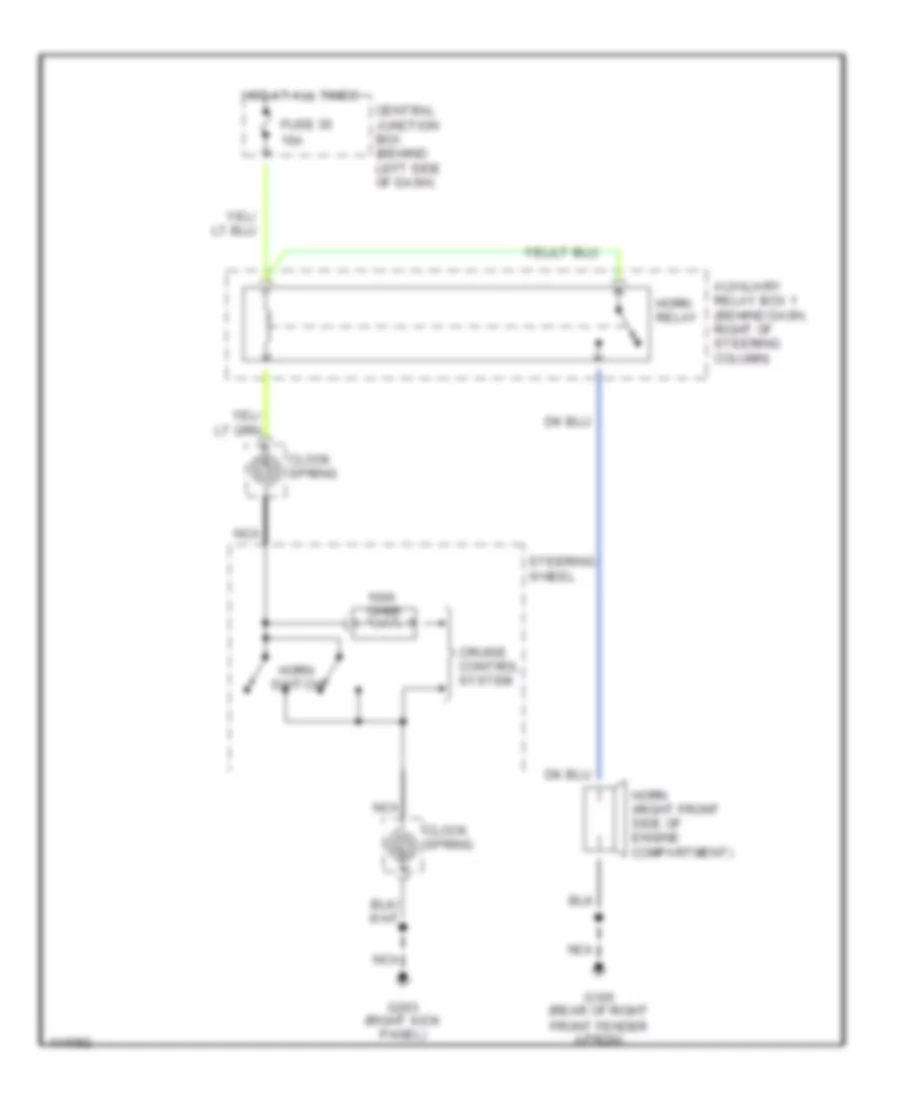
Horn Wiring Diagram, without Power Equipment for Mazda B2500 SX 2001
List of elements for Horn Wiring Diagram, without Power Equipment for Mazda B2500 SX 2001:
- 15a
- Auxiliary relay box 1 (behind dash, right of steering column)
- Central junction box (behind left side of dash)
- Clock spring
- Cruise control system
- Fuse 35
- G105 (rear of right front fender apron)
- G203 (right kick panel)
- Horn (right front side of engine compartment)
- Horn relay
- Horn switch
- Hot at all times
- Nca
- Ohms
- Steering wheel

 Čeština
 Dansk
Dansk Deutsch
 English
 English
 Español
 Suomi
Suomi Français
 Français
 עברית
עברית Hrvatski
 Magyar
 Italiano
 日本語
日本語 한국어
한국어 Nederlands
 Polski
 Português
 Português
 Română
 Русский
 Slovenčina
 Slovenščina
 Svenska
 Türkçe
 中文 (中国)