ANTI-LOCK BRAKES
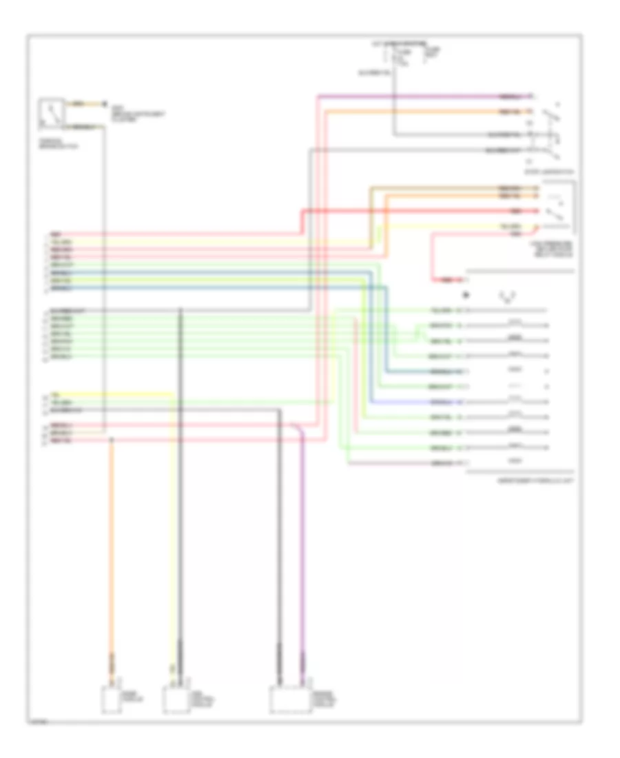
Anti-lock Brake Wiring Diagrams, with Acceleration Slip Regulation (1 of 2) for Mercedes-Benz S320 1999
 https://portal-diagnostov.com/license.html
Automotive Electricians Portal FZCO
Automotive Electricians Portal FZCO
https://portal-diagnostov.com/license.html
https://portal-diagnostov.com/license.html
Automotive Electricians Portal FZCO
Automotive Electricians Portal FZCO
List of elements for Anti-lock Brake Wiring Diagrams, with Acceleration Slip Regulation (1 of 2) for Mercedes-Benz S320 1999:
- (right footwell)
- Abs lateral acceleration sensor (s420/s500)
- Asr off switch
- Asr/ets/sps control module
- Computer data lines system
- Data link connector
- Engine controls, radio, headlights system (vehicle speed signal)
- G203
- G203 (right footwell)
- Hot at all times
- Interior lights system
- Left front axle vss speed sensor
- Left front brake pad wear sensor
- Left rear axle vss speed sensor
- Master brake cylinder switchover valve
- Nca
- Red
- Right front axle vss speed sensor
- Right front brake pad wear sensor
- Right rear axle vss speed sensor
- Right rear brake pad wear sensor
- Sps p-valve
- Terminal block (x4/10) (right rear of engine compt)
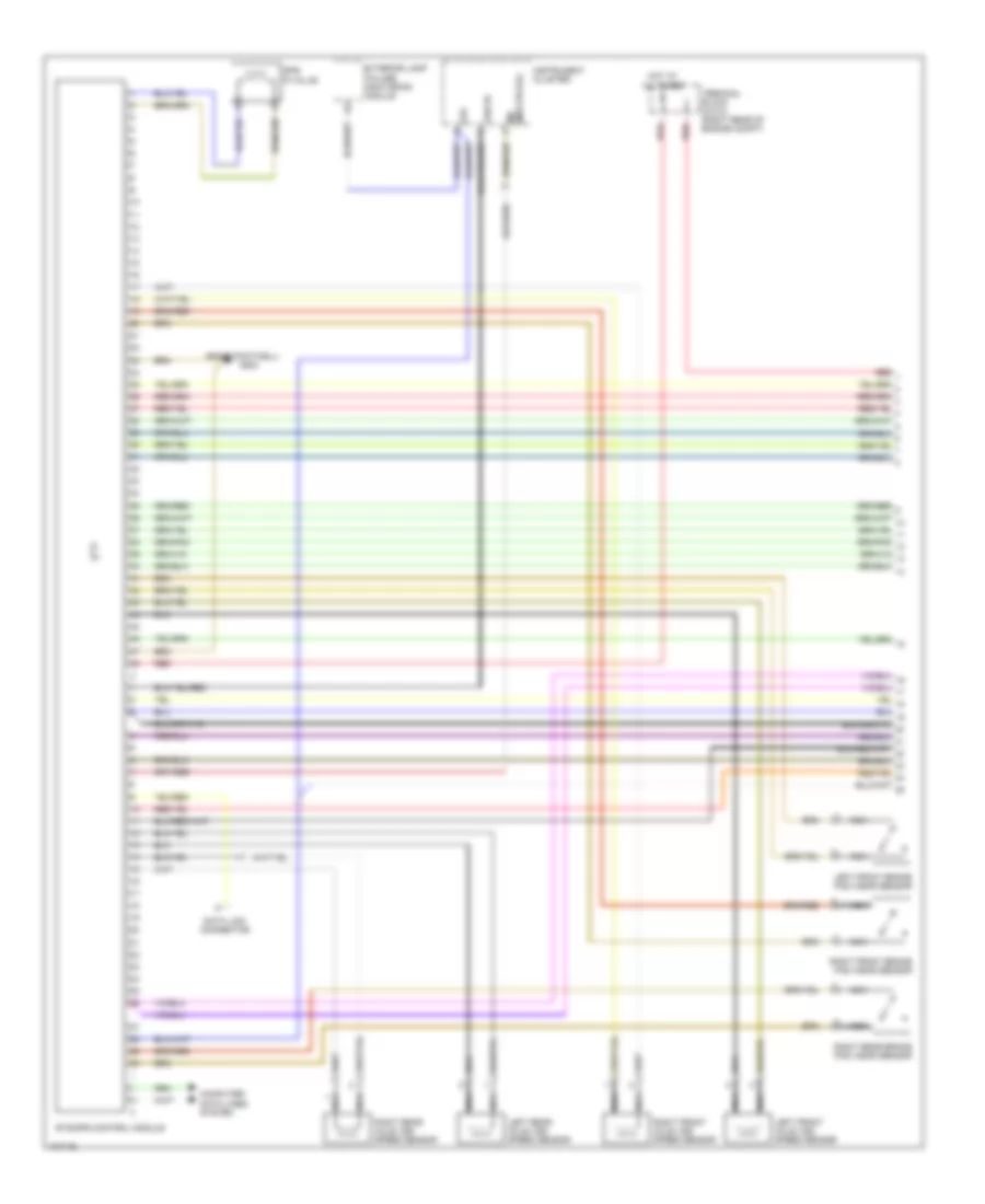
Anti-lock Brake Wiring Diagrams, with Acceleration Slip Regulation (2 of 2) for Mercedes-Benz S320 1999
List of elements for Anti-lock Brake Wiring Diagrams, with Acceleration Slip Regulation (2 of 2) for Mercedes-Benz S320 1999:
- Ads control module
- Asr/ets/esp hydraulic unit
- Base module
- Engine control module
- Fuse 7.5a
- Fuse box
- G202 (behind instrument cluster)
- High pressure/ return pump relay module
- Hot in run or start
- Parking brake switch
- Red
- Stop lamp switch
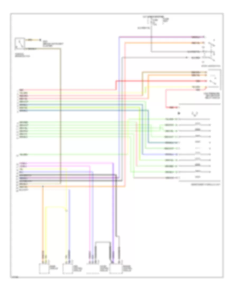
Anti-lock Brake Wiring Diagrams, with Traction Control (1 of 2) for Mercedes-Benz S320 1999
List of elements for Anti-lock Brake Wiring Diagrams, with Traction Control (1 of 2) for Mercedes-Benz S320 1999:
- (right footwell)
- 61e
- Computer data lines system
- Data link connector
- Ets/sps control module
- Exterior lamp failure monitoring module
- G203
- Hot at all times
- Instrument cluster
- Left front axle vss speed sensor
- Left front brake pad wear sensor
- Left rear axle vss speed sensor
- Mil (multiplex)
- Nca
- Red
- Right front axle vss speed sensor
- Right front brake pad wear sensor
- Right rear axle vss speed sensor
- Right rear brake pad wear sensor
- Sps p-valve
- Terminal block (x4/10) (right rear of engine compt)
- Vss rf
Anti-lock Brake Wiring Diagrams, with Traction Control (2 of 2) for Mercedes-Benz S320 1999
List of elements for Anti-lock Brake Wiring Diagrams, with Traction Control (2 of 2) for Mercedes-Benz S320 1999:
- Ads control module
- Asr/ets/esp hydraulic unit
- Base module
- Cc/isc control module
- Engine control module
- Fuse 7.5a
- Fuse box
- G202 (behind instrument cluster)
- High pressure/ return pump relay module
- Hot in run or start
- Parking brake switch
- Red
- Stop lamp switch
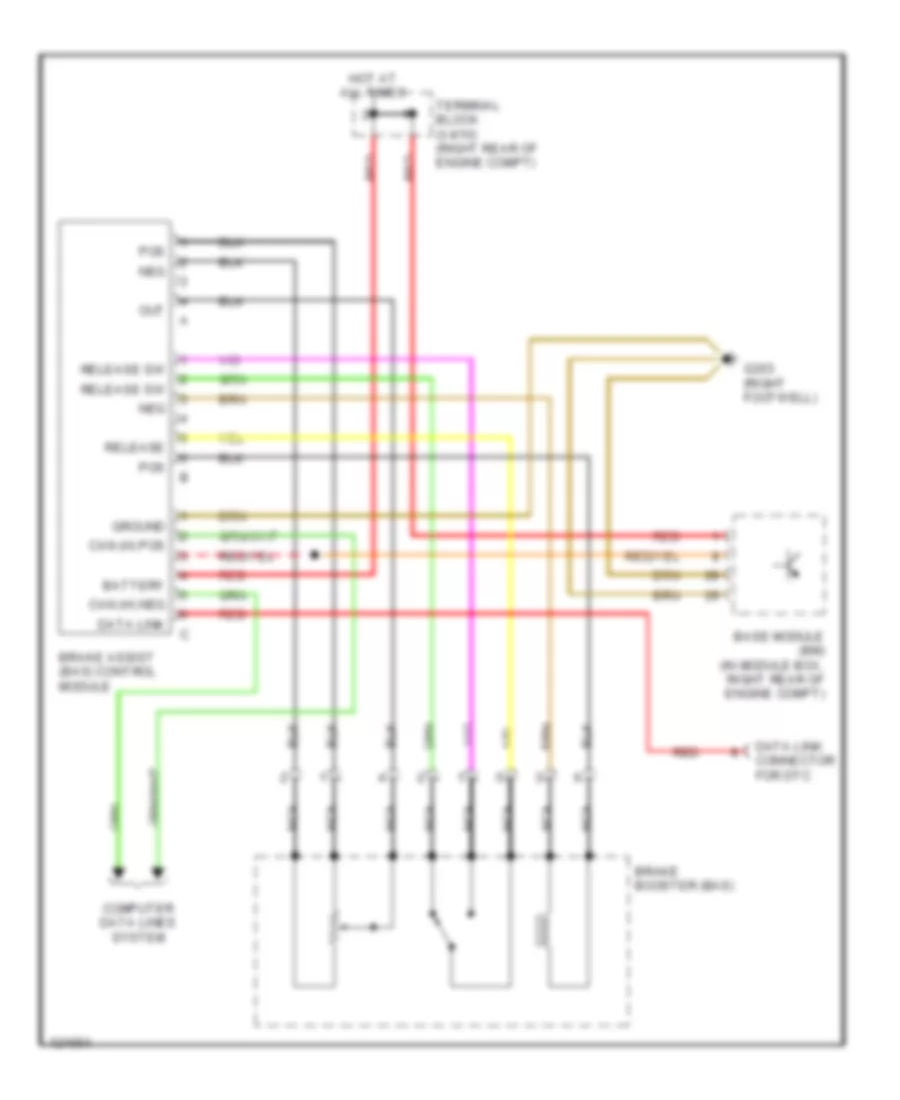
Brake Assist Wiring Diagram for Mercedes-Benz S320 1999
List of elements for Brake Assist Wiring Diagram for Mercedes-Benz S320 1999:
- Base module (bm) (in module box, right rear of engine compt)
- Battery
- Brake assist (bas) control module
- Brake booster (bas)
- Can (h) pos
- Computer data lines system
- Data link
- Data link connector for dtc
- G203 (right footwell)
- Ground
- Hot at all times
- Nca
- Out
- Pos
- Red
- Release
- Release sw
- Terminal block (x4/10) (right rear of engine compt)

 Čeština
 Dansk
Dansk Deutsch
 English
 English
 Español
 Suomi
Suomi Français
 Français
 עברית
עברית Hrvatski
 Magyar
 Italiano
 日本語
日本語 한국어
한국어 Nederlands
 Polski
 Português
 Português
 Română
 Русский
 Slovenčina
 Slovenščina
 Svenska
 Türkçe
 中文 (中国)