ENGINE PERFORMANCE
5.0L
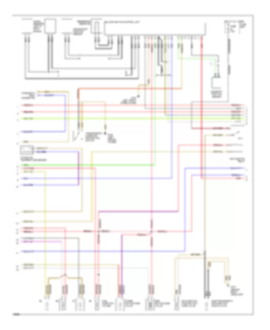
5.0L, Engine Performance Wiring Diagrams (1 of 3) for Mercedes-Benz 500SEL 1993
 https://portal-diagnostov.com/license.html
Automotive Electricians Portal FZCO
Automotive Electricians Portal FZCO
https://portal-diagnostov.com/license.html
https://portal-diagnostov.com/license.html
Automotive Electricians Portal FZCO
Automotive Electricians Portal FZCO
List of elements for 5.0L, Engine Performance Wiring Diagrams (1 of 3) for Mercedes-Benz 500SEL 1993:
- Air mass sensor/ hot wire
- Coolant temperature sensor
- Fuel injection valves
- Fuel pump package
- Fuel pumps relay
- Fuse 30a
- G203 (right side foot well)
- G203 (right side footwell)
- G303 (right rear seat)
- Heated sensor
- Hot at all times
- Instrument cluster system
- Left adjustable cam timing solenoid
- Lh control unit
- Nca
- Rear fuse box
- Red
- Right adjustable cam timing solenoid
- Starting/charging system (starter lock-out/backup lamp/selector lever position recognition switch)
- Upshift delay solenoid/ switch- over valve
5.0L, Engine Performance Wiring Diagrams (2 of 3) for Mercedes-Benz 500SEL 1993
List of elements for 5.0L, Engine Performance Wiring Diagrams (2 of 3) for Mercedes-Benz 500SEL 1993:
- Air injection pump switch- over valve
- Air injection relay
- Camshaft position sensor
- Connector
- Crankshaft position sensor
- Diagnostic
- Egr switchover valve
- Electromagnetic air injection pump clutch
- Ezl/akr ignition control unit
- Fuel injection valves
- Fuse 7.5a
- Fuse box
- G100 (left front wheelhouse)
- G102 (left spring tower)
- G107 (behind right headlamp)
- Hot at all times
- Intake air temperature sensor
- Knock sensors (left & right banks)
- Nca
- Purge switchover valve
- Red
- Reference resistor
- Test
- Transmission overload protection switch
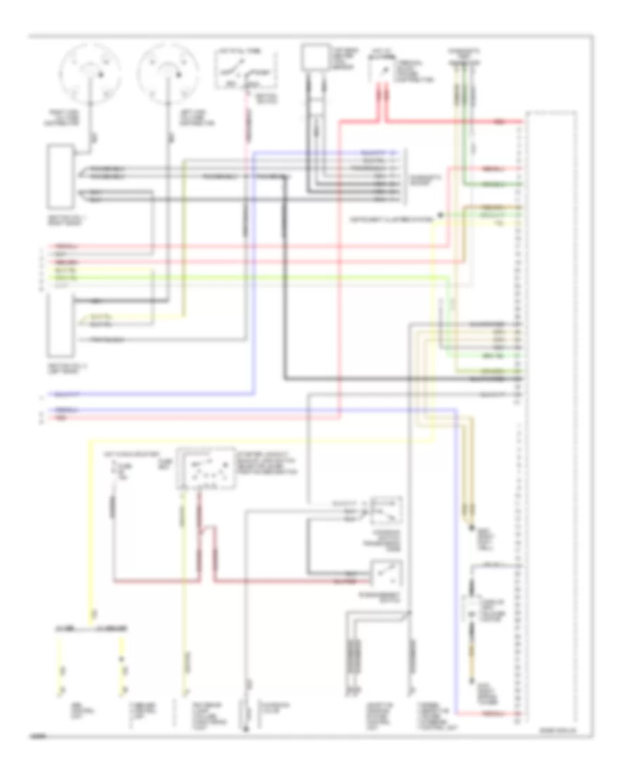
5.0L, Engine Performance Wiring Diagrams (3 of 3) for Mercedes-Benz 500SEL 1993
List of elements for 5.0L, Engine Performance Wiring Diagrams (3 of 3) for Mercedes-Benz 500SEL 1993:
- 'b' engagement switch
- Abs control unit
- Abs/asr control unit
- Acc
- Adaptive damping system control unit
- Base module
- Diagnostic socket
- Diagnostic test connector
- Exterior lamp failure monitoring unit
- Fuse 15a
- Fuse box
- G103 (right spring tower)
- G203 (right foot- well)
- Hot at all times
- Hot in run or start
- Ignition coil 1 (right bank)
- Ignition coil 2 (left bank)
- Ignition switch
- Instrument clusters system
- Kickdown switch/ transmission mode
- Kickdown valve
- Left high voltage distributor
- Module box blower motor
- Nca
- Off
- Red
- Right high voltage distributor
- Run
- Speed sensitive power steering control unit
- Start
- Starter lockout/ backup lamp switch selector lever position recognition
- Terminal block (power distribution)
- Top dead center (tdc) sensor
- W/ abs
- W/ abs/asr

 Čeština
 Dansk
Dansk Deutsch
 English
 English
 Español
 Suomi
Suomi Français
 Français
 עברית
עברית Hrvatski
 Magyar
 Italiano
 日本語
日本語 한국어
한국어 Nederlands
 Polski
 Português
 Português
 Română
 Русский
 Slovenčina
 Slovenščina
 Svenska
 Türkçe
 中文 (中国)