NAVIGATION
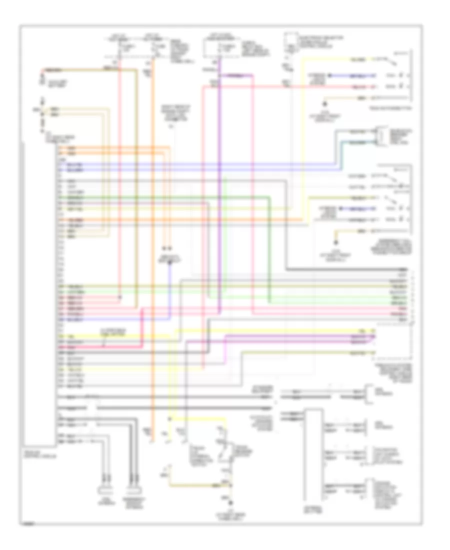
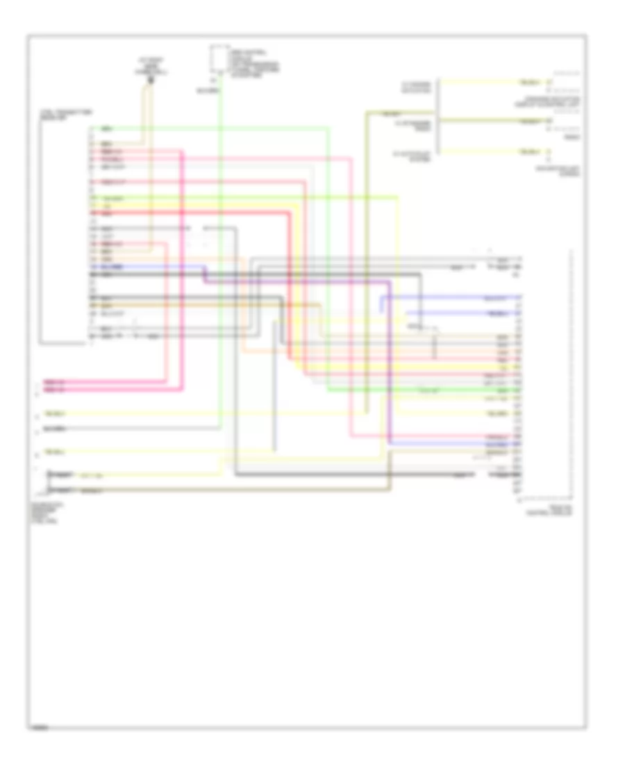
Parktronic Wiring Diagram, Convertible for Mercedes-Benz CLK320 2003
 https://portal-diagnostov.com/license.html
Automotive Electricians Portal FZCO
Automotive Electricians Portal FZCO
https://portal-diagnostov.com/license.html
https://portal-diagnostov.com/license.html
Automotive Electricians Portal FZCO
Automotive Electricians Portal FZCO
List of elements for Parktronic Wiring Diagram, Convertible for Mercedes-Benz CLK320 2003:
- (coupe) (right front door sill)
- 58l
- A lwr
- Cabriolet
- Coupe
- Data link connector (right rear of engine compt)
- Diag
- Esp/bas control module
- F data
- Front bumper pts sensor assembly (behind center of front bumper)
- Fuse & relay box (left rear of engine compt)
- Fuse 5a
- Hot in run or start
- Illum
- Illumination control module
- Interior lights system
- Left center sensor
- Left inner sensor
- Left outer sensor
- On/off
- Pts
- Pts on/off switch
- Pts warning indicator (center instrument panel air outlet)
- Pts warning indicator (left instrument panel air outlet)
- Pts warning indicator (rear dome lamp)
- R data
- Rear bumper pts sensor assembly (behind center of rear bumper)
- Rf erk
- Right center sensor
- Right inner sensor
- Right outer sensor
- Sensor 10r
- Sensor 1f
- Sensor 2f
- Sensor 3f
- Sensor 4f
- Sensor 5f
- Sensor 6f
- Sensor 7r
- Sensor 8r
- Sensor 9r
- Ultrasonic pts control module (under front passenger's foot well foot plate)
- Vss rf
- W19 w29/2 (cabriolet) (behind right end of dash)
- W29/2 (behind right end of dash)
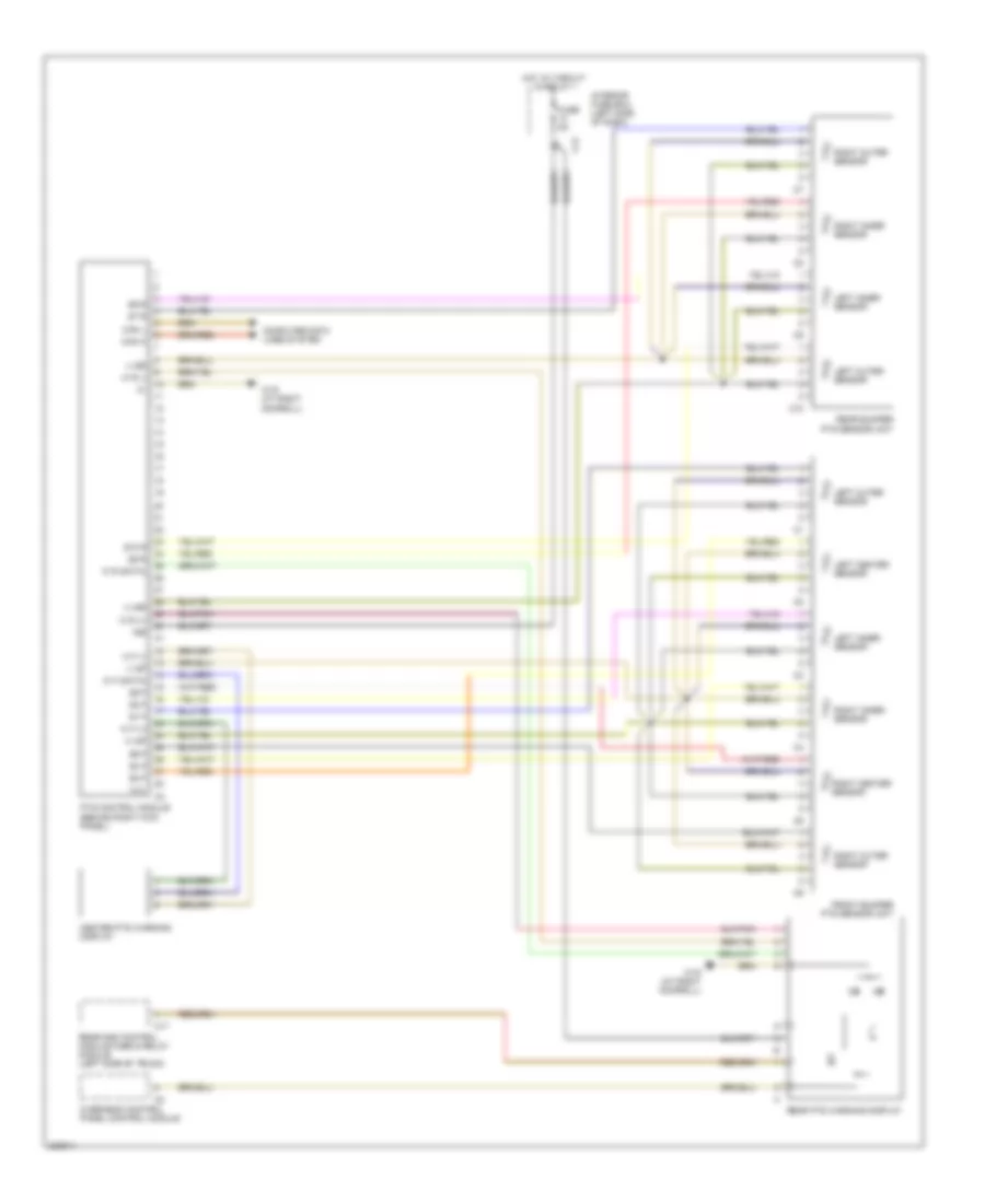
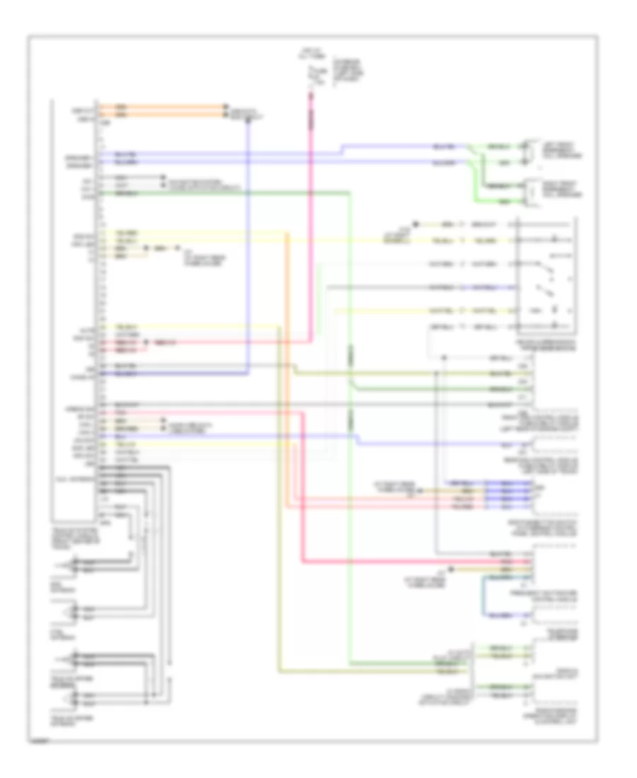
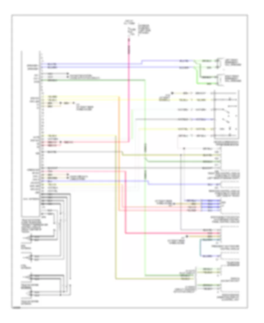
Parktronic Wiring Diagram, Except Convertible for Mercedes-Benz CLK320 2003
List of elements for Parktronic Wiring Diagram, Except Convertible for Mercedes-Benz CLK320 2003:
- (+) sf
- (+) sr
- (-) sf
- (-) sr
- 15r
- C10
- C12
- C17
- Can h
- Can l
- Center pts warning display
- Computer data lines system
- Front bumper pts sensor unit
- Fuse 5a
- Hot at circuit 15 relay 1
- Interior fuse box (left side of dash)
- Left center sensor
- Left inner sensor
- Left outer sensor
- N.c.
- Overhead control panel control module
- Pts control module (behind right kick panel)
- Rear bumper pts sensor unit
- Rear pts warning display
- Rear sam control module fuse & relay module (left side of trunk)
- Right center sensor
- Right inner sensor
- Right outer sensor
- S1 f
- S10 r
- S2 f
- S3 f
- S4 f
- S5 f
- S6 f
- S7 r
- S8 r
- S9 r
- W f (+)
- W f (-)
- W f (data)
- W r (+)
- W r (-)
- W r (data)
- W19 (at right doorsill)
Tele Aid Wiring Diagram, Convertible with D2B Data Bus (1 of 2) for Mercedes-Benz CLK320 2003
List of elements for Tele Aid Wiring Diagram, Convertible with D2B Data Bus (1 of 2) for Mercedes-Benz CLK320 2003:
- (right rear of engine compt) data link connector
- Antenna splitter
- Auto pilot/ command actuation system
- Auxiliary battery
- Comand actuation display & control unit (w/ comand actuation) system)
- Ctel antenna
- D2b
- D2b data bus circuit
- Double coil speaker (radio ctel hfs)
- Electronic selector lever module control module
- Emergency backup antenna
- Emergency call system service & breakdown service pushbutton group
- Fuse & relay box (left rear of engine compt)
- Fuse 3 10a
- Fuse 5a
- Fuse 6 7.5a
- Gps antenna
- Hot at all times
- Hot in acc, run or start
- Interior lights system
- Navigation unit & radio (w/ auto pilot system)
- Nca
- Pneumatic system equipment (pse) control module (right rear of trunk)
- Pnk
- Rear fuse box (in trunk, against right wheelwell)
- Rev out
- S a1
- Standard equipment
- Tele aid control module
- Tele aid pushbutton
- Trunk lid internal operation switch
- Trunk release switch
- W/ portable ctel option
- W19 (at right front door sill)
- W7 (at right rear wheelwell)
Tele Aid Wiring Diagram, Convertible with D2B Data Bus (2 of 2) for Mercedes-Benz CLK320 2003
List of elements for Tele Aid Wiring Diagram, Convertible with D2B Data Bus (2 of 2) for Mercedes-Benz CLK320 2003:
- Antenna amplifier
- Command actuation display & control unit (w/ command actuation)
- Ctel interface
- D2b interface/ portable ctel (if equipped)
- Esp/bas control module (in control module box)
- Frequency change-over control module (w/ portable ctel option)
- Hands free microphone
- Instrument cluster
- Instrument cluster system (steering wheel controls)
- Nca
- Pnk
- Srs control module (on transmission tunnel, forward of shifter)
- Transmitter- receiver/ handset connector
- Voice activation control module (if equipped)
- W/ portable ctel option
- W6 (below left trunk hinge)
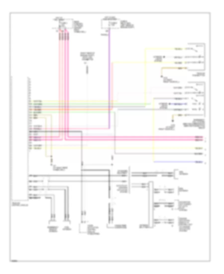
Tele Aid Wiring Diagram, Convertible without D2B Data Bus (1 of 2) for Mercedes-Benz CLK320 2003
List of elements for Tele Aid Wiring Diagram, Convertible without D2B Data Bus (1 of 2) for Mercedes-Benz CLK320 2003:
- (right rear of engine compt) data link connector
- Antenna splitter
- Auto pilot/ command actuation system
- Comand actuation display & control unit (w/ comand actuation) system)
- Ctel antenna
- Emergency backup antenna
- Emergency call system service & breakdown service pushbutton group
- Fuse & relay box (left rear of engine compt)
- Fuse 3 10a
- Fuse 6 7.5a
- Gps antenna
- Hands free microphone
- Hot at all times
- Hot in acc, run or start
- Interior lights system
- Navigation unit & radio (w/ auto pilot system)
- Nca
- Rear fuse box (in trunk, against right wheelwell)
- Standard equipment
- Tele aid control module
- Tele aid pushbutton
- Voice activation control module (if equipped)
- W19 (at right front door sill)
- W7 (at right rear wheelwell)
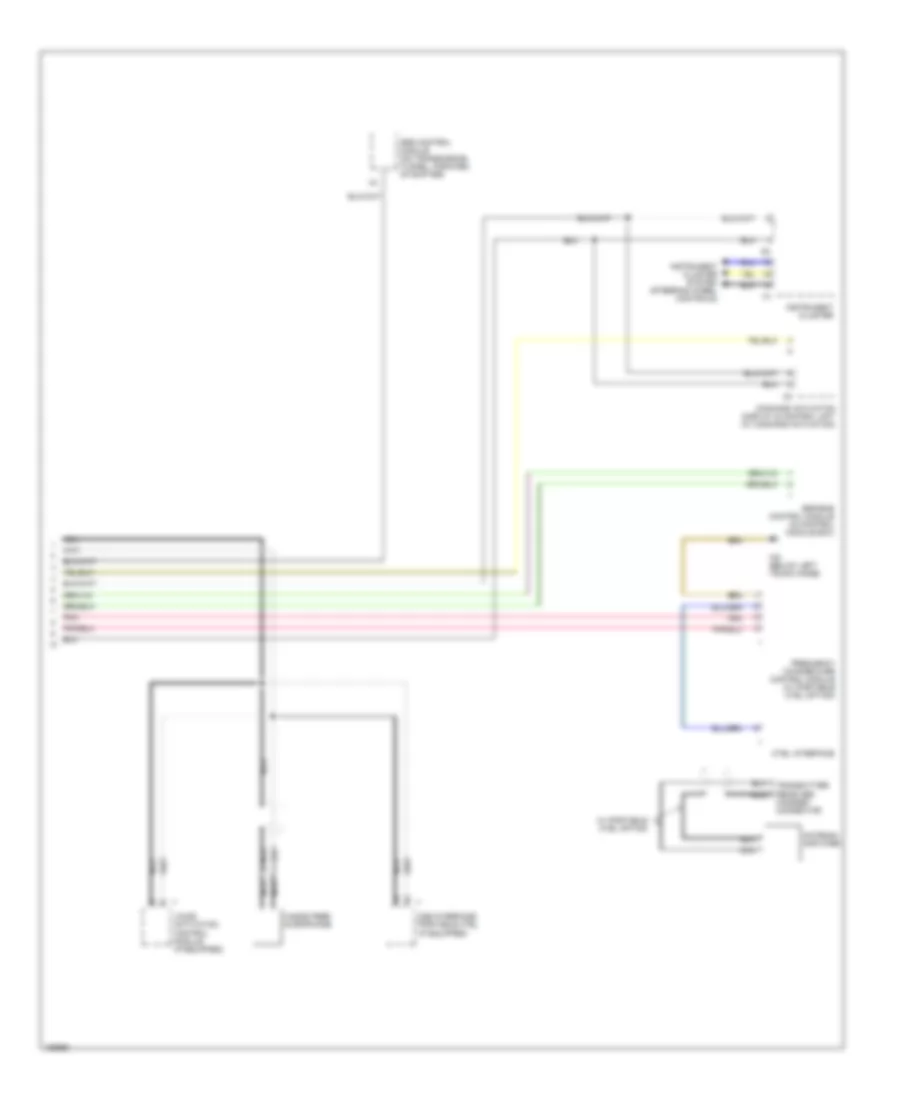
Tele Aid Wiring Diagram, Convertible without D2B Data Bus (2 of 2) for Mercedes-Benz CLK320 2003
List of elements for Tele Aid Wiring Diagram, Convertible without D2B Data Bus (2 of 2) for Mercedes-Benz CLK320 2003:
- (at right rear wheelwell) w7
- Command actuation display & control unit
- Ctel transmitter/ receiver
- Double coil speaker (radio ctel hfs)
- Navigation unit & radio
- Nca
- Radio
- Red
- Srs control module (on transmission tunnel, forward of shifter)
- Tele aid control module
- W/ auto pilot system
- W/ comand actuation
- W/ standard radio
Tele Aid Wiring Diagram, with D2B Data Bus for Mercedes-Benz CLK320 2003
List of elements for Tele Aid Wiring Diagram, with D2B Data Bus for Mercedes-Benz CLK320 2003:
- (at right rear wheelhouse) w7
- 15r
- 58d
- Airbag sig
- Aux. antenna
- C11
- C21
- C23
- C25
- C26
- Can h
- Can l
- Computer data lines system
- Ctel antenna
- D2b
- D2b data bus circuit
- D2b in
- D2b out
- Diag
- Frequency switchover control module
- Front sam control module fuse & relay module (left rear of engine compt)
- Fuse 7.5a
- Gps
- Gps antenna
- Hot at all times
- Info led
- Info sw
- Interior fuse box (left side of dash)
- J10
- Led
- Left front emergency call speaker
- Mb-info & breakdown assistance switch
- Mic +
- Mic -
- Mute
- Navigation system (voice activation circuit)
- Nca
- Pnk
- Radio & navigation unit
- Radio/command operating, display & control unit
- Rap sw
- Rear sam control module fuse & relay module (left side of trunk)
- Rf sw
- Right front emergency call speaker
- Sos led
- Sos pushbutton switch (in overhead control panel control module)
- Sos sw
- Speaker +
- Speaker -
- Tele aid spare antenna
- Tele aid system control module (front center of trunk)
- Telephone interface
- Unlock
- W/ auto pilot circuit
- W/ radio circuit/ command actuation circuit
- W19 (at right doorsill)
- W7 (at right rear wheelhouse)
- Wake up
Tele Aid Wiring Diagram, without D2B Data Bus for Mercedes-Benz CLK320 2003
List of elements for Tele Aid Wiring Diagram, without D2B Data Bus for Mercedes-Benz CLK320 2003:
- (at right rear wheelhouse) w7
- 15r
- 58d
- Airbag sig
- Aux. antenna
- C11
- C21
- C23
- C25
- C26
- Can h
- Can l
- Computer data lines system
- Ctel antenna
- Diag
- Frequency switchover control module
- Front sam control module fuse & relay module (left rear of engine compt)
- Fuse 7.5a
- Gps
- Gps antenna
- Hot at all times
- Info led
- Info sw
- Interior fuse box (left side of dash)
- J10
- Led
- Left front emergency call speaker
- Mb-info & breakdown assistance switch
- Mic +
- Mic -
- Mute
- Navigation system (voice activation circuit)
- Nca
- Pnk
- Radio & navigation unit
- Radio/command operating, display & control unit
- Rap sw
- Rear sam control module fuse & relay module (left side of trunk)
- Rf sw
- Right front emergency call speaker
- Sos led
- Sos pushbutton switch (in overhead control panel control module)
- Sos sw
- Speaker +
- Speaker -
- Tele aid spare antenna
- Tele aid system & d2b telephone transmitter/receiver control module (front center of trunk)
- Telephone interface
- Unlock
- W/ auto pilot circuit
- W/ radio circuit/ command actuation circuit
- W19 (at right doorsill)
- W7 (at right rear wheelhouse)

 Čeština
 Dansk
Dansk Deutsch
 English
 English
 Español
 Suomi
Suomi Français
 Français
 עברית
עברית Hrvatski
 Magyar
 Italiano
 日本語
日本語 한국어
한국어 Nederlands
 Polski
 Português
 Português
 Română
 Русский
 Slovenčina
 Slovenščina
 Svenska
 Türkçe
 中文 (中国)