
 Čeština
 Dansk
Dansk Deutsch
 English
 English
 Español
 Suomi
Suomi Français
 Français
 עברית
עברית Hrvatski
 Magyar
 Italiano
 日本語
日本語 한국어
한국어 Nederlands
 Polski
 Português
 Português
 Română
 Русский
 Slovenčina
 Slovenščina
 Svenska
 Türkçe
 中文 (中国)

SHIFT INTERLOCK
Shift Interlock Wiring Diagram for Volvo V70 2005
List of elements for Shift Interlock Wiring Diagram for Volvo V70 2005:
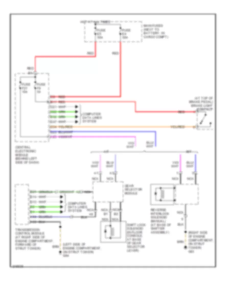

ANTI-THEFTBODY CONTROL MODULESCOMPUTER DATA LINESANTI-LOCK BRAKESCRUISE CONTROLAIR CONDITIONINGCOOLING FANELECTRONIC POWER STEERINGDEFOGGERSELECTRONIC SUSPENSIONENGINE PERFORMANCEHEADLIGHTSGROUND DISTRIBUTIONEXTERIOR LIGHTSINSTRUMENT CLUSTERHORNPOWER DISTRIBUTIONPOWER MIRRORSPOWER DOOR LOCKSMEMORY SYSTEMSINTERIOR LIGHTSNAVIGATIONPOWER WINDOWSPOWER SEATSPOWER TOP/SUNROOFSHIFT INTERLOCKRADIOTRANSMISSIONSUPPLEMENTAL RESTRAINTSWARNING SYSTEMSSTARTING/CHARGINGWIPER/WASHER