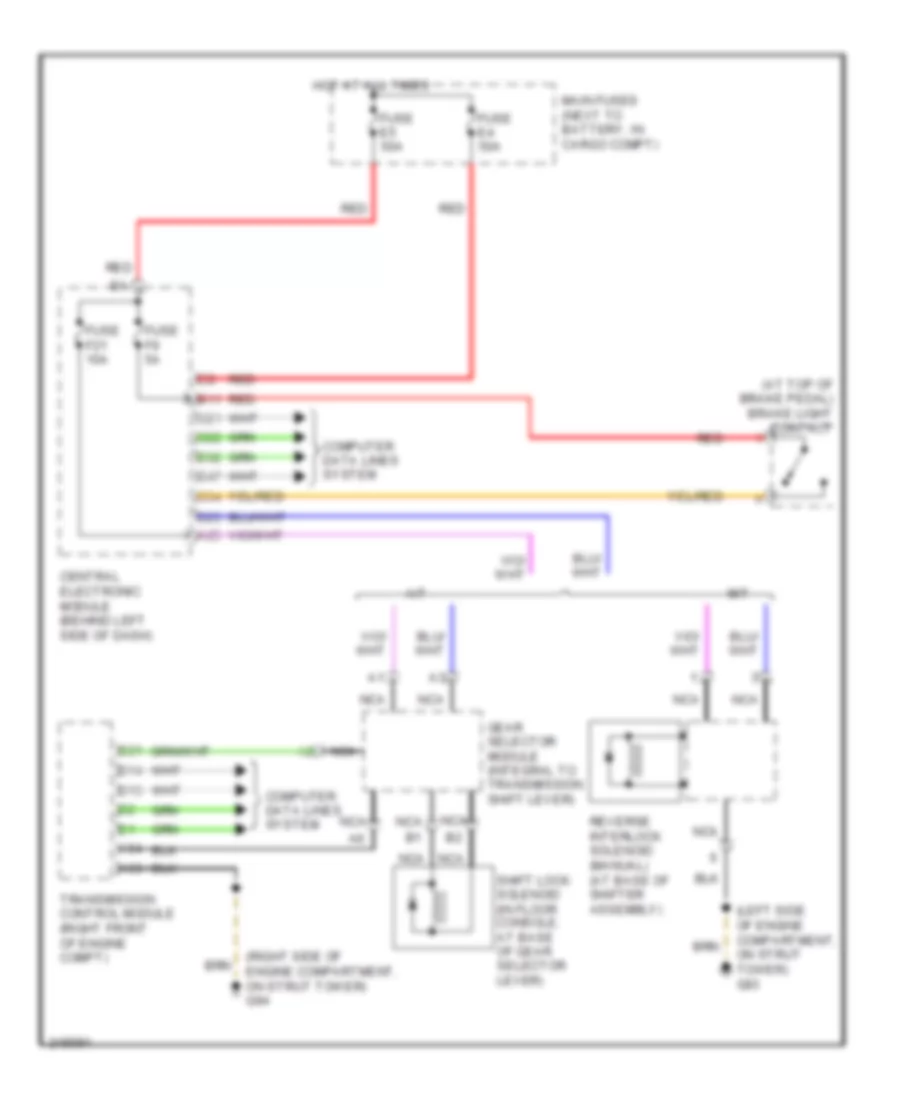
SHIFT INTERLOCK
Shift Interlock Wiring Diagram for Volvo XC90 2006
List of elements for Shift Interlock Wiring Diagram for Volvo XC90 2006:
- (at top of brake pedal) brake light contact
- (left side of engine compartment, on strut tower) g93
- (right side of engine compartment, on strut tower) g94
- A/t
- A25
- A53
- A54
- B11
- B13
- B14
- B21
- C21
- C22
- C34
- Central electronic module (behind left side of dash)
- Computer data lines system
- D23
- D32
- D47
- Fuse e4 50a
- Fuse e5 50a
- Fuse f21 10a
- Fuse f9 5a
- Gear selector module (integral to transmission shift lever)
- Hot at all times
- M/t
- Main fuses (next to battery, in cargo compt)
- Nca
- Red
- Reverse interlock solenoid (manual) (at base of shifter assembly)
- Shift lock solenoid (in floor console, at base of gear selector lever)
- Transmission control module (right front of engine compt)
 Čeština
 Dansk
Dansk Deutsch
 English
 English
 Español
 Suomi
Suomi Français
 Français
 עברית
עברית Hrvatski
 Magyar
 Italiano
 日本語
日本語 한국어
한국어 Nederlands
 Polski
 Português
 Português
 Română
 Русский
 Slovenčina
 Slovenščina
 Svenska
 Türkçe
 中文 (中国)
 Ελληνικά