TRANSMISSION
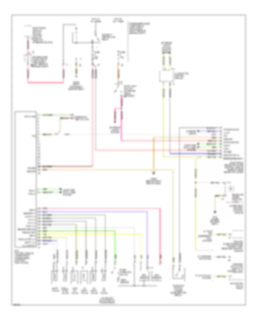
A/T Wiring Diagram, Convertible for Mercedes-Benz CLK320 2002
List of elements for A/T Wiring Diagram, Convertible for Mercedes-Benz CLK320 2002:
- 1-2/ 4-5 valve
- 1-2/4-5 vlv
- 2-3 shift valve
- 2-3 vlv
- 3-4 shift valve
- 3-4 vlv
- Backup sw in
- Backup sw out
- C2 driver's side fuse & relay module box (left rear of engine compt)
- Can (+)
- Can (-)
- Can h
- Can l
- Command actuation display & control unit
- Computer data lines system
- Data line
- Diagnostic test clutch
- Electronic ignition switch control module (right of steering column)
- Electronic selector lever control module (base of gear selector lever)
- Etc control module (under front passenger's footwell foot plate)
- Exterior lights system
- Exterior lights system (backup lamps)
- Fuse 10a
- Ground
- Hot at all times
- Illum
- Illumination control module
- Interior lights
- Kickdown sw
- Kickdown switch (under accelerator pedal)
- Lock up valve
- Lower field control control module
- Modul- ator valve
- Modulator vlv
- Navigation unit & radio
- P/n
- Passenger's side fuse & relay module box (right rear of engine compt)
- Pnk
- Pnk/red
- Polarity protection relay
- Power
- Pwm vlv
- Rpm 2
- Rpm 3
- Rpm sensor
- Selector lever position illum
- Sensor ground
- Sensor v+
- Shift valve
- Shift vlv
- Start interlock switch
- Stop light switch (on brake pedal bracket)
- Stoplamp sw
- Tele aid & d2b telephone transmitter/ receiver control module
- Temp sensor
- Temp/start
- Valve unit (in automatic transmission)
- W/ auto pilot system
- W/ command actuation
- W/ tele aid (emergency call system)
- W16/4 (right component compartment)
- W18 (under driver's seat)
- W29/2 (behind right end of dash)
 Čeština
 Dansk
Dansk Deutsch
 English
 English
 Español
 Suomi
Suomi Français
 Français
 עברית
עברית Hrvatski
 Magyar
 Italiano
 日本語
日本語 한국어
한국어 Nederlands
 Polski
 Português
 Português
 Română
 Русский
 Slovenčina
 Slovenščina
 Svenska
 Türkçe
 中文 (中国)
 Ελληνικά