ANTI-LOCK BRAKES
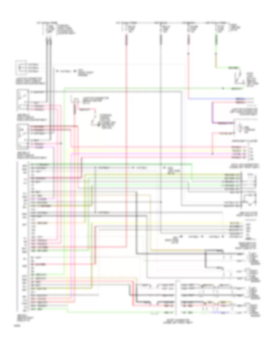
Anti-lock Brake Wiring Diagrams for Toyota Previa LE 1994
List of elements for Anti-lock Brake Wiring Diagrams for Toyota Previa LE 1994:
- A10
- A11
- A12
- A13
- A14
- A15
- A16
- A17
- A18
- A19
- A20
- A21
- A22
- A23
- A24
- A25
- A26
- Abs actuator (right side of i/p)
- Abs ecu (behind right side of i/p)
- Abs fuse 60a
- Abs relay (right side of radiator compartment)
- Abs warning ind
- Ast
- B10
- B11
- B12
- B13
- B14
- B15
- B16
- Bat
- Data link connector 1 (under left front seat)
- Deceleration sensor (4wd) (right side of i/p)
- Ecu-b fuse 15a
- Ecu-ig fuse 15a
- Fl+
- Fl-
- Fr+
- Fr-
- Fss
- Fuse box (right side of radiator compartment)
- G101 (front right fender)
- G201 (right side of i/p)
- G202 (left side of i/p)
- Gauge fuse 10a
- Gnd
- Gs1
- Gs2
- Gst
- Hot at all times
- Hot in run
- Ig1
- Instrument cluster
- Junction connector (behind center of i/p)
- Junction connector (front right side of radiator compartment)
- Junction connector (left side of radiator compartment)
- Left front abs speed sensor
- Left rear abs speed sensor
- Nca
- Parking brake switch (under left center of vehicle)
- Pkb
- Pnk
- R/b #1 (center of i/p)
- Red
- Right front abs speed sensor
- Right rear abs speed sensor
- Rl+
- Rl-
- Rr+
- Rr-
- Rss
- Sfl
- Sfr
- Short connector (under left front seat)
- Srr
- Stop fuse 20a
- Stop light switch (behind left side of i/p)
- Stp
 Čeština
 Dansk
Dansk Deutsch
 English
 English
 Español
 Suomi
Suomi Français
 Français
 עברית
עברית Hrvatski
 Magyar
 Italiano
 日本語
日本語 한국어
한국어 Nederlands
 Polski
 Português
 Português
 Română
 Русский
 Slovenčina
 Slovenščina
 Svenska
 Türkçe
 中文 (中国)
 Ελληνικά