ENGINE PERFORMANCE
2.4L
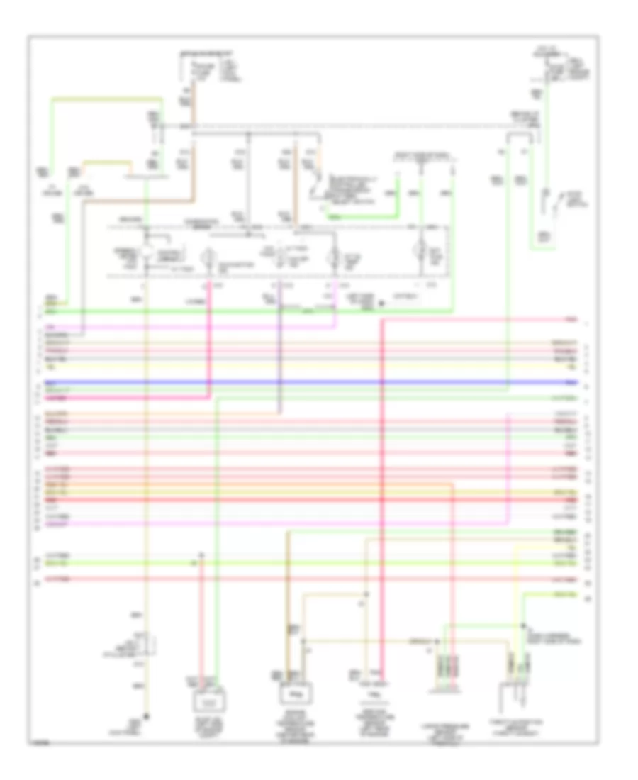
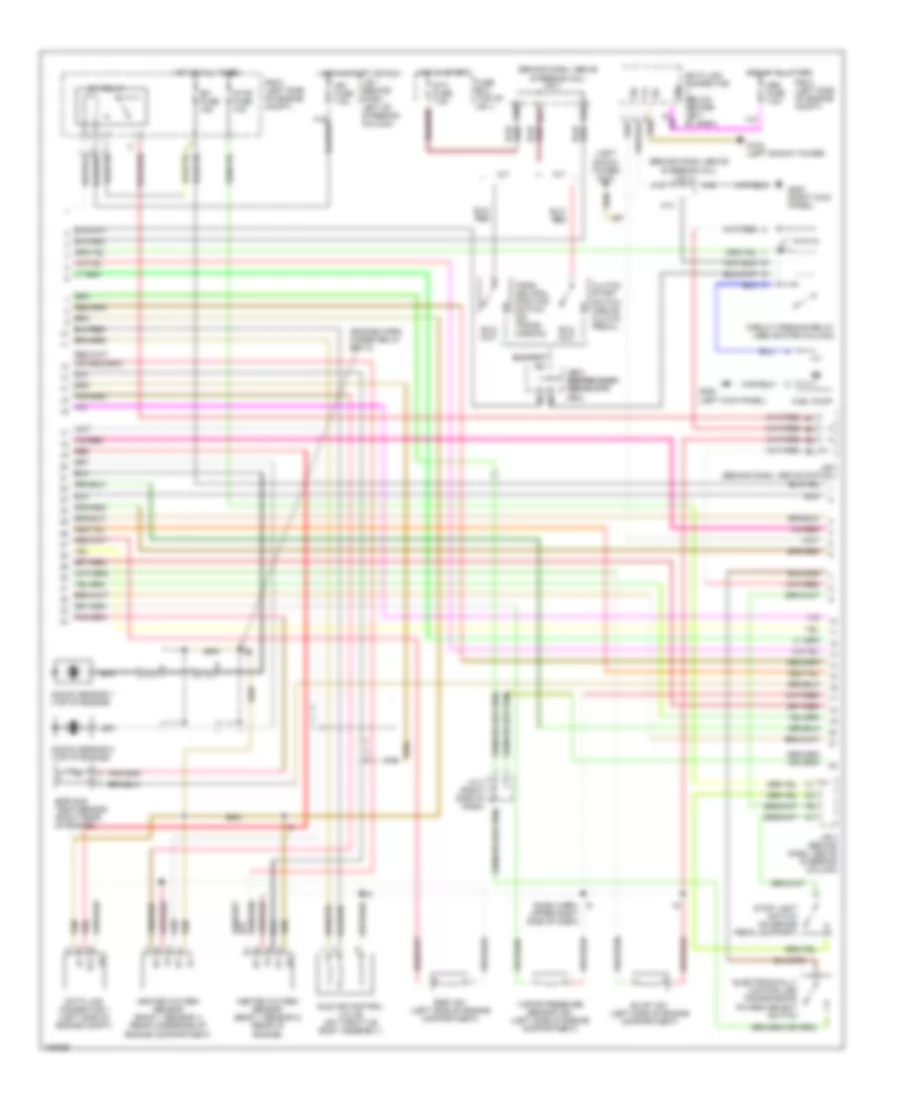
2.4L, Engine Performance Wiring Diagrams (1 of 3) for Toyota Tacoma PreRunner 1998
 https://portal-diagnostov.com/license.html
Automotive Electricians Portal FZCO
Automotive Electricians Portal FZCO
https://portal-diagnostov.com/license.html
https://portal-diagnostov.com/license.html
Automotive Electricians Portal FZCO
Automotive Electricians Portal FZCO
List of elements for 2.4L, Engine Performance Wiring Diagrams (1 of 3) for Toyota Tacoma PreRunner 1998:
- (ignition coil bracket)
- (near throttle body)
- (right side of dash)
- (top left of battery) j/c 9, j/c 10
- 2.4l standard
- 2.7l
- 4wd
- A/t
- A/t indicator switch (park neutral position switch) (on trans)
- A14
- A16
- Acc
- Aci
- Act
- Air conditioning system
- Batt
- Circuit opening relay (behind left side of dash)
- Clutch start switch (above clutch pedal)
- Conn e5
- Conn e6
- Cruise control system
- Data link connector 1 (left side of engine)
- E20
- E21
- E22
- Efi fuse 15a
- Efi relay
- Egr vsv (left side of engine)
- Engine control module (right side of dash)
- F15
- Fuel injectors
- Fuel pump (in fuel tank)
- Fuse box (top of j/b 1)
- G102 (left front fender)
- G113
- G113 (near throttle body)
- G125
- G17
- G201
- G201 (right side of dash)
- G202 (left kick panel)
- G22
- Hot at all times
- Hot in on or start
- I9 (dash harn, right side of dash)
- Ig2
- Ign fuse 7.5a
- Ignition coil and ignitor 1 (left front of eng)
- Ignition coil and ignitor 2 (left front of eng)
- Ignition switch
- J/b 1 (left kick panel)
- J/b 3 (behind dash above strg col)
- J/b 3 (behind dash above strg column)
- J/c 2 (right side of dash)
- Lock
- M/t
- Ne-
- Noise filter (right side of eng compt)
- Nsw
- O/d main switch
- Od1
- Od2
- Oil-w
- Park/neutral position switch (on transmission)
- Pnk
- Ptnk
- Pwr
- R/b 2 (left side of eng compt)
- Red
- Red/
- Sdl
- Sp1
- Sp2+
- Sp2-
- St1
- Sta
- Sta fuse 7.5a
- Start
- Tfn
- Transmission system (2.7l)
- Vehicle speed sensor (on trans)
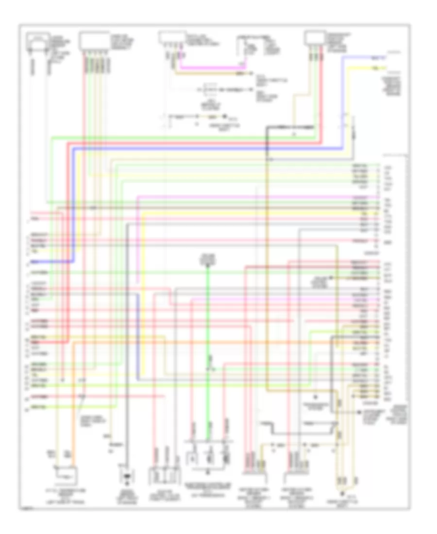
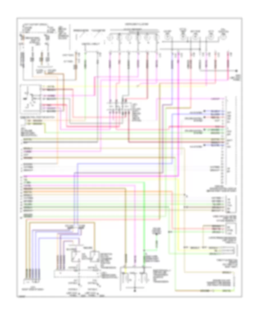
2.4L, Engine Performance Wiring Diagrams (2 of 3) for Toyota Tacoma PreRunner 1998
List of elements for 2.4L, Engine Performance Wiring Diagrams (2 of 3) for Toyota Tacoma PreRunner 1998:
- (behind i/p cluster) j/b 3
- (left side of dash) g202
- (right side of dash) j/c 3
- 2.7l
- A/t oil temp ind.
- C10
- C12
- C13
- Combination meter
- Control circuit
- D10
- D12
- D13
- D16
- D19
- D20
- Ect pwr ind.
- Egr gas temperature sensor (left rear of engine)
- Electronically controlled transmission pattern select switch
- Engine coolant temperature sensor (center rear of engine)
- Evap vsv (left side of engine compt)
- G200 (left kick panel)
- Gauge fuse 10a
- Hot at all times
- Hot in on or start
- I9 (dash harness, right side of dash)
- J/b 1 (left kick panel)
- J/b 3 (behind i/p cluster)
- Malfunction ind.
- O/d off ind.
- Pnk
- R/b 2 (left engine compt)
- Red
- Speedo- meter w/o tach
- Stop fuse 15a
- Stop light switch
- Throttle position sensor (throttle body)
- Vapor pressure sensor (left side of firewall)
- W/ cruise
- W/ tach
- W/o cruise
- W/o tach
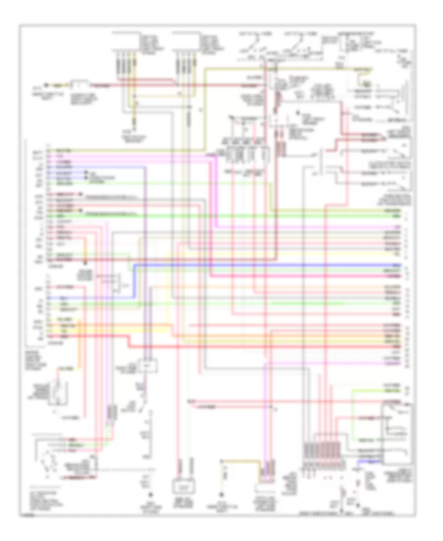
2.4L, Engine Performance Wiring Diagrams (3 of 3) for Toyota Tacoma PreRunner 1998
List of elements for 2.4L, Engine Performance Wiring Diagrams (3 of 3) for Toyota Tacoma PreRunner 1998:
- #10
- #20
- #30
- #40
- (dash harn, right side of dash)
- (near throttle body)
- A/t oil temperature sensor (2.7l) (left side of trans)
- Camshaft position sensor (front of engine)
- Conn e7
- Conn e8
- Crankshaft position sensor (left side of engine)
- Cruise control system
- Data link connector 3 (center of dash)
- E01
- Egr
- Electronic controlled transmission solenoid (2.7l) (on transmission)
- Engine control module (right side of dash)
- Eo2
- Eo3
- Evp
- G113
- G113 (near throttle body)
- G201 (right side of dash)
- Heated oxygen sensor (bank 1 sensor 1) (exhaust system)
- Heated oxygen sensor (bank 1 sensor 2) (exhaust system)
- Hot at all times
- Ht1
- Ht2
- Idle air control valve (throttle body)
- Idlo
- Igf
- Igt1
- Igt2
- Instrument cluster system (tach)
- J/b 3 (behind i/p cluster)
- Knk
- Knock sensor (left front of engine)
- Mass air flow meter (air intake assembly)
- Nca
- Obd fuse 10a
- Oil
- Ox1
- Ox2
- Pnk
- R/b 2 (left engine compt)
- Red
- Rsc
- Rso
- Tac
- Te1
- Tha
- Thg
- Thw
- Tpc
- Transmission system
- Vapor pressure sensor vsv (left side of fire- wall)
- Vcc
- Vta
2.7L
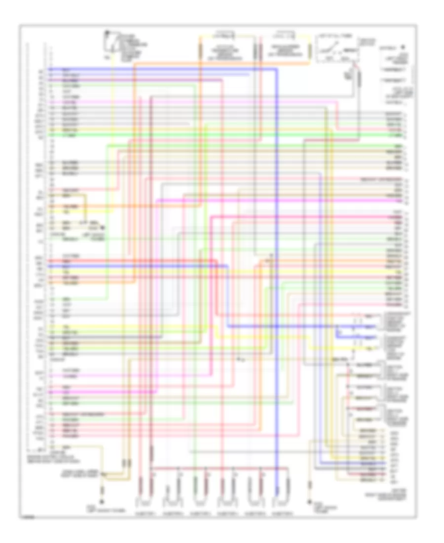
2.7L, Engine Performance Wiring Diagrams (1 of 3) for Toyota Tacoma PreRunner 1998
List of elements for 2.7L, Engine Performance Wiring Diagrams (1 of 3) for Toyota Tacoma PreRunner 1998:
- (ignition coil bracket)
- (near throttle body)
- (right side of dash)
- (top left of battery) j/c 9, j/c 10
- 2.4l standard
- 2.7l
- 4wd
- A/t
- A/t indicator switch (park neutral position switch) (on trans)
- A14
- A16
- Acc
- Aci
- Act
- Air conditioning system
- Batt
- Circuit opening relay (behind left side of dash)
- Clutch start switch (above clutch pedal)
- Conn e5
- Conn e6
- Cruise control system
- Data link connector 1 (left side of engine)
- E20
- E21
- E22
- Efi fuse 15a
- Efi relay
- Egr vsv (left side of engine)
- Engine control module (right side of dash)
- F15
- Fuel injectors
- Fuel pump (in fuel tank)
- Fuse box (top of j/b 1)
- G102 (left front fender)
- G113
- G113 (near throttle body)
- G125
- G17
- G201
- G201 (right side of dash)
- G202 (left kick panel)
- G22
- Hot at all times
- Hot in on or start
- I9 (dash harn, right side of dash)
- Ig2
- Ign fuse 7.5a
- Ignition coil and ignitor 1 (left front of eng)
- Ignition coil and ignitor 2 (left front of eng)
- Ignition switch
- J/b 1 (left kick panel)
- J/b 3 (behind dash above strg col)
- J/b 3 (behind dash above strg column)
- J/c 2 (right side of dash)
- Lock
- M/t
- Ne-
- Noise filter (right side of eng compt)
- Nsw
- O/d main switch
- Od1
- Od2
- Oil-w
- Park/neutral position switch (on transmission)
- Pnk
- Ptnk
- Pwr
- R/b 2 (left side of eng compt)
- Red
- Red/
- Sdl
- Sp1
- Sp2+
- Sp2-
- St1
- Sta
- Sta fuse 7.5a
- Start
- Tfn
- Transmission system (2.7l)
- Vehicle speed sensor (on trans)
2.7L, Engine Performance Wiring Diagrams (2 of 3) for Toyota Tacoma PreRunner 1998
List of elements for 2.7L, Engine Performance Wiring Diagrams (2 of 3) for Toyota Tacoma PreRunner 1998:
- (behind i/p cluster) j/b 3
- (left side of dash) g202
- (right side of dash) j/c 3
- 2.7l
- A/t oil temp ind.
- C10
- C12
- C13
- Combination meter
- Control circuit
- D10
- D12
- D13
- D16
- D19
- D20
- Ect pwr ind.
- Egr gas temperature sensor (left rear of engine)
- Electronically controlled transmission pattern select switch
- Engine coolant temperature sensor (center rear of engine)
- Evap vsv (left side of engine compt)
- G200 (left kick panel)
- Gauge fuse 10a
- Hot at all times
- Hot in on or start
- I9 (dash harness, right side of dash)
- J/b 1 (left kick panel)
- J/b 3 (behind i/p cluster)
- Malfunction ind.
- O/d off ind.
- Pnk
- R/b 2 (left engine compt)
- Red
- Speedo- meter w/o tach
- Stop fuse 15a
- Stop light switch
- Throttle position sensor (throttle body)
- Vapor pressure sensor (left side of firewall)
- W/ cruise
- W/ tach
- W/o cruise
- W/o tach
2.7L, Engine Performance Wiring Diagrams (3 of 3) for Toyota Tacoma PreRunner 1998
List of elements for 2.7L, Engine Performance Wiring Diagrams (3 of 3) for Toyota Tacoma PreRunner 1998:
- #10
- #20
- #30
- #40
- (dash harn, right side of dash)
- (near throttle body)
- A/t oil temperature sensor (2.7l) (left side of trans)
- Camshaft position sensor (front of engine)
- Conn e7
- Conn e8
- Crankshaft position sensor (left side of engine)
- Cruise control system
- Data link connector 3 (center of dash)
- E01
- Egr
- Electronic controlled transmission solenoid (2.7l) (on transmission)
- Engine control module (right side of dash)
- Eo2
- Eo3
- Evp
- G113
- G113 (near throttle body)
- G201 (right side of dash)
- Heated oxygen sensor (bank 1 sensor 1) (exhaust system)
- Heated oxygen sensor (bank 1 sensor 2) (exhaust system)
- Hot at all times
- Ht1
- Ht2
- Idle air control valve (throttle body)
- Idlo
- Igf
- Igt1
- Igt2
- Instrument cluster system (tach)
- J/b 3 (behind i/p cluster)
- Knk
- Knock sensor (left front of engine)
- Mass air flow meter (air intake assembly)
- Nca
- Obd fuse 10a
- Oil
- Ox1
- Ox2
- Pnk
- R/b 2 (left engine compt)
- Red
- Rsc
- Rso
- Tac
- Te1
- Tha
- Thg
- Thw
- Tpc
- Transmission system
- Vapor pressure sensor vsv (left side of fire- wall)
- Vcc
- Vta
3.4L
3.4L, Engine Performance Wiring Diagrams (1 of 3) for Toyota Tacoma PreRunner 1998
List of elements for 3.4L, Engine Performance Wiring Diagrams (1 of 3) for Toyota Tacoma PreRunner 1998:
- (dash harn, upper right side of dash)
- (left shock tower)
- A/t fluid temperature sensor (on transmission)
- Acc
- Camshaft position sensor (top front of engine)
- Conn e6
- Conn e7
- Conn e8
- Crankshaft position sensor (front of engine)
- E01
- E02
- E03
- Egr
- Engine control module (behind right side of dash)
- Evp
- Ext
- G100 (left front fender)
- G102
- G102 (left shock tower)
- Gnd
- Hot at all times
- Ht1
- Ht2
- Igc1
- Igc2
- Igc3
- Igf
- Igniter (right side of engine compartment)
- Ignition coil 1 (right side of engine)
- Ignition coil 2 (right side of engine)
- Ignition coil 3 (right side of engine)
- Ignition switch
- Igt1
- Igt2
- Igt3
- Injector 1
- Injector 2
- Injector 3
- Injector 4
- Injector 5
- Injector 6
- J/c 9, j/c 10 (left side of eng compt)
- Knk1
- Knk2
- Lock
- Ne+
- Ne-
- Nsw
- Oil
- Oil-w
- Ox1
- Ox2
- Power steering oil pressure switch (on power steering pump)
- Psw
- Ptnk
- Pwr
- Red
- Rsc
- Rso
- Run
- Sp2+
- Sp2-
- Sta
- Start
- Te1
- Tha
- Thg
- Thw
- Tpc
- Vehicle speed sensor (on transmission)
- Vta
3.4L, Engine Performance Wiring Diagrams (2 of 3) for Toyota Tacoma PreRunner 1998
List of elements for 3.4L, Engine Performance Wiring Diagrams (2 of 3) for Toyota Tacoma PreRunner 1998:
- (behind dash, above
- (dash harn, upper right side of dash)
- (engine harn, under relay box 2)
- (left shock tower) g102
- A/t
- A14
- A15
- A16
- Circuit opening relay (above strg column)
- Clutch start switch (above clutch pedal)
- Data link connector (below center left of dash)
- Data link connector 1 (left side of engine compt)
- E20
- E21
- E22
- Efi fuse 15a
- Efi relay
- Egr gas temp sensor (right rear of engine)
- Egr vsv (left side of engine compartment)
- Electronically controlled transmission patern select switch
- Evap vsv (left side of engine compartment)
- Fuel pump
- Fuse box (top of j/b 1)
- G102 (left shock tower)
- G200 (left kick panel)
- G203 (right kick panel)
- Heated oxygen sensor (bank 1 sensor 1) (rear underside of engine compartment)
- Heated oxygen sensor (bank 1 sensor 2) (rear of engine)
- Hot at all times
- Hot in start
- Hot in start or run
- Idle air control valve (on throttle body assembly)
- Ign fuse 7.5a
- J/b 1 (behind dash, left of steering column)
- J/b 3
- J/b 3 (behind dash, above steering column)
- J/b 3 (behind dash, above str col)
- J/b 3 j/b 3 (behind dash (behind dash above str above str col) col)
- J/c 3 (right side of dash)
- Knock sensor 1 (top of engine)
- Knock sensor 2 (top of engine)
- M/t
- Obd fuse 7.5a
- Park/ neutral position switch (on trans- mission)
- R/b 2 (left side of engine compt)
- Red
- Sdl
- Sil
- Sta fuse 7.5a
- Steering col)
- Stop fuse 10a
- Stop light switch (on brake pedal support)
- Te1
- Vapor pressure sensor vsv (left side of engine compartment)
3.4L, Engine Performance Wiring Diagrams (3 of 3) for Toyota Tacoma PreRunner 1998
List of elements for 3.4L, Engine Performance Wiring Diagrams (3 of 3) for Toyota Tacoma PreRunner 1998:
- (behind dash, right of strg col) j/b 3
- (dash harn, upper right side of dash)
- (left kick panel)
- (w tach)
- (w tach) (w/o tach)
- (w/o tach)
- A/c system
- A/t oil temp ind
- A/t p ind
- Ac1
- Act
- Batt
- C10
- C11
- C12
- C13
- Cig fuse 15a
- Column shift
- Conn e5
- Control circuit
- Cruise control system
- D13
- D16
- D18
- D19
- D20 d16
- Detection switch (transfer neutral position) (on transmission)
- Ect pwr ind
- Electronically controlled transmission solenoid (on transmission)
- Engine control module (behind right side of dash)
- Engine coolant temperature sensor (top front of engine)
- F12
- F16
- Floor shift
- G17
- G200
- G200 (left kick panel)
- G22
- Gauge fuse 10a
- H11
- H12
- H13
- H20
- H22
- Hot in start or run
- Idlo
- Instrument cluster
- J/b 1 (behind dash, left of steering column)
- J/b 3 (behind dash, above str col)
- J/b 3 (w/ column shift) (behind dash, above str col)
- J/b 3 (w/ cruise) (behind dash, above str col)
- J/c 2 (right side of dash)
- Mal- function ind
- Mass air flow meter (part of air intake assembly)
- O/d main switch
- O/d off ind
- Od1
- Od2
- Park/neutral position switch
- Pnk
- Ptnk
- Sil
- Sp1
- Speedometer
- Tachometer
- Tha
- Throttle position sensor (on throttle body assy)
- Vapor pressure sensor (left side of firewall)
- Vcc
- W/ column shift

 Čeština
 Dansk
Dansk Deutsch
 English
 English
 Español
 Suomi
Suomi Français
 Français
 עברית
עברית Hrvatski
 Magyar
 Italiano
 日本語
日本語 한국어
한국어 Nederlands
 Polski
 Português
 Português
 Română
 Русский
 Slovenčina
 Slovenščina
 Svenska
 Türkçe
 中文 (中国)