ACTIVE BODYWORKS
Active Bodyworks Wiring Diagram, Early Production for BMW ActiveHybrid 3 2014
 https://portal-diagnostov.com/license.html
Automotive Electricians Portal FZCO
Automotive Electricians Portal FZCO
https://portal-diagnostov.com/license.html
https://portal-diagnostov.com/license.html
Automotive Electricians Portal FZCO
Automotive Electricians Portal FZCO
List of elements for Active Bodyworks Wiring Diagram, Early Production for BMW ActiveHybrid 3 2014:
- (on left rear wheelwell) z10 8b
- (right side of rear compt) trailer module
- Fully automatic towing hitch
- Fully automatic towing hitch button
- Fully automatic towing hitch drive
- Fuse 20a
- Hot w/ terminal 30b relay energized
- Rear fuse holder (right side of rear compt)
- Red
- Trailer socket switch
- X268 1b
- X269 1b
- Z10 8b (on left rear wheelwell)
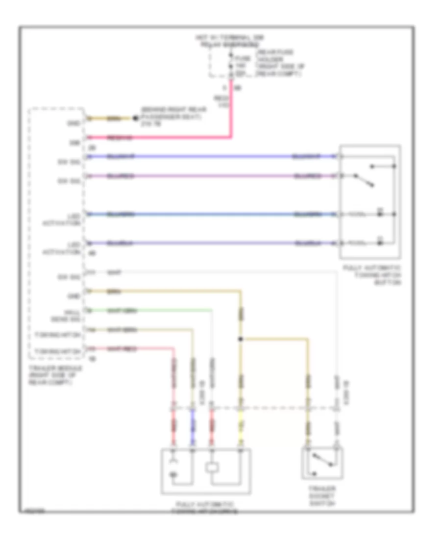
Active Bodyworks Wiring Diagram, Late Production for BMW ActiveHybrid 3 2014
List of elements for Active Bodyworks Wiring Diagram, Late Production for BMW ActiveHybrid 3 2014:
- (behind right rear passenger seat) z10 7b
- 30b
- Fully automatic towing hitch button
- Fully automatic towing hitch drive
- Fuse 20a
- Gnd
- Hall sens sig
- Hot w/ terminal 30b relay energized
- Led activation
- Rear fuse holder (right side of rear compt)
- Red
- Sw sig
- Towing hitch
- Trailer module (right side of rear compt)
- Trailer socket switch
- X268 1b
- X269 1b
AIR CONDITIONING
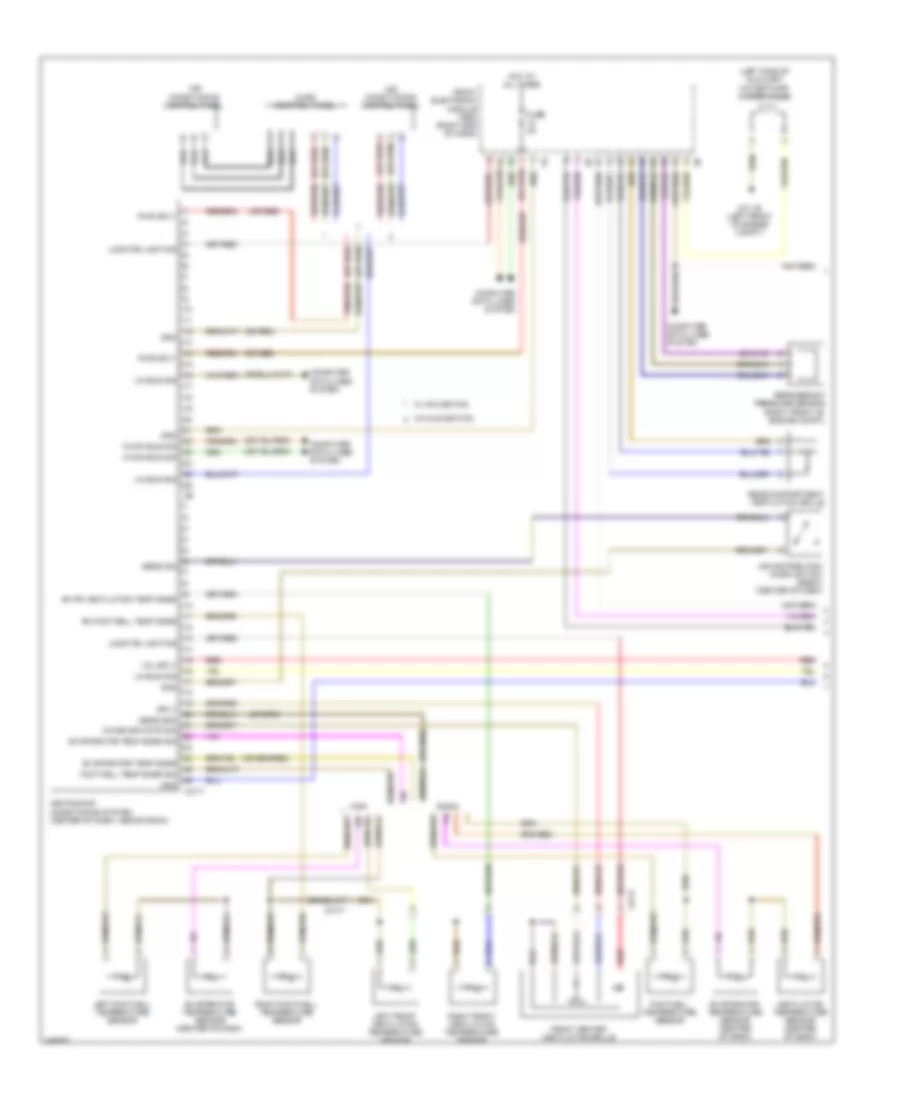
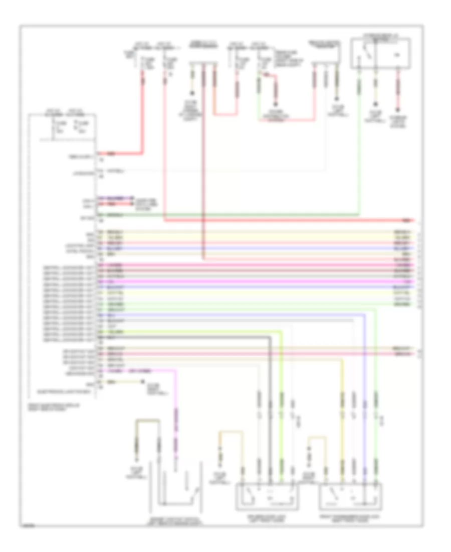
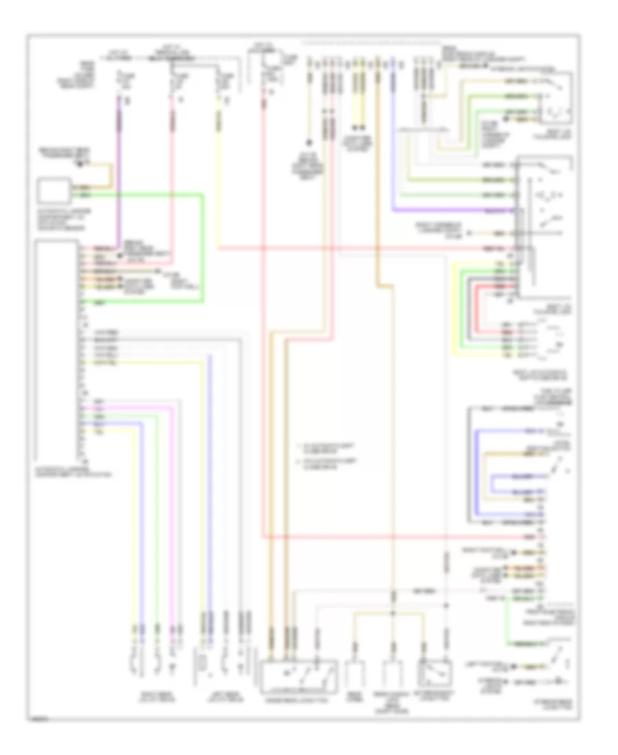
Automatic A/C Wiring Diagram (1 of 4) for BMW ActiveHybrid 3 2014
List of elements for Automatic A/C Wiring Diagram (1 of 4) for BMW ActiveHybrid 3 2014:
- (left side of auxiliary water pump) water valve
- (or red)
- Air conditioning control panel
- Air distribution micro switch (basic) (center of dash)
- Audio control panel
- Basic
- Computer data lines system
- Evaporator temp snsr
- Evaporator temp snsr sig
- Evaporator temperature sensor (center of dash)
- Footwell temp snsr sig
- Footwell temperature sensor
- Front center ventilation grille
- Front electronic module (fem) (right end of dash)
- Fuse 5a
- Gnd
- Heating/air conditioning system (center of dash, above radio)
- High
- Hot at all times
- K-can bus sig
- Left footwell temperature sensor
- Left front ventilation temperature sensor
- Lin bus sig
- Locator lighting
- Mixing sir cntr sig
- Pwr sply
- Rear compartment ventilation grille
- Red
- Refrigerant pressure sensor (right front of engine compt)
- Rh footwell temp snsr
- Rh fr ventilation temp snsr
- Right footwell temperature sensor
- Right front ventilation temperature sensor
- Sens gnd
- Sens sig
- Sply
- Ventilation temperature sensor (center of dash)
- Vol sply
- W/ navigation
- W/o navigation
- X4711
- X4717
- Z10 1b (left front of engine compt)
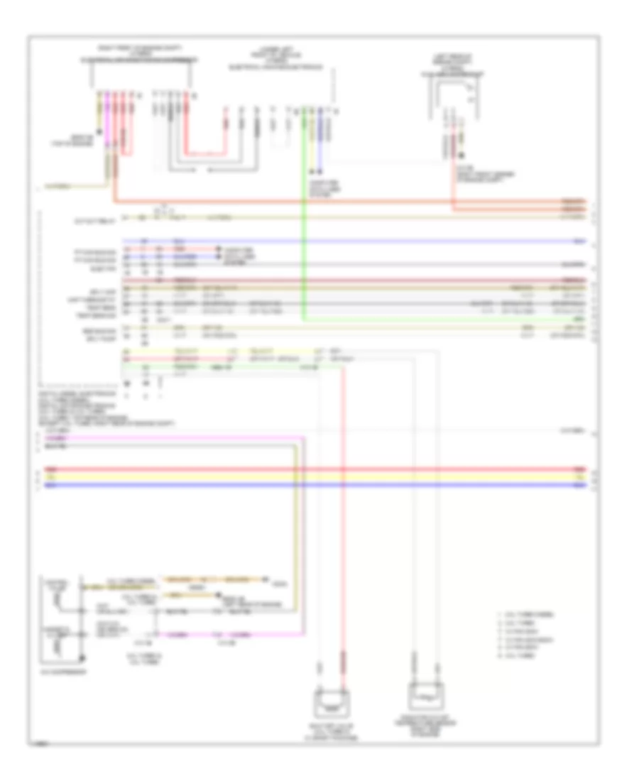
Automatic A/C Wiring Diagram (2 of 4) for BMW ActiveHybrid 3 2014
List of elements for Automatic A/C Wiring Diagram (2 of 4) for BMW ActiveHybrid 3 2014:
- (left rear of engine compt) (hybrid) auxiliary water pump
- (right front of engine compt) (hybrid) electrical air conditioning compressor
- (under left front of vehicle) (hybrid) electrical machine electronics
- 2.0l turbo
- 2.0l turbo & 3.0l turbo
- 2.0l turbo diesel
- 3.0l turbo
- A/c compressor
- Bsd bus sig
- Computer data lines system
- Control valve
- Cut-out relay
- Digital diesel electronics (2.0l turbo diesel) digital motor electronics (2.0l turbo & 3.0l turbo) (2.0l turbo: top rear of engine) (except 2.0l turbo: right rear of engine compt)
- Elec fan
- Magnetic clutch
- Map thermostat
- Pt-can bus sig
- Radiator outlet temperature sensor (right side of engine)
- Red
- Shield
- Shut-off valve (3.0l turbo & w/ sport package)
- Sply map
- Sply pump
- Temp sens
- Temp sens sig
- W/ fan 300w
- W/ fan 400w/600w
- W/ fan 850w
- X13 1b
- X13 3b
- X2042
- X2411
- X60681
- X664 1b
- Z10 2b (right front corner of engine compt)
- Z6000 2b (top of engine)
- Z6000 4b (left rear of engine)
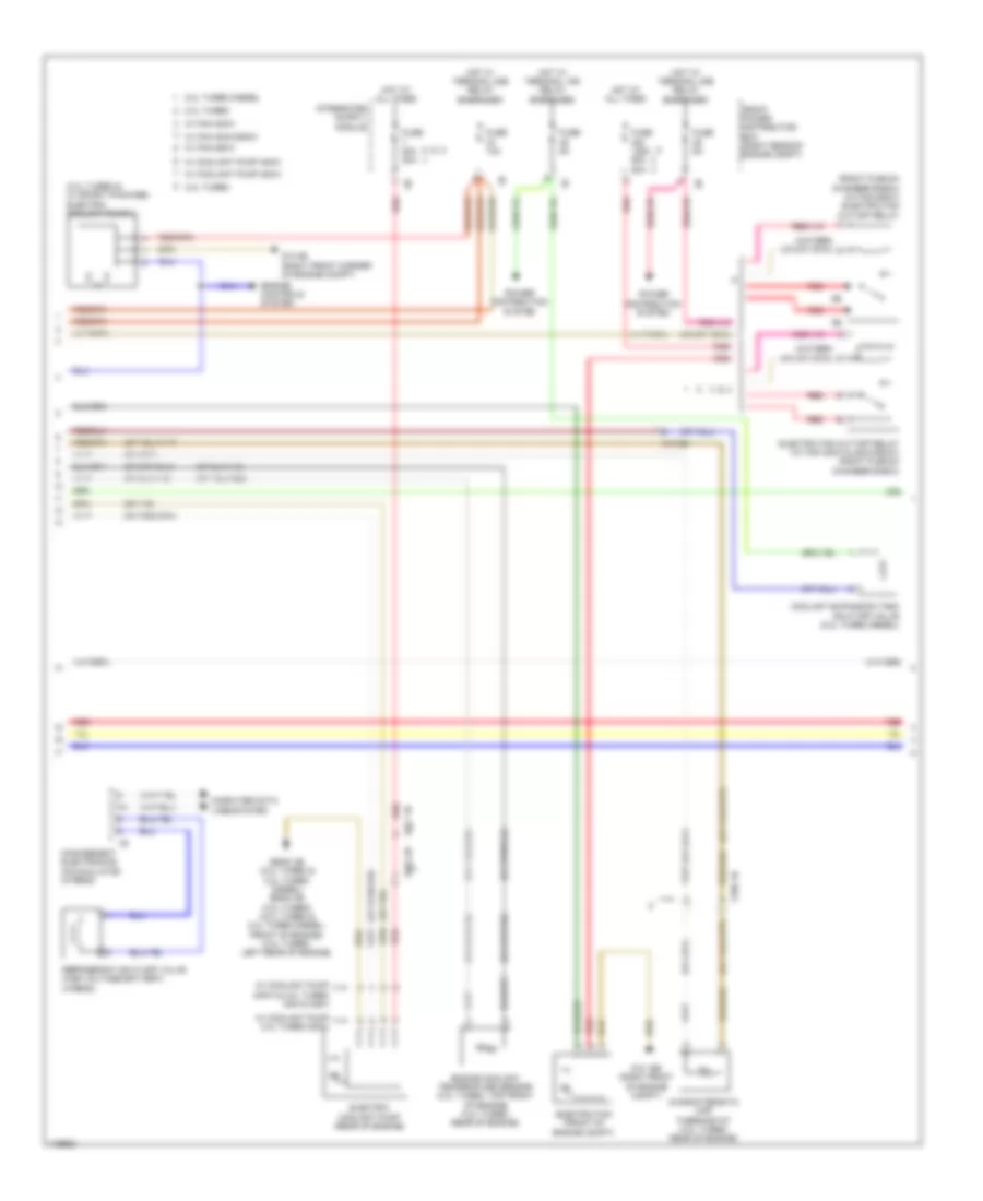
Automatic A/C Wiring Diagram (3 of 4) for BMW ActiveHybrid 3 2014
List of elements for Automatic A/C Wiring Diagram (3 of 4) for BMW ActiveHybrid 3 2014:
- (3.0l turbo & w/ sport package) electric coolant pump 2
- (right plenum chamber e-box) (w/ fan 850w) electric fan cut-off relay
- 2.0l turbo
- 2.0l turbo diesel
- 3.0l turbo
- Characteristic map thermostat (3.0l turbo: rear of engine)
- Computer data lines system
- Coolant expansion tank shut-off valve (2.0l turbo diesel)
- Electric coolant pump (rear of engine)
- Electric fan (front of engine compt)
- Electric fan cut-off relay (w/ fan 300w & 400w/600w) (right plenum chamber e-box)
- Engine controls system
- Engine coolant temperature sensor (2.0l turbo: top front of engine) (3.0l turbo: rear of engine)
- Front power distribution box (right rear of engine compt)
- Fuse 10a
- Fuse 125a 50a 80a
- Fuse 50a 30a
- Fuse 5a
- Hot at all times
- Hot w/ terminal 15n relay energized
- Hot w/ terminal 30b relay energized
- Management electronics accumulator (hybrid)
- Power distribution system
- Red
- Refrigerant shut-off valve (high voltage battery) (hybrid)
- W/ coolant pump 2.0l turbo 200w
- W/ coolant pump 200w
- W/ coolant pump 400w
- W/ coolant pump 400w & 3.0l turbo 335i & 335xi
- W/ fan 300w
- W/ fan 400w/600w
- W/ fan 850w
- X13 3b
- X664 2b
- X671 1b
- X705 1b
- Z10 15b (right front of engine compt)
- Z10 2b (right front corner of engine compt)
- Z6000 3b (2.0l turbo & 2.0l turbo diesel) z6000 4b (3.0l turbo) (2.0l turbo & 2.0l turbo diesel: front of engine) (3.0l turbo: left rear of engine)
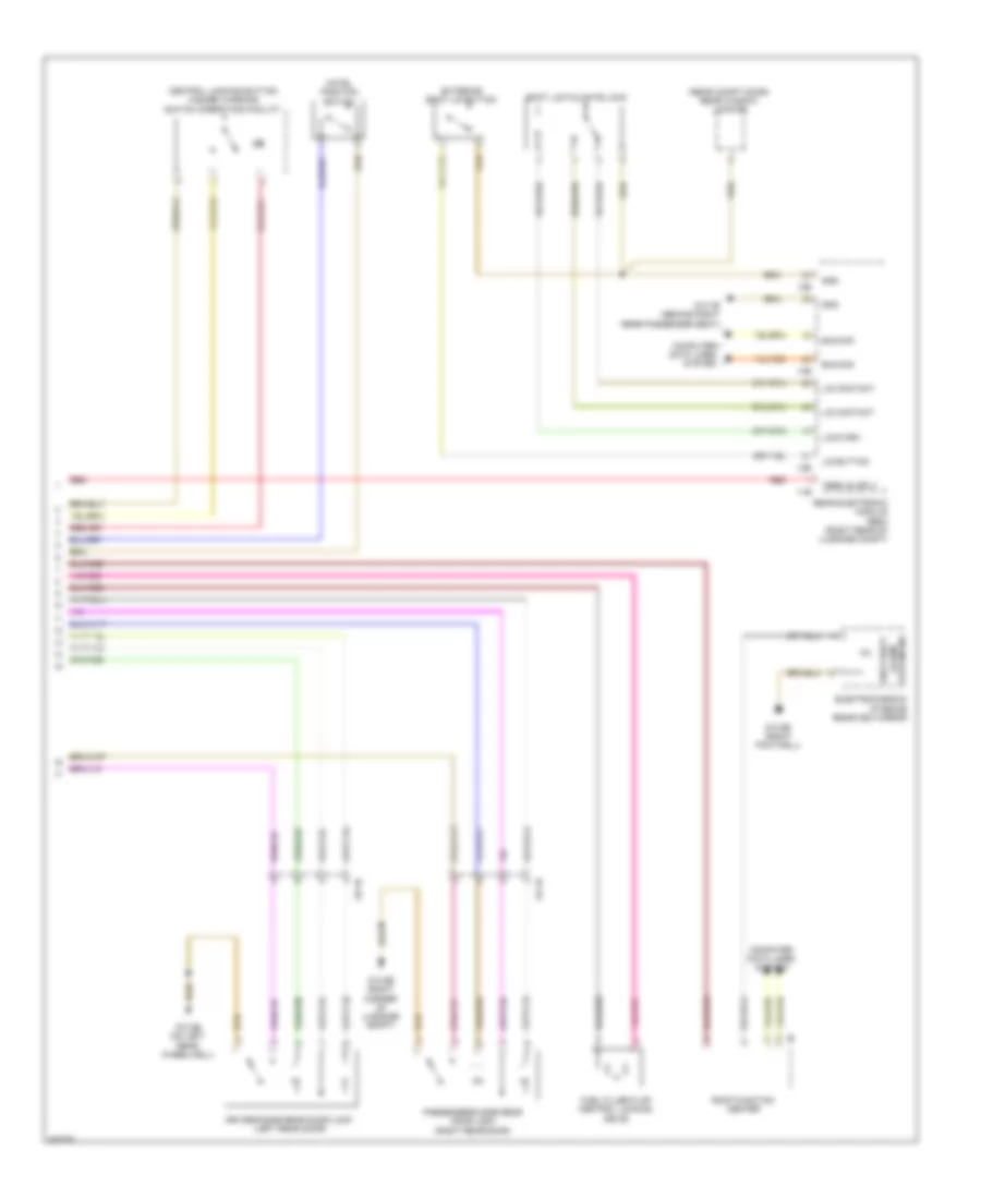
Automatic A/C Wiring Diagram (4 of 4) for BMW ActiveHybrid 3 2014
List of elements for Automatic A/C Wiring Diagram (4 of 4) for BMW ActiveHybrid 3 2014:
- (under right side of dash)
- 10b
- Air distribution flap motor (basic) (center of dash, above radio)
- Auc sensor (right rear of engine compt)
- Basic
- Blower motor (behind right side of dash)
- Blower output stage
- Computer data lines system
- Defroster flap motor (high) (behind right side of dash)
- Fresh air flap motor (right side of dash)
- Front electric auxiliary heater
- Front power distribution box (right rear of engine compt)
- Front refrigerant shut-off valve (hybrid)
- Fuse 100a
- Fuse 10a
- Fuse 40a
- Fuse 5a
- High
- Hot at all times
- Hot w/ terminal 15n relay energized
- Hot w/ terminal 30b relay energized
- Left front footwell flap motor (high)
- Left front stratification flap motor (high) (left side of dash)
- Left mixing flap drive (high)
- Mixing flap drive (basic)
- Rain lights/ condensation/ solar sensor (solar sensor: top center of dash) condensation: center of windshield)
- Rear compartment flap motor (high)
- Red
- Right front footwell flap motor (high)
- Right front stratification flap motor (high)
- Right mixed air flap motor (high) (center of dash, above radio)
- X04000
- X4712
- Z10 5b (right footwell)
- Z10 6b (right footwell)
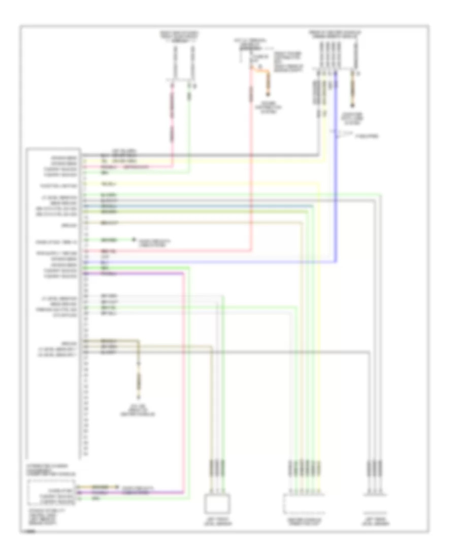
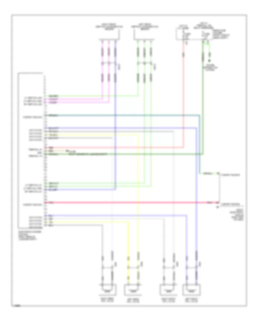
ANTI-LOCK BRAKES
Anti-lock Brakes Wiring Diagram for BMW ActiveHybrid 3 2014
List of elements for Anti-lock Brakes Wiring Diagram for BMW ActiveHybrid 3 2014:
- (top of brake pedal assembly) (hybrid) brake pedal travel sensor
- (under center console) integrated chassis management
- Brake fluid level switch (left rear of engine compt)
- Brake light switch (under left side of dash)
- Bus sig flexray
- Center console control panel
- Computer data lines system
- Distribution system
- Dtc button sig
- Dynamic stability control (dsc) (left rear of engine compt)
- Flexray bus sig
- Front electronic module (right end of dash)
- Front power distribution box (right rear of engine compt)
- Funch light
- Fuse 30a
- Fuse 40a
- Fuse 5a
- Gnd
- Hot at all times
- Hot w/ terminal 30b relay energized
- Interior lights system
- Left front brake pad wear sensor (behind left front wheel)
- Left front wheel speed sensor (left front wheel)
- Left rear wheel speed sensor (behind left rear wheel)
- Nca
- Parking brake warning switch (under center console)
- Power
- Right front wheel speed sensor (behind right front wheel)
- Right rear brake pad wear sensor (right rear wheel)
- Right rear wheel speed sensor (behind right rear wheel)
- Sig brk sw
- Snsr sig
- Spd sig
- Steering column switch cluster
- Sw sig
- Sw sig parking brk
- Terminal 30
- Terminal 30b
- Volt sply
- Wake up sig
- Warning sig
- Wear sig
- Z10 21b (left rear of engine compt)
- Z10 4b (left footwell)
ANTI-THEFT
Access/Start Wiring Diagram (1 of 2) for BMW ActiveHybrid 3 2014
List of elements for Access/Start Wiring Diagram (1 of 2) for BMW ActiveHybrid 3 2014:
- (right corner of luggage compt) z10 9b
- 12b
- 13b
- 14b
- 81g
- Aerail sig
- Aerial sig
- Anti-theft alarm system ind
- Bonnet contact switch (left rear of engine compt)
- Boot lid/ tailgate lock (sedan)
- Boot lid/ tailgate lock (sports wagon & gran turismos)
- Can h
- Can l
- Clutch mod
- Clutch switch module (m/t) (under left side of dash)
- Comfort access
- Comfort access 4b
- Computer data lines system
- Dr cont sig
- Drivers door lock (left front door)
- Electrochromic interior rearview mirror
- Front center console interior aerial
- Front electronic module (right end of dash)
- Front passenger door lock (right front door)
- Fuse 125a
- Fuse 5a
- Fuse box
- Gnd
- Hot at all times
- Hot w/ bi-stable relay energized
- Interior lights system
- Lin bus sig
- Mechanism sig
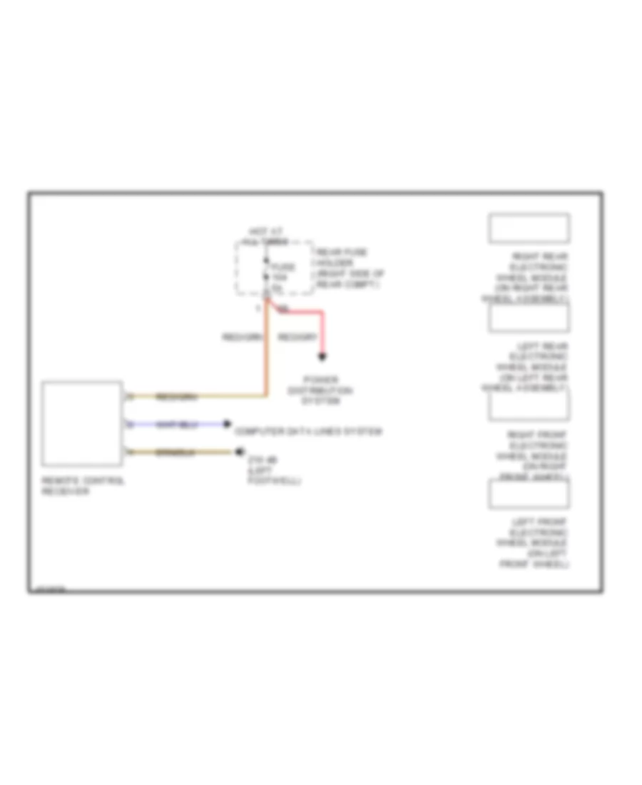
- Power distribution system
- Pwr sply
- Rear center console interior aerial
- Rear drivers side door lock (left rear door)
- Rear electronic module (rem) (right rear of luggage compt)
- Rear fuse holder (right side of rear compt)
- Rear passenger's side door lock (right rear door)
- Red
- Remote control receiver
- Roof function center
- Sig
- Siren w/ tilt alarm sensor
- Sw sig
- Ter 15 sply
- Term 15 sply
- W/ automatic soft close system
- W/o automatic soft close system
- X28 1b
- X5 1b
- X8 1b
- X9 1b
- Z10 3b (left footwell)
- Z10 4b (left footwell)
- Z10 5b (right footwell)
- Z10 6b (right footwell)
- Z10 7b (behind right rear passenger seat)
- Z10 8b (on left rear wheelwell)
- Z10 9b (right corner of luggage compt)
Access/Start Wiring Diagram (2 of 2) for BMW ActiveHybrid 3 2014
List of elements for Access/Start Wiring Diagram (2 of 2) for BMW ActiveHybrid 3 2014:
- (on steering column) electric steering lock
- (or red)
- (right footwell)
- Aerial sig
- Bumper aerial
- Computer data lines system
- Driver electronic outer door handle module
- Driver side external aerial
- Front electronic module (right end of dash)
- Front passenger side external aerial
- Ground
- Groung
- Led act
- Lin bus sig
- Luggage compartment aerial
- Passenger electronic outer door handle module
- Ring aerial
- Sig
- Signal shift
- Start sig
- Start stop
- Start-stop button
- Steering column cluster switch
- Terminal 30
- W/o automatic engine start/stop function
- X28 1b
- X5 1b
- Z10 3b (left footwell)
- Z10 5b
Anti-theft & Central Locking Wiring Diagram (1 of 2) for BMW ActiveHybrid 3 2014
List of elements for Anti-theft & Central Locking Wiring Diagram (1 of 2) for BMW ActiveHybrid 3 2014:
- Bonnet contact switch (left rear of engine compt)
- Can h
- Can l
- Central locking drv act
- Computer data lines system
- Contact sig
- Dr contact sig
- Driver's door lock (left front door)
- Electronics junction box
- Front electronic module (right end of dash)
- Front passenger's door lock (right front door)
- Fuse 125a
- Fuse 20a
- Fuse 50a
- Fuse 5a
- Fuse box
- Gnd
- Hot at all times
- Hotel pos sw
- Interior lights system
- Interior rear lid button
- Lin bus sig
- Locating lamp
- Mechanism sig
- Power distribution system
- Rear fuse holder (right side of rear compt)
- Red
- Remote control receiver
- Sig
- Siren w/ tilt alarm sensor
- Sw sig
- Term 30 sply
- X28 1b
- X5 1b
- Z10 3b (left footwell)
- Z10 4b (left footwell)
- Z10 5b (right footwell)
- Z10 9b (right corner of luggage compt)
Anti-theft & Central Locking Wiring Diagram (2 of 2) for BMW ActiveHybrid 3 2014
List of elements for Anti-theft & Central Locking Wiring Diagram (2 of 2) for BMW ActiveHybrid 3 2014:
- (rear compt door) rear window locking
- 11b
- 13b
- 14b
- Boot lid/tailgate lock
- Bus sig
- Central locking button hazard warning switch operating facility
- Computer data lines system
- Driver's side rear door lock (left rear door)
- Electrochromic interior rearview mirror
- Exterior boot lid button
- Fuel filler flap central locking drive
- Gnd
- Hotel position switch
- Lid button
- Lid contact
- Lock drv
- Passenger's side rear door lock (right rear door)
- Rear electronic module (rem) (right rear of luggage compt)
- Red
- Roof function center
- System ind alarm anti-theft
- Term 30 sply
- X8 1b
- X9 1b
- Z10 6b (right footwell)
- Z10 7b (behind right rear passenger seat)
- Z10 8b (on left rear wheelwell)
- Z10 9b (right corner of luggage compt)
BODY CONTROL MODULES
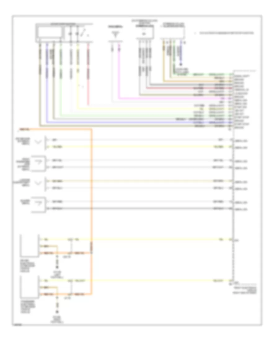
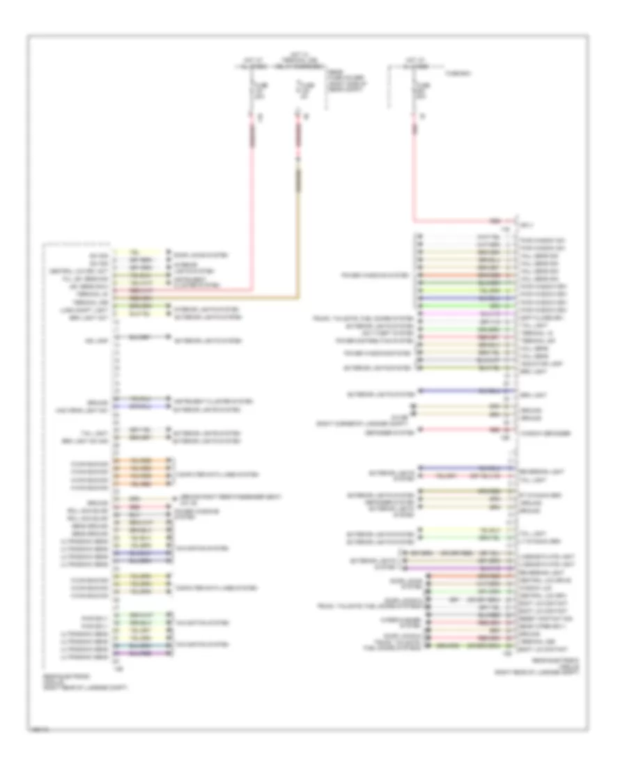
Front Electronic Control Module Wiring Diagram (1 of 3) for BMW ActiveHybrid 3 2014
List of elements for Front Electronic Control Module Wiring Diagram (1 of 3) for BMW ActiveHybrid 3 2014:
- (or pnk)
- 1 to 8 (not used)
- 17 to 26 (not used)
- 35 to 44 (not used)
- Aerial sig
- Air conditioning system
- Ambient light
- Anti-theft & trunk, tailgate, fuel doors systems
- Anti-theft system
- Bus sig
- Bus sig diag
- Computer data lines system
- Courtesy light
- Ctrl valve
- Data line
- Door locks & anti-theft systems
- Dr cont sig
- Eng start sig
- Engine controls system
- Front electronic module (right end of dash)
- Fuse 125a
- Fuse box
- Headlights system
- Hi bem light
- Hi range
- Hi variant
- Horns system
- Hot at all times
- Instrument cluster system
- Inter light
- Interior lights system
- K can bus
- K can2 bus
- K-can2 bus
- Level sens
- Lin bus
- Lin bus sig
- Lo bem light
- Lo range
- Loc lighting
- Lock sig
- Mag clutch
- Pnk
- Pnk/red
- Pt can bus
- Pt can h
- Pt can l
- Red
- Sens sig
- Sig
- Sply
- Starting/charging system
- Sw sig
- Terminal 15n
- Trunk, tailgate, fuel doors system
- Wake up
- Washer pump
- Water valve
- Wind wper
- Wiper
- Wiper/washer system
- Wiper/washer system door locks & trunk, tailgate, fuel doors systems
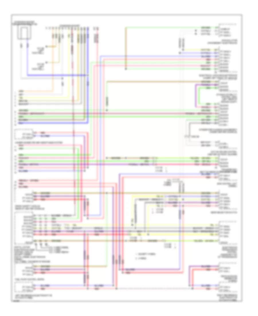
Front Electronic Control Module Wiring Diagram (2 of 3) for BMW ActiveHybrid 3 2014
List of elements for Front Electronic Control Module Wiring Diagram (2 of 3) for BMW ActiveHybrid 3 2014:
- (right footwell) z10 6b
- Act rly
- Air conditioning system
- Anti-theft system
- Auc sens
- Brk sw
- Cen loc drv
- Clutch mod
- Comfort access
- Computer data lines system
- Cruise control & starting/charging systems
- Defogger & memory systems
- Door locks & anti-theft systems
- Door locks & trunk, tailgate, fuel doors systems
- Door locks system
- Drv act
- Exterior lights system
- Fog lights
- Front electronic module (right end of dash)
- Front power distribution box (right rear of engine compt)
- Fuse 40a
- Gear sw
- Ground
- Hall sens sig
- Headlights system
- Hi beam
- Hot at all times
- Hzg lights sw
- Ind lamp
- Instrument cluster system
- Int light
- Int lights
- Interior lights system
- Jet heater
- Led act hzd warn light sw
- Left sig light
- Lev sens
- Light act
- Lin bus
- Lin bus sig
- Lo beam
- Lock drv act
- Mirror act
- Nav conn
- Power windows system
- Press sens
- Pwr slpy
- Pwr sply
- Pwr wind drv
- Red
- Relay act
- Right sig light
- Sens ground
- Sens sig
- Sens sply
- Shutter act
- Side light act
- Sw sig
- Terminal 15 sply
- Terminal 15n
- Terminal 15n relay
- Terminal 30
- Terminal 30b
- Terminal 30b relay
- Terminal 30f
- Trunk, tailgate, fuel doors system
- Ventilation grille
- Washer pump
- Window sw
- Wiper/washer system
- Z10 5b (right footwell)
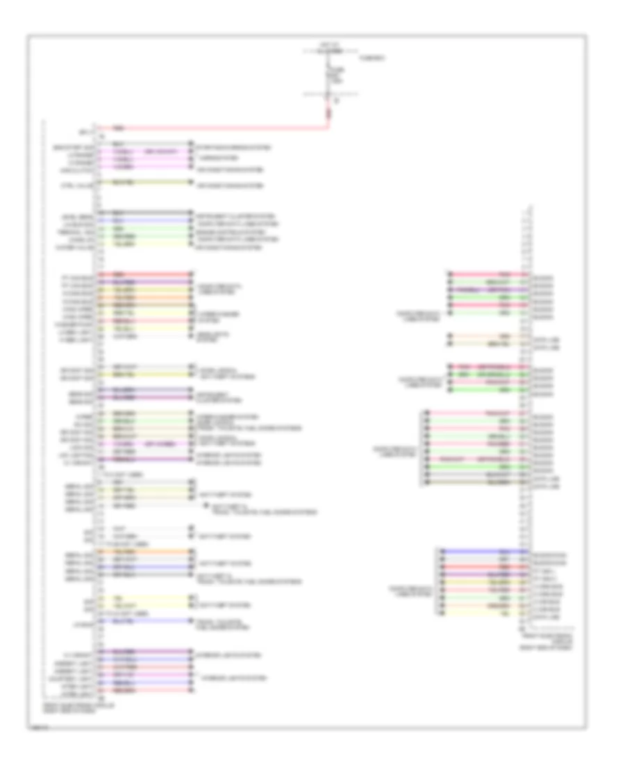
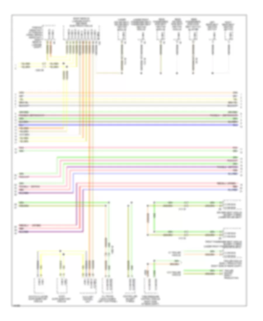
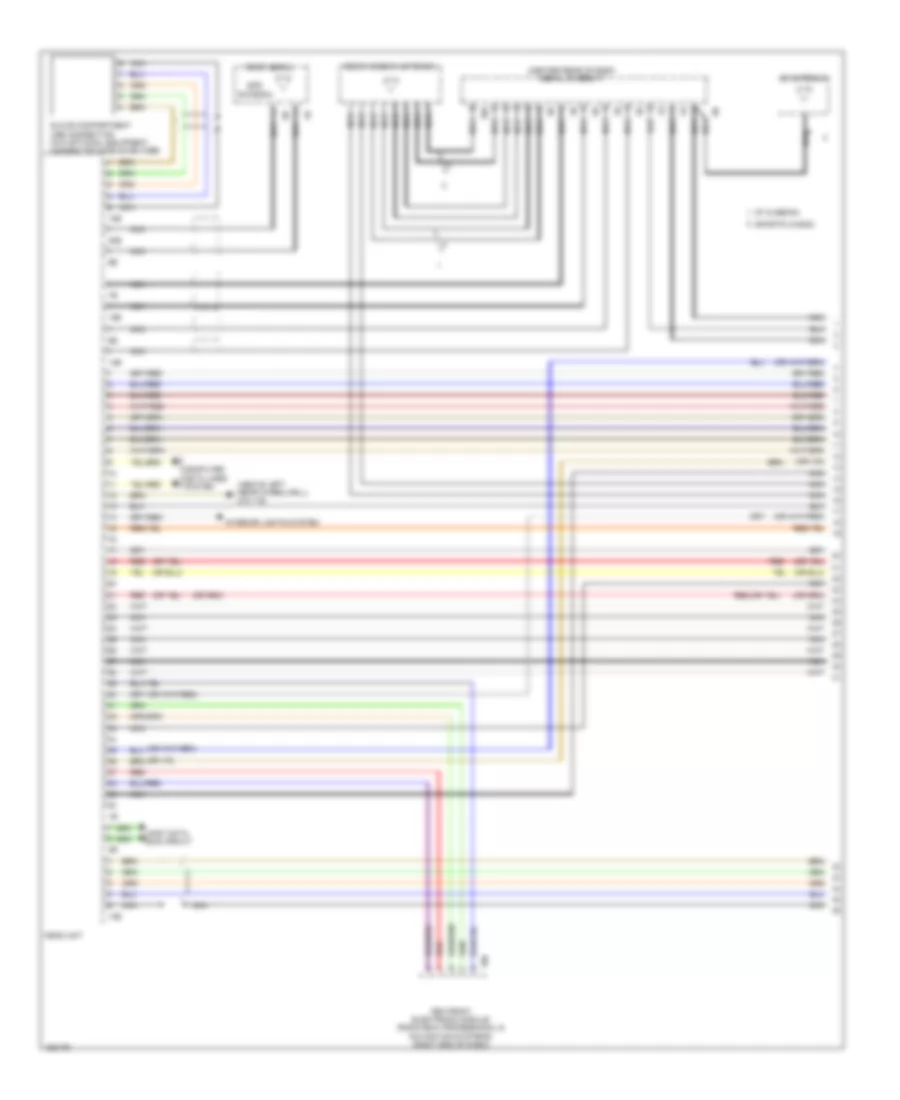
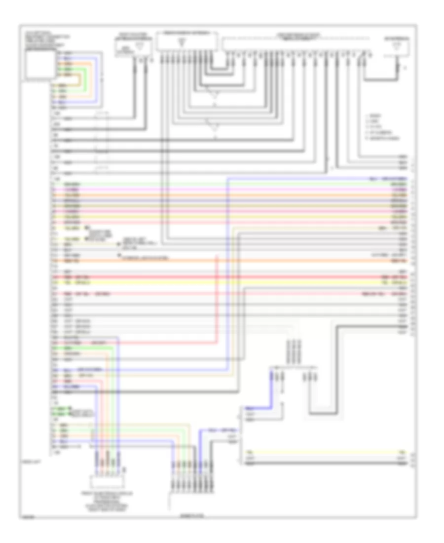
Front Electronic Control Module Wiring Diagram (3 of 3) for BMW ActiveHybrid 3 2014
List of elements for Front Electronic Control Module Wiring Diagram (3 of 3) for BMW ActiveHybrid 3 2014:
- (or red)
- 10b
- Aerial sig
- Air conditioning system
- Anti-theft system
- Arrest button
- Bistable relay
- Computer data lines system
- Data line
- Door locks & interior lights systems
- Door locks & trunk, tailgate, fuel doors systems
- Door locks system
- Exterior lights & interior lights systems
- Exterior lights system
- Front electronic module (right end of dash)
- Ground
- Head up disp
- Horns system
- Instrument cluster system
- Interior lights system
- K can h
- K can l
- K-can2 bus
- Led activation
- Led activation
- Light sw
- Lin bus sig
- Locator light
- Navigation system
- Out side sig
- Position sw
- Pt can h
- Pt can l
- Pwr sply
- Rear fuse holder (right side of rear compt)
- Red
- Sig shift
- Sound systems
- Start sig
- Start stop
- Starting/charging & anti-theft systems
- Terminal 15
- Terminal 15n relay
- Terminal 30
- Terminal 30b relay
- Terminal 30f
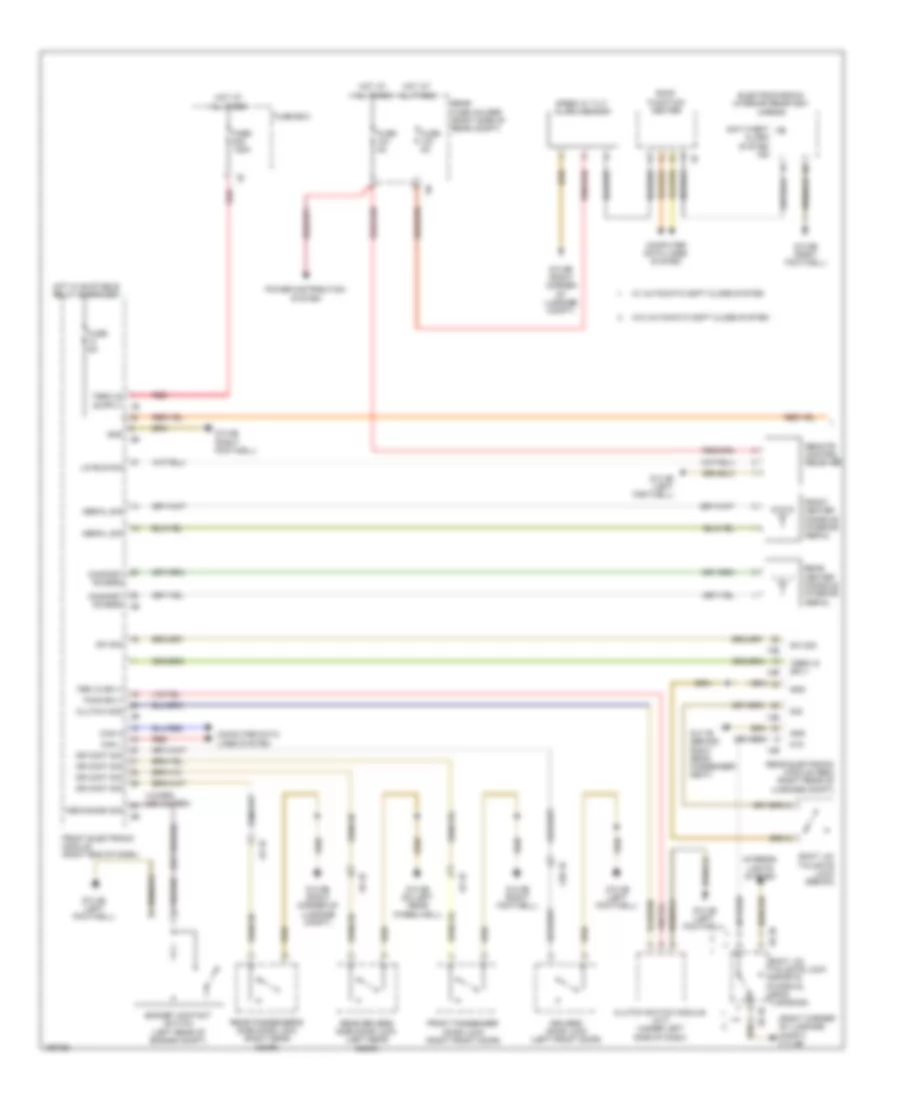
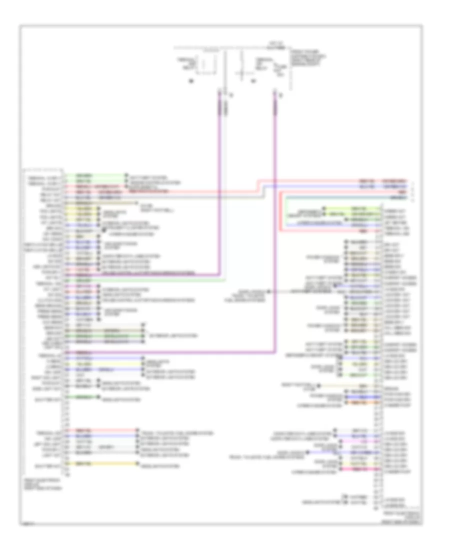
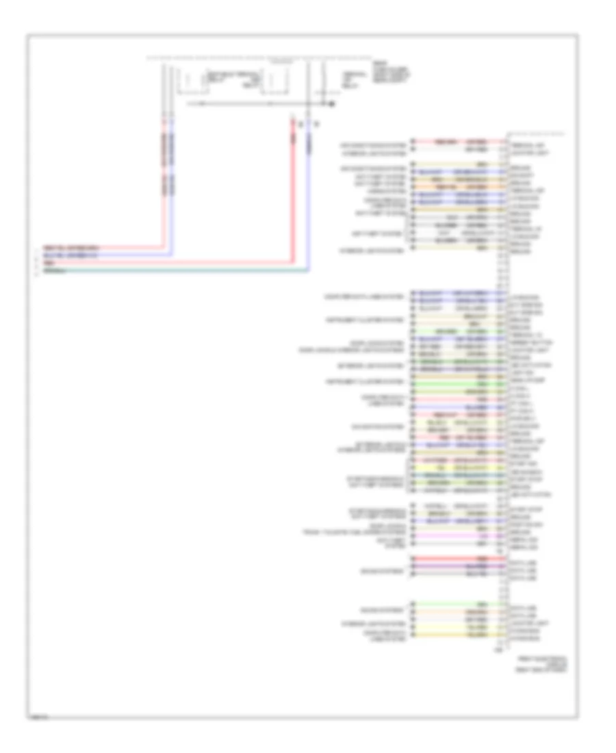
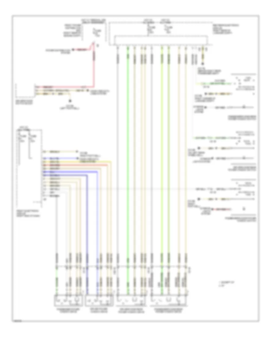
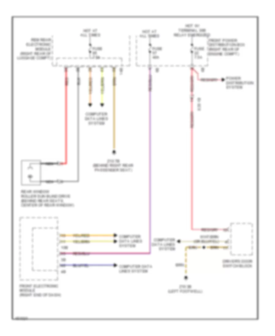
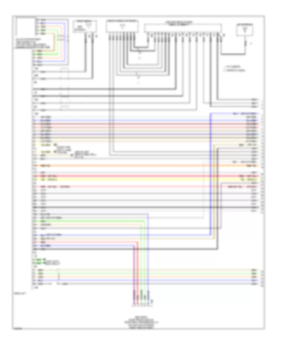
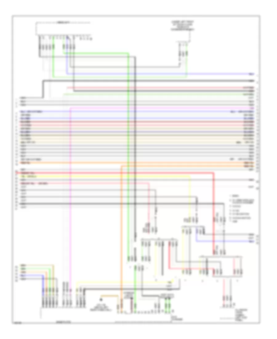
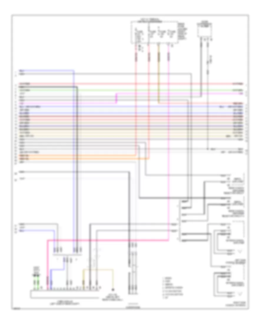
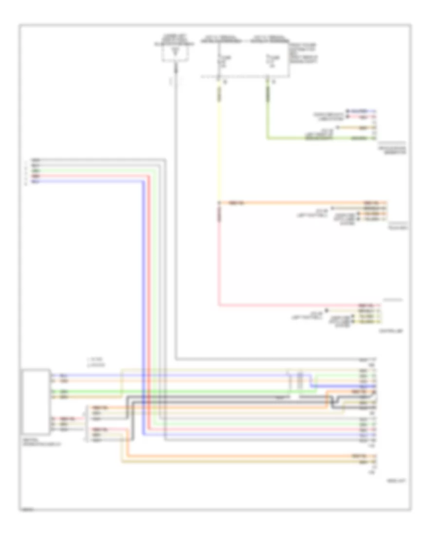
Rear Electronic Control Module Wiring Diagram for BMW ActiveHybrid 3 2014
List of elements for Rear Electronic Control Module Wiring Diagram for BMW ActiveHybrid 3 2014:
- (behind right rear passenger seat) z10 7b
- 11b
- 12b
- 13b
- 14b
- Anti-theft system
- Boot lid contact
- Brk light
- Brk light act
- Brk light sw sig
- Central lck drive
- Central lck drv act
- Central loc driv
- Computer data lines system
- Defogger system
- Door locks & trunk, tailgate, fuel doors systems
- Door locks system
- Exterior lights system
- Ful lev sens sig
- Fuse 20a
- Fuse 50a
- Fuse 5a
- Fuse box
- Ground
- Hall sens
- Hall sens sig
- Haz wrng light sw
- Hot at all times
- Hot w/ terminal 30b relay energized
- Ind lamp
- Indicator lamp
- Instrument cluster system
- Interior lights system
- K-can bus sig
- Lev sens sig 2
- Licence plate light
- Lt dynamic brk
- Lugg compt light
- Navigation system
- Power distribution system
- Power windows system
- Pwr sply
- Pwr window drv
- Pwr window sw
- Rear electronic module (right rear of luggage compt)
- Rear fuse holder (right side of rear compt)
- Rear wiper sply
- Red
- Reset contact sig
- Reversing light
- Roll sun blind
- Rt dynamic brk
- Sens ground
- Soft-close drv
- Sply
- Sw sig
- Tail light
- Terminal 15
- Terminal 30
- Terminal 30b
- Terminal 30f
- Trunk, tailgate, fuel doors system
- Ultrasonic sens
- Window defogger
- Window lck
- Wiper/washer system
- Z10 9b (right corner of luggage compt)
COMPUTER DATA LINES
Computer Data Lines Wiring Diagram (1 of 4) for BMW ActiveHybrid 3 2014
List of elements for Computer Data Lines Wiring Diagram (1 of 4) for BMW ActiveHybrid 3 2014:
- (or pnk)
- (or red)
- 10b
- Ac line
- Active sound design
- Awd
- Blower output stage
- Bus sig
- Bus sig diag
- Can h
- Can l
- Combox (w/ combox) telematic communication box (w/o combox) (w/o combox: under left front 1b of trunk floor) (w/ combox: under left side of luggage compt floor)
- Data line
- Driver's door switch block
- Driver's exterior mirror
- Electronic damper control (right rear of luggage compt) 1b
- Except hybrid
- Fem front electronic module (right end of dash)
- Flex bus sig
- Front passenger exterior mirror
- Fuse 125a
- Fuse 7.5a
- Fuse box
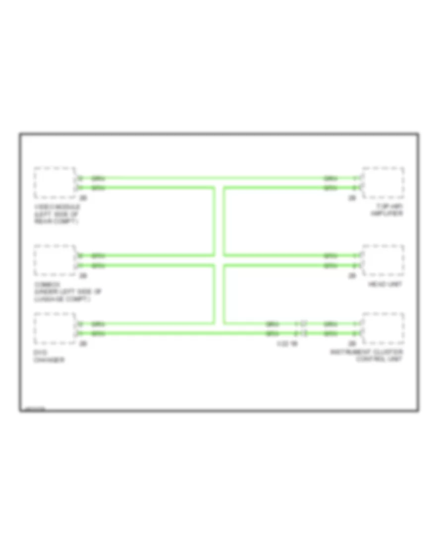
- Head unit
- Heating/air conditioning system (early production) (center of dash, above radio)
- Heating/air conditioning system (late production) (center of dash, above radio) 2b
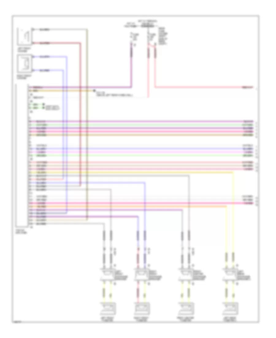
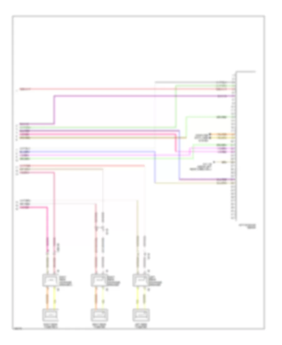
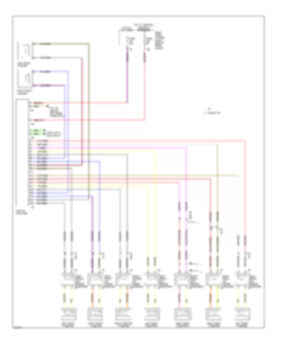
- Hifi amplifier
- Hot at all times
- Hot w/ terminal 30f relay energized
- Hybrid
- Instrument cluster control unit
- K can bus
- K can2 bus
- K can2 h
- K can2 l
- K lin
- K line
- K-can2 bus
- K-lin
- K-lin-1
- Light switch unit
- Lin bus sig
- Pnk
- Pnk/red
- Pt can h
- Pt can l
- Rain/light/ solar/ condensation sensor (solar sensor: top center of dash) (except solar sensor: center of windshield)
- Red
- Rwd
- Sply
- Steering column switch cluster
- W15up
- X20 1b
- X28 1b
- X5 1b
Computer Data Lines Wiring Diagram (2 of 4) for BMW ActiveHybrid 3 2014
List of elements for Computer Data Lines Wiring Diagram (2 of 4) for BMW ActiveHybrid 3 2014:
- (hybrid) controller
- (or pnk)
- (or red)
- (right side of rear compt)
- (under drivers seat) (hybrid) drivers seat module
- (under front passenger's seat) (hybrid) front passenger seat module
- Automatic luggage compartment lid actuation
- Bus sig
- Driver seat belt extender controller
- Electrochromic interior rearview mirror
- Electromechanical power steering (on steering rack)
- Except hybrid & hybrid w/ lane change warning
- Front passenger seat belt extender controller
- Hybrid w/o lane change warning
- K can2 h
- K can2 l
- K-can2 bus
- K-lin
- K-lin-14
- Lane change warning (right corner of rear bumper)
- Left headlight
- Pnk
- Pnk/red
- Red
- Right headlight
- Roof function center
- Touch box
- Trailer module (late production)
- Trailer socket (late production)
- W/ trailer module
- W/o trailer module
- X12 1b
- X14 1b
Computer Data Lines Wiring Diagram (3 of 4) for BMW ActiveHybrid 3 2014
List of elements for Computer Data Lines Wiring Diagram (3 of 4) for BMW ActiveHybrid 3 2014:
- (or pnk)
- (or red)
- (right rear of luggage compt) rem rear electronic module
- (under driver seat) driver seat heating module
- (under front passenger seat) passenger seat heating module
- 14b
- All round vision camera (left kick panel)
- Auxiliary control unit
- Can h
- Can l
- Controller (except hybrid)
- Drivers seat module (except hybrid) (under driver seat)
- Front passenger seat module (except hybrid) (under front passenger's seat)
- Heating module
- K can bus
- K can2 h
- K can2 l
- K-lin-14
- K-lin-6
- Left rear seat heating switch
- Parking assistant (w/ parking maneuvering assistant) (right rear of luggage compt)
- Pnk
- Rear driver's side seat
- Rear passenger's side door
- Rear passenger's side seat
- Red
- Right rear seat heating switch
- Seat switch cluster
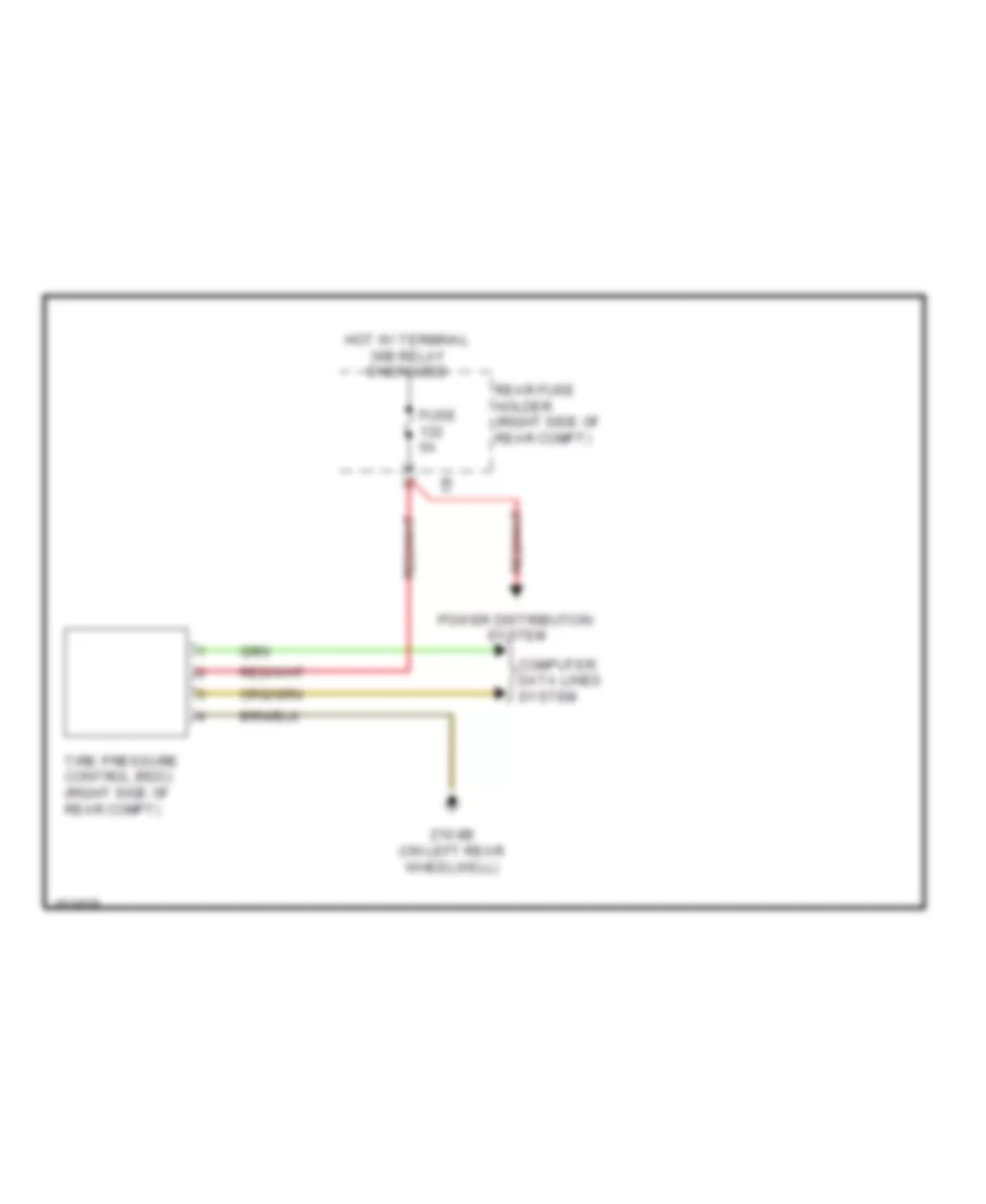
- Tire pressure control module (right side of rear compt)
- Trailer module (early production) (right side of rear compt)
- Trailer socket (early production)
- W/ trailer module
- W/o trailer module
- X12 1b
- X14 1b
- X382 1b
- X382 3b
- X9 1b
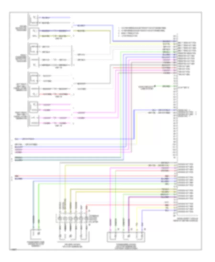
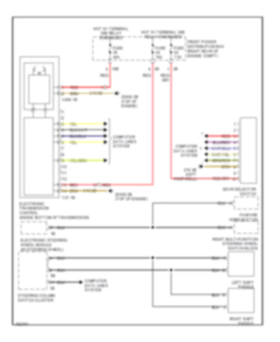
Computer Data Lines Wiring Diagram (4 of 4) for BMW ActiveHybrid 3 2014
List of elements for Computer Data Lines Wiring Diagram (4 of 4) for BMW ActiveHybrid 3 2014:
- (or pnk)
- (or red)
- 15wup
- 2.0l turbo diesel 2.0l turbo 3.0l turbo sedan
- 3.0l turbo hybrid
- Accumulator management electronics
- Active cruise control (center of front bumper)
- Bus sig
- Camera based driver assistance system
- Crash safety module (rear of center console)
- Diagnosis socket
- Diagnosis socket terminating resistor
- Digital motor electronics (dme) control module (except diesel) digital diesel electronics (diesel) (2.0l turbo: top rear of engine)
- Dynamic stability control (dsc) (left rear of engine compt)
- Electrical machine electronics (under left front of vehicle)
- Electronics transmission control (inside bottom of transmission)
- Except hybrid
- Fuel pump control (ekps)
- Gear selector switch
- Hybrid
- Integrated chassis management (under center console)
- Left reversible electromotive automatic reel
- Pnk
- Pt can h
- Pt can l
- Pt can2 h
- Pt can2 l
- Pt can2h
- Pt can2l
- Pt canh
- Pt canl
- Red
- Right reversible electromotive automatic reel
- S can h
- S can l
- Scr control unit (diesel)
- Transfer box (bottom rear of transfer case)
- Vehicle sound generator (hybrid)
- Wake-up
- X13 1b
- X13 2b
- X13 5b
- X13 6b
- X252 2b
- Z10 3b (left footwell)
- Z10 4b (left footwell)
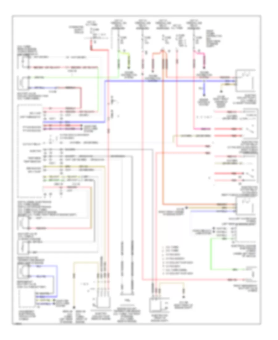
COOLING FAN
Cooling Fan Wiring Diagram for BMW ActiveHybrid 3 2014
List of elements for Cooling Fan Wiring Diagram for BMW ActiveHybrid 3 2014:
- (3.0l turbo: rear of engine) characteristic map thermostat
- 10b
- 2.0l turbo
- 2.0l turbo diesel
- 3.0l turbo
- Auxiliary water pump (hybrid) (left rear of engine compt)
- Bsd bus sig
- Computer data lines system
- Cut-out relay
- Digital diesel electronics (2.0l turbo diesel) digital motor electronics (2.0l turbo & 3.0l turbo) (2.0l turbo: top rear of engine) (except 2.0l turbo: right rear of engine compt)
- Elec fan
- Electric coolant pump (rear of engine)
- Electric coolant pump 2 (3.0l turbo & w/ sport package)
- Electric fan (front of engine compt)
- Electric fan cut-off relay (w/ fan 300w & 400w/600w) (right plenum chamber e-box)
- Electric fan cut-off relay (w/ fan 850w) (right plenum chamber e-box)
- Electrical machine electronics (hybrid) (under left front of vehicle)
- Engine controls system
- Engine coolant temperature sensor (2.0l turbo: top front of engine) (3.0l turbo: rear of engine)
- Front power distribution box (right rear of engine compt)
- Front refrigerant shut-off valve (hybrid)
- Fuse 10a
- Fuse 50a 30a
- Fuse 50a 80a 125a
- Fuse 5a
- Hot at all times
- Hot w/ terminal 15n relay energized
- Hot w/ terminal 30b relay energized
- Management electronics accumulator (hybrid)
- Map thermostat
- Power distribution system
- Pt-can bus sig
- Radiator outlet temperature sensor (right side of engine)
- Red
- Refrigerant shut-off valve (high voltage battery)
- Shut-off valve (3.0l turbo & w/ sport package)
- Shutoff valve coolant expansion tank (2.0l turbo diesel)
- Sply map
- Sply pump
- Temp sens
- Temp sens sig
- W/ coolant pump 200w
- W/ coolant pump 400w
- W/ fan 300w
- W/ fan 300w & 400w/600w
- W/ fan 400/600w
- W/ fan 850w
- X13 1b
- X13-3b
- X2411
- X664 1b
- X664 2b
- X671 1b
- X705 1b
- Z10 15b (right front of engine compt)
- Z10 2b (right front corner of engine compt)
- Z6000 3b (2.0l turbo) (front of engine)
- Z6000 4b (3.0l turbo) (left rear of engine)
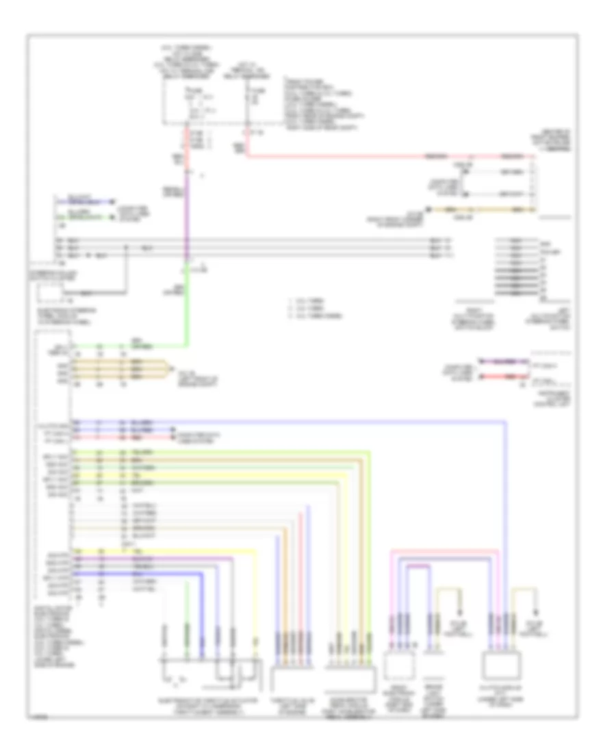
CRUISE CONTROL
Cruise Control Wiring Diagram for BMW ActiveHybrid 3 2014
List of elements for Cruise Control Wiring Diagram for BMW ActiveHybrid 3 2014:
- (2.0l turbo diesel) hot w/ dme relay energized (2.0l turbo & 3.0l turbo) hot w/ terminal 30b relay energized
- (center of front bumper) active cruise control
- 10a
- 2.0l turbo
- 2.0l turbo diesel
- 3.0l turbo
- 30a
- Accelerator pedal module (part accelerator pedal assembly)
- Brake light switch (under left side of dash)
- Clutch module (m/t) (under left side of dash)
- Clutch sig
- Computer data lines system
- Digital motor electronics (2.0l turbo & 3.0l turbo) digital diesel electronics (2.0l turbo diesel) (2.0l turbo & 3.0l turbo: lower left side of engine)
- Electromotive throttle actuator (on right cylinder bank throttle body assembly)
- Electronic steering wheel module (in steering wheel)
- Front electronic module (right end of dash)
- Front power distribution box (2.0l turbo & 3.0l turbo) fuse holder (2.0l turbo diesel) (2.0l turbo & 3.0l turbo: right rear of engine compt) (2.0l turbo diesel: right side of rear compt)
- Fuse
- Fuse 5a
- Gnd
- Gnd acc
- Gnd mtr
- Hot w/ terminal 15n relay energized
- Instrument cluster control unit
- Left multifunction steering wheel switch
- Nca
- Pmw-bfi
- Pt can h
- Pt can l
- Red
- Right multi-function steering wheel switch block
- Sig acc
- Sig mtr
- Sply acc
- Sply mtr
- Sply term 30
- Steering column switch cluster
- Throttle valve (left side of engine)
- X13 4b
- X2411
- X252 2b
- X8582
- Z10 1b (left front of engine compt)
- Z10 2b (right front corner of engine compt)
- Z10 4b (left footwell)
- Z7 1b
- Z7 6b
DEFOGGERS
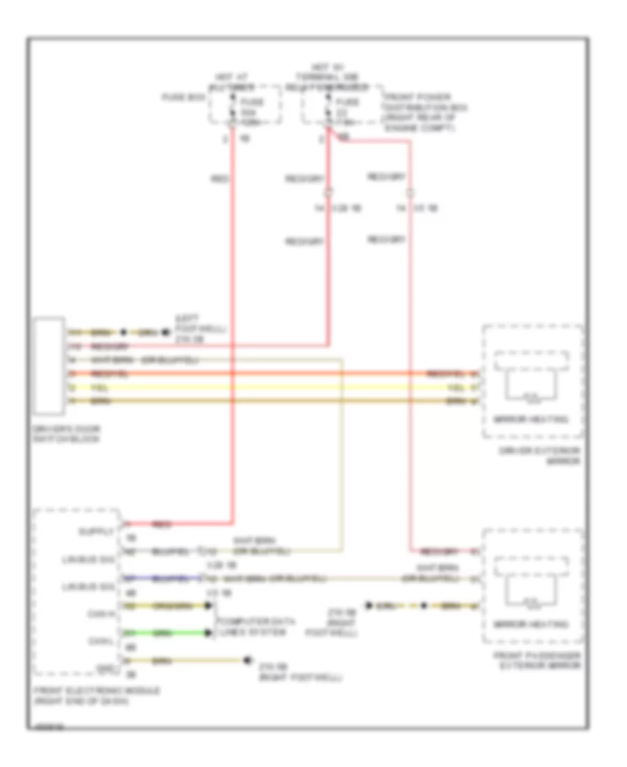
Heated Mirrors Wiring Diagram, with LIN bus Function for BMW ActiveHybrid 3 2014
List of elements for Heated Mirrors Wiring Diagram, with LIN bus Function for BMW ActiveHybrid 3 2014:
- (left footwell) z10 3b
- Can h
- Can l
- Computer data lines system
- Driver exterior mirror
- Driver's door switch block
- Front electronic module (right end of dash)
- Front passenger exterior mirror
- Front power distribution box (right rear of engine compt)
- Fuse 125a
- Fuse 7.5a
- Fuse box
- Gnd
- Hot at all times
- Hot w/ terminal 30b relay energized
- Lin bus sig
- Mirror heating
- Red
- X28 1b
- X5 1b
- Z10 5b (right footwell)
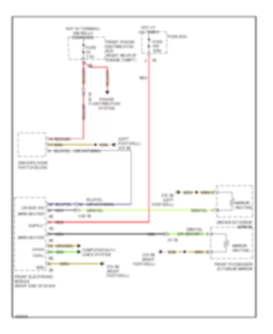
Heated Mirrors Wiring Diagram, without LIN bus Function for BMW ActiveHybrid 3 2014
List of elements for Heated Mirrors Wiring Diagram, without LIN bus Function for BMW ActiveHybrid 3 2014:
- (left footwell) z10 3b
- Can-h
- Can-l
- Computer data lines system
- Driver exterior mirror
- Driver's door switch block
- Front electronic module (right end of dash)
- Front passenger exterior mirror
- Front power distribution box (right rear of engine compt)
- Fuse 125a
- Fuse 7.5a
- Fuse box
- Gnd
- Hot at all times
- Hot w/ terminal 30b relay energized
- Lin bus sig
- Mirr heater
- Mirror heating
- Nca
- Power distribution system
- Red
- X28 1b
- X5 1b
- Z10 3b (left footwell)
- Z10 5b (right footwell)
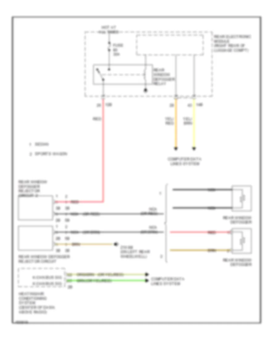
Rear Defogger Wiring Diagram for BMW ActiveHybrid 3 2014
List of elements for Rear Defogger Wiring Diagram for BMW ActiveHybrid 3 2014:
- (or red)
- 12b
- 14b
- Computer data lines system
- Fuse 30a
- Heating/air conditioning system (center of dash, above radio)
- Hot at all times
- K-can bus sig
- Nca
- Nca (or red)
- Rear electronic module (right rear of luggage compt)
- Rear window defogger
- Rear window defogger rejector circuit
- Rear window defogger rejector circuit 2
- Rear window defogger relay
- Red
- Sedan
- Sports wagon
- Z10 8b (on left rear wheelwell)
ELECTRONIC POWER STEERING
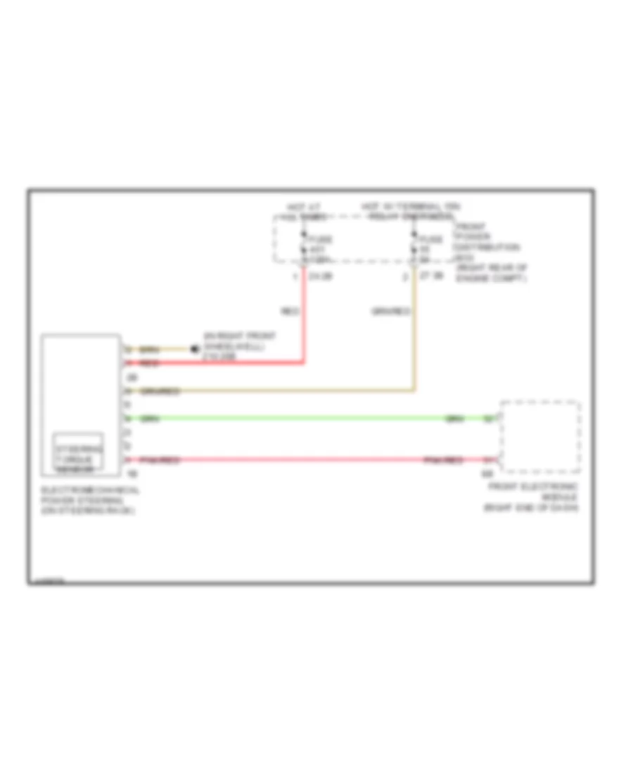
Electronic Power Steering Wiring Diagram for BMW ActiveHybrid 3 2014
List of elements for Electronic Power Steering Wiring Diagram for BMW ActiveHybrid 3 2014:
- (in right front wheelwell) z10 20b
- Electromechanical power steering (on steering rack)
- Front electronic module (right end of dash)
- Front power distribution box (right rear of engine compt)
- Fuse 125a
- Fuse 5a
- Hot at all times
- Hot w/ terminal 15n relay energized
- Pnk/red
- Red
- Steering torque sensor
- Z4 2b
- Z7 3b
ELECTRONIC SUSPENSION
Air Suspension Wiring Diagram for BMW ActiveHybrid 3 2014
List of elements for Air Suspension Wiring Diagram for BMW ActiveHybrid 3 2014:
- (rear of center console) crash safety module
- (right end of dash) front electronic module
- Air bag sens
- Center console operating unit
- Computer data lines system
- Drv dyn ctrl sw sig
- Dtc btn sig
- Dynamic stability control (dsc) (left rear of engine compt)
- Flexray bus sig
- Front power distribution box (right rear of engine compt)
- Function lighting
- Fuse 25 5a
- Ground
- Hot w/ terminal 30b relay energized
- If equipped
- Integrated chassis management (under center console)
- Left front level sensor
- Left rear level sensor
- Lf level sens sig
- Lf level sens sply
- Lr level sens sply
- Parking aid ctrl sig
- Power distribution system
- Sens ground
- Wake up sig, term 15
- Wake-up sig
- Z10 10b (front of center console)
Dynamic Drive Suspension Wiring Diagram for BMW ActiveHybrid 3 2014
List of elements for Dynamic Drive Suspension Wiring Diagram for BMW ActiveHybrid 3 2014:
- 11b
- Activation
- Electronic damper control (right rear of luggage compt)
- Flexray bus sig
- Front electronic module (right end of dash)
- Fuse 20a
- Fuse 5a
- Gnd
- Hot at all times
- Hot w/ terminal 15n relay energized
- Left front coil valve
- Left front vertical-acceleration sensor
- Left rear coil valve
- Lf vertical 5v
- Lf vertical gnd
- Lf vertical sig
- Pnk
- Power distribution system
- Rear fuse holder (right side of rear compt)
- Red
- Rf vertical 5v
- Rf vertical sig
- Right front coil valve
- Right front vertical-acceleration sensor
- Right rear coil valve
- Terminal 15
- Terminal 30
- X0172
- X0173
- X044
- X045
- X046
- X047
- Z10 9b (right corner of luggage compt)
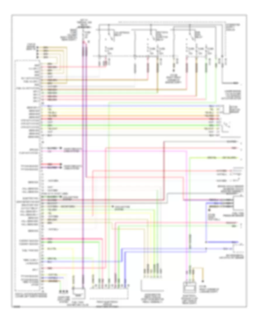
ENGINE PERFORMANCE
3.0L TURBO HYBRID
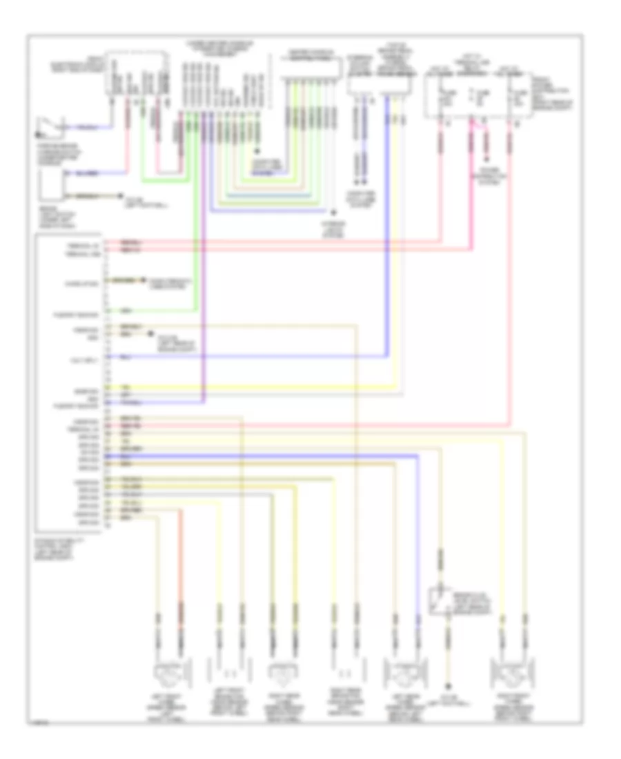
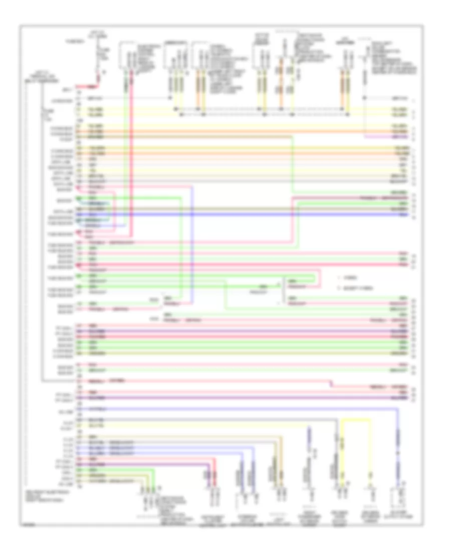
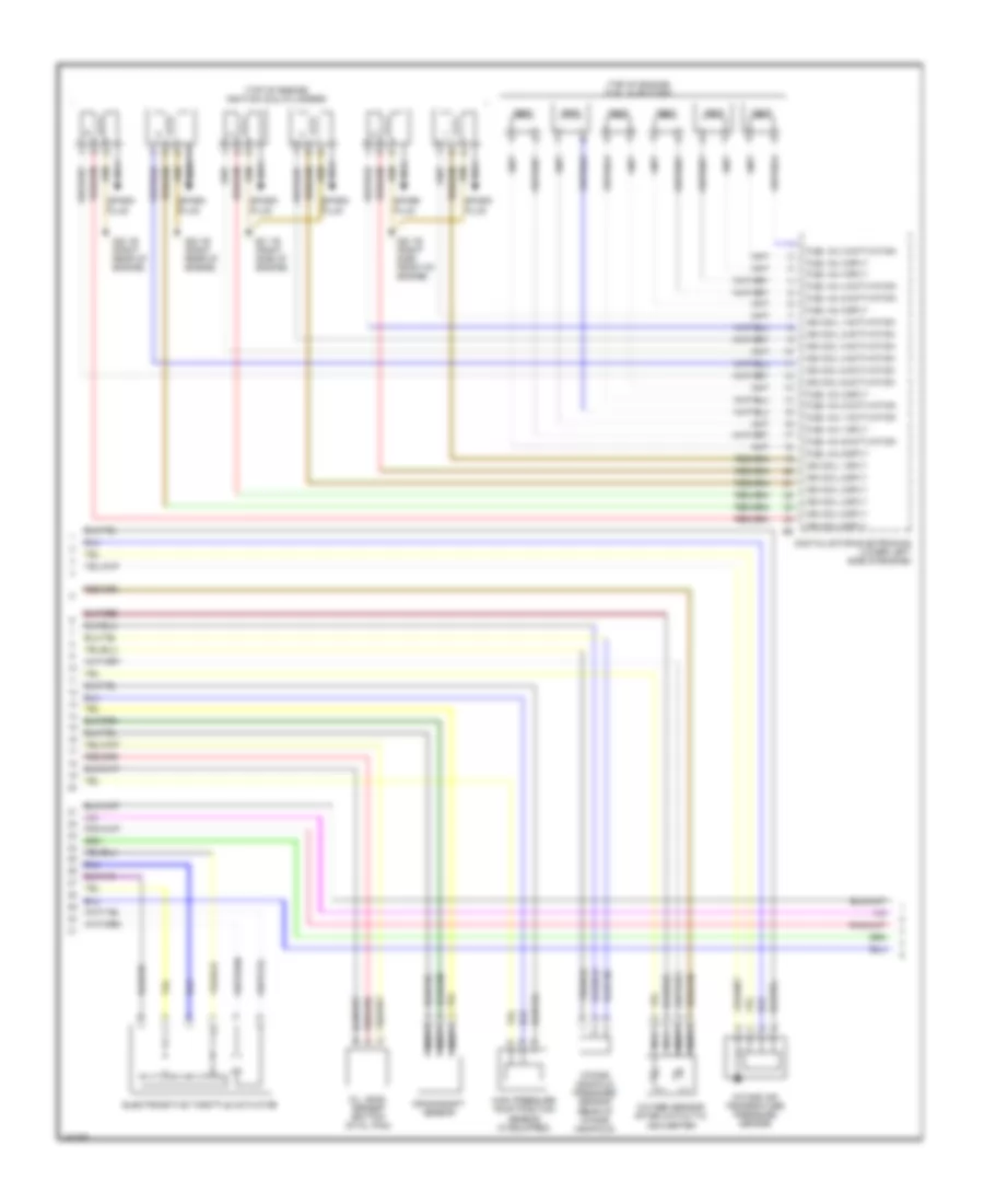
3.0L Turbo Hybrid, Engine Performance Wiring Diagram (1 of 8) for BMW ActiveHybrid 3 2014
List of elements for 3.0L Turbo Hybrid, Engine Performance Wiring Diagram (1 of 8) for BMW ActiveHybrid 3 2014:
- (pins 16 to 19 not used)
- (right corner of luggage compt)
- (top of engine) z6000 1b
- (under engine valve cover) valvetronic actuator motor
- Accelerator pedal module (part accelerator pedal assembly)
- Brake vacuum sensor (on brake vacuum booster assembly)
- Computer data lines system
- Cooling fans system
- Cut-out relay
- Digital motor electronics (lower left side of engine)
- Dme main relay
- Electric fan
- Electrical exhaust flap (left side of rear compt)
- Eng start sig
- Environmental air catalyst sensor
- Flap activation
- Flexray bus sig
- Front electronic module (right end of dash)
- Fuel inj activation
- Fuel inj sply
- Fuel tank non return valve
- Fuel tank pressure sensor
- Fuel tank sig
- Fuse 15a
- Fuse 20a
- Fuse 40a
- Fuse 5a
- Gnd
- Hall sens gnd
- Hall sens sig
- Hall sens sply
- Hot w/ terminal 30b relay energized
- Ignition & fuel injection relay
- Leak detection sig
- Lin bus sig
- Motor position sensor
- Mtr activation
- Nca
- Pnk
- Pt-can bus sig
- Pt-can bus sig term 15 wake up sig
- Rear fuse holder (right side of rear compt)
- Red
- Rly activation
- Sens gnd
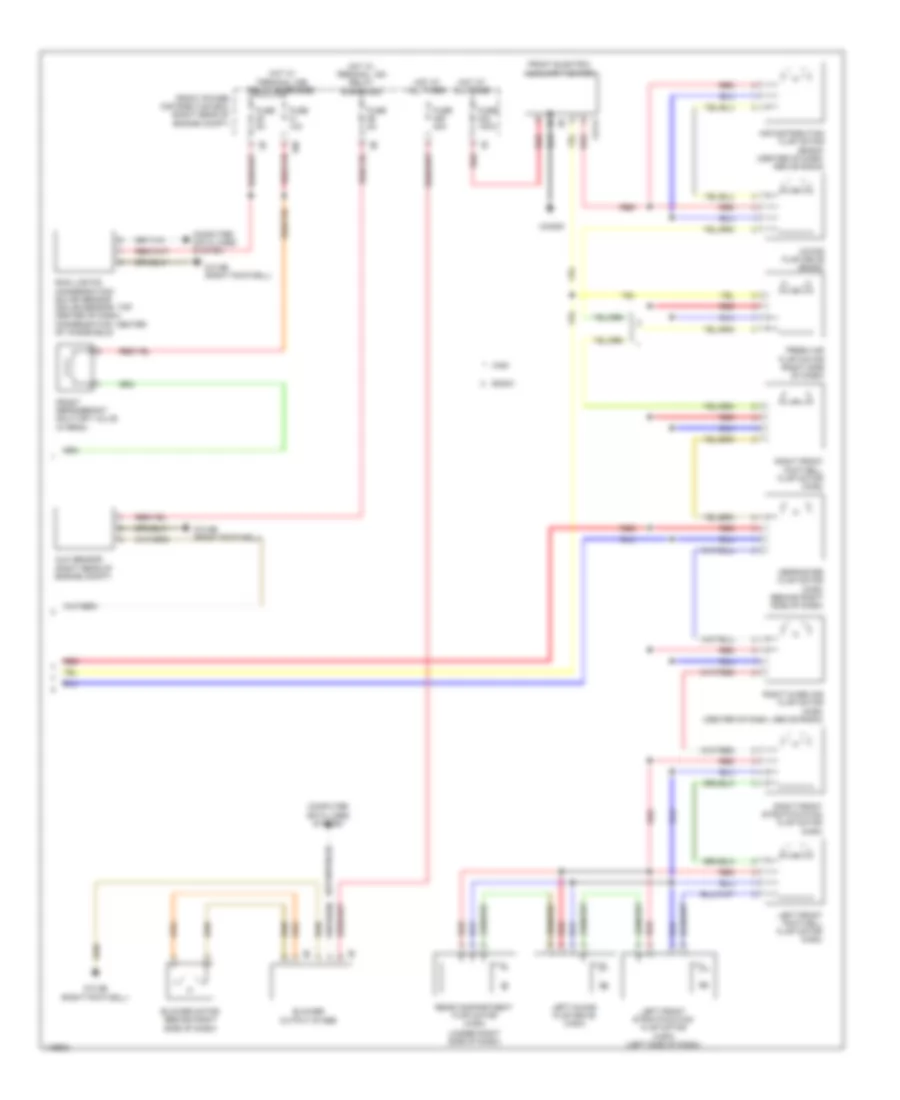
- Sens sig
- Sens sply
- Spd sig
- Sply
- Term 15 sply
- Valvetronic relay
- Vlv sply
- Z10 2b (right front corner of engine compt)
- Z10 6b (right footwell)
- Z10 9b
- Z11 1b
- Z11 3b
- Z11 4b
- Z8 3b
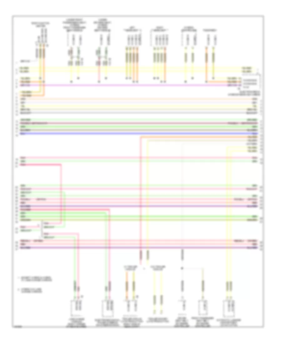
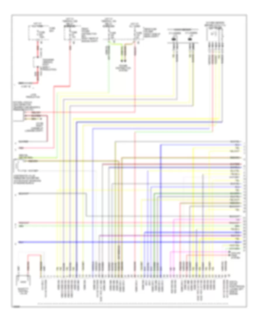
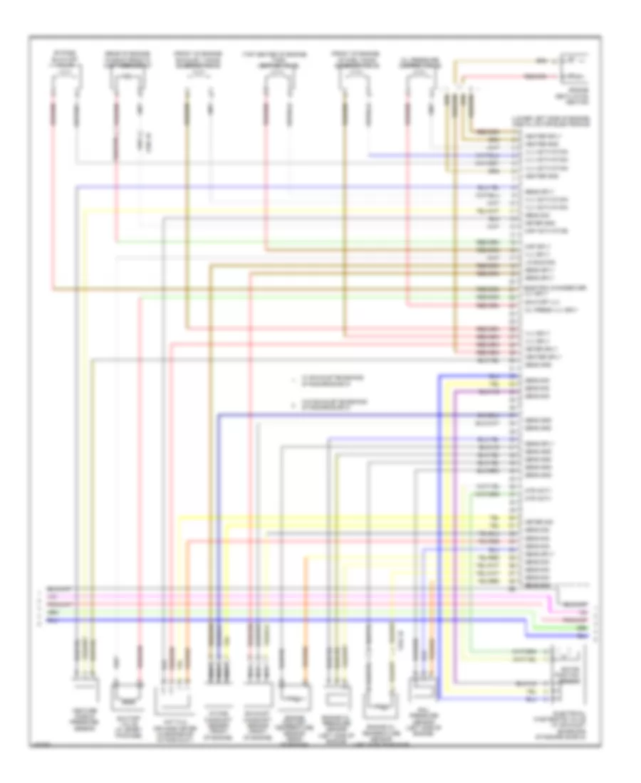
3.0L Turbo Hybrid, Engine Performance Wiring Diagram (2 of 8) for BMW ActiveHybrid 3 2014
List of elements for 3.0L Turbo Hybrid, Engine Performance Wiring Diagram (2 of 8) for BMW ActiveHybrid 3 2014:
- Act activation
- Bsd bus sig
- Cool pmp
- Cooling fans system
- Cylinders 1-3
- Cylinders 4-6
- Digital motor electronics (lower left side of engine)
- Elec trtl act gnd
- Elec trtl act sig
- Front power distribution box (right rear of engine compt)
- Fuse 10a
- Fuse 125a
- Fuse 15a
- Fuse 5a
- Fuse box
- Hot at all times
- Hot w/ terminal 15n relay energized
- Hot w/ terminal 30b relay energized
- Knock sens sig
- Knock sensor
- Late production
- Natural vacuum leak detection temperature sensor & pressure switch
- Nca
- Oxygen sensor before catalytic converter
- Power distribution system
- Quantity control valve
- Rear fuse holder (right side of rear compt)
- Red
- Sens gnd
- Sens sig
- Sens sply
- Sply
- Transfer terminal point (early production)
- Vlv activation
- Vlv sply
- Wastegate valve pressure converter (w/o exhaust emissions standard euro 6)
- X1397 1b
- X541 1b
- X541 2b
- Z10 9b (right corner of luggage compt)
3.0L Turbo Hybrid, Engine Performance Wiring Diagram (3 of 8) for BMW ActiveHybrid 3 2014
List of elements for 3.0L Turbo Hybrid, Engine Performance Wiring Diagram (3 of 8) for BMW ActiveHybrid 3 2014:
- (top of engine) fuel injectors
- (top of engine) ignition coil cylinders
- Crankshaft sensor
- Digital motor electronics (lower left side of engine)
- Electromotive throttle actuator
- Fuel inj 1 activation
- Fuel inj 1 sply
- Fuel inj 2 activation
- Fuel inj 2 sply
- Fuel inj 3 activation
- Fuel inj 3 sply
- Fuel inj 4 activation
- Fuel inj 4 sply
- Fuel inj 5 activation
- Fuel inj 5 sply
- Fuel inj 6 activation
- Fuel inj 6 sply
- High pressure pump position sensor (if equipped)
- Ign coil 1 activation
- Ign coil 1 sply
- Ign coil 2 activation
- Ign coil 2 sply
- Ign coil 3 activation
- Ign coil 3 sply
- Ign coil 4 activation
- Ign coil 4 sply
- Ign coil 5 activation
- Ign coil 5 sply
- Ign coil 6 activation
- Ign coil 6 sply
- Intake air temperature pressure sensor
- Intake manifold pressure sensor (rear of intake manifold)
- Nca
- Oil level sensor (bottom of oil pan)
- Oxygen sensor after catalytic converter
- Spark plug
- Z20 1b (right side front of engine)
- Z21 1b (right side of engine)
- Z22 1b (right rear of engine)
3.0L Turbo Hybrid, Engine Performance Wiring Diagram (4 of 8) for BMW ActiveHybrid 3 2014
List of elements for 3.0L Turbo Hybrid, Engine Performance Wiring Diagram (4 of 8) for BMW ActiveHybrid 3 2014:
- (front of engine)
- (lower left side of engine) digital motor electronics
- (rear of engine) characteristic map thermostat
- (top center of engine)
- Bypass blow-off valve
- Electric changeover vlv sply
- Electrical wastegate valve (w/ exhaust emissions standard euro 6)
- Engine coolant temperature sensor (rear of engine)
- Engine oil pressure sensor (left side of engine)
- Engine oil temperature sensor (left side of engine)
- Engine ventilation heating
- Exhaust camshaft sensor (front of engine)
- Exhaust vanos solenoid valve
- Heater gnd
- Heater sply
- Hot film air mass meter (in engine air intake duct)
- Intake camshaft sensor (front of engine)
- Intake vanos solenoid valve
- Lin bus sig
- Map activation
- Map sply
- Meter gnd
- Meter sig
- Meter sply
- Mtr actv
- Nca
- Oil press vlv sply
- Oil pressure control valve
- Rail pressure sensor (left side of engine)
- Rotor position sensor
- Sens gnd
- Sens sig
- Sens sply
- Shutoff valve (w/ sport package)
- Shutoff vlv
- Tank venting valve
- Venture nozzle pressure sensor
- Vlv activation
- Vlv sply
- W/ exhaust emissions standard euro 6
- W/o exhaust emissions standard euro 6
- X704 1b
- X705 1b
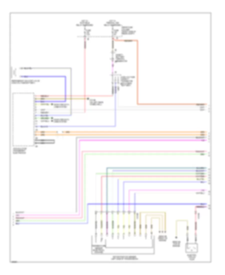
3.0L Turbo Hybrid, Engine Performance Wiring Diagram (5 of 8) for BMW ActiveHybrid 3 2014
List of elements for 3.0L Turbo Hybrid, Engine Performance Wiring Diagram (5 of 8) for BMW ActiveHybrid 3 2014:
- Accumulator management electronics
- Computer data lines system
- Electric vacuum pump
- Fuse 5a
- Fuse 7.5a
- High voltage safety connector (on hybrid 1b battery)
- Hot w/ bi-stable relay energized
- Hot w/ terminal 30b relay energized
- Nca
- Rear fuse holder (right side of rear compt)
- Refrigerant shutoff valve (high-voltage battery)
- Rotor position sensor (left side of transmission)
- Safety battery terminal generator 2b
- Temperature sensor (electrical machine)
- X13 8b
- X13 9b
- Z10 8b (on left rear wheelwell)
- Z6000 2b (top of engine)
- Z6000 3b (front of engine)
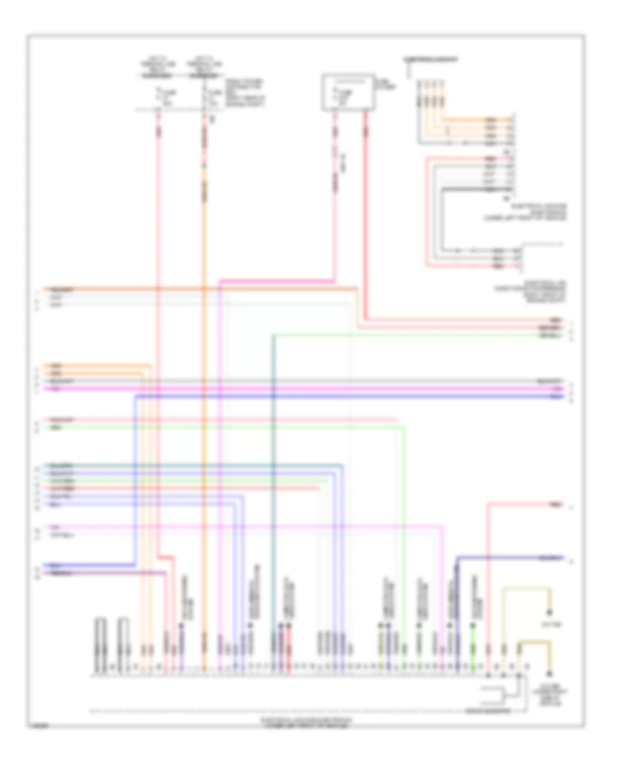
3.0L Turbo Hybrid, Engine Performance Wiring Diagram (6 of 8) for BMW ActiveHybrid 3 2014
List of elements for 3.0L Turbo Hybrid, Engine Performance Wiring Diagram (6 of 8) for BMW ActiveHybrid 3 2014:
- 10b
- Air conditioning system
- Computer data lines system
- Dc/dc generter
- Electrical air conditioning compressor (right front of engine compt)
- Electrical machine
- Electrical machine electronics (under left front of vehicle)
- Front power distribution box (right rear of engine compt)
- Fuse 10a
- Fuse 40a
- Fuse 5a
- Fuse holder
- Hot w/ terminal 30b relay energized
- Nca
- Red
- System air conditioning
- X601 1b
- Z10 29b (under right side of vehicle)
- Z10 70b
3.0L Turbo Hybrid, Engine Performance Wiring Diagram (7 of 8) for BMW ActiveHybrid 3 2014
List of elements for 3.0L Turbo Hybrid, Engine Performance Wiring Diagram (7 of 8) for BMW ActiveHybrid 3 2014:
- (right front of engine)
- 11b
- Auxiliary battery
- Battery
- Capacitor box
- Cut-off relay
- Front power distribution box (right rear of engine compt)
- Fuse 100a
- Fuse 20a
- Fuse 40a
- Fuse 5a
- Fuse box
- Fuse box 2
- Hot w/ terminal 30b relay energized
- Intelligent battery sensor 2
- Nca
- Rear fuse holder (right side of rear compt)
- Red
- Safety battery terminal generator
- Safety battery terminal starter unit generator
- Starter motor generator
- Transfer terminal point 3
- X13 1b
- X601 1b
- X671 3b
- Z10 26b
- Z6000 2b (top of engine)
3.0L Turbo Hybrid, Engine Performance Wiring Diagram (8 of 8) for BMW ActiveHybrid 3 2014
List of elements for 3.0L Turbo Hybrid, Engine Performance Wiring Diagram (8 of 8) for BMW ActiveHybrid 3 2014:
- (under right rear seat) (w/ ethanol sensor) electric fuel pump
- Computer data lines system
- Early production
- Electric fuel pump (w/o ethanol sensor) (under right rear seat)
- Fuel pump control (ekps)
- Jump start terminal point (right side of engine compt)
- Late production
- Nca
- Positive battery connection point
- Red
- Red 1b
- Reverse polarity protection (right front corner of engine compt)
- Starter
- Transfer terminal point
- Z10 7b (behind right rear passenger seat)
EXTERIOR LIGHTS
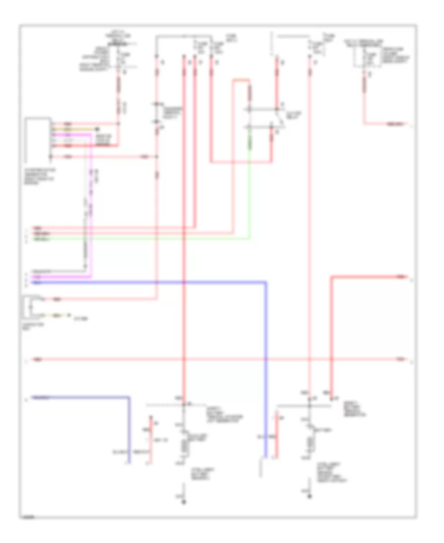
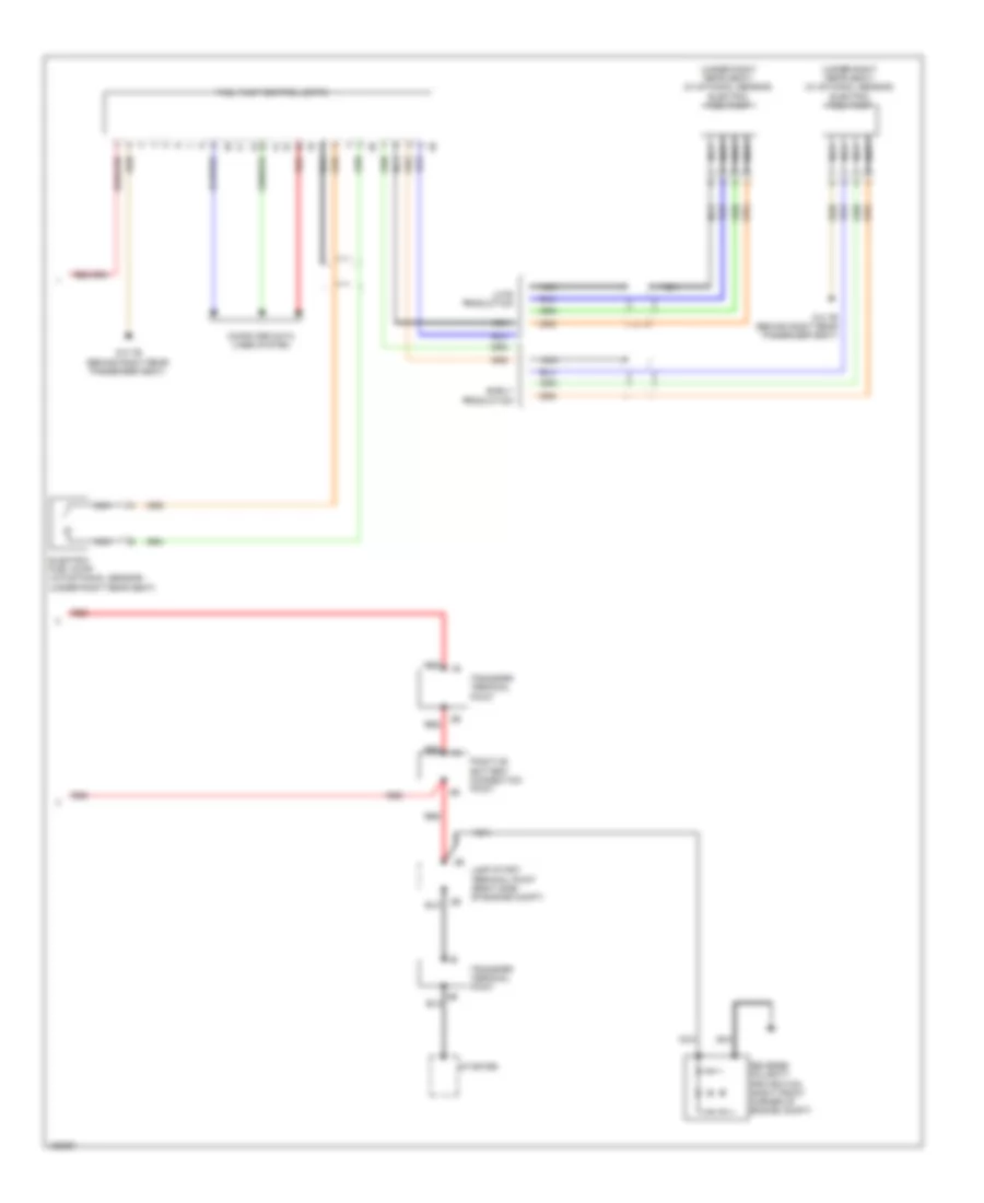
Backup Lamps Wiring Diagram for BMW ActiveHybrid 3 2014
List of elements for Backup Lamps Wiring Diagram for BMW ActiveHybrid 3 2014:
- (right footwell) z10 5b
- 13b
- 14b
- 2.ol & 3.0l turbo
- 2.ol turbo
- 2.ol turbo diesel
- 3.ol turbo
- Can bus sig
- Computer data lines system
- Electronic transmission control (except hybrid) automatic transmission (hybrid) (except hybrid: inside bottom of transmission)
- Except gt
- Front electronic module (right end of dash)
- Front power distribution box (right rear of engine compt)
- Fuse 40a
- Gear select switch
- Gnd
- Hot at all times
- Left inner taillight
- Lt rev sw
- Rear electronic module (right rear of luggage compt)
- Red
- Rev gear sw
- Reverse
- Reversing gear switch (m/t)
- Right inner taillight
- Rt rev lt
- Term 30
- X13 1b
- X13 4b
- Z10 1b (left front of engine compt)
- Z10 7b (behind right rear passenger seat)
- Z6000 1b (top of engine)
- Z6000 4b (left rear of engine)
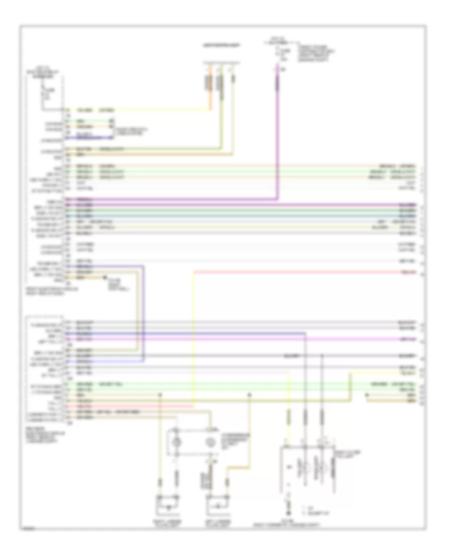
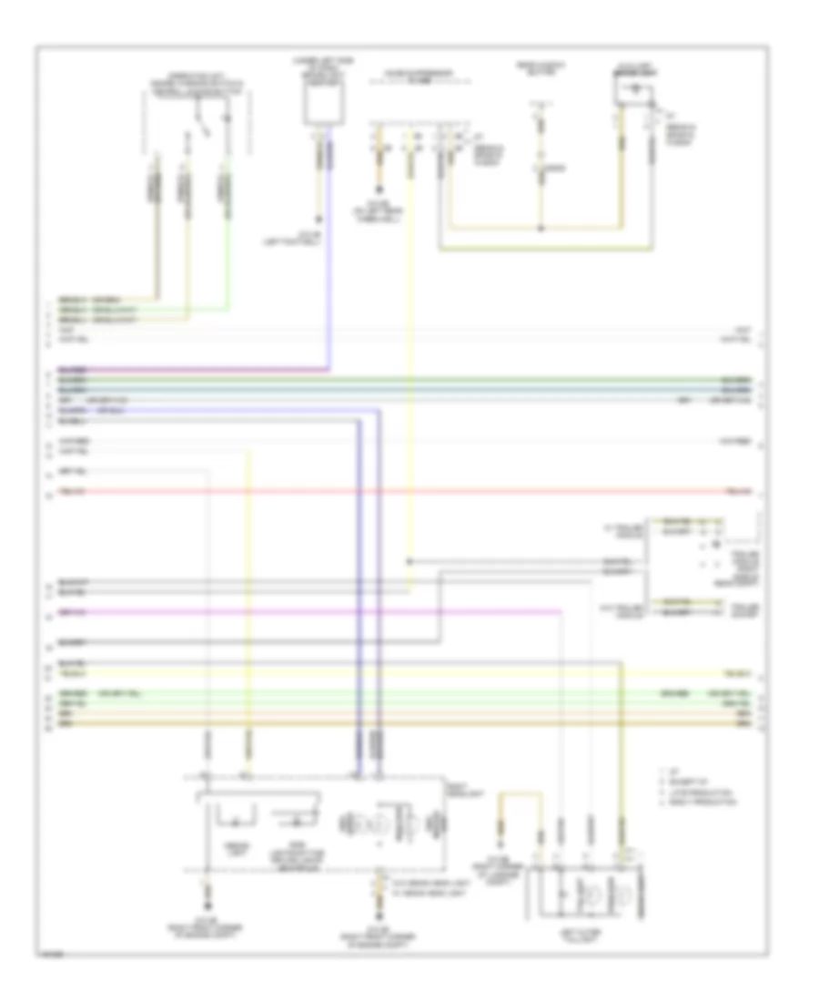
Exterior Lamps Wiring Diagram (1 of 3) for BMW ActiveHybrid 3 2014
List of elements for Exterior Lamps Wiring Diagram (1 of 3) for BMW ActiveHybrid 3 2014:
- (or red)
- 12b
- 13b
- 14b
- Aux brk
- Brake light
- Brk lt
- Brk lt sw sig
- Can bus
- Computer data lines system
- Direction
- Except gt
- Flashing ind lp
- Front electronic module (right end of dash)
- Front power distribution box (right rear of engine compt)
- Fuse 40a
- Fuse 5a
- Gnd
- Hot at all times
- Hot w/ bi-stable relay energized
- Hzd warn lt sw
- Interference suppressor filter 2 (gt)
- Led act
- Left license plate light
- Left tail lt
- License plate lt
- Light switch unit
- Lin bus sig
- Lt dynamic brk
- Power sply
- Pwr sply
- Rem rear electronic module (right rear of luggage compt)
- Right license plate light
- Right outer taillight
- Rt dynamic brk
- Rt tail lt
- Side lts act
- St stp button
- Tail light
- Tail lt
- Term 30
- Z10 5b (right footwell)
- Z10 9b (right corner of luggage compt)
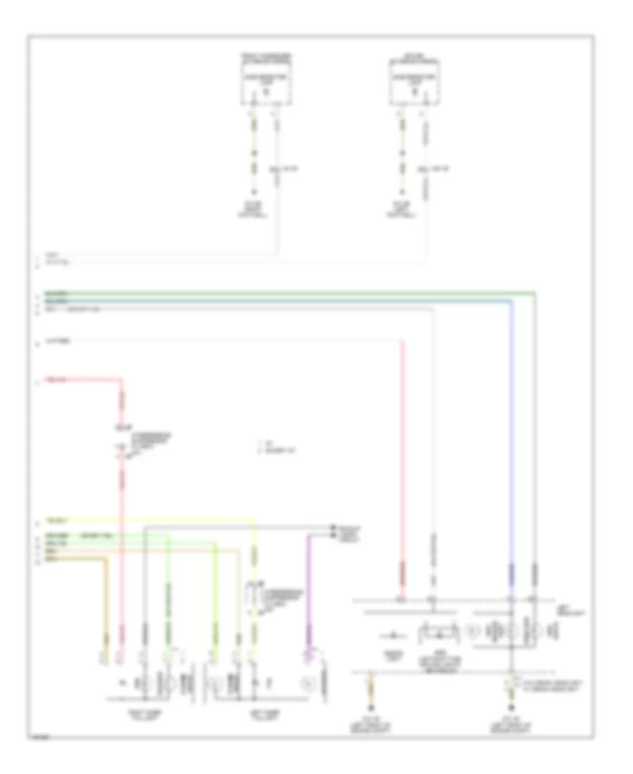
Exterior Lamps Wiring Diagram (2 of 3) for BMW ActiveHybrid 3 2014
List of elements for Exterior Lamps Wiring Diagram (2 of 3) for BMW ActiveHybrid 3 2014:
- (under left side of dash) brake light switch
- Auxiliary brake light
- Brake light
- Design light
- Direction
- Early production
- Except gt
- Late production
- Left outer taillight
- Lights side
- Noise suppressor filter
- Operating unit, hazard warning switch & central locking button
- Rear window button
- Right headlight
- Sedan & sports wagon
- Side lights/daytime driving lights led module
- Side marker light
- Tail light
- Trailer module (right side of rear compt)
- Trailer socket
- W/ trailer module
- W/ xenon head light
- W/o trailer module
- W/o xenon head light
- X25828
- Z10 2b (right front corner of engine compt)
- Z10 4b (left footwell)
- Z10 8b (on left rear wheelwell)
- Z10 9b (right corner of luggage compt)
Exterior Lamps Wiring Diagram (3 of 3) for BMW ActiveHybrid 3 2014
List of elements for Exterior Lamps Wiring Diagram (3 of 3) for BMW ActiveHybrid 3 2014:
- Backup lamps circuit
- Brake dynamic
- Design light
- Direction
- Driver exterior mirror
- Dynamic brake
- Except gt
- Front passenger exterior mirror
- Interference suppressor filter 2 (gt)
- Left headlight
- Left inner taillight
- Reverse
- Right inner taillight
- Side lights
- Side lights/daytime driving lights led module
- Side marker light
- Side repeater lamp
- Tail
- W/ xenon headlight
- W/o xenon headlight
- X28 1b
- X5 1b
- Z10 1b (left front of engine compt)
- Z10 3b (left footwell)
- Z10 5b (right footwell)
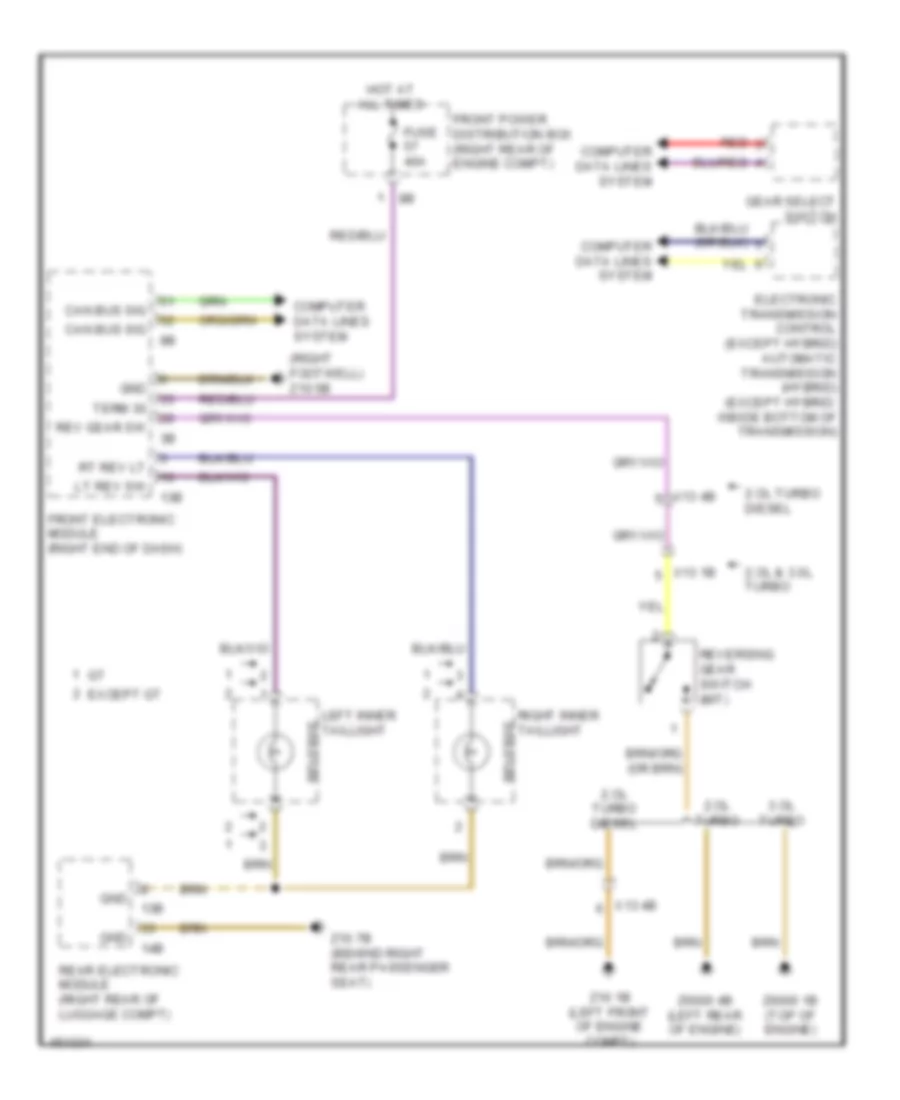
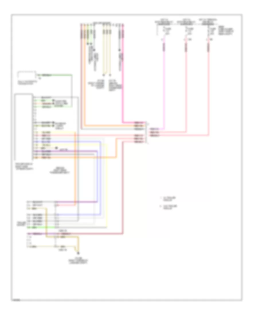
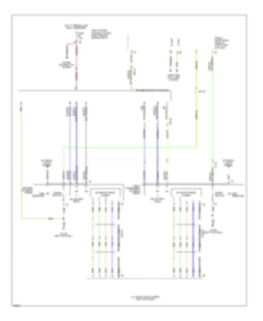
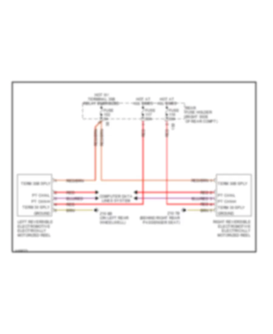
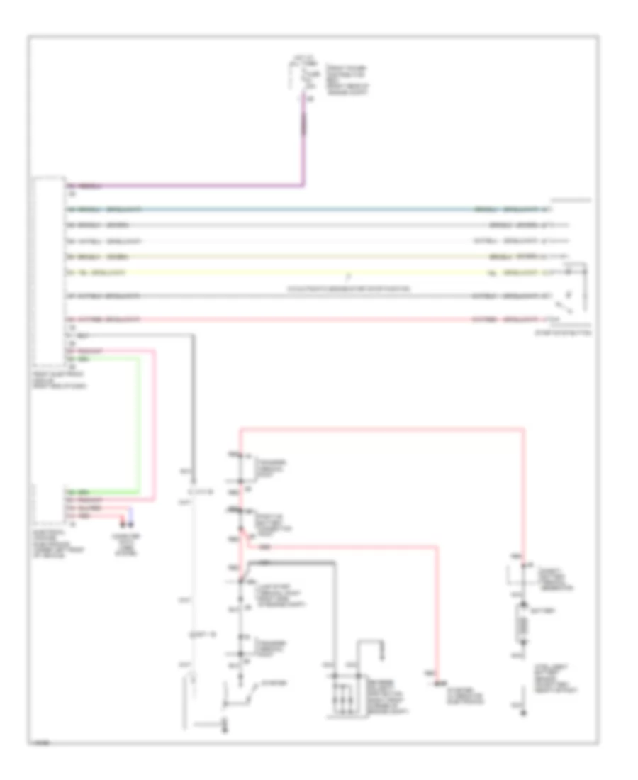
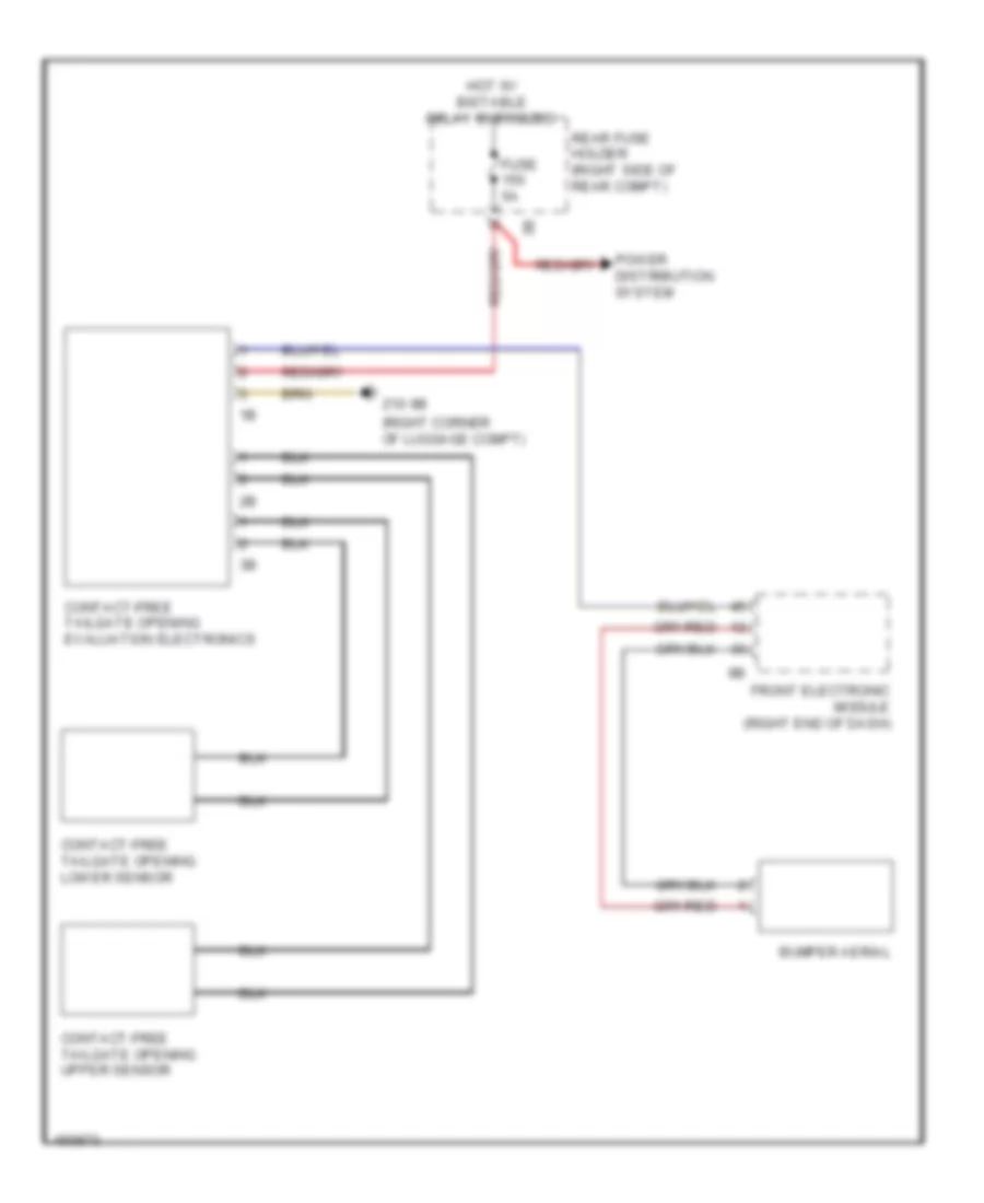
Trailer Tow Wiring Diagram, Early Production for BMW ActiveHybrid 3 2014
List of elements for Trailer Tow Wiring Diagram, Early Production for BMW ActiveHybrid 3 2014:
- (behind right rear passenger seat)
- (right side
- 13b
- Computer
- Computer data lines system
- Data lines
- Exterior
- Exterior lamps circuit
- Fully automatic
- Fuse 20a
- Hot w/ bi-stable relay energized
- Hot w/ terminal 30b relay energized
- Lamps circuit
- Of rear compt)
- Rear fuse holder (right side of rear compt)
- System
- Towing hitch
- Trailer module
- Trailer socket
- W/ trailer module
- W/o trailer module
- X268 1b
- X269 1b
- Z10 7b
- Z10 7b (behind right rear passenger seat)
- Z10 9b (right corner of luggage compt)
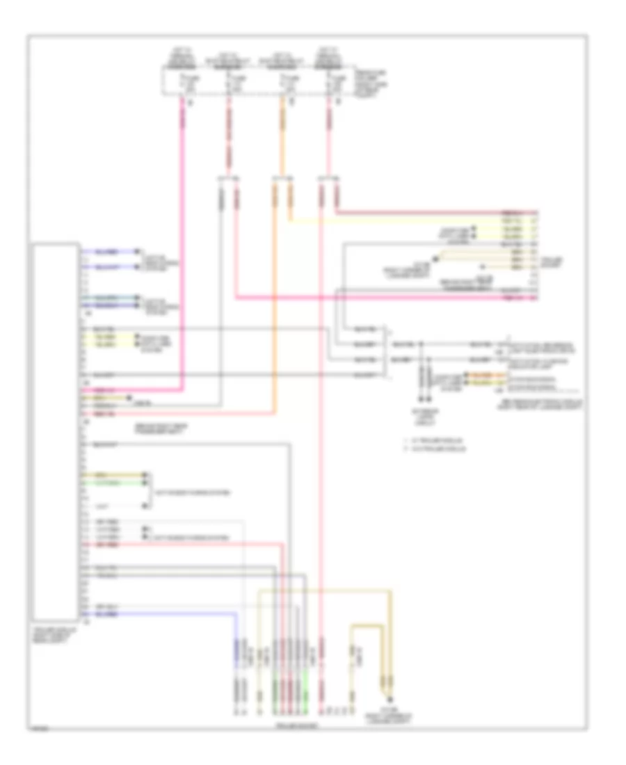
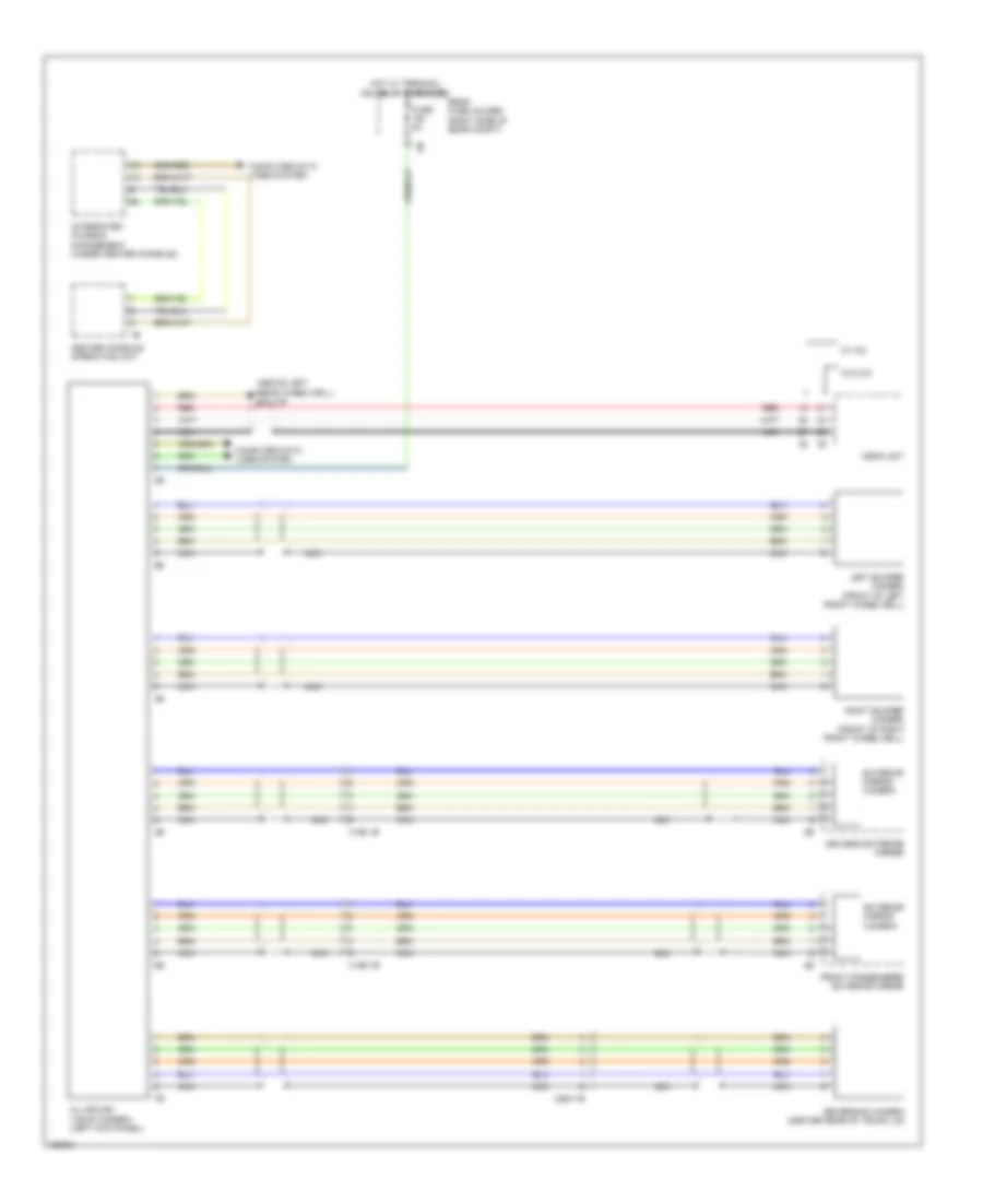
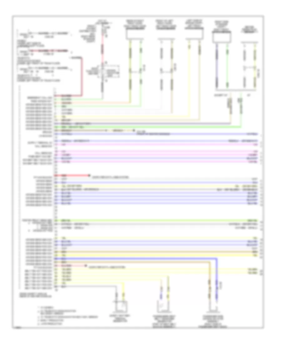
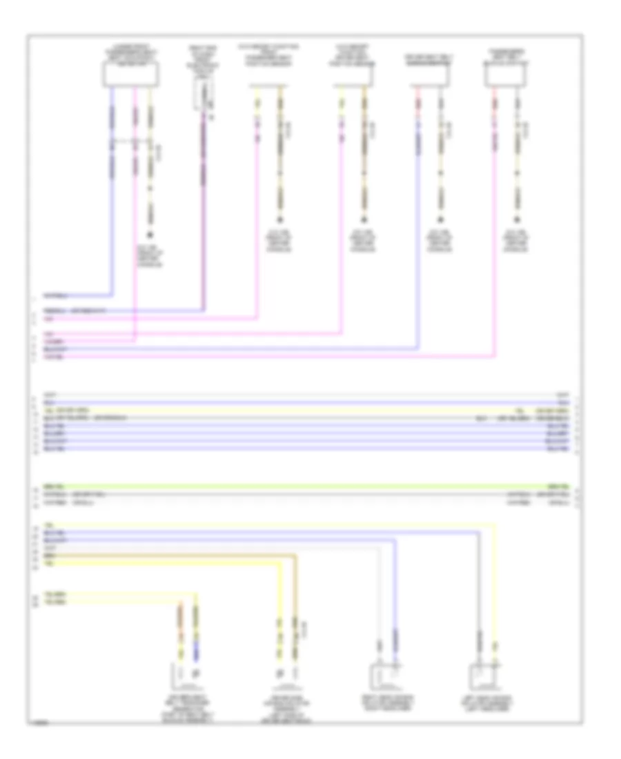
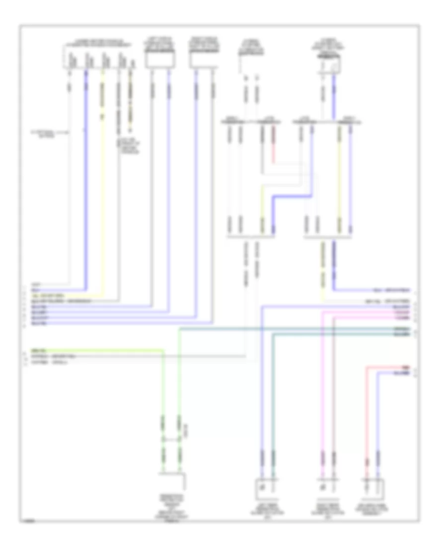
Trailer Tow Wiring Diagram, Late Production for BMW ActiveHybrid 3 2014
List of elements for Trailer Tow Wiring Diagram, Late Production for BMW ActiveHybrid 3 2014:
- (behind right rear passenger seat)
- 12b
- 13b
- 14b
- Activation, flashing indicator lamp
- Activation, reversing light electronic drive
- Active bodyworks system
- Computer data lines system
- Exterior lamps circuit
- Fuse 20a
- Hot w/ bi-stable relay energized
- Hot w/ terminal 30b relay energized
- K-can bus signal
- Rear fuse holder (right side of rear compt)
- Rem rear electronic module (right rear of luggage compt)
- Trailer module (right side of rear compt)
- Trailer socket
- W/ trailer module
- W/o trailer module
- X268 1b
- X269 1b
- Z10 7b
- Z10 7b (behind right rear passenger seat)
- Z10 9b (right corner of luggage compt)
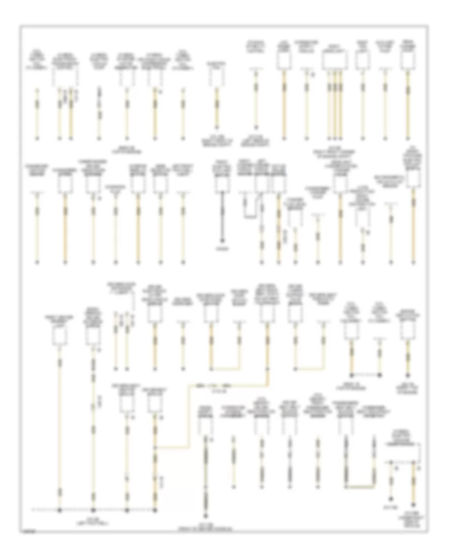
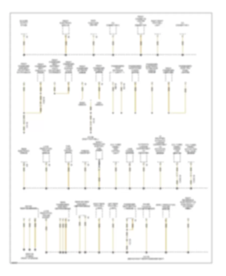
GROUND DISTRIBUTION
Ground Distribution Wiring Diagram (1 of 4) for BMW ActiveHybrid 3 2014
List of elements for Ground Distribution Wiring Diagram (1 of 4) for BMW ActiveHybrid 3 2014:
- (2.0l turbo) ignition coil cylinder 1
- (2.0l turbo) ignition coil cylinder 2
- (2.0l turbo) ignition coil cylinder 3
- (2.0l turbo) ignition coil cylinder 4
- (basic version) driver exterior mirror
- (hybrid) air conditioning compressor (electrical)
- (hybrid) electric machine electronics
- (hybrid) electric vacuum pump
- (hybrid) electronic transmission control
- (hybrid) starter motor generator
- (late production) front power distribution box
- (w/ sport package) electric coolant pump 2
- (w/o memory) driver seat-position sensor
- (w/o memory) front passenger seat-position sensor
- Active cruise control
- Auxiliary water pump
- Camera-based driver assistance systems
- Crash safety module
- Dashboard lighting center
- Diagnosis plug
- Driver electronic outer door handle module
- Driver lumbar support valve block
- Driver seat belt buckle contact
- Driver seat module
- Driver's door door panel lighting
- Driver's door entrance light
- Driver's door lock
- Driver's door switch block
- Driver's seat back- rest width adjustment valve block
- Driver's seat pneumatic pump
- Driver's seat- heating module
- Dynamic stability control
- E37 1b
- E82 1b
- Electric fan
- Engine ventilation heating
- Environmental air catalyst sensor
- Front center armrest light
- Front electric auxiliary
- Gear selector switch
- Headlight washer system washer pump
- Heater
- Integrated chassis management
- Interior rear lid button
- Left front footwell light
- Left washer nozzle heater
- Low range horn
- Nca
- Passenger seat occupancy detection
- Passenger's seat belt buckle contact
- Rear washer pump
- Right fog light
- Right headlight
- Right washer nozzle heater
- Washer fluid level sensor
- Windscreen washer pump
- Windscreen wiper
- X04000
- X14 1b
- X252 2b
- X28 1b
- X690 1b
- X719 1b
- Y21 1b
- Z10 10b (front of center console)
- Z10 15b (right front of engine compt)
- Z10 21b (left rear of engine compt)
- Z10 29b (under right side of vehicle)
- Z10 2b (right front corner of engine compt)
- Z10 3b (left footwell)
- Z10 70b
- Z23 1b (front top of engine)
- Z6000 1b (top of engine)
- Z6000 2b (top of engine)
Ground Distribution Wiring Diagram (2 of 4) for BMW ActiveHybrid 3 2014
List of elements for Ground Distribution Wiring Diagram (2 of 4) for BMW ActiveHybrid 3 2014:
- (2.0l turbo diesel) active tank fuel level sensor
- (2.0l turbo diesel) dosing line heating
- (2.0l turbo diesel) scr control unit
- (early production) electric fuel pump
- (early production) trailer module
- (if equipped) automatic luggage compartment lid actuation acoustic sensor
- (late production) trailer module
- (late production) trailer socket
- 12v connection 2
- 12v connection 3
- 14b
- Automatic luggage compartment lid actuation
- Basic version
- Blower output stage
- E21 1b
- E80 1b
- Front cigarette lighter 12v connection
- Front electronic module
- Front passenger door lock
- Front passenger exterior mirror
- Front passenger lumbar support valve block
- Front passenger seat backrest width adjustment valve block
- Front passenger seat pneumatic pump
- Front passenger side seat adjustment switch block
- Fuel pump control (ekps)
- High version
- Lane change warning
- Left rear footwell light
- Nca
- Parking assistant
- Passenger electronic outer door handle module
- Passenger seat-heating module
- Passenger's door entrance light
- Passenger's door power window switch
- Passenger's door trim panel lighting
- Power tailgate acoustic sensor
- Rear driver's side seat heating module
- Rear electronic module
- Rear passenger's side seat heating module
- Right front footwell light
- Right rear footwell light
- Right reversible electromotive electrically motorized reel
- Roof functions center
- Rotor position sensor
- X12 1b
- X1276 1b
- X5 1b
- X720 1b
- Z10 5b (right footwell)
- Z10 7b (behind right rear passenger seat)
- Z6000 3b (hybrid) (front of engine)
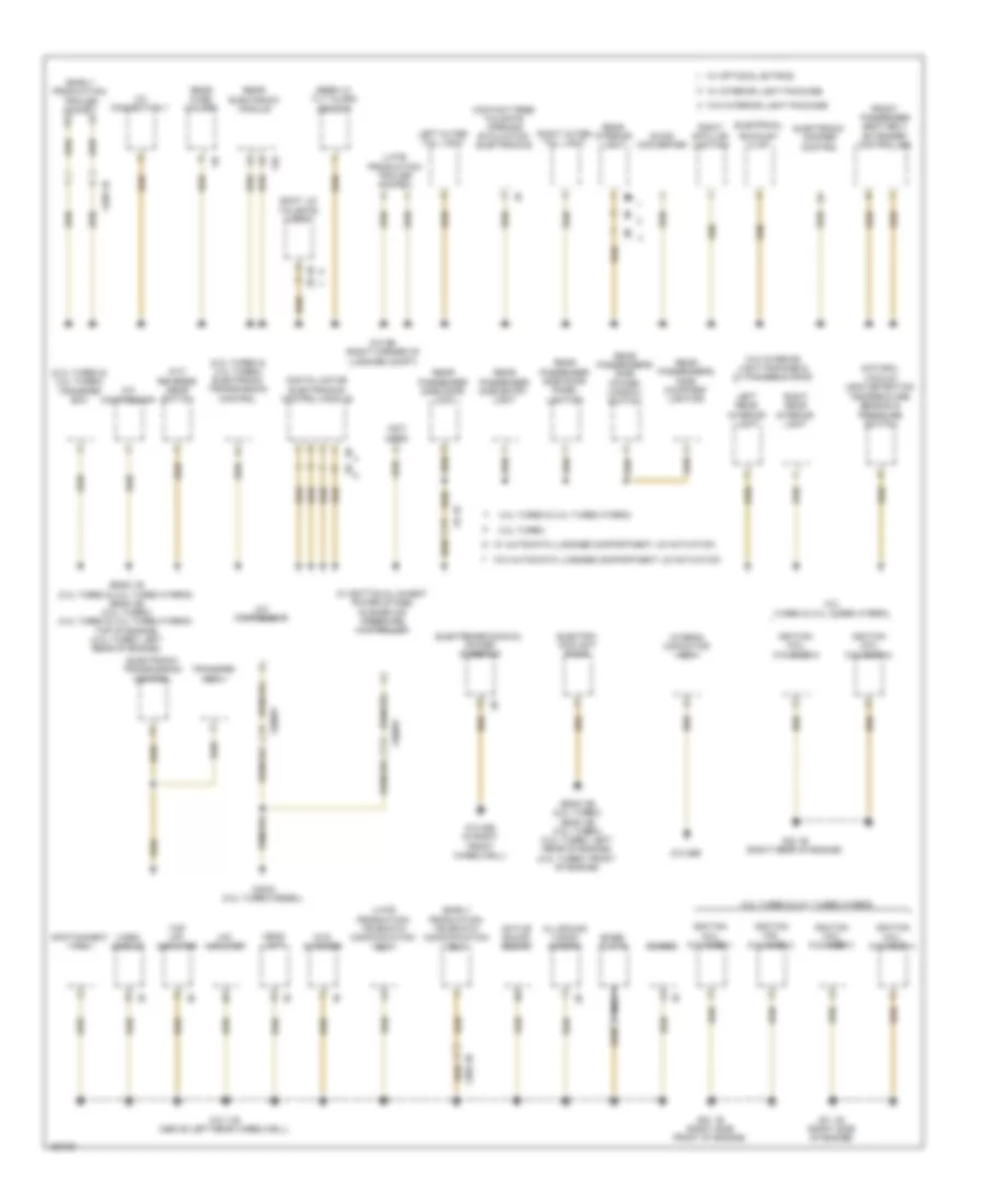
Ground Distribution Wiring Diagram (3 of 4) for BMW ActiveHybrid 3 2014
List of elements for Ground Distribution Wiring Diagram (3 of 4) for BMW ActiveHybrid 3 2014:
- (2.0l turbo & 3.0l turbo) electronic transmission control
- (2.0l turbo & 3.0l turbo) transfer box
- (early production) telematic communication box
- (early production) trailer socket
- (hybrid) capacitor box
- (late production) telematic communication box
- (late production) trailer socket
- (m/t) reverse gear switch
- (not used)
- (w/ bottom & lowest power stage) change air pressure controller
- 12b
- 12v connection 1
- 2.0l turbo
- 3.0l turbo & 3.0l turbo hybrid
- A/c compressor
- Active sound design
- All-round vision camera
- Base- plate
- Boot lid tailgate/ lock
- Combox
- Contact free tailgate opening evaluation electronics
- Dc/dc converter
- Digital motor electronics control module
- Dvd changer
- Electric coolant pump
- Electrical
- Electromechanical power steering
- Electronic damper control
- Electronic transmission control
- Exhaust flap
- Front passenger seat belt extender controller
- Head unit
- Hifi amplifier
- Ignition coil cylinder 1
- Ignition coil cylinder 2
- Ignition coil cylinder 3
- Ignition coil cylinder 4
- Ignition coil cylinder 5
- Ignition coil cylinder 6
- Infotainment fan
- Left outer tail light
- Left rear interior light
- Natural vacuum leak detection temperature sensor & pressure switch
- Nca
- Rear electronic module
- Rear fuse holder
- Rear interior light
- Rear passenger side door lock
- Rear passenger side door panel lighting
- Rear passenger side entry light
- Rear passenger's side courtesy lighting
- Rear passenger's side power window switch
- Right b-pillar lighting
- Right outer tail light
- Right rear interior light
- Siren w/ tilt alarm sensor
- Top hifi amplifier
- Transfer box
- Video module
- W/ automatic luggage compartment lid actuation
- W/ interior light package
- W/ optional extras
- W/o automatic luggage compartment lid actuation
- W/o interior light package
- W/o interior light package & w/ panorama roof
- X2042 (2.0l turbo diesel)
- X268 1b
- X382 3b
- X60681
- X9 1b
- Z10 11b (above left rear wheelwell)
- Z10 20b (in right front wheelwell)
- Z10 26b
- Z10 9b (right corner of luggage compt)
- Z20 1b (right side front of engine)
- Z21 1b (right side of engine)
- Z22 1b (right rear of engine)
- Z6000 1b (3.0l turbo & 3.0l turbo hybrid) z6000 4b (2.0l turbo) (3.0l turbo & 3.0l turbo hybrid: top of engine) (2.0l turbo: left rear of engine)
- Z6000 3b (2.0l turbo) z6000 4b (3.0l turbo) (3.0l turbo: left rear of engine) (2.0l turbo: front of engine)
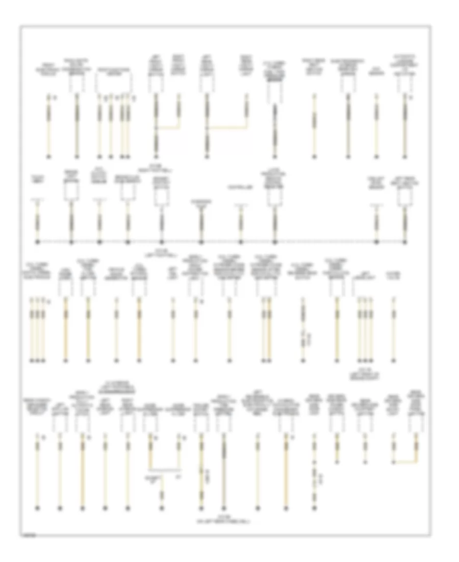
Ground Distribution Wiring Diagram (4 of 4) for BMW ActiveHybrid 3 2014
List of elements for Ground Distribution Wiring Diagram (4 of 4) for BMW ActiveHybrid 3 2014:
- (2.0l turbo diesel) diesel particulate sensor
- (2.0l turbo diesel) digital diesel electronics
- (2.0l turbo diesel) fuel filter heating
- (2.0l turbo diesel) nitrogen oxide sensor after scr catalytic converter
- (2.0l turbo diesel) nitrogen oxide sensor before scr catalytic converter
- (2.0l turbo diesel) reverse gear switch
- (2.0l turbo) ethanol sensor
- (3.0l turbo hybrid) fuel tank pressure sensor
- (early production) front power distribution box
- (early production) fully automatic towing hitch
- (early production) tire pressure control
- (hybrid) accumulator management electronics
- (late production) remote control receiver
- (m/t) clutch switch module
- 11b
- 12b
- Auc sensor
- Automatic luggage compartment lid actuation
- Bonnet contact switch
- Brake fluid level switch
- Brake light switch
- Controller
- Coolant level sensor
- Diagnosis plug
- Driver's side rear power window switch
- Electrochromic interior rearview mirror
- Except gt
- Front electronic module
- High range horn
- Left b-pillar lighting
- Left fog light
- Left front vanity mirror switch
- Left headlight
- Left rear interior light
- Left rear seat heating switch
- Left rear vanity mirror light
- Left reversible electromotive electrically motorized reel
- Nca
- Noise suppressor filter
- Rain/lights/ solar/ condensation sensor
- Rear driver's side courtesy lighting
- Rear driver's side door lock
- Rear driver's side door panel lighting
- Rear driver's side entry light
- Rear window defogger rejector circuit
- Right front vanity mirror switch
- Right rear interior light
- Right rear seat heating switch
- Right rear vanity mirror light
- Roof functions center
- Touch box
- Trailer socket switch
- Vehicle sound generator
- W/ interior light package & w/ panorama roof
- Water valve
- X13 4b
- X269 1b
- X8 1b
- Z10 1b (left front of engine compt)
- Z10 4b (left footwell)
- Z10 6b (right footwell)
- Z10 8b (on left rear wheelwell)
HEADLIGHTS
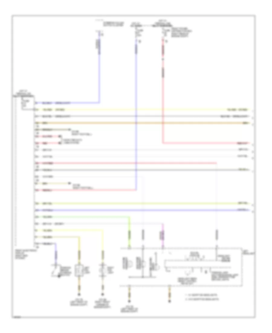
Headlights Wiring Diagram, with Xenon Lamps (1 of 2) for BMW ActiveHybrid 3 2014
List of elements for Headlights Wiring Diagram, with Xenon Lamps (1 of 2) for BMW ActiveHybrid 3 2014:
- (or red)
- 10b
- Bi-xenon shutter
- Computer data lines system
- Daytime driving
- Daytime running lamp parking/lamp/ side lamp/ daytime driving light
- Front electronic module (right end of dash)
- Front power distribution box (right rear of engine compt)
- Fuse 40a
- Fuse 5a
- Headlight beam height control drive unit
- Headlight driver module
- Hot at all times
- Hot w/ terminal 30b relay energized
- Hot w/ terminal 30f relay energized
- Left fog light
- Left headlight
- Lights
- Parking brake warning switch
- Right fog light
- Steering column switch cluster
- Swivel module
- W/ adaptive headlights
- W/o adaptive headlights
- Xenon lamp bulb
- Xenon light module
- Z10 1b (left front of engine compt)
- Z10 2b (right front corner of engine compt)
- Z10 5b (right footwell)
- Z10 6b (right footwell)
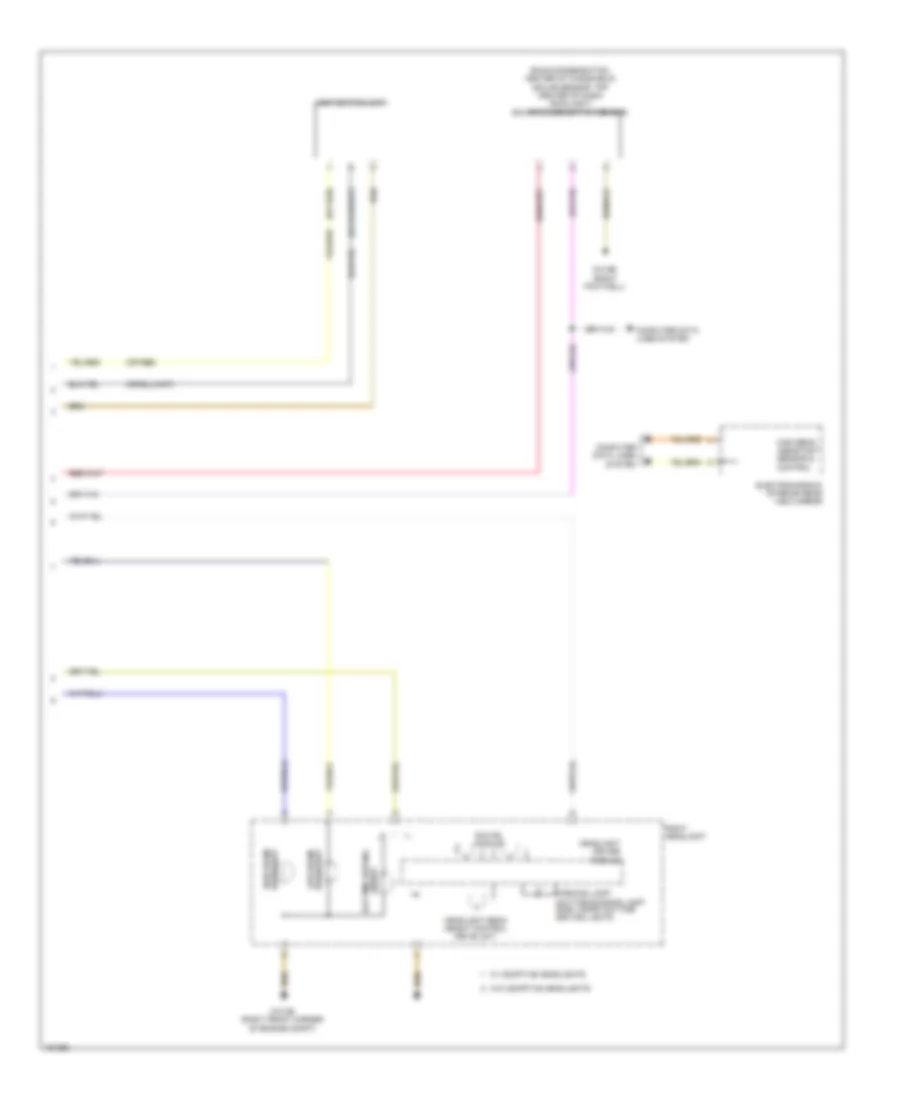
Headlights Wiring Diagram, with Xenon Lamps (2 of 2) for BMW ActiveHybrid 3 2014
List of elements for Headlights Wiring Diagram, with Xenon Lamps (2 of 2) for BMW ActiveHybrid 3 2014:
- (or red)
- (rain/condensation: center of windshield) (solar sensor: top center of dash) rain/light/solar/ condensation sensor
- Bi-xenon shutter
- Computer data lines system
- Daytime driving
- Daytime running lamps/ parking lamps/ side lights
- Electrochromic interior rear view mirror
- Headlight beam height control drive unit
- Headlight driver module
- High beam assistant sensor & control
- Light switch unit
- Lights
- Right headlight
- Swivel module
- W/ adaptive headlights
- W/o adaptive headlights
- Xenon lamp bulb
- Xenon light module
- Z10 2b (right front corner of engine compt)
- Z10 6b (right footwell)
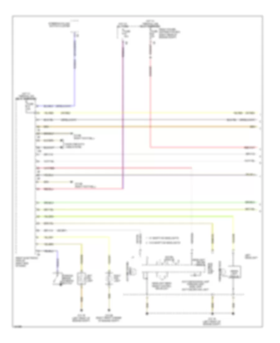
Headlights Wiring Diagram, without Xenon Lamps (1 of 2) for BMW ActiveHybrid 3 2014
List of elements for Headlights Wiring Diagram, without Xenon Lamps (1 of 2) for BMW ActiveHybrid 3 2014:
- (or red)
- Computer data lines system
- Daytime driving
- Front electronic module (right end of dash)
- Front power distribution box (right rear of engine compt)
- Fuse 40a
- Fuse 5a
- Headlight beam height control drive unit
- Headlight driver module
- Headlight high beam
- Hot at all times
- Hot w/ terminal 30b relay energized
- Hot w/ terminal 30f relay energized
- Left fog light
- Left headlight
- Lights
- Low beam headlight
- Parking brake warning switch
- Parking lamp/ daytime running lamp/ side lamps/daytime driving lights
- Red
- Right fog light
- Steering column switch cluster
- Swivel module
- W/ adaptive headlights
- W/o adaptive headlights
- Z10 1b (left front of engine compt)
- Z10 2b (right front corner of engine compt)
- Z10 5b (right footwell)
- Z10 6b (right footwell)
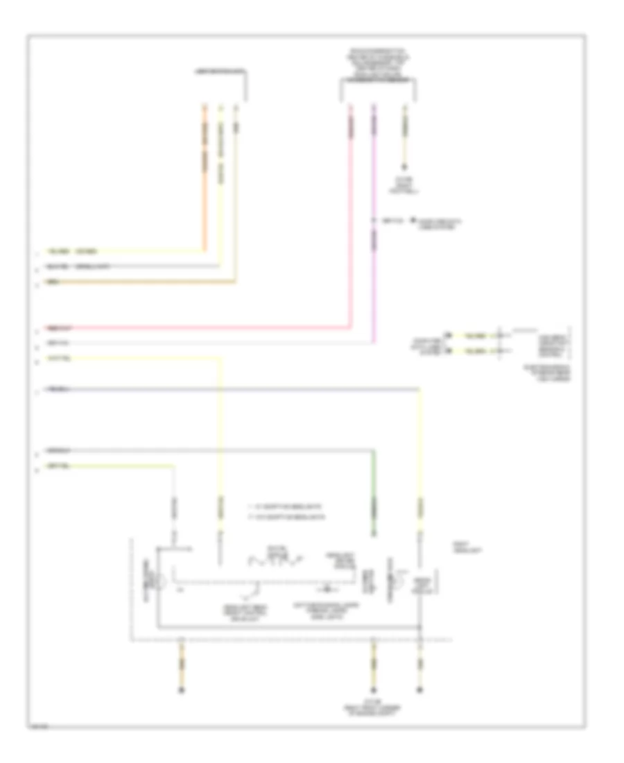
Headlights Wiring Diagram, without Xenon Lamps (2 of 2) for BMW ActiveHybrid 3 2014
List of elements for Headlights Wiring Diagram, without Xenon Lamps (2 of 2) for BMW ActiveHybrid 3 2014:
- (or red)
- (rain/condensation: center of windshield) (solar sensor: top center of dash) rain/light/ solar/condensation sensor
- Computer data lines system
- Daytime driving
- Electrochromic interior rear view mirror
- Headlight beam height control drive unit
- Headlight driver module
- Headlight high beam
- High beam assistant sensor & control
- Light switch unit
- Lights
- Low beam headlight
- Parking lamp/ daytime running lamp/ side lamps/ daytime driving lights
- Right headlight
- Swivel module
- W/ adaptive headlights
- W/o adaptive headlights
- Z10 2b (right front corner of engine compt)
- Z10 6b (right footwell)
HORN
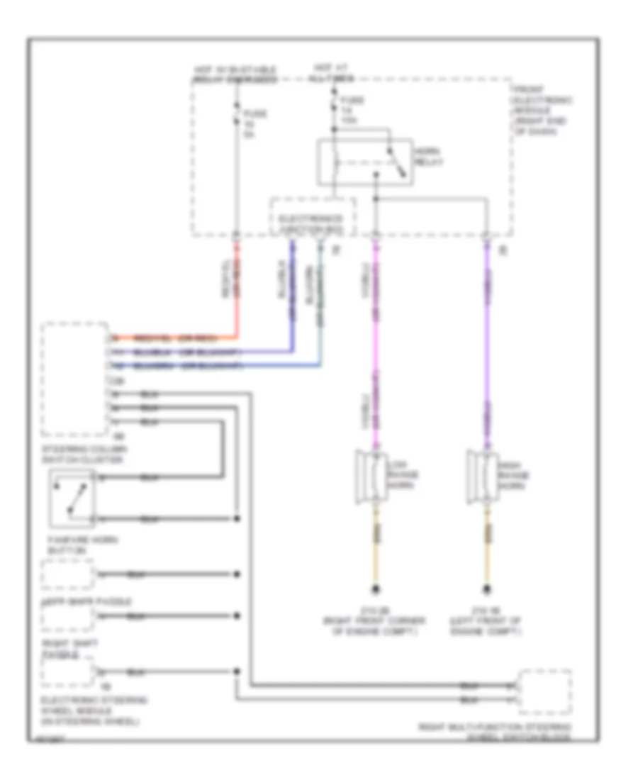
Horn Wiring Diagram for BMW ActiveHybrid 3 2014
List of elements for Horn Wiring Diagram for BMW ActiveHybrid 3 2014:
- (or red)
- Electronic steering wheel module (in steering wheel)
- Electronics junction box
- Fanfare horn button
- Front electronic module (right end of dash)
- Fuse 15a
- Fuse 5a
- High range horn
- Horn relay
- Hot at all times
- Hot w/ bi-stable relay energized
- Left shift paddle
- Low range horn
- Right multi-function steering wheel switch block
- Right shift paddle
- Steering column switch cluster
- Z10 1b (left front of engine compt)
- Z10 2b (right front corner of engine compt)
INSTRUMENT CLUSTER
Instrument Cluster Wiring Diagram for BMW ActiveHybrid 3 2014
List of elements for Instrument Cluster Wiring Diagram for BMW ActiveHybrid 3 2014:
- (or red)
- (right footwell)
- 10b
- 14b
- Computer data lines system
- Coolant level sensor (right side of engine compt)
- Early production
- Front electronic module (right end of dash)
- Front power distribution box (right rear of engine compt)
- Fuel level sensor
- Fuel level sensor 2
- Fuse 5a
- Fuse 7.5a
- Head-up display
- Hot at all times
- Hot w/ terminal 30b relay energized
- Instrument cluster control unit
- Late production
- Nca
- Outside temperature sensor (front center of bumper)
- Parking brake warning switch (under center console)
- Rear electronic module (right rear of luggage compt)
- Red
- Sound systems
- X94 1b
- X94 3b
- Z10 4b (left footwell)
- Z10 5b
INTERIOR LIGHTS
Courtesy Lamps Wiring Diagram (1 of 2) for BMW ActiveHybrid 3 2014
List of elements for Courtesy Lamps Wiring Diagram (1 of 2) for BMW ActiveHybrid 3 2014:
- (or red)
- (right corner of luggage compt) z10 9b
- (right footwell) z10 6b
- 11b
- 13b
- 14b
- Ambient light
- Boot lid/ tailgate lock
- Computer data lines system
- Front power distribution box (right rear of engine compt)
- Fuse 40a
- Fuse 5a
- Glove compartment light
- Glove compartment light switch
- Hot at all times
- Hot w/ terminal 30b relay energized
- Instrument illumination circuit
- Interior light
- Left front vanity mirror light
- Left front vanity mirror switch
- Left map reading light
- Lights welcome
- Luggage compartment light
- Reading light right map
- Rear fuse holder (right side of rear compt)
- Rear interior light (w/ high lights package)
- Rear interior light (w/ low lights package)
- Red/
- Rem rear electronic module (right rear of luggage compt)
- Right front vanity mirror light
- Right front vanity mirror switch
- Right map reading light
- Roof function center (w/ high lights package)
- Roof function center (w/ low lights package)
- W/ high lights package
- W/ interior lights package
- W/ low lights package
- W/o interior lights package
- Welcome lights
- Z10 6b (right footwell)
- Z10 7b (behind right rear passenger seat)
- Z10 9b (right corner of luggage compt)
Courtesy Lamps Wiring Diagram (2 of 2) for BMW ActiveHybrid 3 2014
List of elements for Courtesy Lamps Wiring Diagram (2 of 2) for BMW ActiveHybrid 3 2014:
- (right footwell) z10 5b
- 12b
- Computer data lines system
- Driver's door entrance light
- Driver's side entry light
- E21
- E37
- E80
- E82
- Fem front electronic module (right end of dash)
- Instrument illumination circuit
- Interior light
- Left front footwell light
- Passenger's door entrance light
- Rear
- Rear driver's side courtesy lighting
- Rear interior light
- Rear passenger's side courtesy lighting
- Rear passenger's side entry light
- Right front footwell light
- Roof function center (w/o interior lights package)
- X28 1b
- X5 1b
- X8 1b
- X9 1b
- Z10 3b (left footwell)
- Z10 5b (right footwell)
- Z10 6b (right footwell)
- Z10 8b (on left rear wheelwell)
- Z10 9b (right corner of luggage compt)
Instrument Illumination Wiring Diagram (1 of 2) for BMW ActiveHybrid 3 2014
List of elements for Instrument Illumination Wiring Diagram (1 of 2) for BMW ActiveHybrid 3 2014:
- (or red)
- (right footwell) z10 5b
- (w/ high lights package) rear interior light
- (w/ high lights package) roof function center
- 10b
- 11b
- Ambient light
- Central locking button operating unit hazard warning switch
- Compt)
- Computer data lines system
- Driver's door panel lighting
- Driver's side rear power window switch
- Dvd changer
- Fem front electronic module (right end of dash)
- Front center ventilation grille
- Fuse 5a
- Head unit
- Heating/air conditioning system (center of dash, above radio)
- Hot w/ terminal 30f relay energized
- Interior light
- Left front footwell light
- Left lighting b-pillar
- Left rear interior light (sports wagon)
- Light interior
- Light switch unit
- Lighting center of dash board
- Nca
- Passenger's door power window switch
- Passenger's door trim panel lighting
- Passenger's side rear power window switch
- Reading light left map
- Reading light right map
- Rear driver's side door panel lighting
- Rear passenger's side door panel lighting
- Right lighting b-pillar
- Right rear interior light (sports wagon)
- W/ dvd changer
- W/ high lights package
- W/ low lights package
- W/o dvd changer
- Welcome lights
- X28 1b
- X4711
- X5 1b
- X8 1b
- X9 1b
- Z10 11b (above left rear wheelwell)
- Z10 3b (left footwell)
- Z10 5b (right footwell)
- Z10 6b (right footwell)
- Z10 8b (on left rear wheelwell)
- Z10 9b (right corner of luggage compt)
Instrument Illumination Wiring Diagram (2 of 2) for BMW ActiveHybrid 3 2014
List of elements for Instrument Illumination Wiring Diagram (2 of 2) for BMW ActiveHybrid 3 2014:
- (w/ low lights package) roof function center
- (w/o interior lights package) roof function center
- 11b
- 12b
- Center console control panel
- Front center armrest light
- Gear shift lever lighting
- Integrated chassis management (under center console)
- Interior light
- Interior rear lid button
- Right front footwell light
- Z10 10b (front of center console)
- Z10 3b (left footwell)
- Z10 5b (right footwell)
- Z10 6b (right footwell)
MEMORY SYSTEMS
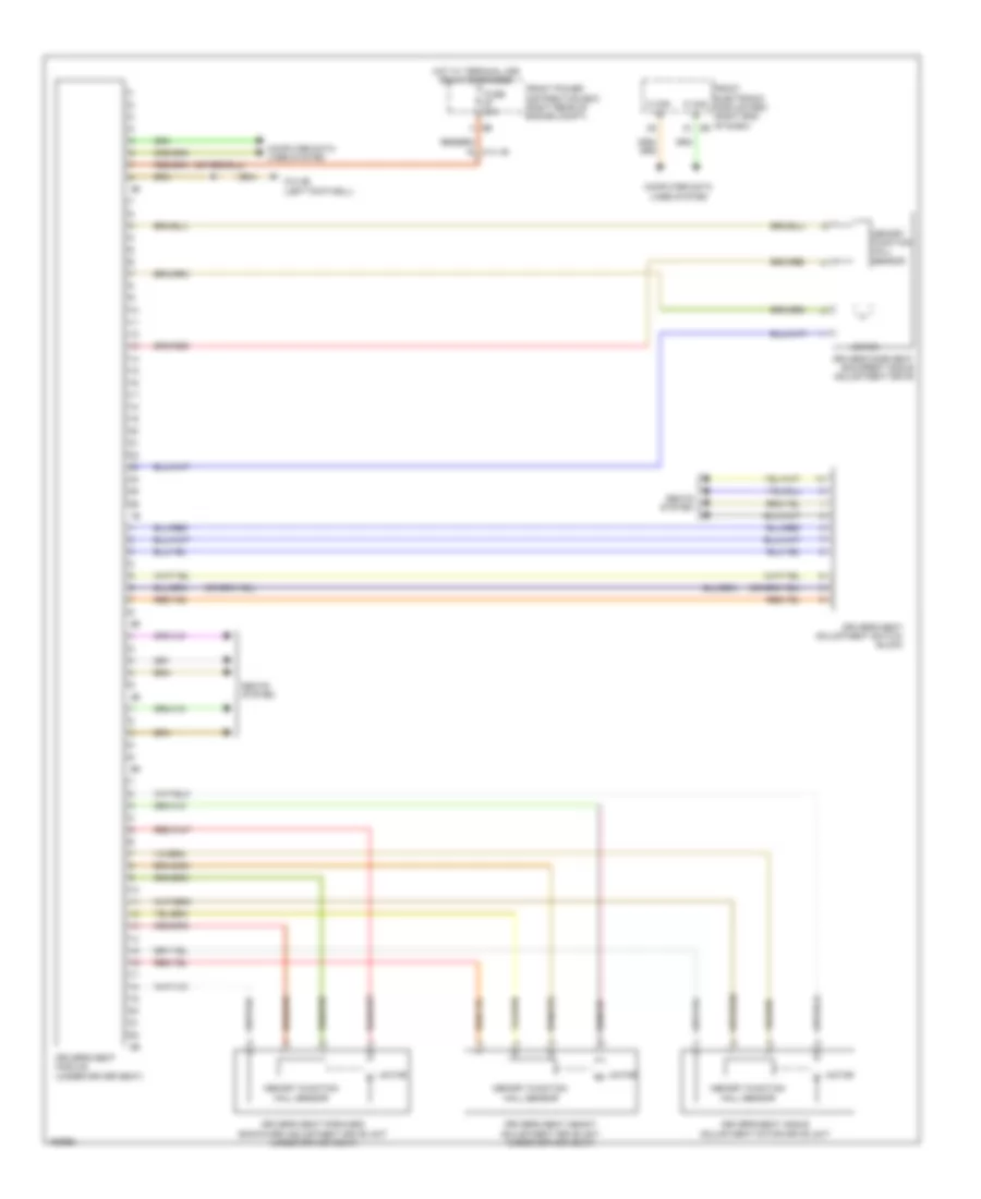
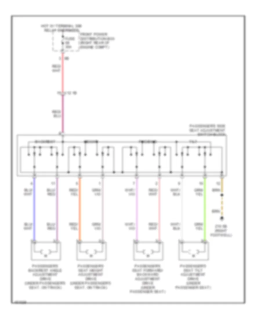
Driver"s Memory Seat Wiring Diagram for BMW ActiveHybrid 3 2014
List of elements for Driver"s Memory Seat Wiring Diagram for BMW ActiveHybrid 3 2014:
- Computer data lines system
- Driver's seat adjustment switch block
- Driver's seat angle adjustment motor drive unit
- Driver's seat forward/ backward adjustment drive unit (under driver seat)
- Driver's seat height adjustment drive unit (under driver seat)
- Driver's seat module (under driver seat)
- Driver's side seat backrest angle adjustment drive
- Front electronic module (fem) (right end of dash) 8b
- Front power distribution box (right rear of engine compt)
- Fuse 30a
- Hot w/ terminal 30b relay energized
- K can h
- K can l
- Memory function hall sensor
- Motor
- Seats system
- X14 1b
- Z10 3b (left footwell)
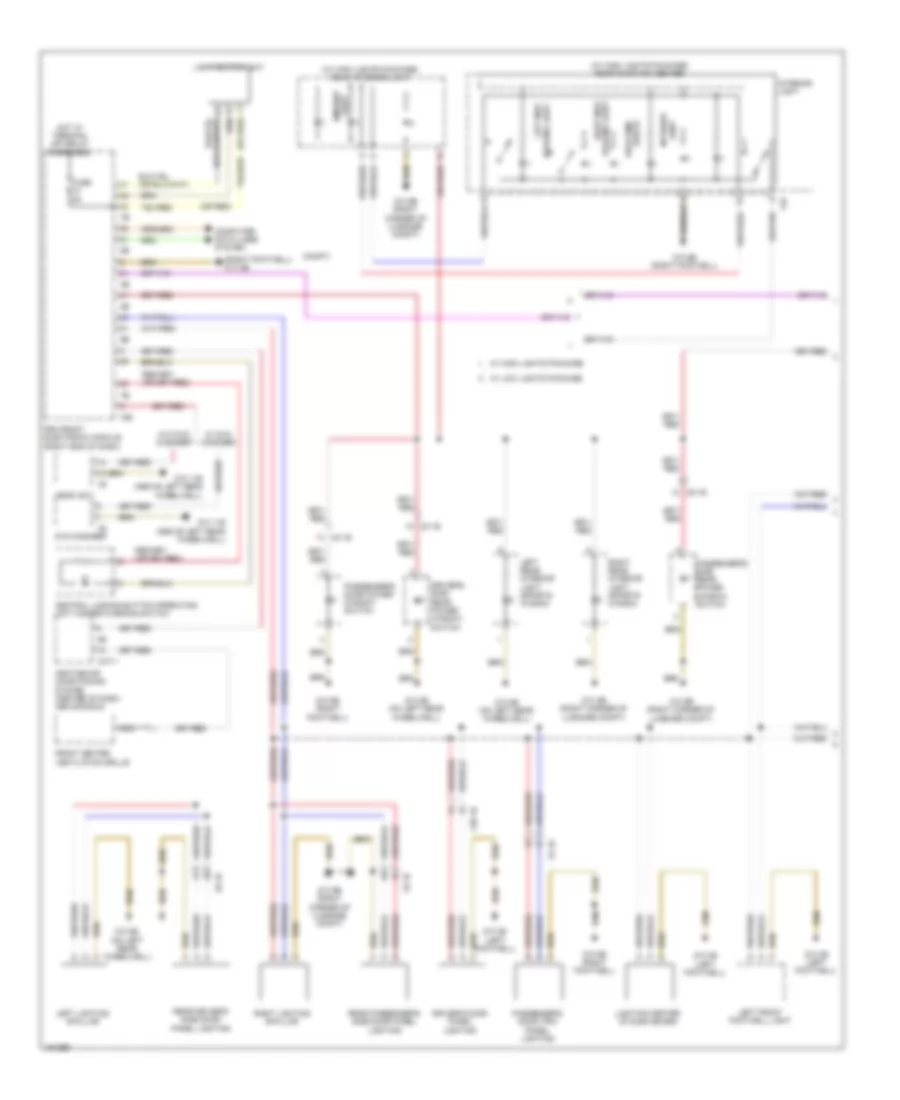
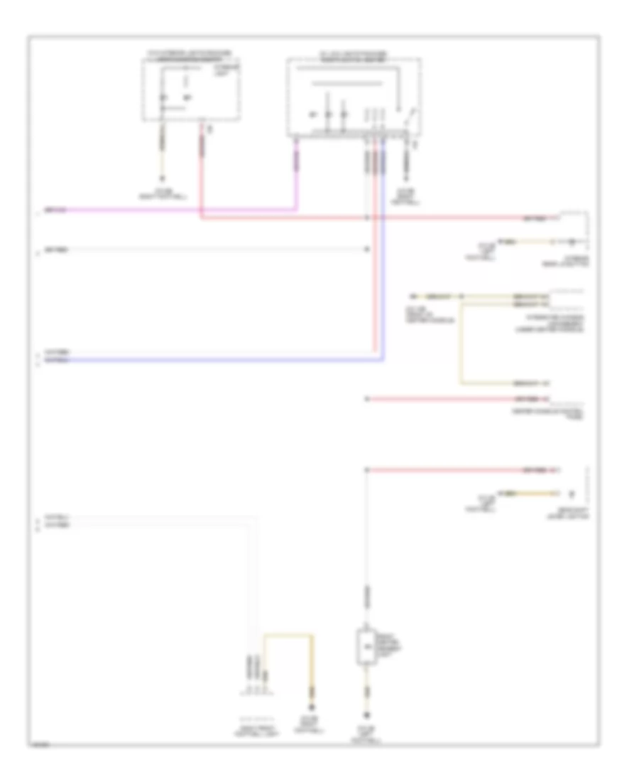
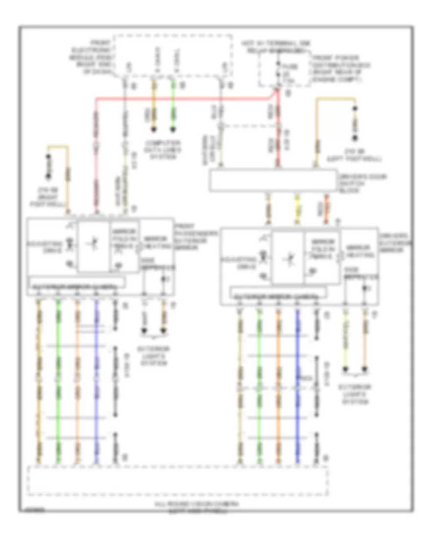
Memory Mirrors Wiring Diagram, with LIN bus Function for BMW ActiveHybrid 3 2014
List of elements for Memory Mirrors Wiring Diagram, with LIN bus Function for BMW ActiveHybrid 3 2014:
- Adjusting drive
- All round vision camera (left kick panel)
- Computer data lines system
- Driver's door switch block
- Driver's exterior mirror
- Exterior lights system
- Exterior mirror camera
- Front electronic module (fem) (right end of dash)
- Front passenger's exterior mirror
- Front power distribution box (right rear of engine compt)
- Fuse 7.5a
- Hot w/ terminal 30b relay energized
- K can h
- K can l
- Lin
- Mirror fold in drive
- Mirror heating
- Nca
- Side repeater
- X199 1b
- X28 1b
- X5 1b
- Z10 3b (left footwell)
- Z10 5b (right footwell)
Memory Mirrors Wiring Diagram, without LIN bus Function for BMW ActiveHybrid 3 2014
List of elements for Memory Mirrors Wiring Diagram, without LIN bus Function for BMW ActiveHybrid 3 2014:
- Adjustment drive
- All round vision camera (left kick panel)
- Camera
- Computer data lines system
- Driver's door switch block
- Driver's exterior mirror
- Exterior lights system
- Exterior mirror
- Front electronic module (right end of dash)
- Front passenger's exterior mirror
- Front power distribution box (right rear of engine compt)
- Fuse 7.5a
- Hot w/ terminal 30b relay energized
- K can h
- K can l
- Mirror heating
- Nca
- Power distribution system
- Side repeater
- X198 1b
- X199 1b
- X28 1b
- X5 1b
- Z10 3b (left footwell)
- Z10 5b (right footwell)
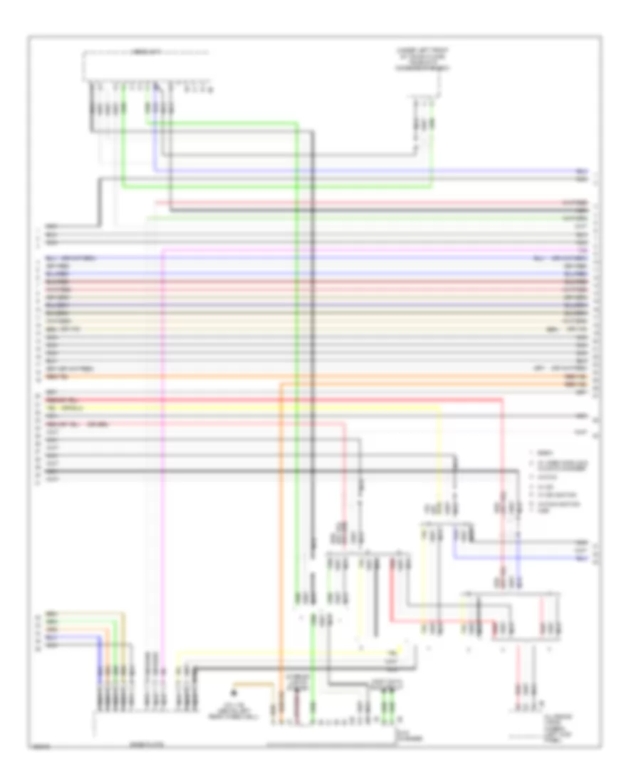
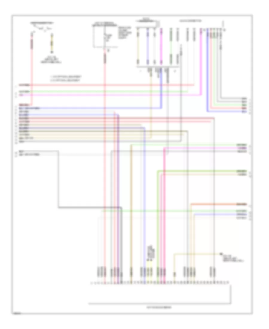
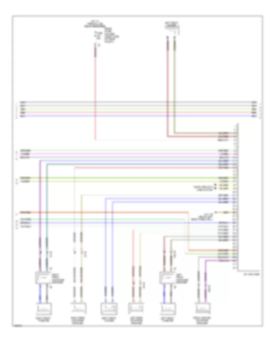
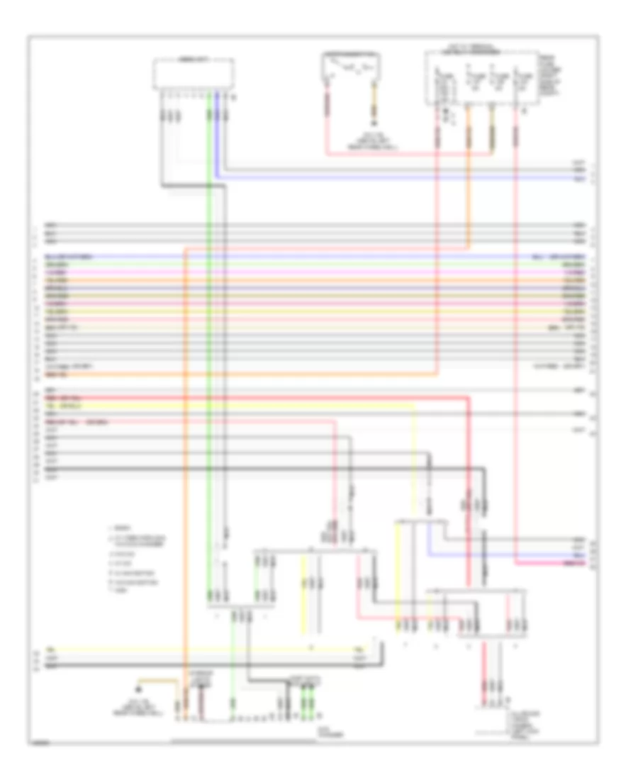
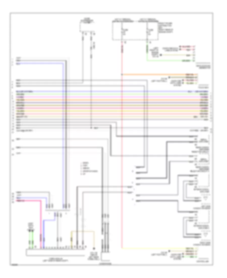
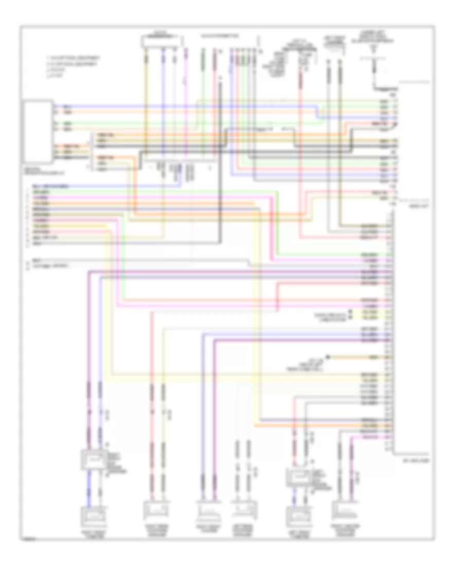
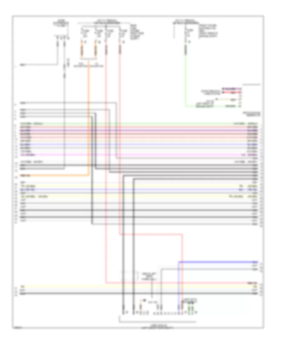
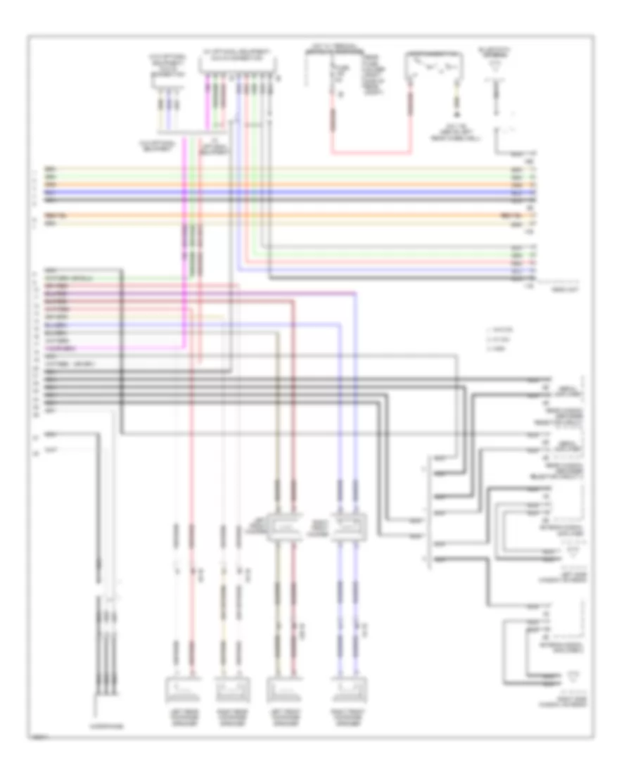
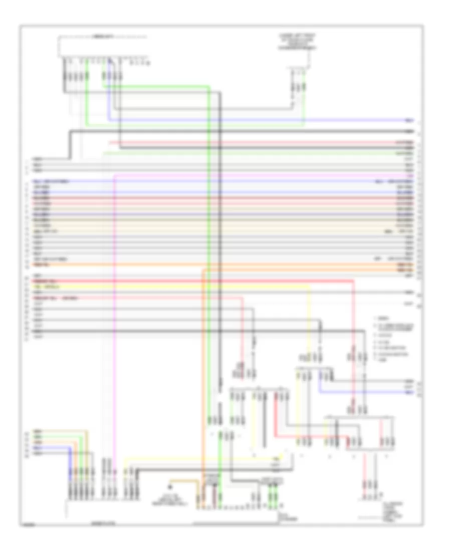
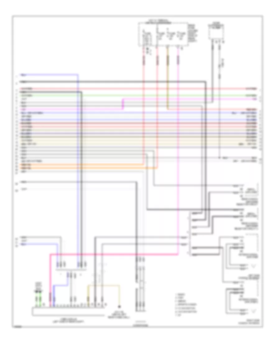
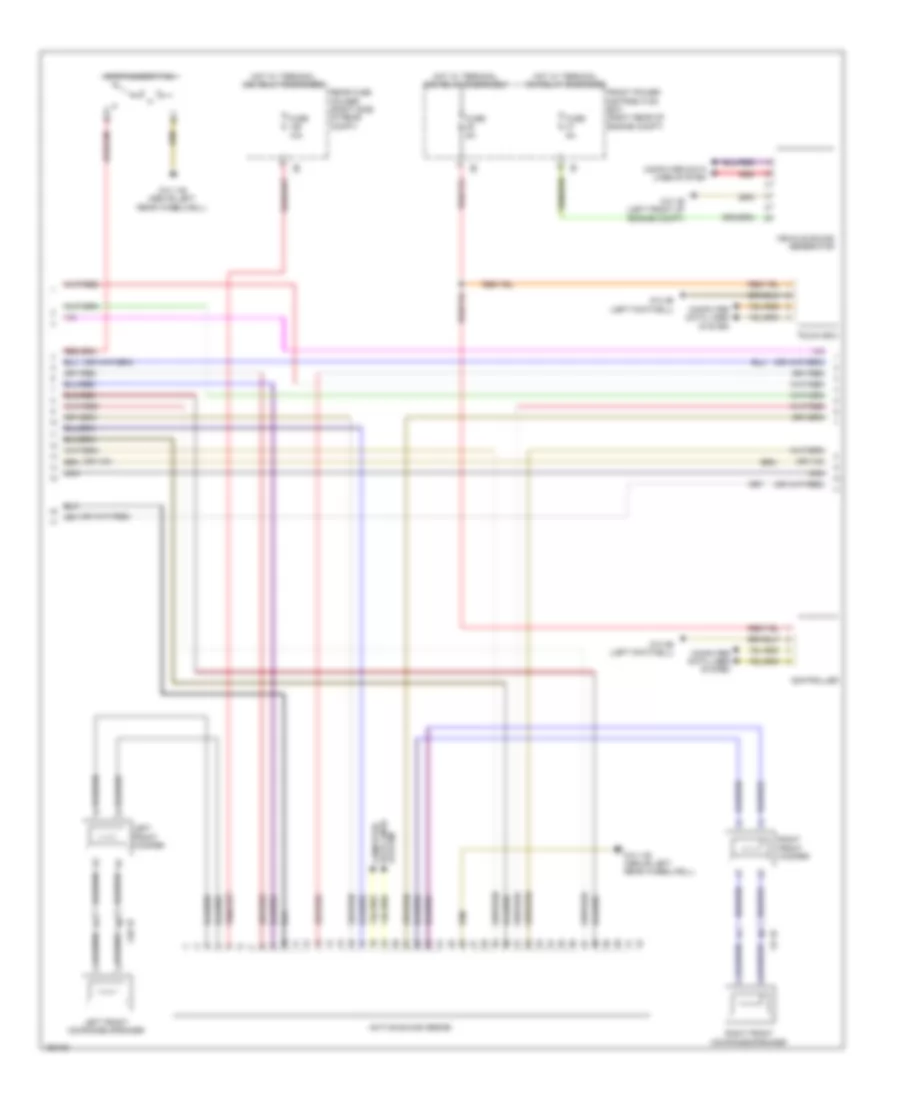
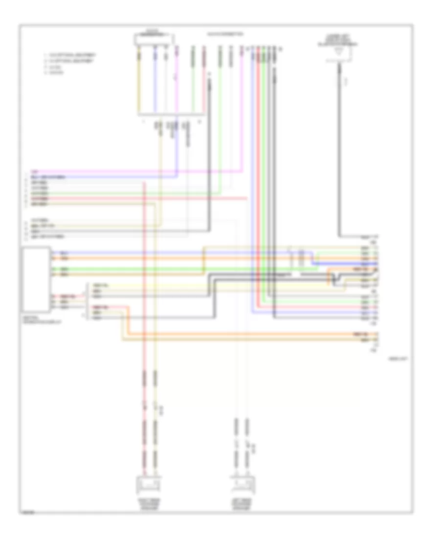
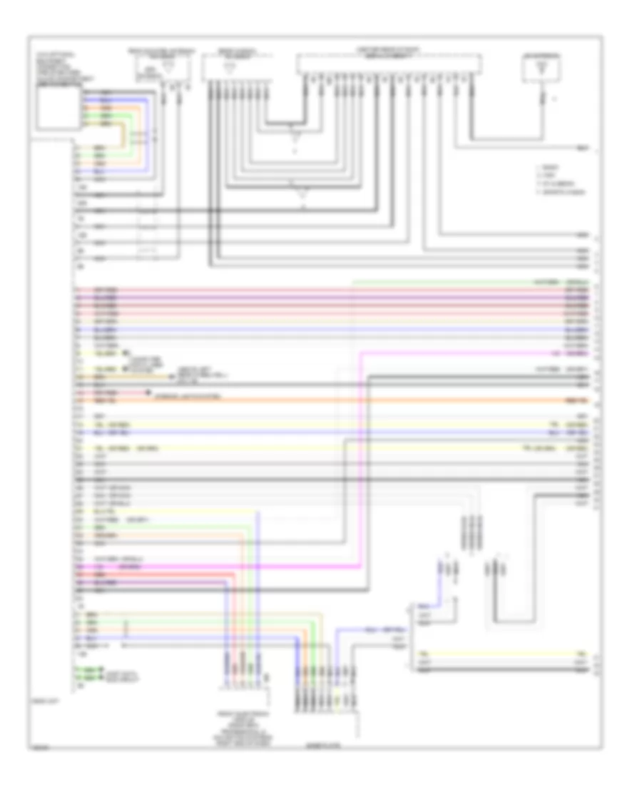
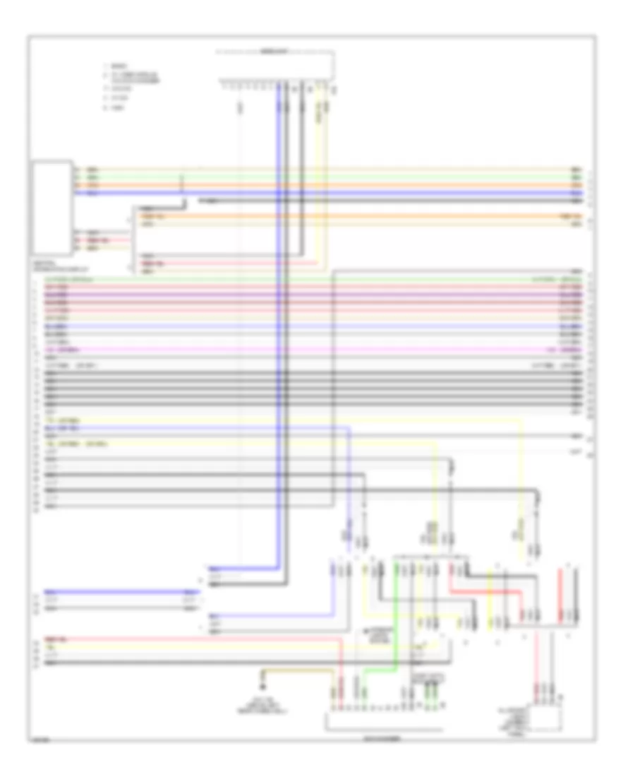
NAVIGATION
All Around Vision Camera Wiring Diagram for BMW ActiveHybrid 3 2014
List of elements for All Around Vision Camera Wiring Diagram for BMW ActiveHybrid 3 2014:
- (above left rear wheelwell) z10 11b
- All-round vision camera (left kick panel)
- Center console operating unit
- Computer data lines system
- Driver's exterior mirror
- Exterior mirror camera
- Front passenger's exterior mirror
- Fuse 5a
- Head unit
- Hot w/ terminal 15n relay energized
- Integrated chassis management (under center console)
- Left bumper camera (front of left front wheelwell)
- Nca
- Rear fuse holder (right side of rear compt)
- Red
- Reversing camera (center rear of trunk lid)
- Right bumper camera (front of right front wheelwell)
- W/ cic
- W/o cic
- X198 1b
- X199 1b
- X583 1b
Lane Departure Warning Wiring Diagram, with Camera for BMW ActiveHybrid 3 2014
List of elements for Lane Departure Warning Wiring Diagram, with Camera for BMW ActiveHybrid 3 2014:
- (or red)
- Camera-based driver assistance systems
- Camera-based driver support systems (left kick panel)
- Computer data lines system
- Driver assistance systems operating unit
- Front electronic module (right end of dash)
- Front power distribution box (right rear of engine compt)
- Fuse 5a
- Hot w/ terminal 15n relay energized
- Hot w/ terminal 30f relay energized
- Lane departure warning camera (top center of windshield)
- Nca
- Red
- Z10 3b (left footwell)
- Z10 5b (right footwell)
Lane Departure Warning Wiring Diagram, without Camera for BMW ActiveHybrid 3 2014
List of elements for Lane Departure Warning Wiring Diagram, without Camera for BMW ActiveHybrid 3 2014:
- Driver's door switch block
- Driver's exterior mirror
- Fem front electronic module (right end of dash)
- Front passenger exterior mirror
- Fuse 5a
- Hot w/ terminal 15n relay energized
- Lane change warning (right corner of rear bumper)
- Lane change warning slave (left corner of rear bumper)
- Pnk
- Rear fuse holder (right side of rear compt)
- Steering column switch cluster
- X28 1b
- X5 1b
- Z10 7b (behind right rear passenger seat)
Navigation Wiring Diagram, with Hifi Radio & Active Sound Design (1 of 6) for BMW ActiveHybrid 3 2014
List of elements for Navigation Wiring Diagram, with Hifi Radio & Active Sound Design (1 of 6) for BMW ActiveHybrid 3 2014:
- (above left rear wheelwell) z10 11b
- (center rear of roof) aerial diversity
- 10b
- 13b
- 14b
- 18b
- 20b
- Am antenna
- Computer data lines system
- Fem front electronic module (radio bmw professional & navigation systems) (right end of dash)
- Glove compartment usb connection (w/o optional equipment connection mobile devices)
- Gps antenna
- Gt & sedan
- Head unit
- Interior lights system
- Most data bus circuit
- Nca
- Rear window antenna
- Red
- Roof aerial
- Sports wagon
Navigation Wiring Diagram, with Hifi Radio & Active Sound Design (2 of 6) for BMW ActiveHybrid 3 2014
List of elements for Navigation Wiring Diagram, with Hifi Radio & Active Sound Design (2 of 6) for BMW ActiveHybrid 3 2014:
- (under left front of trunk floor) telematic communication box
- All-round vision camera (left kick panel)
- Base plate
- Basic
- Dvd changer
- Head unit
- High
- Interior lights system
- Most data bus circuit
- Nca
- Red
- W/ cic
- W/ navigation
- W/ video module &
- W/o cic
- W/o dvd changer
- W/o navigation
- Z10 11b (above left rear wheelwell)
Navigation Wiring Diagram, with Hifi Radio & Active Sound Design (3 of 6) for BMW ActiveHybrid 3 2014
List of elements for Navigation Wiring Diagram, with Hifi Radio & Active Sound Design (3 of 6) for BMW ActiveHybrid 3 2014:
- Aerial amplifier
- Antenna signal amplifier
- Antenna signal amplifier 2
- Basic
- Fuse 20a 15a
- Fuse 5a
- High
- Hot w/ terminal 30b relay energized
- Left side window antenna
- Microphone
- Most data bus circuit
- Nca
- Noise suppressor filter
- Rear fuse holder (right side of rear compt)
- Rear window defogger rejector circuit
- Rear window defogger rejector circuit 2
- Right side window antenna
- Sedan
- Sports wagon
- Video module (left side of rear compt)
- W/ navigation
- W/o navigation
- X382 1b
- Z10 11b (above left rear wheelwell)
Navigation Wiring Diagram, with Hifi Radio & Active Sound Design (4 of 6) for BMW ActiveHybrid 3 2014
List of elements for Navigation Wiring Diagram, with Hifi Radio & Active Sound Design (4 of 6) for BMW ActiveHybrid 3 2014:
- Active sound design
- Aux-in connection
- Fuse 5a
- Hot w/ terminal 30b relay energized
- Infotainment fan
- Nca
- Rear fuse holder (right side of rear compt)
- Red
- System data lines computer
- W/ optional equipment
- W/o optional equipment
- Z10 11b (above left rear wheelwell)
Navigation Wiring Diagram, with Hifi Radio & Active Sound Design (5 of 6) for BMW ActiveHybrid 3 2014
List of elements for Navigation Wiring Diagram, with Hifi Radio & Active Sound Design (5 of 6) for BMW ActiveHybrid 3 2014:
- Computer data lines system
- Front center mid-range speaker
- Fuse 30a
- Hifi amplifier
- Hot w/ terminal 30b relay energized
- Left front mid-range speaker
- Left front tweeter
- Left front woofer
- Left rear mid-range speaker
- Nca
- Rear fuse holder (right side of rear compt)
- Red
- Right front mid-range speaker
- Right front tweeter
- Right front woofer
- Right rear mid-range speaker
- X20 1b
- X28 1b
- X5 1b
- X8 1b
- X9 1b
- Z10 11b (above left rear wheelwell)
Navigation Wiring Diagram, with Hifi Radio & Active Sound Design (6 of 6) for BMW ActiveHybrid 3 2014
List of elements for Navigation Wiring Diagram, with Hifi Radio & Active Sound Design (6 of 6) for BMW ActiveHybrid 3 2014:
- 11b
- 16b
- 17b
- Central information display
- Computer data lines system
- Controller
- Front power distribution box (right rear of engine compt)
- Fuse 5a
- Head unit
- Hot w/ terminal 15n relay energized
- Hot w/ terminal 30b relay energized
- Nca
- Red
- Touch box
- Vehicle sound generator
- W/ cic
- W/o cic
- Z10 1b (left front of engine compt)
- Z10 4b (left footwell)
Navigation Wiring Diagram, with Hifi Radio without Active Sound Design (1 of 4) for BMW ActiveHybrid 3 2014
List of elements for Navigation Wiring Diagram, with Hifi Radio without Active Sound Design (1 of 4) for BMW ActiveHybrid 3 2014:
- (above left rear wheelwell) z10 11b
- (center rear of roof) aerial diversity
- (or nca)
- (w/o optional equipment connection mobile devices) glove compartment usb connection
- 10b
- 13b
- 14b
- 18b
- 20b
- Am antenna
- Base plate
- Basic
- Computer data lines system
- Front electronic module (w/ radio bmw professional & navigation system) (right end of dash)
- Gps antenna
- Gt & sedan
- Head unit
- High
- Interior lights system
- Most data bus circuit
- Nca
- Rear window antenna
- Red
- Roof mounted antenna/antenna
- Sports wagon
- W/ cic
Navigation Wiring Diagram, with Hifi Radio without Active Sound Design (2 of 4) for BMW ActiveHybrid 3 2014
List of elements for Navigation Wiring Diagram, with Hifi Radio without Active Sound Design (2 of 4) for BMW ActiveHybrid 3 2014:
- All-round vision camera (left kick panel)
- Basic
- Dvd changer
- Fuse 20a 15a
- Fuse 5a
- Head unit
- High
- Hot w/ terminal 30b relay energized
- Infotainment fan
- Interior lights system
- Most data bus circuit
- Nca
- Rear fuse holder (right side of rear compt)
- Red
- W/ cic
- W/ navigation
- W/ video module &
- W/o cic
- W/o dvd changer
- W/o navigation
- Z10 11b (above left rear wheelwell)
Navigation Wiring Diagram, with Hifi Radio without Active Sound Design (3 of 4) for BMW ActiveHybrid 3 2014
List of elements for Navigation Wiring Diagram, with Hifi Radio without Active Sound Design (3 of 4) for BMW ActiveHybrid 3 2014:
- (left front of engine compt) z10 1b
- Aerial amplifier
- Antenna signal amplifier
- Antenna signal amplifier 2
- Basic
- Computer data lines system
- Controller
- Front power distribution box (right rear of engine compt)
- Fuse 5a
- High
- Hot w/ terminal 15n relay energized
- Hot w/ terminal 30b relay energized
- Left side window antenna
- Microphone
- Most data bus circuit
- Nca
- Noise suppress0r filter
- Rear window defogger rejector circuit
- Rear window defogger rejector circuit 2
- Red
- Right side window antenna
- Sedan
- Sports wagon
- Touch box
- Vehicle sound generator
- Video module (left side of rear compt)
- X382 1b
- Z10 11b (above left rear wheelwell)
- Z10 4b (left footwell)
Navigation Wiring Diagram, with Hifi Radio without Active Sound Design (4 of 4) for BMW ActiveHybrid 3 2014
List of elements for Navigation Wiring Diagram, with Hifi Radio without Active Sound Design (4 of 4) for BMW ActiveHybrid 3 2014:
- 11b
- 16b
- 17b
- Aux-in connection
- Central information display
- Computer data lines system
- Front center mid-range speaker
- Fuse 30a
- Head unit
- Hifi amplifier
- Hot w/ terminal 30b relay energized
- Left front mid- range speaker 2b
- Left front tweeter
- Left front woofer
- Left rear mid-range speaker
- Nca
- Rear fuse holder (right side of rear compt)
- Red
- Right front mid- range speaker 2b
- Right front tweeter
- Right front woofer
- Right rear mid-range speaker
- W/ cic
- W/ optional equipment
- W/o cic
- W/o optional equipment
- X20 1b
- X28 1b
- X5 1b
- X8 1b
- X9 1b
- Z10 11b (above left rear wheelwell)
Navigation Wiring Diagram, without Hifi Radio & Active Sound Design (1 of 4) for BMW ActiveHybrid 3 2014
List of elements for Navigation Wiring Diagram, without Hifi Radio & Active Sound Design (1 of 4) for BMW ActiveHybrid 3 2014:
- (above left rear wheelwell) z10 11b
- (center rear of roof) aerial diversity
- (or nca)
- (or red)
- (w/o optional equipment connecting mobile devices) glove compartment usb connection
- 10b
- 13b
- 18b
- 20b
- Am antenna
- Base plate
- Basic
- Computer data lines system
- Front electronic module (radio bmw professional & navigation systems) (right end of dash)
- Gps antenna
- Gt & sedan
- Head unit
- High
- Interior lights system
- Most data bus circuit
- Nca
- Rear window antenna
- Red
- Roof mounted antenna/ antenna
- Sports wagon
Navigation Wiring Diagram, without Hifi Radio & Active Sound Design (2 of 4) for BMW ActiveHybrid 3 2014
List of elements for Navigation Wiring Diagram, without Hifi Radio & Active Sound Design (2 of 4) for BMW ActiveHybrid 3 2014:
- (above left rear wheelwell)
- (left side of rear compt)
- (or red)
- Computer data lines system
- Front power distribution box (right rear of engine compt)
- Fuse 15a
- Fuse 20a
- Fuse 5a
- Hot w/ terminal 15n relay energized
- Hot w/ terminal 30b relay energized
- Most data bus circuit
- Nca
- Noise suppressor filter
- Rear fuse holder (right side of rear compt)
- Red
- Vehicle sound generator
- Video module
- W/ navigation
- W/o navigation
- X382 1b
- Z10 11b
- Z10 1b (left front of engine compt)
Navigation Wiring Diagram, without Hifi Radio & Active Sound Design (3 of 4) for BMW ActiveHybrid 3 2014
List of elements for Navigation Wiring Diagram, without Hifi Radio & Active Sound Design (3 of 4) for BMW ActiveHybrid 3 2014:
- (or red)
- 17b
- All-round vision camera (left kick panel)
- Basic
- Central information display
- Dvd changer
- Head unit
- High
- Interior lights system
- Most data bus circuit
- Nca
- Red
- W/ cic
- W/ video module w/o dvd changer
- W/o cic
- Z10 11b (above left rear wheelwell)
Navigation Wiring Diagram, without Hifi Radio & Active Sound Design (4 of 4) for BMW ActiveHybrid 3 2014
List of elements for Navigation Wiring Diagram, without Hifi Radio & Active Sound Design (4 of 4) for BMW ActiveHybrid 3 2014:
- (w/ optional equipment) aux-in connection
- (w/o optional equipment) aux-in connection
- 11b
- 16b
- 17b
- Aerial amplifier
- Antenna signal amplifier
- Antenna signal amplifier 2
- Fuse 5a
- Head unit
- High
- Hot w/ terminal 30b relay energized
- Infotainment fan
- Left front mid-range speaker
- Left front woofer
- Left rear mid-range speaker
- Left side window antenna
- Microphone
- Nca
- Rear fuse holder (right side of rear compt)
- Rear window defogger rejector circuit
- Rear window defogger rejector circuit 2
- Red
- Right front mid-range speaker
- Right front woofer
- Right rear mid-range speaker
- Right side window antenna
- W/ cic
- W/ optional equipment
- W/o cic
- W/o optional equipment
- X28 1b
- X5 1b
- X8 1b
- X9 1b
- Z10 11b (above left rear wheelwell)
Navigation Wiring Diagram, without Hifi Radio with Active Sound Design (1 of 5) for BMW ActiveHybrid 3 2014
List of elements for Navigation Wiring Diagram, without Hifi Radio with Active Sound Design (1 of 5) for BMW ActiveHybrid 3 2014:
- (above left rear wheelwell) z10 11b
- (center rear of roof) aerial diversity
- 10b
- 13b
- 14b
- 18b
- 20b
- Am antenna
- Computer data lines system
- Fem front electronic module (radio bmw professional & navigation systems) (right end of dash)
- Glove compartment usb connection (w/o optional equipment connection mobile devices)
- Gps antenna
- Gt & sedan
- Head unit
- Most data bus circuit
- Nca
- Rear window antenna
- Red
- Roof aerial
- Sports wagon
Navigation Wiring Diagram, without Hifi Radio with Active Sound Design (2 of 5) for BMW ActiveHybrid 3 2014
List of elements for Navigation Wiring Diagram, without Hifi Radio with Active Sound Design (2 of 5) for BMW ActiveHybrid 3 2014:
- (under left front of trunk floor) telematic communication box
- All-round vision camera (left kick panel)
- Base plate
- Basic
- Dvd changer
- Head unit
- High
- Interior lights system
- Most data bus circuit
- Nca
- Red
- W/ cic
- W/ navigation
- W/ video module &
- W/o cic
- W/o dvd changer
- W/o navigation
- Z10 11b (above left rear wheelwell)
Navigation Wiring Diagram, without Hifi Radio with Active Sound Design (3 of 5) for BMW ActiveHybrid 3 2014
List of elements for Navigation Wiring Diagram, without Hifi Radio with Active Sound Design (3 of 5) for BMW ActiveHybrid 3 2014:
- Aerial amplifier
- Antenna signal amplifier
- Antenna signal amplifier 2
- Basic
- Fuse 20a 15a
- Fuse 5a
- High
- Hot w/ terminal 30b relay energized
- Left side window antenna
- Microphone
- Most data bus circuit
- Nca
- Noise suppressor filter
- Rear fuse holder (right side of rear compt)
- Rear window defogger rejector circuit
- Rear window defogger rejector circuit 2
- Right side window antenna
- Sedan
- Sports wagon
- Video module (left side of rear compt)
- W/ navigation
- W/o navigation
- X382 1b
- Z10 11b (above left rear wheelwell)
Navigation Wiring Diagram, without Hifi Radio with Active Sound Design (4 of 5) for BMW ActiveHybrid 3 2014
List of elements for Navigation Wiring Diagram, without Hifi Radio with Active Sound Design (4 of 5) for BMW ActiveHybrid 3 2014:
- Active sound design
- Computer data lines system
- Controller
- Front power distribution box (right rear of engine compt)
- Fuse 10a
- Fuse 5a
- Hot w/ terminal 15n relay energized
- Hot w/ terminal 30b relay energized
- Infotainment fan
- Left front mid-range speaker
- Left front woofer
- Nca
- Rear fuse holder (right side of rear compt)
- Red
- Right front mid-range speaker
- Right front woofer
- System data lines computer
- Touch box
- Vehicle sound generator
- X28 1b
- X5 1b
- Z10 11b (above left rear wheelwell)
- Z10 1b (left front of engine compt)
- Z10 4b (left footwell)
Navigation Wiring Diagram, without Hifi Radio with Active Sound Design (5 of 5) for BMW ActiveHybrid 3 2014
List of elements for Navigation Wiring Diagram, without Hifi Radio with Active Sound Design (5 of 5) for BMW ActiveHybrid 3 2014:
- 11b
- 16b
- 17b
- Aux-in connection
- Central information display
- Head unit
- Left rear mid-range speaker
- Nca
- Red
- Right rear mid-range speaker
- W/ cic
- W/ optional equipment
- W/o cic
- W/o optional equipment
- X8 1b
- X9 1b
Parking Assistant Wiring Diagram, with Parking Maneuvering Assistant for BMW ActiveHybrid 3 2014
List of elements for Parking Assistant Wiring Diagram, with Parking Maneuvering Assistant for BMW ActiveHybrid 3 2014:
- (behind right rear passenger seat) z10 7b
- Center console operating unit
- Computer data lines system
- Fuse 5a
- Hot w/ terminal 15n relay energized
- Integrated chassis management (under center console)
- Left front center ultrasonic sensor (behind left side of front bumper)
- Left front outer ultrasonic sensor
- Left parking maneuvering assistant ultrasonic sensor
- Left rear center ultrasonic sensor (behind left side of rear bumper)
- Left rear outer ultrasonic sensor
- Parking assistant (right rear of luggage compt)
- Rear fuse holder (right side of rear compt)
- Right front center ultrasonic sensor (behind right side of front bumper)
- Right front outer ultrasonic sensor
- Right parking maneuvering assistant ultrasonic sensor
- Right rear center ultrasonic sensor (behind right side of rear bumper)
- Right rear outer ultrasonic sensor
- X187 1b
Parking Assistant Wiring Diagram, without Parking Maneuvering Assistant for BMW ActiveHybrid 3 2014
List of elements for Parking Assistant Wiring Diagram, without Parking Maneuvering Assistant for BMW ActiveHybrid 3 2014:
- (behind right rear passenger seat) z10 7b
- 11b
- 14b
- Center console operating unit
- Computer data lines system
- Fuse 50a
- Fuse box
- Hot at all times
- Integrated chassis management (under center console)
- Left front center ultrasonic sensor (behind left side of front bumper)
- Left front outer ultrasonic sensor
- Left rear center ultrasonic sensor (behind left side of rear bumper)
- Left rear outer ultrasonic sensor
- Rear electronic module (right rear of luggage compt)
- Red
- Right front center ultrasonic sensor (behind right side of front bumper)
- Right front outer ultrasonic sensor
- Right rear center ultrasonic sensor (behind right side of rear bumper)
- Right rear outer ultrasonic sensor
- X187 1b
PASSIVE RESTRAINTS
Passive Restraints Wiring Diagram for BMW ActiveHybrid 3 2014
List of elements for Passive Restraints Wiring Diagram for BMW ActiveHybrid 3 2014:
- 13b
- Computer data lines system
- Fuse 30a
- Fuse 5a
- Ground
- Hot at all times
- Hot w/ terminal 30b relay energized
- Left reversible electromotive electrically motorized reel
- Pt can-h
- Pt can-l
- Rear fuse holder (right side of rear compt)
- Red
- Right reversible electromotive electrically motorized reel
- Term 30 sply
- Term 30b sply
- Z10 7b (behind right rear passenger seat)
- Z10 8b (on left rear wheelwell)
POWER DISTRIBUTION
Power Distribution Wiring Diagram (1 of 6) for BMW ActiveHybrid 3 2014
List of elements for Power Distribution Wiring Diagram (1 of 6) for BMW ActiveHybrid 3 2014:
- 2.0l turbo
- 2.0l turbo diesel
- 3.0l turbo
- Alternator
- Battery
- Blower output stage
- Cut-off relay
- Digital motor electronics (2.0l turbo & 3.0l turbo) digital diesel electronics (2.0l turbo diesel)
- Digital motor electronics (hybrid)
- Dynamic stability control (dsc)
- Electric fan cut out relay
- Electro- mechanical power steering
- Electronic coolant pump 2
- Engine compartment power distribution box
- Environmental air catalyst sensor
- Except hybrid
- Front electric auxiliary heater
- Front electronic module
- Fuel filter heating (2.0l turbo diesel)
- Fuel tank pressure sensor
- Fuse 100a
- Fuse 100a (hybrid)
- Fuse 125a
- Fuse 125a 50a 80a
- Fuse 40a
- Fuse 50a
- Fuse box
- Hybrid
- Jump start terminal point (right side of engine compt)
- Lin bus sig
- Nca
- Positive battery connection point 2b
- Red
- Red x1 1b
- Reverse polarity protection
- Safety battery terminal generator
- Starter
- Starter/ alternator electronics
- To front electronic module (diagram 4 of 6)
- To front power distribution box (diagram 6 of 6)
- To fuse (diagram 5 of 6)
- To rear electronic module (diagram 5 of 6)
- To rear fuse holder (diagram 3 of 6)
- Transfer terminal point
- W/ fan 300w
- W/ fan 400/600w
- W/ fan 850w
- X1 2b
- X621 1b
- X621 2b
- X621 3b
Power Distribution Wiring Diagram (2 of 6) for BMW ActiveHybrid 3 2014
List of elements for Power Distribution Wiring Diagram (2 of 6) for BMW ActiveHybrid 3 2014:
- (not used)
- 10b
- 11b
- 2.0l turbo & 3.0l turbo
- 2.0l turbo diesel
- 3.0l turbo hybrid
- 30b relay (diagram 6 of 6)
- Active cruise control
- Auc sensor
- Auxiliary water pump (hybrid) electric coolant pump 2 (3.0l turbo & sport package)
- B111 2b
- Camera based driver assistance systems
- Coolant expansion tank shutoff valve (2.0l turbo diesel)
- Driver's lumbar support switch
- Driver's lumbar support valve block
- Driver's seat backrest width adjustment switch
- Driver's seat backrest width adjustment valve block
- Dynamic stability control (dsc)
- Electric fan cut out relay
- Electric machine electronics (hybrid)
- Electrical air conditioning compressor (hybrid)
- Electro- mechanical power steering
- Electrochromic interior rearview mirror
- Electronic transmission control (3.0l turbo hybrid)
- Engine breather heater (2.0l turbo diesel)
- Environmental air catalyst sensor (2.0l turbo)
- Except 2.0l turbo diesel
- From fuse 67 c (diagram 6 of 6)
- From terminal d
- Front electronic module
- Front passenger's lumbar support valve block
- Front passenger's seat backrest width adjustment switch
- Front passenger's seat backrest width adjustment valve block
- Front power distribution box (right rear of engine compt)
- Front refrigerant shut-off valve (hybrid)
- Fuse 10a
- Fuse 30a
- Fuse 40a
- Fuse 5a
- Fuse 7.5a
- Gear selector switch
- Left front vanity mirror light
- Left rear seat heating switch
- Passenger's lumbar support switch
- Preheating control unit
- Rain/ light condensation/ solar sensor
- Red
- Right front vanity mirror light
- Right rear seat heating switch
- Roof function center
- Starter motor generator
- Steering column switch cluster
- Terminal 15n relay
- To terminal 30b relay (diagram 6 of 6)
- Transfer box
- Vehicle sound generator
- X12 1b
- X13 1b
- X13 1b red
- X13 3b
- X13 6b
- X13 9b
- X14 1b
- X252 2b
- X690 1b
- X719 1b
- X720 1b
Power Distribution Wiring Diagram (3 of 6) for BMW ActiveHybrid 3 2014
List of elements for Power Distribution Wiring Diagram (3 of 6) for BMW ActiveHybrid 3 2014:
- (early production) (late production)
- (right side of rear compt) rear fuse holder
- 10b
- 11b
- 12 v conne- ction 1
- 12b
- 13b
- Active sound design
- Active sound design (hifi)
- All round vision camera
- Automatic luggage compartment lid actuation
- Base plate
- Boot lid/ tailgate lock
- Combox (w/o telematics)
- Cut-off relay
- Dvd changer
- Early production
- Electrical exhaust flap
- Electrical exhaust flap 2
- Electronic damper control
- From bi-stable relay (diagram 4 of 6)
- From dc/dc converter (diagram 4 of 6)
- From fuse box (diagram 1 of 6)
- Front electronic module
- Fuel pump control (ekps) (except 2.0l turbo diesel)
- Fuel tank non return valve (hybrid)
- Fuel tank pressure sensor (hybrid)
- Fully automatic towing hitch
- Fuse 10a
- Fuse 15a
- Fuse 20a
- Fuse 20a 30a
- Fuse 30a
- Fuse 40a
- Fuse 5a
- Fuse 5a (hybrid)
- Head unit
- Hifi amplifier
- Infotain- ment fan
- Lane change warning
- Late production
- Left reversible electromotive electrically motorized reel
- Natural vacuum leak detection temperature sensor & pressure switch
- Nca
- Parking assistant
- Rear driver's side seat heating module
- Rear passenger's side door seat switch cluster
- Rear passenger's side seat heating module
- Red
- Remote control receiver
- Right reversible electromotive electrically motorized reel
- Safety battery terminal generator
- Scr control unit (2.0l turbo diesel)
- Siren w/ tilt alarm sensor
- Terminal 15n relay
- Terminal 30b relay
- Tire pressure control
- To bi-stable relay (diagram 4 of 6)
- To dc/dc converter (diagram 4 of 6)
- To fuse 153 (diagram 5 of 6)
- To rear electronic module (diagram 5 of 6)
- Top hifi amplifier
- Trailer module
- Trailer socket (if equipped)
- Video module
- W/ automatic engine start stop function
- W/ navigation
- W/ trailer module
- W/o automatic engine start stop function
- W/o navigation
- W/o trailer module
- X268 1b
- X9 1b
- Z10 9b (right corner of luggage compt)
Power Distribution Wiring Diagram (4 of 6) for BMW ActiveHybrid 3 2014
List of elements for Power Distribution Wiring Diagram (4 of 6) for BMW ActiveHybrid 3 2014:
- (diagram 6 of 6)
- (not used)
- 10b
- 12b
- 13b
- 2.0l turbo
- 2.0l turbo diesel
- 20a
- 3.0l turbo
- 7.5a
- Accumulator management electronics (hybrid)
- Bi-stable relay
- Combox
- Contact-free tailgate opening evaluation electronics
- Dc/dc converter (except hybrid) (right rear of luggage compt)
- Diagnosis socket
- Digital motor electronics
- Driver assistance systems operating unit
- Driver electronic outer door handle module
- Early production
- From front power distribution box
- From fuse 160 (diagram 3 of 6)
- From fuse box (diagram 1 of 6)
- From rear fuse holder (diagram 3 of 6)
- Front electronic module
- Front electronic module (right end of dash)
- Fuse
- Fuse 15a
- Fuse 20a
- Fuse 30a
- Fuse 5a
- Fuse 7.5a
- Heating/ air conditioning system
- Horn relay
- Late production
- Left headlight
- Light switch unit
- Passenger electronic outer door handle module
- Rear electronic module
- Rear fuse holder (right side of rear compt)
- Red
- Solid state
- Steering column switch cluster
- Telematic communication box
- Telematic communication box (w/ basic version)
- Terminal 30f relay
- To rear fuse holder (diagram 3 of 6)
- To terminal 15n relay (diagram 3 of 6)
- Trailer module
- Trailer socket
- W/ combox
- W/ telematic communication box
- W/o trailer module
- X13 1b
- X1396 1b
- X28 1b
- X382 3b
- X5 1b
- Z10 9b (right corner of luggage compt)
Power Distribution Wiring Diagram (5 of 6) for BMW ActiveHybrid 3 2014
List of elements for Power Distribution Wiring Diagram (5 of 6) for BMW ActiveHybrid 3 2014:
- (diagram 1 of 6)
- (diagram 3 of 6)
- 11b
- 14b
- 2.0l turbo
- 2.0l turbo diesel early production
- 2.0l turbo diesel late production
- 3.0l turbo
- 3.0l turbo & w/ coolant pump 400w
- 3.0l turbo hybrid, 3.0l turbo & 2.0l turbo early production
- 3.0l turbo hybrid, 3.0l turbo & 2.0l turbo late production
- Dde main relay
- Dme main relay
- Electric coolant pump
- From fuse 135 p
- From fuse 502 q
- From fuse box (diagram 1 of 6)
- From rear fuse holder (diagram 3 of 6)
- Front electronic module (right end of dash)
- Fuse 125a
- Fuse 20a
- Fuse 30a
- Fuse 50a 30a
- Fuse 5a
- Fuse 7.5a
- Fuse box
- Ignition & fuel injection relay
- Luggage compartment light
- Luggage compartment light 2
- Rear electronic module
- Rear electronic module (right rear of luggage compt)
- Rear fuse holder (right side of rear compt)
- Rear window defogger relay
- Rear wiper relay
- Red
- Solid state
- Start-stop button
- Start-stop function
- Transfer terminal point
- Valvetronic relay
- W/ coolant pump 200w
- W/ coolant pump 400w
- W/o automatic engine
- X1397 1b
- X541 1b
- X541 2b
- X664 2b
- X671 1b
Power Distribution Wiring Diagram (6 of 6) for BMW ActiveHybrid 3 2014
List of elements for Power Distribution Wiring Diagram (6 of 6) for BMW ActiveHybrid 3 2014:
- (right rear of engine compt) front power distribution box
- 11b
- 12 v connection
- 2.0l turbo
- 2.0l turbo diesel
- 3.0l turbo & 3.0l turbo hybrid
- Controller
- Dde main relay
- Digital motor electronics
- Driver seat module
- Driver's door switch block
- Driver's seat heating module
- Dynamic stability control (dsc)
- Electronic transmission control
- From fuse box (diagram 1 of 6)
- From terminal 15n relay (diagram 2 of 6)
- Front cigarette lighter 12 v connection
- Front electronic module
- Front passenger exterior mirror (w/ lin bus)
- Front passenger's seat heating module
- Fuse 10a
- Fuse 20a
- Fuse 30a
- Fuse 40a
- Fuse 5a
- Fuse 7.5a
- Glove compartment light
- Instrument cluster control unit
- Integrated chassis management
- Passenger's side seat adjustment switch block
- Red
- Roof function center
- Terminal 30b relay
- To front electronic module (diagram 4 of 6)
- To fuse 27 (diagram 2 of 6)
- To terminal 15n relay (diagram 2 of 6)
- Touch box
- X12 1b
- X13 2b
- X13 4b
- X13 5b
- X14 1b
- X28 1b
- X5 1b
- Z10 1b (early production) z10 2b (late production) (early production: left front of engine compt) (late production: right front corner of engine compt)
- Z10 5b (right footwell)
POWER DOOR LOCKS
Power Door Locks Wiring Diagram (1 of 2) for BMW ActiveHybrid 3 2014
List of elements for Power Door Locks Wiring Diagram (1 of 2) for BMW ActiveHybrid 3 2014:
- Bonnet contact switch (left rear of engine compt)
- Can h
- Can l
- Central locking drv act
- Computer data lines system
- Contact sig
- Dr contact sig
- Driver's door lock (left front door)
- Electronics junction box
- Front electronic module (right end of dash)
- Front passenger's door lock (right front door)
- Fuse 125a
- Fuse 20a
- Fuse 50a
- Fuse 5a
- Fuse box
- Gnd
- Hot at all times
- Hotel pos sw
- Interior lights system
- Interior rear lid button
- Lin bus sig
- Locating lamp
- Mechanism sig
- Power distribution system
- Rear fuse holder (right side of rear compt)
- Red
- Remote control receiver
- Sig
- Siren w/ tilt alarm sensor
- Sw sig
- Term 30 sply
- X28 1b
- X5 1b
- Z10 3b (left footwell)
- Z10 4b (left footwell)
- Z10 5b (right footwell)
- Z10 9b (right corner of luggage compt)
Power Door Locks Wiring Diagram (2 of 2) for BMW ActiveHybrid 3 2014
List of elements for Power Door Locks Wiring Diagram (2 of 2) for BMW ActiveHybrid 3 2014:
- (rear compt door) rear window locking
- 11b
- 13b
- 14b
- Boot lid/tailgate lock
- Bus sig
- Central locking button hazard warning switch operating facility
- Computer data lines system
- Driver's side rear door lock (left rear door)
- Electrochromic interior rearview mirror
- Exterior boot lid button
- Fuel filler flap central locking drive
- Gnd
- Hotel position switch
- Lid button
- Lid contact
- Lock drv
- Passenger's side rear door lock (right rear door)
- Rear electronic module (rem) (right rear of luggage compt)
- Red
- Roof function center
- System ind alarm anti-theft
- Term 30 sply
- X8 1b
- X9 1b
- Z10 6b (right footwell)
- Z10 7b (behind right rear passenger seat)
- Z10 8b (on left rear wheelwell)
- Z10 9b (right corner of luggage compt)
POWER MIRRORS
Power Mirrors Wiring Diagram for BMW ActiveHybrid 3 2014
List of elements for Power Mirrors Wiring Diagram for BMW ActiveHybrid 3 2014:
- 10b
- Anti-theft alarm system
- Anti-theft system
- Computer data lines system
- Electrochromic interior rearview mirror
- Front electronic module (fem) (right end of dash)
- Front power distribution box (right rear of engine compt)
- Fuse 5a
- High beam assistant sensor & control
- Hot w/ terminal 15n relay energized
- Lin bus sig
- Ter 15 sply
- Z10 6b (right footwell)
POWER SEATS
Front Heated Seats Wiring Diagram, with Memory for BMW ActiveHybrid 3 2014
List of elements for Front Heated Seats Wiring Diagram, with Memory for BMW ActiveHybrid 3 2014:
- (in driver seat cushion)
- Computer data lines system
- Driver's seat backrest heating element (in driver
- Driver's seat cushion heating element
- Driver's seat module (under driver seat)
- Front power distribution box (right rear of engine compt)
- Fuse 30a
- Heating/air conditioning system (center of dash, above radio)
- Hot w/ terminal 30b relay energized
- K-can bus sig
- Seat back)
- X14 1b
- Z10 3b (left footwell)
Front Heated Seats Wiring Diagram, without Memory for BMW ActiveHybrid 3 2014
List of elements for Front Heated Seats Wiring Diagram, without Memory for BMW ActiveHybrid 3 2014:
- (behind right rear passenger seat) z10 7b
- (in driver seat back)
- (in driver seat cushion)
- (in passenger seat back)
- (left footwell)
- Computer data lines system
- Driver's seat backrest heating element
- Driver's seat cushion heating element
- Driver's seat heating module (under driver seat)
- Front passenger's seat heating module (under front passenger's seat)
- Front power distribution box (right rear of engine compt)
- Fuse 20a
- Heating/air conditioning system (center of dash, above radio)
- Hot w/ terminal 30b relay energized
- K-can bus sig
- Passenger's seat backrest heating element
- Passenger's seat cushion heating element (in passenger seat cushion)
- X12 1b
- X14 1b
- Z10 3b
- Z10 7b (behind right rear passenger seat)
Heated Steering Wheel Wiring Diagram for BMW ActiveHybrid 3 2014
List of elements for Heated Steering Wheel Wiring Diagram for BMW ActiveHybrid 3 2014:
- (or red)
- Computer data lines system
- Electronic steering wheel module (in steering wheel)
- Fanfare horn button
- Front power distribution box (right rear of engine compt)
- Fuse 10a
- Gnd
- Hot w/ terminal 15n relay energized
- Left shift paddle
- Left steering wheel multi-function switch block
- Lhz+
- Lhz-
- Nca
- Pwm bfi
- Right shift paddle
- Right steering wheel multi-function switch block
- Steering column switch cluster
- Steering wheel heater
- Steering wheel heating switch
- T lhz+
- T lhz-
- Vibration actuator (in steering wheel)
Lumbar Wiring Diagram for BMW ActiveHybrid 3 2014
List of elements for Lumbar Wiring Diagram for BMW ActiveHybrid 3 2014:
- (left footwell)
- Driver's lumbar support valve block (left side of driver seat back)
- Driver's seat backrest width adjustment valve block (right side of driver seat back)
- Driver's seat lumbar support switch
- Driver's seat pneumatic pump
- Driver's side seat adjustment switch block
- Footwell)
- Front passenger's lumbar support valve block (right side of passenger's seat back)
- Front passenger's seat backrest width adjustment valve block (left side of passenger seat back)
- Front passenger's seat pneumatic pump
- Front power distribution box (right rear of engine compt)
- Fuse 10a
- Hot w/ terminal 30b relay energized
- Passenger's lumbar support switch
- Passenger's side seat adjustment switch block
- Red
- W/ electric seat adjustment
- W/o electric seat adjustment
- X719 1b
- X720 1b
- Z10 3b
- Z10 3b (left footwell)
- Z10 5b (right
- Z10 5b (right footwell)
Passenger Power Seat Wiring Diagram for BMW ActiveHybrid 3 2014
List of elements for Passenger Power Seat Wiring Diagram for BMW ActiveHybrid 3 2014:
- Backrest
- Front power distribution box (right rear of engine compt)
- Fuse 30a
- Fwd/bwd
- Height
- Hot w/ terminal 30b relay energized
- Passenger's backrest angle adjustment drive (under passenger's seat, on track)
- Passenger's seat forward/ backward adjustment drive (under passenger seat)
- Passenger's seat height adjustment drive (under passenger's seat, on track)
- Passenger's seat tilt adjustment drive (under passenger seat)
- Passenger's side seat adjustment switch block
- Tilt
- X12 1b
- Z10 5b (right footwell)
Rear Heated Seats Wiring Diagram for BMW ActiveHybrid 3 2014
List of elements for Rear Heated Seats Wiring Diagram for BMW ActiveHybrid 3 2014:
- 11b
- Computer data lines system
- Early production
- Front power distribution box (right rear of engine compt)
- Fuse 20a
- Fuse 20a 30a
- Fuse 5a
- Hot w/ terminal 30b relay energized
- Late production
- Left rear seat heating switch
- Rear driver's side seat backrest heating element
- Rear driver's side seat cushion heating element
- Rear driver's side seat heating module
- Rear fuse holder (right side of rear compt)
- Rear passenger's side seat backrest heating element
- Rear passenger's side seat cushion heating element
- Rear passenger's side seat heating module
- Right rear seat heating switch
- Z10 4b (left footwell)
- Z10 6b (right footwell)
- Z10 7b (behind right rear passenger seat)
Sport Seats Wiring Diagram for BMW ActiveHybrid 3 2014
List of elements for Sport Seats Wiring Diagram for BMW ActiveHybrid 3 2014:
- Computer data lines system
- Driver lumbar support valve block (left side of driver seat back)
- Driver's seat backrest width adjustment switch
- Driver's seat backrest width adjustment valve block (right side of drive seat back)
- Driver's seat module (under driver seat)
- Driver's seat pneumatic pump
- Driver's side seat adjustment switch block
- Front passenger's lumbar support valve block (right side of passenger seat back)
- Front passenger's seat backrest width adjustment switch
- Front passenger's seat backrest width adjustment valve block (left side of passenger seat back)
- Front passenger's seat pneumatic pump
- Front passenger's side seat adjustment switch block
- Front power distribution box (right rear of engine compt)
- Fuse 10a
- Fuse 30a
- Hot w/ terminal 30b relay energized
- Red
- W/ electric seat adjustment
- W/ lumbar support
- W/o electric seat adjustment
- W/o lumbar support
- X12 1b
- X719 1b
- X720 1b
- Z10 3b (left footwell)
- Z10 5b (right footwell)
POWER TOP/SUNROOF
Power Top/Sunroof Wiring Diagram for BMW ActiveHybrid 3 2014
List of elements for Power Top/Sunroof Wiring Diagram for BMW ActiveHybrid 3 2014:
- (right footwell) z10 5b
- 11b
- 12b
- Computer data lines system
- Front power distribution box (right rear of engine compt)
- Fuse 30a
- Fuse 5a
- Hot at all times
- Hot w/ terminal 30b relay energized
- Roof function center
- Slide/tilt sunroof drive unit (roof console)
- Sunroof shade drive (sports wagon & gt)
- Z10 6b (right footwell)
POWER WINDOWS
Power Windows Wiring Diagram for BMW ActiveHybrid 3 2014
List of elements for Power Windows Wiring Diagram for BMW ActiveHybrid 3 2014:
- (on left rear wheelwell)
- (right corner of luggage compt)
- (right footwell)
- 12b
- 14b
- Computer data lines system
- Driver power window drive
- Driver's door switch block
- Driver's side rear power window drive
- Driver's side rear power window switch
- Except gt
- Front electronic module (right end of dash)
- Front power distribution box (right rear of engine compt)
- Fuse 30a
- Fuse 7.5a
- Hot at all times
- Hot w/ terminal 30b relay energized
- Interior lights system
- Passenger power window drive
- Passenger's door power window switch
- Passenger's side rear power window drive
- Passenger's side rear power window switch
- Power distribution system
- Rem rear electronic module (right rear of luggage compt)
- X28 1b
- X5 1b
- X8 1b
- X9 1b
- Z10 3b (left footwell)
- Z10 5b
- Z10 6b (right footwell)
- Z10 7b (behind right rear passenger seat)
- Z10 8b
- Z10 9b
Rear Window Sun Shade Wiring Diagram for BMW ActiveHybrid 3 2014
List of elements for Rear Window Sun Shade Wiring Diagram for BMW ActiveHybrid 3 2014:
- 10b
- 14b
- Computer data lines system
- Driver's door switch block
- Front electronic module (right end of dash)
- Front power distribution box (right rear of engine compt)
- Fuse 40a
- Fuse 7.5a
- Hot at all times
- Hot w/ terminal 30b relay energized
- Nca
- Power distribution system
- Rear window roller sun blind drive (behind rear seats, center of rear window)
- Red
- Rem rear electronic module (right rear of luggage compt)
- X28 1b
- Z10 3b (left footwell)
- Z10 7b (behind right rear passenger seat)
RADIO
Base Radio Wiring Diagram, with Active Sound Design (1 of 5) for BMW ActiveHybrid 3 2014
List of elements for Base Radio Wiring Diagram, with Active Sound Design (1 of 5) for BMW ActiveHybrid 3 2014:
- (above left rear wheelwell) z10 11b
- (center rear of roof) aerial diversity
- 10b
- 13b
- 14b
- 18b
- 20b
- Am antenna
- Computer data lines system
- Fem front electronic module (radio bmw professional & navigation systems) (right end of dash)
- Glove compartment usb connection (w/o optional equipment connection mobile devices)
- Gps antenna
- Gt & sedan
- Head unit
- Most data bus circuit
- Nca
- Rear window antenna
- Red
- Roof aerial
- Sports wagon
Base Radio Wiring Diagram, with Active Sound Design (2 of 5) for BMW ActiveHybrid 3 2014
List of elements for Base Radio Wiring Diagram, with Active Sound Design (2 of 5) for BMW ActiveHybrid 3 2014:
- (under left front of trunk floor) telematic communication box
- All-round vision camera (left kick panel)
- Base plate
- Basic
- Dvd changer
- Head unit
- High
- Interior lights system
- Most data bus circuit
- Nca
- Red
- W/ cic
- W/ navigation
- W/ video module &
- W/o cic
- W/o dvd changer
- W/o navigation
- Z10 11b (above left rear wheelwell)
Base Radio Wiring Diagram, with Active Sound Design (3 of 5) for BMW ActiveHybrid 3 2014
List of elements for Base Radio Wiring Diagram, with Active Sound Design (3 of 5) for BMW ActiveHybrid 3 2014:
- Aerial amplifier
- Antenna signal amplifier
- Antenna signal amplifier 2
- Basic
- Fuse 20a 15a
- Fuse 5a
- High
- Hot w/ terminal 30b relay energized
- Left side window antenna
- Microphone
- Most data bus circuit
- Nca
- Noise suppressor filter
- Rear fuse holder (right side of rear compt)
- Rear window defogger rejector circuit
- Rear window defogger rejector circuit 2
- Right side window antenna
- Sedan
- Sports wagon
- Video module (left side of rear compt)
- W/ navigation
- W/o navigation
- X382 1b
- Z10 11b (above left rear wheelwell)
Base Radio Wiring Diagram, with Active Sound Design (4 of 5) for BMW ActiveHybrid 3 2014
List of elements for Base Radio Wiring Diagram, with Active Sound Design (4 of 5) for BMW ActiveHybrid 3 2014:
- Active sound design
- Computer data lines system
- Controller
- Front power distribution box (right rear of engine compt)
- Fuse 10a
- Fuse 5a
- Hot w/ terminal 15n relay energized
- Hot w/ terminal 30b relay energized
- Infotainment fan
- Left front mid-range speaker
- Left front woofer
- Nca
- Rear fuse holder (right side of rear compt)
- Red
- Right front mid-range speaker
- Right front woofer
- System data lines computer
- Touch box
- Vehicle sound generator
- X28 1b
- X5 1b
- Z10 11b (above left rear wheelwell)
- Z10 1b (left front of engine compt)
- Z10 4b (left footwell)
Base Radio Wiring Diagram, with Active Sound Design (5 of 5) for BMW ActiveHybrid 3 2014
List of elements for Base Radio Wiring Diagram, with Active Sound Design (5 of 5) for BMW ActiveHybrid 3 2014:
- 11b
- 16b
- 17b
- Aux-in connection
- Central information display
- Head unit
- Left rear mid-range speaker
- Nca
- Red
- Right rear mid-range speaker
- W/ cic
- W/ optional equipment
- W/o cic
- W/o optional equipment
- X8 1b
- X9 1b
Base Radio Wiring Diagram, without Active Sound Design (1 of 4) for BMW ActiveHybrid 3 2014
List of elements for Base Radio Wiring Diagram, without Active Sound Design (1 of 4) for BMW ActiveHybrid 3 2014:
- (above left rear wheelwell) z10 11b
- (center rear of roof) aerial diversity
- (or nca)
- (or red)
- (w/o optional equipment connecting mobile devices) glove compartment usb connection
- 10b
- 13b
- 18b
- 20b
- Am antenna
- Base plate
- Basic
- Computer data lines system
- Front electronic module (radio bmw professional & navigation systems) (right end of dash)
- Gps antenna
- Gt & sedan
- Head unit
- High
- Interior lights system
- Most data bus circuit
- Nca
- Rear window antenna
- Red
- Roof mounted antenna/ antenna
- Sports wagon
Base Radio Wiring Diagram, without Active Sound Design (2 of 4) for BMW ActiveHybrid 3 2014
List of elements for Base Radio Wiring Diagram, without Active Sound Design (2 of 4) for BMW ActiveHybrid 3 2014:
- (above left rear wheelwell)
- (left side of rear compt)
- (or red)
- Computer data lines system
- Front power distribution box (right rear of engine compt)
- Fuse 15a
- Fuse 20a
- Fuse 5a
- Hot w/ terminal 15n relay energized
- Hot w/ terminal 30b relay energized
- Most data bus circuit
- Nca
- Noise suppressor filter
- Rear fuse holder (right side of rear compt)
- Red
- Vehicle sound generator
- Video module
- W/ navigation
- W/o navigation
- X382 1b
- Z10 11b
- Z10 1b (left front of engine compt)
Base Radio Wiring Diagram, without Active Sound Design (3 of 4) for BMW ActiveHybrid 3 2014
List of elements for Base Radio Wiring Diagram, without Active Sound Design (3 of 4) for BMW ActiveHybrid 3 2014:
- (or red)
- 17b
- All-round vision camera (left kick panel)
- Basic
- Central information display
- Dvd changer
- Head unit
- High
- Interior lights system
- Most data bus circuit
- Nca
- Red
- W/ cic
- W/ video module w/o dvd changer
- W/o cic
- Z10 11b (above left rear wheelwell)
Base Radio Wiring Diagram, without Active Sound Design (4 of 4) for BMW ActiveHybrid 3 2014
List of elements for Base Radio Wiring Diagram, without Active Sound Design (4 of 4) for BMW ActiveHybrid 3 2014:
- (w/ optional equipment) aux-in connection
- (w/o optional equipment) aux-in connection
- 11b
- 16b
- 17b
- Aerial amplifier
- Antenna signal amplifier
- Antenna signal amplifier 2
- Fuse 5a
- Head unit
- High
- Hot w/ terminal 30b relay energized
- Infotainment fan
- Left front mid-range speaker
- Left front woofer
- Left rear mid-range speaker
- Left side window antenna
- Microphone
- Nca
- Rear fuse holder (right side of rear compt)
- Rear window defogger rejector circuit
- Rear window defogger rejector circuit 2
- Red
- Right front mid-range speaker
- Right front woofer
- Right rear mid-range speaker
- Right side window antenna
- W/ cic
- W/ optional equipment
- W/o cic
- W/o optional equipment
- X28 1b
- X5 1b
- X8 1b
- X9 1b
- Z10 11b (above left rear wheelwell)
Hifi Radio Wiring Diagram, with Active Sound Design (1 of 6) for BMW ActiveHybrid 3 2014
List of elements for Hifi Radio Wiring Diagram, with Active Sound Design (1 of 6) for BMW ActiveHybrid 3 2014:
- (above left rear wheelwell) z10 11b
- (center rear of roof) aerial diversity
- 10b
- 13b
- 14b
- 18b
- 20b
- Am antenna
- Computer data lines system
- Fem front electronic module (radio bmw professional & navigation systems) (right end of dash)
- Glove compartment usb connection (w/o optional equipment connection mobile devices)
- Gps antenna
- Gt & sedan
- Head unit
- Interior lights system
- Most data bus circuit
- Nca
- Rear window antenna
- Red
- Roof aerial
- Sports wagon
Hifi Radio Wiring Diagram, with Active Sound Design (2 of 6) for BMW ActiveHybrid 3 2014
List of elements for Hifi Radio Wiring Diagram, with Active Sound Design (2 of 6) for BMW ActiveHybrid 3 2014:
- (under left front of trunk floor) telematic communication box
- All-round vision camera (left kick panel)
- Base plate
- Basic
- Dvd changer
- Head unit
- High
- Interior lights system
- Most data bus circuit
- Nca
- Red
- W/ cic
- W/ navigation
- W/ video module &
- W/o cic
- W/o dvd changer
- W/o navigation
- Z10 11b (above left rear wheelwell)
Hifi Radio Wiring Diagram, with Active Sound Design (3 of 6) for BMW ActiveHybrid 3 2014
List of elements for Hifi Radio Wiring Diagram, with Active Sound Design (3 of 6) for BMW ActiveHybrid 3 2014:
- Aerial amplifier
- Antenna signal amplifier
- Antenna signal amplifier 2
- Basic
- Fuse 20a 15a
- Fuse 5a
- High
- Hot w/ terminal 30b relay energized
- Left side window antenna
- Microphone
- Most data bus circuit
- Nca
- Noise suppressor filter
- Rear fuse holder (right side of rear compt)
- Rear window defogger rejector circuit
- Rear window defogger rejector circuit 2
- Right side window antenna
- Sedan
- Sports wagon
- Video module (left side of rear compt)
- W/ navigation
- W/o navigation
- X382 1b
- Z10 11b (above left rear wheelwell)
Hifi Radio Wiring Diagram, with Active Sound Design (4 of 6) for BMW ActiveHybrid 3 2014
List of elements for Hifi Radio Wiring Diagram, with Active Sound Design (4 of 6) for BMW ActiveHybrid 3 2014:
- Active sound design
- Aux-in connection
- Fuse 5a
- Hot w/ terminal 30b relay energized
- Infotainment fan
- Nca
- Rear fuse holder (right side of rear compt)
- Red
- System data lines computer
- W/ optional equipment
- W/o optional equipment
- Z10 11b (above left rear wheelwell)
Hifi Radio Wiring Diagram, with Active Sound Design (5 of 6) for BMW ActiveHybrid 3 2014
List of elements for Hifi Radio Wiring Diagram, with Active Sound Design (5 of 6) for BMW ActiveHybrid 3 2014:
- Computer data lines system
- Front center mid-range speaker
- Fuse 30a
- Hifi amplifier
- Hot w/ terminal 30b relay energized
- Left front mid-range speaker
- Left front tweeter
- Left front woofer
- Left rear mid-range speaker
- Nca
- Rear fuse holder (right side of rear compt)
- Red
- Right front mid-range speaker
- Right front tweeter
- Right front woofer
- Right rear mid-range speaker
- X20 1b
- X28 1b
- X5 1b
- X8 1b
- X9 1b
- Z10 11b (above left rear wheelwell)
Hifi Radio Wiring Diagram, with Active Sound Design (6 of 6) for BMW ActiveHybrid 3 2014
List of elements for Hifi Radio Wiring Diagram, with Active Sound Design (6 of 6) for BMW ActiveHybrid 3 2014:
- 11b
- 16b
- 17b
- Central information display
- Computer data lines system
- Controller
- Front power distribution box (right rear of engine compt)
- Fuse 5a
- Head unit
- Hot w/ terminal 15n relay energized
- Hot w/ terminal 30b relay energized
- Nca
- Red
- Touch box
- Vehicle sound generator
- W/ cic
- W/o cic
- Z10 1b (left front of engine compt)
- Z10 4b (left footwell)
Hifi Radio Wiring Diagram, without Active Sound Design (1 of 4) for BMW ActiveHybrid 3 2014
List of elements for Hifi Radio Wiring Diagram, without Active Sound Design (1 of 4) for BMW ActiveHybrid 3 2014:
- (above left rear wheelwell) z10 11b
- (center rear of roof) aerial diversity
- (or nca)
- (w/o optional equipment connection mobile devices) glove compartment usb connection
- 10b
- 13b
- 14b
- 18b
- 20b
- Am antenna
- Base plate
- Basic
- Computer data lines system
- Front electronic module (w/ radio bmw professional & navigation system) (right end of dash)
- Gps antenna
- Gt & sedan
- Head unit
- High
- Interior lights system
- Most data bus circuit
- Nca
- Rear window antenna
- Red
- Roof mounted antenna/antenna
- Sports wagon
- W/ cic
Hifi Radio Wiring Diagram, without Active Sound Design (2 of 4) for BMW ActiveHybrid 3 2014
List of elements for Hifi Radio Wiring Diagram, without Active Sound Design (2 of 4) for BMW ActiveHybrid 3 2014:
- All-round vision camera (left kick panel)
- Basic
- Dvd changer
- Fuse 20a 15a
- Fuse 5a
- Head unit
- High
- Hot w/ terminal 30b relay energized
- Infotainment fan
- Interior lights system
- Most data bus circuit
- Nca
- Rear fuse holder (right side of rear compt)
- Red
- W/ cic
- W/ navigation
- W/ video module &
- W/o cic
- W/o dvd changer
- W/o navigation
- Z10 11b (above left rear wheelwell)
Hifi Radio Wiring Diagram, without Active Sound Design (3 of 4) for BMW ActiveHybrid 3 2014
List of elements for Hifi Radio Wiring Diagram, without Active Sound Design (3 of 4) for BMW ActiveHybrid 3 2014:
- (left front of engine compt) z10 1b
- Aerial amplifier
- Antenna signal amplifier
- Antenna signal amplifier 2
- Basic
- Computer data lines system
- Controller
- Front power distribution box (right rear of engine compt)
- Fuse 5a
- High
- Hot w/ terminal 15n relay energized
- Hot w/ terminal 30b relay energized
- Left side window antenna
- Microphone
- Most data bus circuit
- Nca
- Noise suppress0r filter
- Rear window defogger rejector circuit
- Rear window defogger rejector circuit 2
- Red
- Right side window antenna
- Sedan
- Sports wagon
- Touch box
- Vehicle sound generator
- Video module (left side of rear compt)
- X382 1b
- Z10 11b (above left rear wheelwell)
- Z10 4b (left footwell)
Hifi Radio Wiring Diagram, without Active Sound Design (4 of 4) for BMW ActiveHybrid 3 2014
List of elements for Hifi Radio Wiring Diagram, without Active Sound Design (4 of 4) for BMW ActiveHybrid 3 2014:
- 11b
- 16b
- 17b
- Aux-in connection
- Central information display
- Computer data lines system
- Front center mid-range speaker
- Fuse 30a
- Head unit
- Hifi amplifier
- Hot w/ terminal 30b relay energized
- Left front mid- range speaker 2b
- Left front tweeter
- Left front woofer
- Left rear mid-range speaker
- Nca
- Rear fuse holder (right side of rear compt)
- Red
- Right front mid- range speaker 2b
- Right front tweeter
- Right front woofer
- Right rear mid-range speaker
- W/ cic
- W/ optional equipment
- W/o cic
- W/o optional equipment
- X20 1b
- X28 1b
- X5 1b
- X8 1b
- X9 1b
- Z10 11b (above left rear wheelwell)
MOST Data Bus Wiring Diagram for BMW ActiveHybrid 3 2014
List of elements for MOST Data Bus Wiring Diagram for BMW ActiveHybrid 3 2014:
- Combox (under left side of luggage compt)
- Dvd changer
- Head unit
- Instrument cluster control unit
- Top-hifi amplifier
- Video module (left side of rear compt)
- X22 1b
Top Hifi Radio Wiring Diagram, with Active Sound Design (1 of 2) for BMW ActiveHybrid 3 2014
List of elements for Top Hifi Radio Wiring Diagram, with Active Sound Design (1 of 2) for BMW ActiveHybrid 3 2014:
- Front center mid-range speaker
- Front center tweeter
- Fuse 40a
- Fuse 5a
- Hot at all times
- Hot w/ terminal 30b relay energized
- Left front mid-range speaker
- Left front tweeter
- Left front woofer
- Left rear mid-range speaker 2
- Left rear tweeter 2
- Most data bus circuit
- Rear fuse holder (right side of rear compt)
- Right front mid-range speaker
- Right front tweeter
- Right front woofer
- Top-hifi amplifier
- X20 1b
- X28 1b
- X5 1b
- Z10 11b (above left rear wheelwell)
Top Hifi Radio Wiring Diagram, with Active Sound Design (2 of 2) for BMW ActiveHybrid 3 2014
List of elements for Top Hifi Radio Wiring Diagram, with Active Sound Design (2 of 2) for BMW ActiveHybrid 3 2014:
- Active sound design
- Computer data lines system
- Left rear mid-range speaker
- Left rear tweeter
- Right rear mid-range speaker
- Right rear mid-range speaker 2
- Right rear tweeter
- Right rear tweeter 2
- X382 3b
- X8 1b
- X9 1b
- Z10 11b (above left rear wheelwell)
Top Hifi Radio Wiring Diagram, without Active Sound Design for BMW ActiveHybrid 3 2014
List of elements for Top Hifi Radio Wiring Diagram, without Active Sound Design for BMW ActiveHybrid 3 2014:
- Except gt
- Front center mid- range speaker
- Front center tweeter
- Fuse 40a
- Fuse 5a
- Hot at all times
- Hot w/ terminal 30b relay energized
- Left front mid- range speaker
- Left front tweeter
- Left front woofer
- Left rear mid- range speaker
- Left rear mid- range speaker 2
- Left rear tweeter
- Left rear tweeter 2
- Most data bus circuit
- Rear fuse holder (right side of rear compt)
- Right front mid- range speaker
- Right front tweeter
- Right front woofer
- Right rear mid- range speaker
- Right rear mid- range speaker 2
- Right rear tweeter
- Right rear tweeter 2
- Top-hifi amplifier
- X20 1b
- X28 1b
- X382 3b
- X5 1b
- X8 1b
- X9 1b
- Z10 11b (above left rear wheelwell)
STARTING/CHARGING
Starting Wiring Diagram for BMW ActiveHybrid 3 2014
List of elements for Starting Wiring Diagram for BMW ActiveHybrid 3 2014:
- Battery
- Computer data lines system
- Electrical machine electronics (under left front of vehicle)
- Front electronic module (right end of dash)
- Front power distribution box (right rear of engine compt)
- Fuse 40a
- Hot at all times
- Jump start terminal point (right side of engine compt)
- Nca
- Positive battery connection point
- Red
- Red 1b
- Reverse polarity protection (right front corner of engine compt)
- Safety battery terminal generator
- Start-stop button
- Starter
- Starter/ alternator electronics
- Transfer terminal point
- W/o automatic engine start-stop function
- X13 1b
- X671 1b
SUPPLEMENTAL RESTRAINTS
Supplemental Restraints Wiring Diagram (1 of 4) for BMW ActiveHybrid 3 2014
List of elements for Supplemental Restraints Wiring Diagram (1 of 4) for BMW ActiveHybrid 3 2014:
- (front of left front door)
- (left side of engine compt) left front air bag sensor
- (rear of right front door) right front door air bag sensor
- (right side of engine compt) right front air bag sensor
- Air bag indicator lamp
- Air bag sens
- Air bag sens pos con
- Belt ten act pos con
- Box basic version
- Center pedestrian sensor
- Combox (under left side of luggage compt floor)
- Computer data lines system
- Crash safety module (rear of center console)
- Crash sig
- Early production
- Emergency call sig
- Except gt
- Front power distribution box (right rear of engine compt)
- Fuse 5a
- Ground
- Hall sens sig
- Hot at all times
- Late production
- Left front door air bag sensor
- Lin bus sig
- Pass air bag act
- Pass seat occ det
- Passenger side air bag inflator assembly (right side of passenger seat back)
- Passenger's seat belt tensioner generator (part of seat belt buckle assembly)
- Pt-can bus sig
- Red
- Roof function center
- Safety battery terminal generator
- Sig seat belt buck con
- Telematic communication box (under left front of trunk floor)
- W/ combox
- W/ telematic communication
- W/ telematic communication box high version
- X12 2b
- X1396 1b
- X252 1b
- X28 1b
- X382 3b
- X5 1b
- Z10 10b (front of center console)
Supplemental Restraints Wiring Diagram (2 of 4) for BMW ActiveHybrid 3 2014
List of elements for Supplemental Restraints Wiring Diagram (2 of 4) for BMW ActiveHybrid 3 2014:
- (right end of dash) front electronic module (fem)
- (under front passenger's seat) seat occupancy detector
- (w/o memory function) driver seat position sensor
- (w/o memory function) front passenger seat position sensor
- Driver seat belt buckle contact
- Driver side air bag inflator assembly (left side of driver seat back)
- Driver's seat belt tensioner generator (part of seat belt buckle assembly)
- Left head air bag inflator assembly (left headliner)
- Passenger's seat belt buckle contact
- Red
- Right head air bag inflator assembly (right headliner)
- Terminal
- X12 2b
- X14 2b
- Z10 10b (front of center console)
Supplemental Restraints Wiring Diagram (3 of 4) for BMW ActiveHybrid 3 2014
List of elements for Supplemental Restraints Wiring Diagram (3 of 4) for BMW ActiveHybrid 3 2014:
- (hybrid) starter unit safety battery terminal generator
- (hybrid) starter/ alternator electronics
- (left middle interior panel) left "b" pillar air bag sensor
- (right middle interior panel) right "b" pillar air bag sensor
- (under center console) integrated chassis management
- Air bag sens
- Driver's knee air bag inflator assembly
- Early production
- Gnd
- Late production
- Left rear pedestrian guard actuator (gt)
- Pedestrian protection sensor (gt) (behind right corner of front fascia)
- Red
- Right rear pedestrian guard actuator (gt)
- W/ optional extras
- X252 3b
- Z10 10b (front of center console)
Supplemental Restraints Wiring Diagram (4 of 4) for BMW ActiveHybrid 3 2014
List of elements for Supplemental Restraints Wiring Diagram (4 of 4) for BMW ActiveHybrid 3 2014:
- Air bag act pos
- Belt tens act pos
- Computer data lines system
- Crash safety module (rear of center console)
- Driver retractor tensioner
- Driver's air bag inflator assemblies
- Early production
- Front passenger retractor tensioner
- Late production
- Left front seat belt force limiter generator
- Nca
- Passenger's air bag inflator assemblies (top right side of dash)
- Passenger's knee air bag inflator assembly
- Pedstrn act pos
- Pedstrn sens pos
- Red
- Right front seat belt force limiter generator
- Steering column switch cluster
- Trg act pos
- W-up ter 15
- W/ reversible electromotive motorized reel
- W/o reversible electromotive motorized reel
- X560 1b
- X561 1b
TRANSMISSION
Transmission Wiring Diagram for BMW ActiveHybrid 3 2014
List of elements for Transmission Wiring Diagram for BMW ActiveHybrid 3 2014:
- 10b
- Computer data lines system
- Electronic steering wheel module (in steering wheel)
- Electronic transmission control (inside bottom of transmission)
- Fanfare horn button
- Front power distribution box (right rear of engine compt)
- Fuse 10a
- Fuse 40a
- Fuse 7.5a
- Gear selector switch
- Hot w/ terminal 30b relay energized
- Left shift paddle
- Red
- Right multi-function steering wheel switch block
- Right shift paddle
- Steering column switch cluster
- X13 2b
- X13 9b
- X690 1b
- Y21 1b
- Z10 3b (left footwell)
- Z6000 2b (top of engine)
TRUNK, TAILGATE, FUEL DOOR
Contact-Free Tailgate Opening Wiring Diagram for BMW ActiveHybrid 3 2014
List of elements for Contact-Free Tailgate Opening Wiring Diagram for BMW ActiveHybrid 3 2014:
- (right corner of luggage compt)
- Bumper aerial
- Contact-free tailgate opening evaluation electronics
- Contact-free tailgate opening lower sensor
- Contact-free tailgate opening upper sensor
- Front electronic module (right end of dash)
- Fuse 5a
- Hot w/ bistable relay energized
- Power distribution system
- Rear fuse holder (right side of rear compt)
- Z10 9b
Trunk & Fuel Door Release Wiring Diagram for BMW ActiveHybrid 3 2014
List of elements for Trunk & Fuel Door Release Wiring Diagram for BMW ActiveHybrid 3 2014:
- (behind right rear passenger seat)
- (behind right rear passenger seat) z10 7b
- (left footwell) z10 3b
- (right corner of luggage compt) z10 9b
- (right footwell)
- (right footwell) z10 5b
- 10b
- 11b
- 12b
- 13b
- 14b
- Automatic luggage compartment lid actuation
- Automatic luggage compartment lid actuation acoustic sensor
- Boot lid automatic soft-close drive
- Boot lid/ tailgate lock
- Close drive
- Computer data lines system
- Exterior boot lid button
- Front electronic module (right end of dash)
- Fuel filler flap central locking drive
- Fuse 125a
- Fuse 20a
- Fuse 40a
- Fuse 5a
- Fuse box
- Hot at all times
- Hot w/ terminal 30b relay energized
- Hotel position switch
- Inside rear lid button
- Interior lights system
- Interior rear lid button
- Left rear lid lift drive
- Rear electronic module (right rear of luggage compt)
- Rear fuse holder (right side of rear compt)
- Rear window lock (rear compt door)
- Rear wiper
- Red
- Right rear lid lift drive
- W/ automatic soft close drive
- W/o automatic soft
- X959 1b
- Z10 6b
- Z10 7b
- Z10 7b (behind right rear passenger seat)
- Z10 9b (right corner of luggage compt)
WARNING SYSTEMS
Warning Systems Wiring Diagram, Early Production for BMW ActiveHybrid 3 2014
List of elements for Warning Systems Wiring Diagram, Early Production for BMW ActiveHybrid 3 2014:
- Computer data lines system
- Fuse 5a
- Hot w/ terminal 30b relay energized
- Power distribution system
- Rear fuse holder (right side of rear compt)
- Tire pressure control (rdc) (right side of rear compt)
- Z10 8b (on left rear wheelwell)
Warning Systems Wiring Diagram, Late Production for BMW ActiveHybrid 3 2014
List of elements for Warning Systems Wiring Diagram, Late Production for BMW ActiveHybrid 3 2014:
- Computer data lines system
- Fuse 5a
- Hot at all times
- Left front electronic wheel module (on left front wheel)
- Left rear electronic wheel module (on left rear wheel assembly)
- Power distribution system
- Rear fuse holder (right side of rear compt)
- Remote control receiver
- Right front electronic wheel module (on right front wheel)
- Right rear electronic wheel module (on right rear wheel assembly)
- Z10 4b (left footwell)
WIPER/WASHER
Wiper/Washer Wiring Diagram for BMW ActiveHybrid 3 2014
List of elements for Wiper/Washer Wiring Diagram for BMW ActiveHybrid 3 2014:
- (left footwell)
- 10b
- 12b
- 13b
- 14b
- Computer data lines system
- Door locks system
- Fem front electronic module (right end of dash)
- Front power distribution box (right rear of engine compt)
- Fuse 125a
- Fuse 20a
- Fuse 5a
- Fuse box
- Gnd
- Headlight washer pump (behind right front wheel)
- Hot at all times
- Hot w/ terminal 30b relay energized
- Instrument cluster control unit
- Junction box electronics
- K-can2 h
- K-can2 l
- Left washer nozzle heater
- Level sens
- Lin bus sig
- Out sens sig
- Out temp sig
- Outside temperature sensor (front center of bumper)
- Power distribution system
- Pt-can bus
- Rain/light/ condensation/solar sensor (center of windshield)
- Rear electronic module (right rear of luggage compt)
- Rear window washer pump (behind right front wheel)
- Rear wiper (sports wagon)
- Rear wiper relay
- Red
- Reset ctrl sig
- Right washer nozzle heater
- Wash-nozzle
- Washer fluid level sensor (behind right front wheel)
- Washer pump
- Wind wipers
- Windshield washer pump (behind right front wheel)
- Windshield wipers
- Z10 2b (right front corner of engine compt)
- Z10 3b
- Z10 5b (right footwell)
- Z10 6b (right footwell)
- Z10 7b (behind right rear passenger seat)

 Čeština
 Dansk
Dansk Deutsch
 English
 English
 Español
 Suomi
Suomi Français
 Français
 עברית
עברית Hrvatski
 Magyar
 Italiano
 日本語
日本語 한국어
한국어 Nederlands
 Polski
 Português
 Português
 Română
 Русский
 Slovenčina
 Slovenščina
 Svenska
 Türkçe
 中文 (中国)