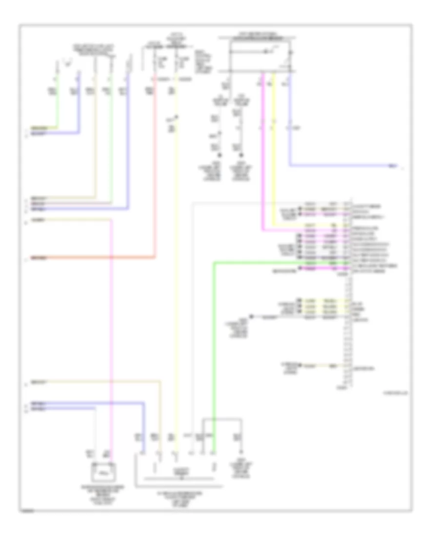
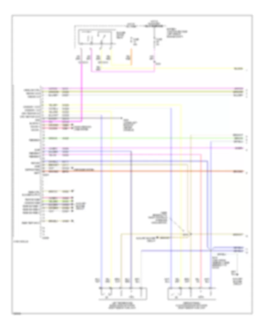
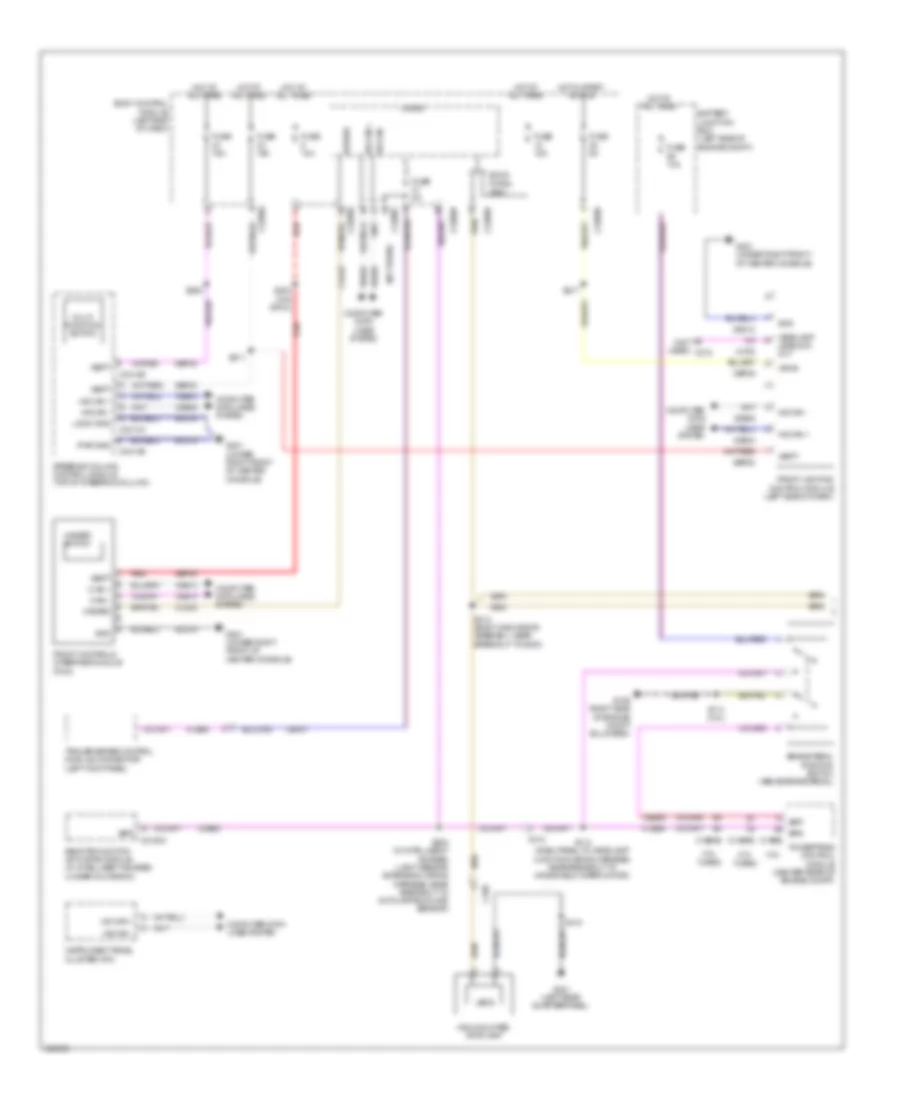
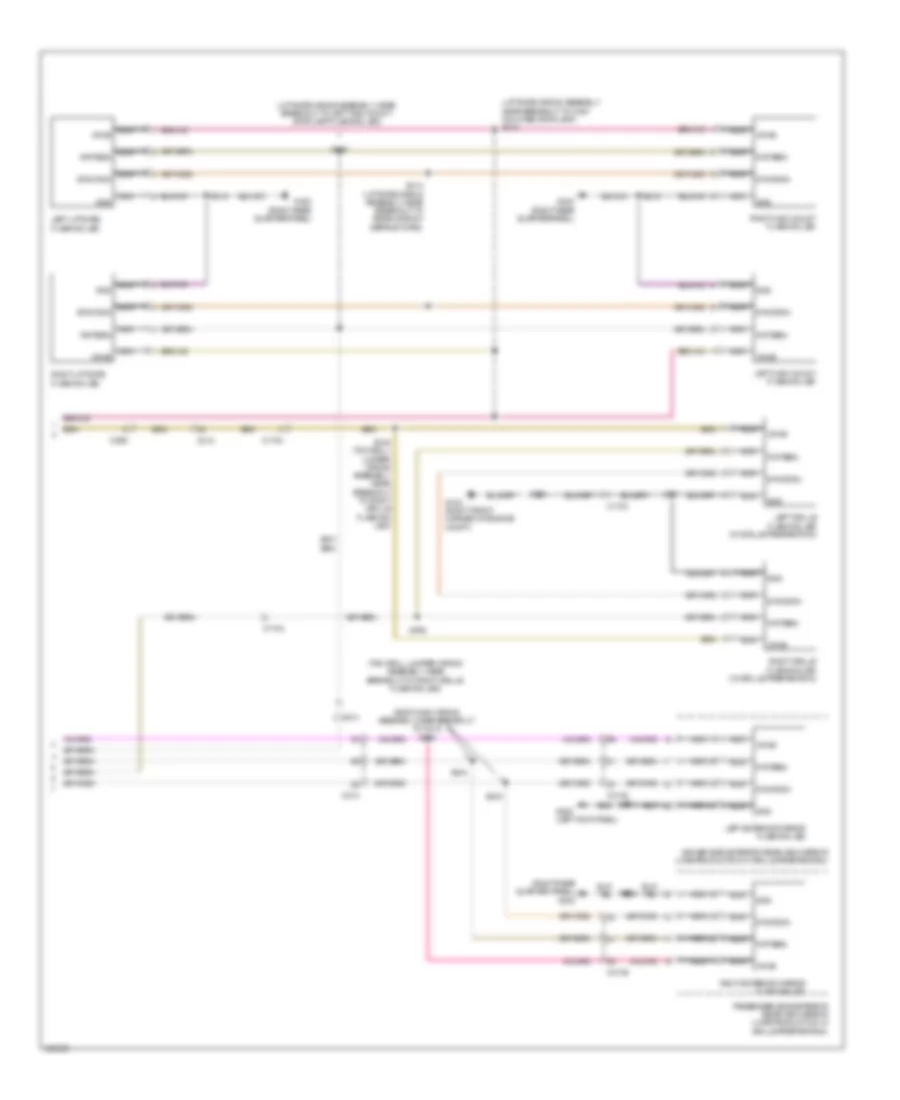
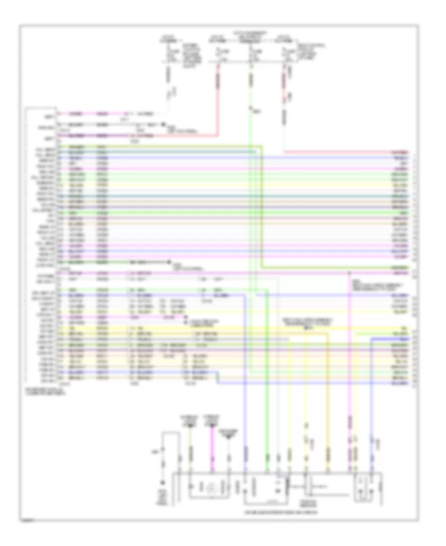
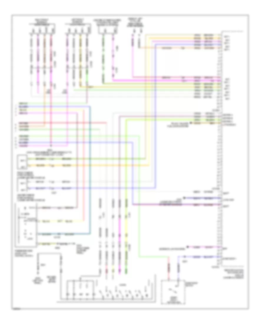
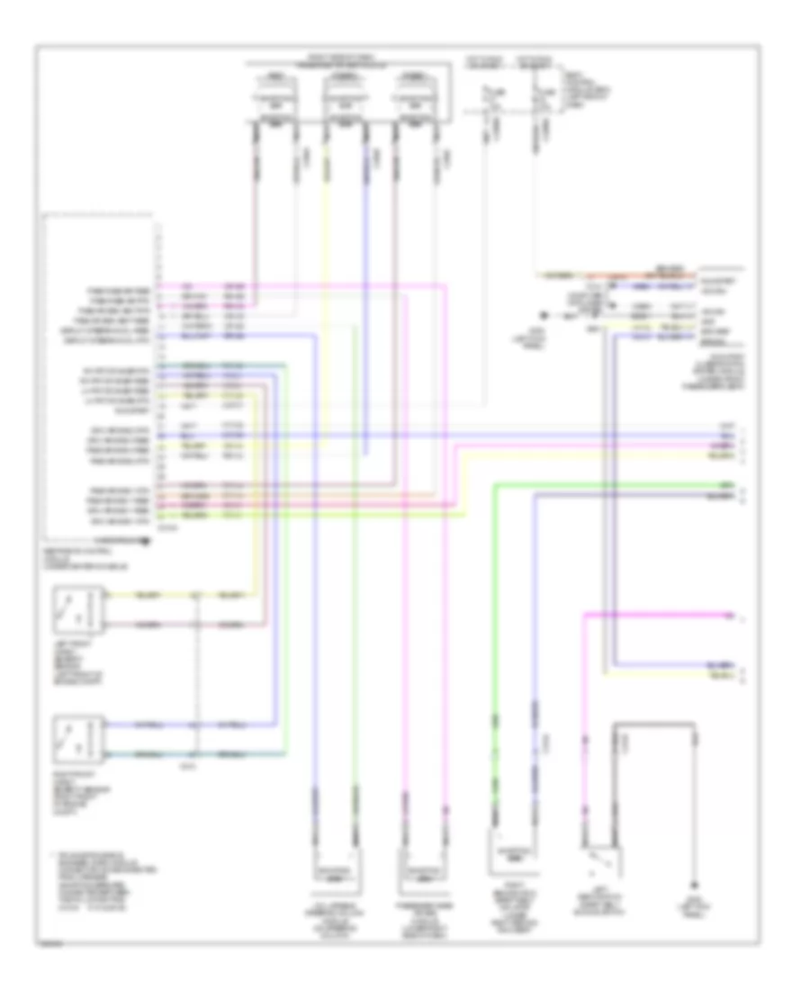
AIR CONDITIONING
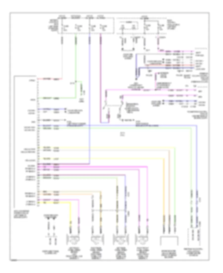
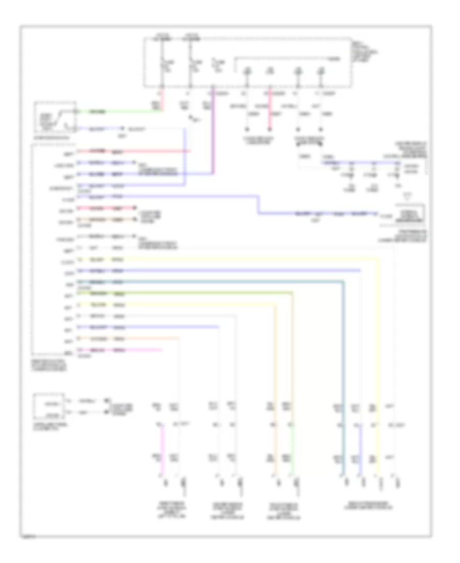
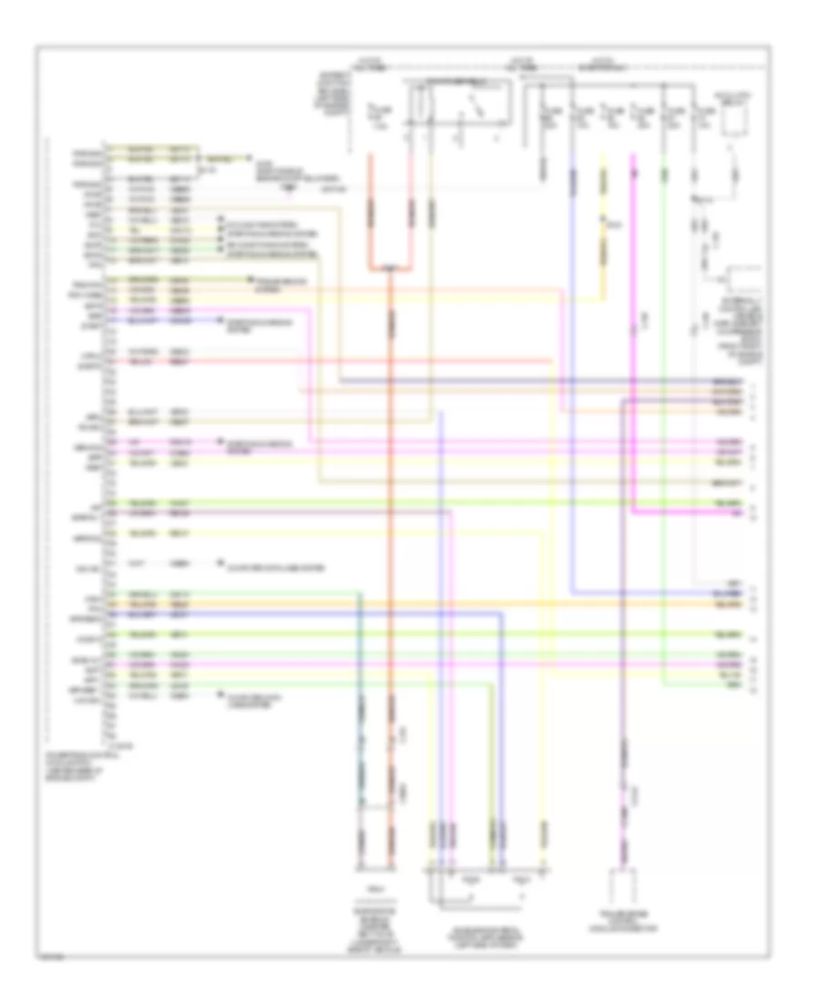
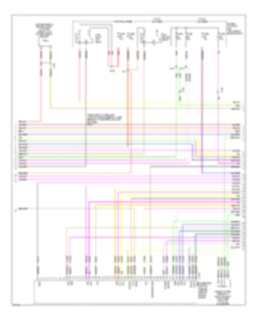
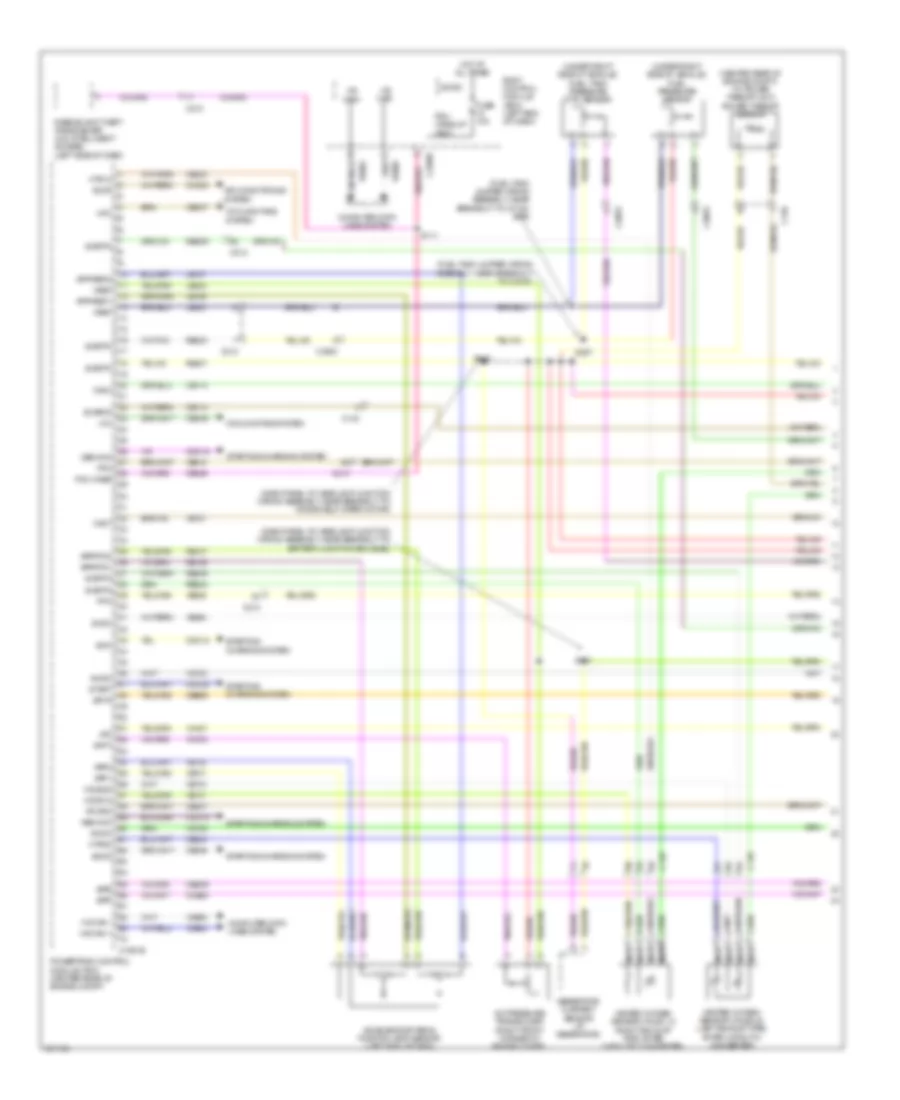
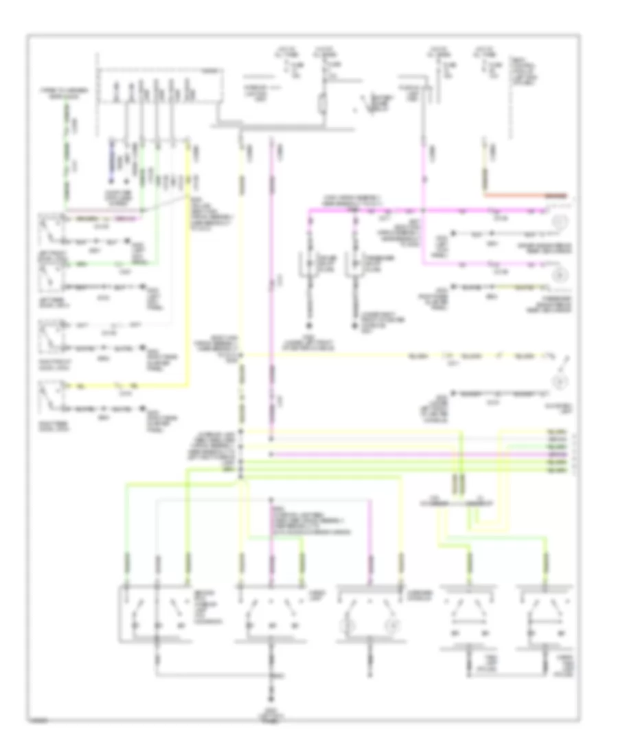
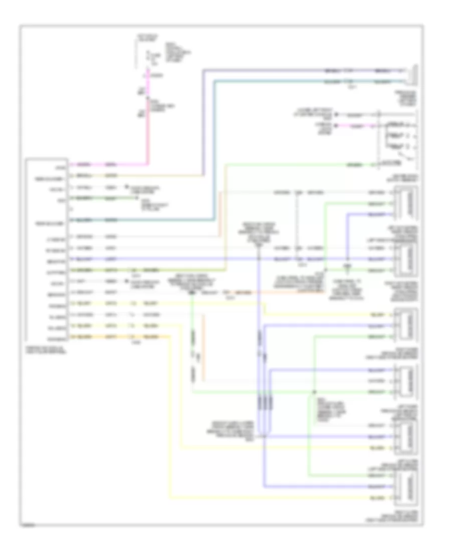
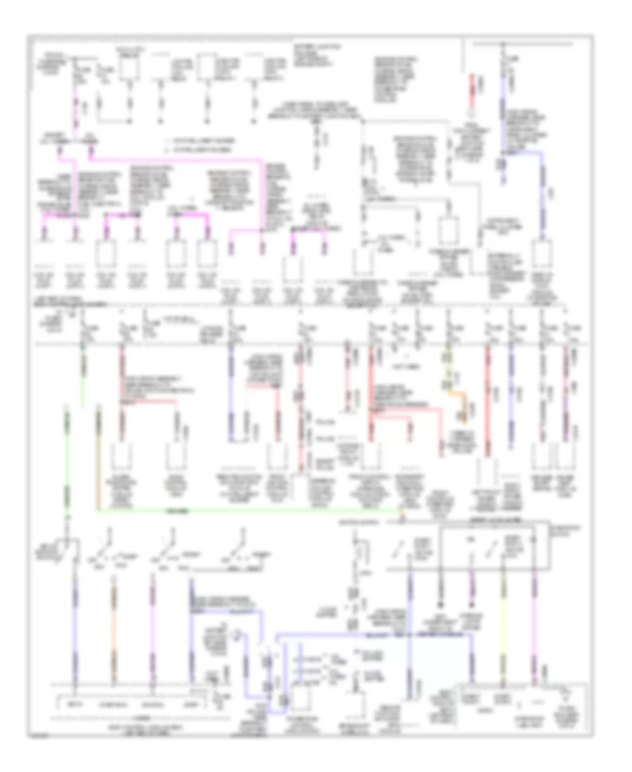
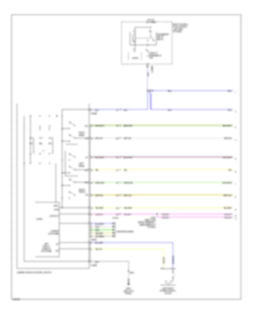
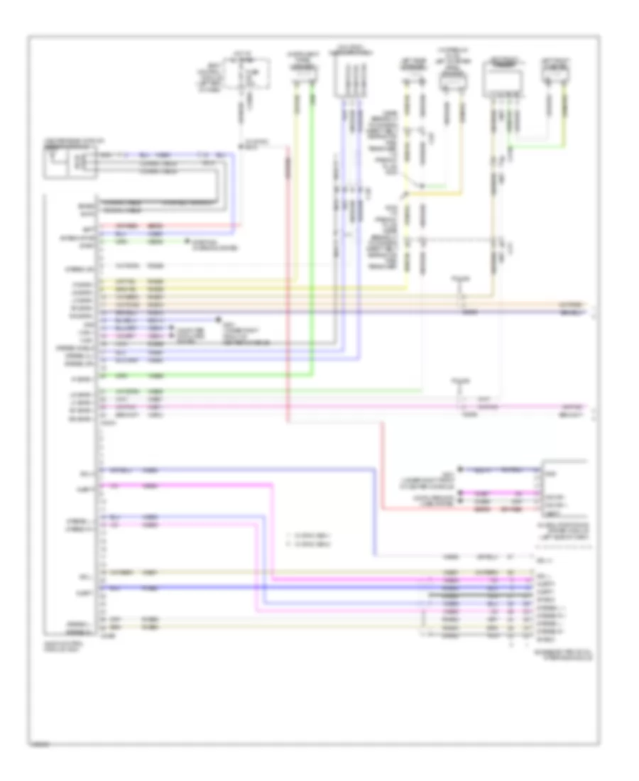
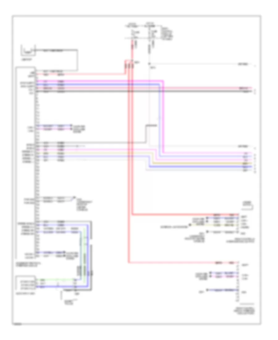
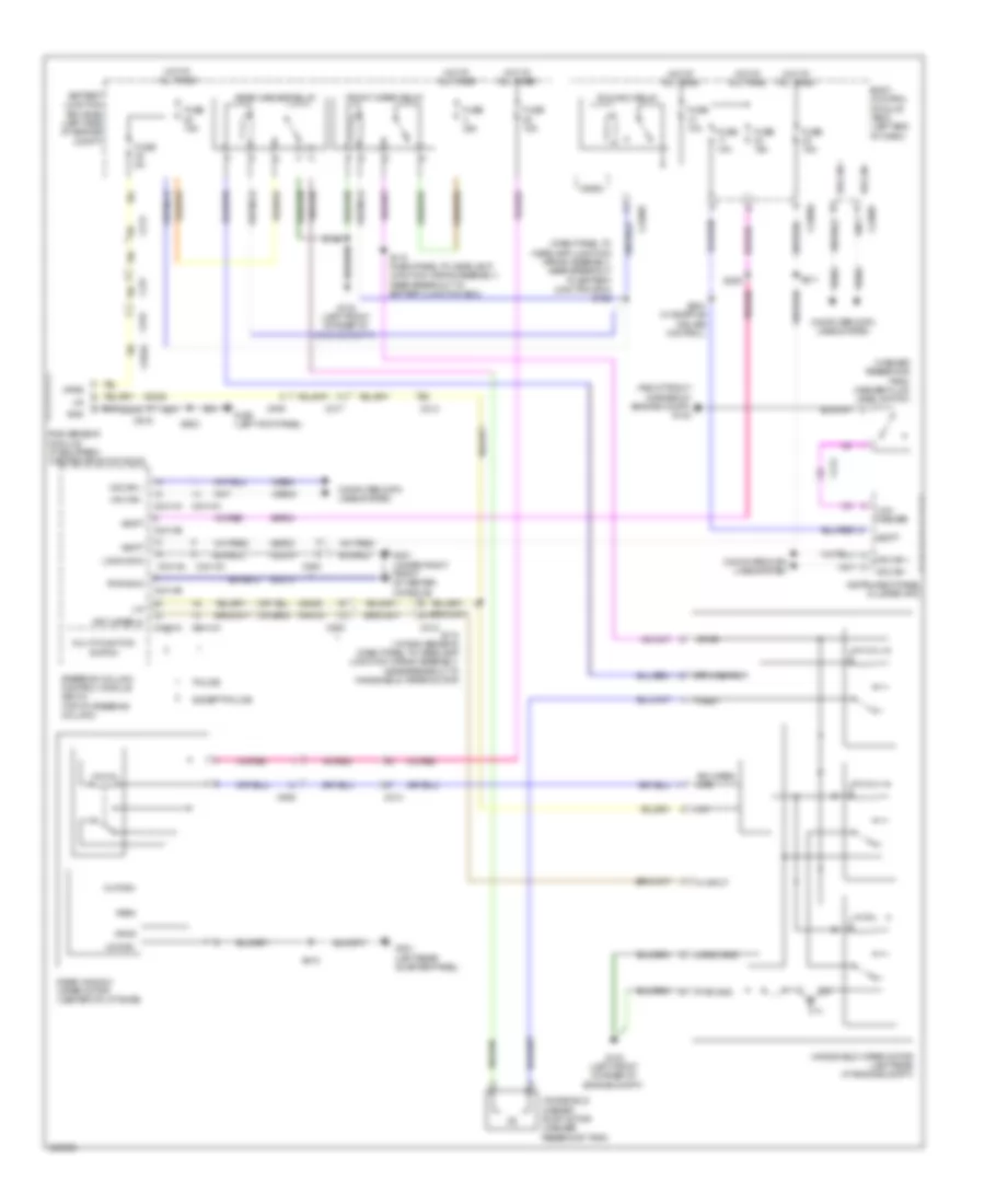
Automatic A/C Wiring Diagram (1 of 4) for Ford Explorer Police Interceptor 2013
 https://portal-diagnostov.com/license.html
Automotive Electricians Portal FZCO
Automotive Electricians Portal FZCO
https://portal-diagnostov.com/license.html
https://portal-diagnostov.com/license.html
Automotive Electricians Portal FZCO
Automotive Electricians Portal FZCO
List of elements for Automatic A/C Wiring Diagram (1 of 4) for Ford Explorer Police Interceptor 2013:
- (center of hvac unit) blower motor speed control
- (front center of hvac unit) blower motor
- (main wiring assembly, near breakout to front controls interface module (fcim))
- (near breakout to blower motor) s229
- Auxiliary blower circuit
- Battery junction box (bjb) (left side of engine compt)
- Blower motor relay
- Blwr rly
- C212
- C228a
- C228b
- C248
- Ch122
- Ch123
- Ch207
- Ch208
- Ch212
- Ch213
- Ch228
- Ch229
- Ch238
- Ch239
- Cha35
- Cha36
- Cha37
- Chs02
- Chs07
- Computer data lines system
- Defogger system
- Defrost req
- Defrost/panel/ floor mode door actuator (right side of hvac unit)
- Driv temp dr ccw
- Driv temp dr cw
- Drv heater feed
- Drv seat
- Evap
- Feedback
- Feedback rear ctrl blower output
- Fuse 30a
- Fuse 40a
- Fuse 5a
- G200 (under left front of center console)
- Gd215
- Gnd
- Hot at all times
- Hot w/ run/start relay energized
- Hvac module
- Left temperature blend door actuator (right side of hvac unit)
- Lh111
- Mode dr 1 ccw
- Mode dr 1 cw
- Mode dr fdbk
- Mot+
- Mot-
- Ms can +
- Ms can -
- Pass heater feed
- Pass seat
- Pass st ntc sense
- Pass temp door ccw
- Pass temp door cw
- Pwm
- Rear sig feed 1
- Rear sig feed 2
- Rear sig feed 3
- Rear temp input
- Recirc ccw
- Recirc cw
- Return
- Rh111
- Right temperature blend door actuator (front center of hvac unit)
- S123
- S213
- S215
- S216 (main wiring assembly, near breakout to c2123)
- Sbb28
- Sbp46
- Seats system
- Temp dr fdbk
- Var blwr ctrl
- Vbatt
- Vdb06
- Vdb07
- Vh101
- Vh406
- Vh436
- Vh438
- Vh440
- Vh441
- Vha09
- Vha18
- Vha25
- Vha39
- Vhs27
- Vref
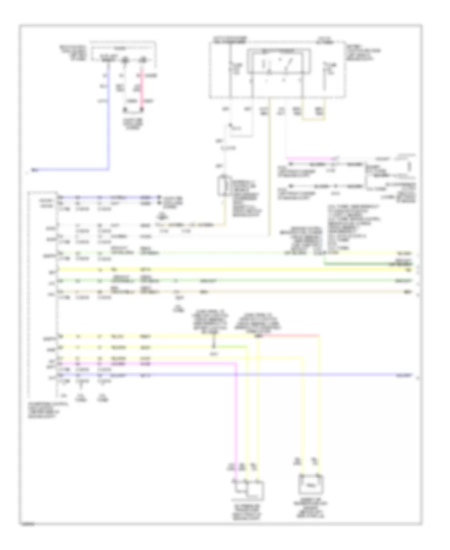
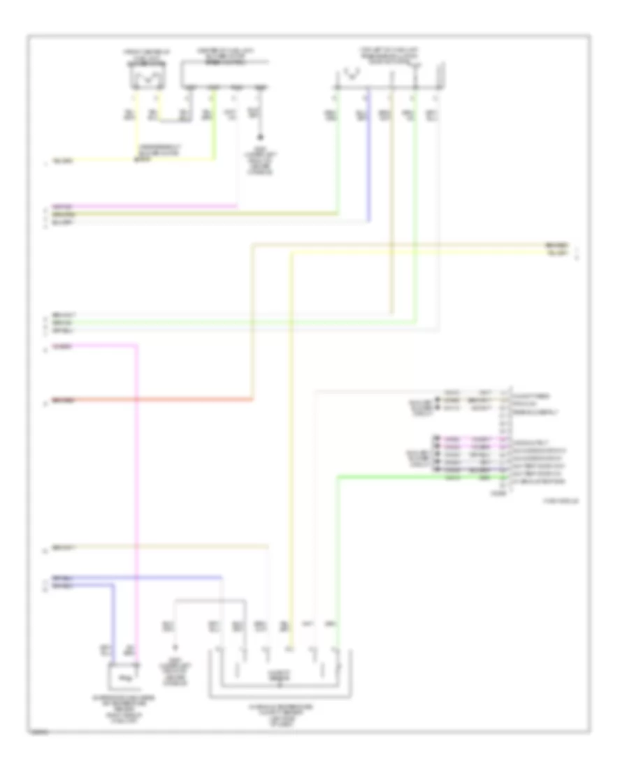
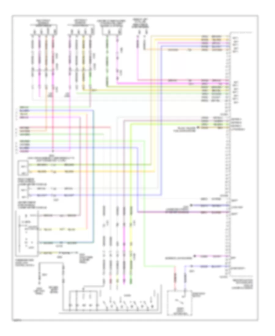
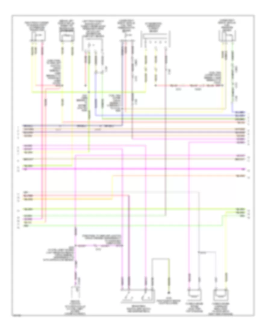
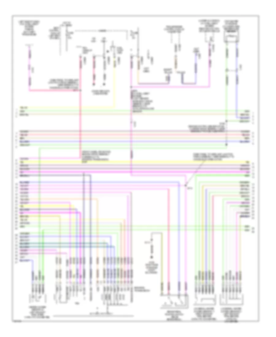
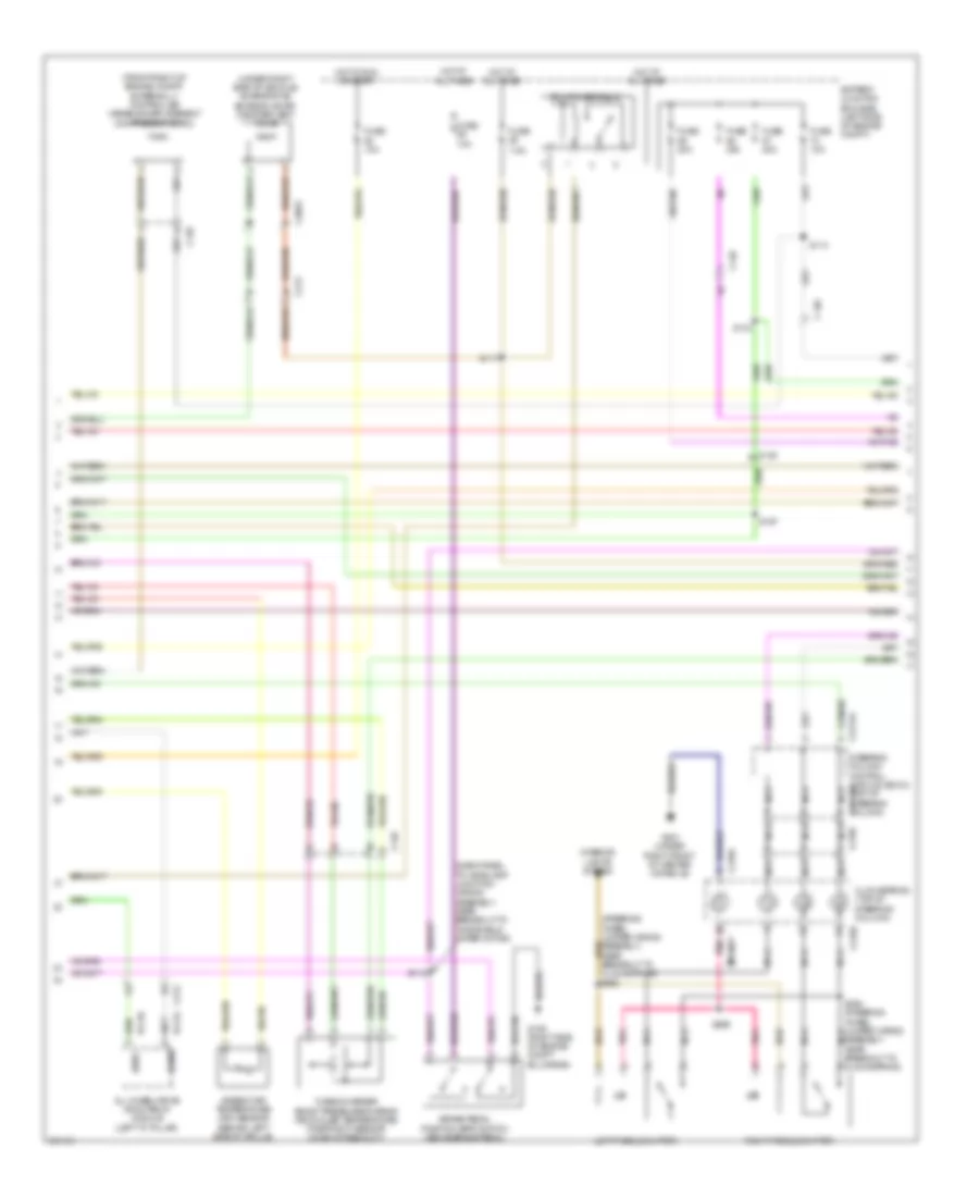
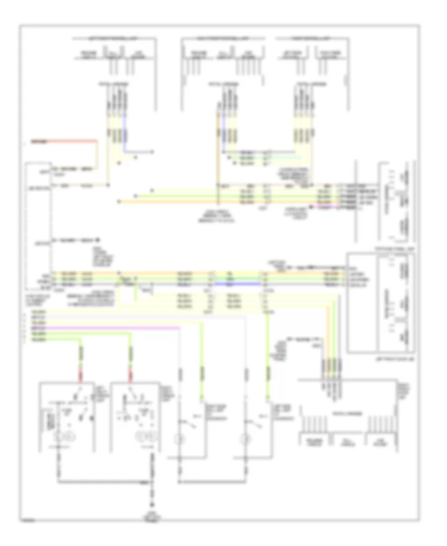
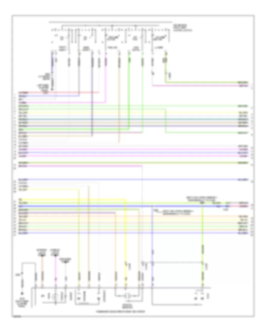
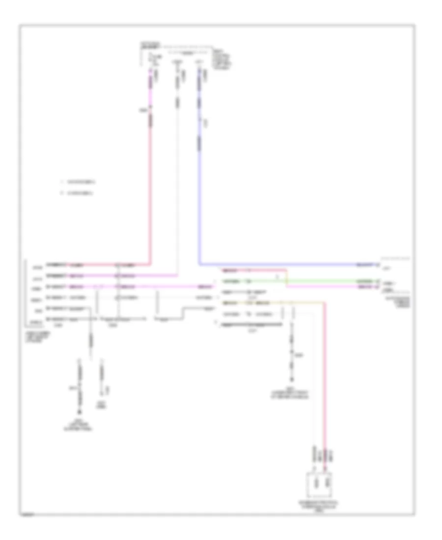
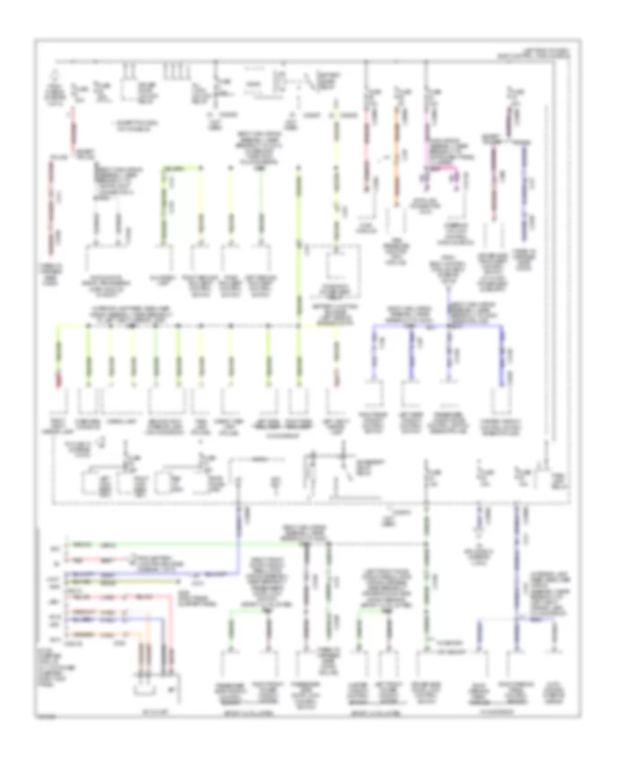
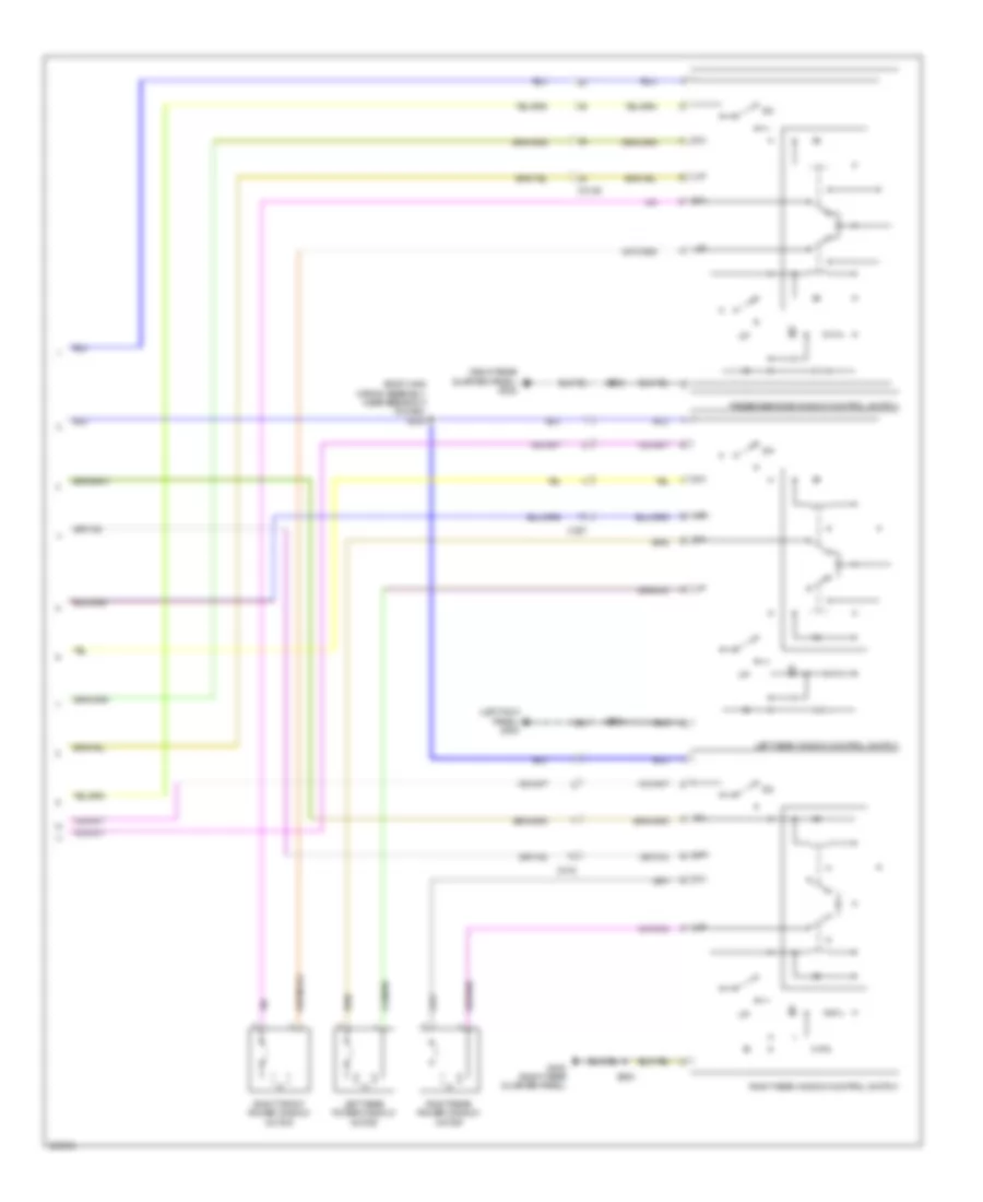
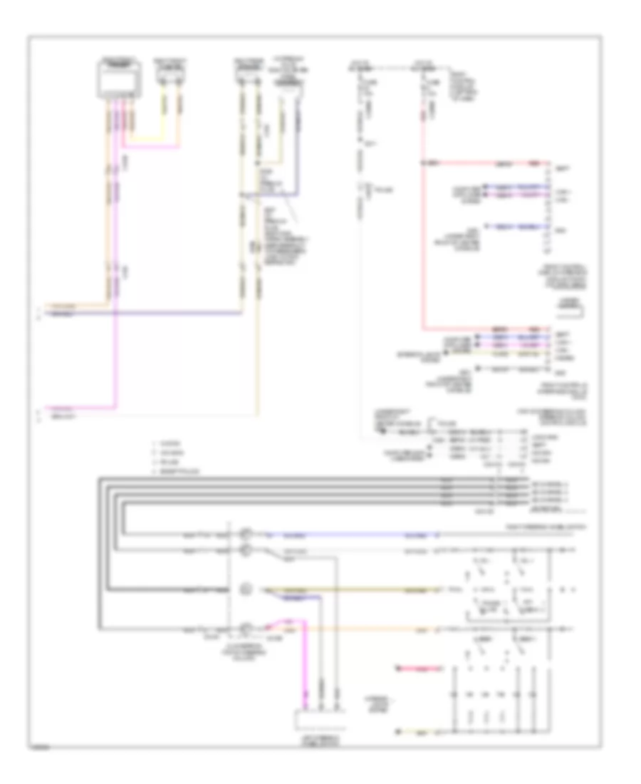
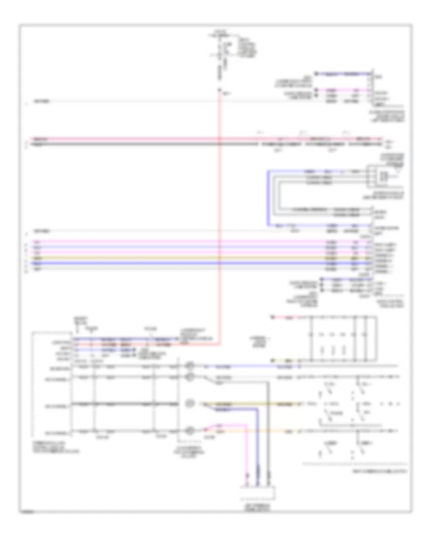
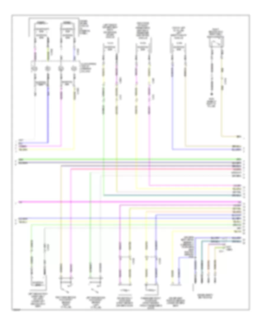
Automatic A/C Wiring Diagram (2 of 4) for Ford Explorer Police Interceptor 2013
List of elements for Automatic A/C Wiring Diagram (2 of 4) for Ford Explorer Police Interceptor 2013:
- (top center of dash) autolamp/sunload sensor
- (top left of hvac unit) fresh/recirculation door actuator
- Aux mode door ccw
- Aux mode door cw
- Aux temp door ccw
- Aux temp door cw
- Auxiliary blower circuit
- Body control module (bcm) (left end of dash)
- C2280a
- C2280b
- C228b
- C228c
- C291
- Ch112
- Ch242
- Ch243
- Ch244
- Ch245
- Cha05
- Dr sunload
- Drv st ntc sense
- Evaporator discharge air temperature sensor (right side of hvac unit)
- Fuse 10a
- Fuse 5a
- G200 (under left front of center console)
- Gd215
- Green
- Hot at all times
- Hot w/ run/start relay energized
- Humidity sense
- Humidity sensor
- Hvac module
- In vehicle sig temp sens
- In-vehicle temperature/ humidity sensor (left side of dash)
- Interior lights system
- Led gnd
- Led return
- Mode output
- Pass sunload
- Pwm com
- Rear blower rly
- Red
- Rln44
- S200
- S217
- Seats system
- Vh413
- Vh414
- Vh416
- Vh417
- Vha38
- Vhs26
- Vln48
- Vln49
- Vln50
- W/ adaptive cruise
- W/o adaptive cruise
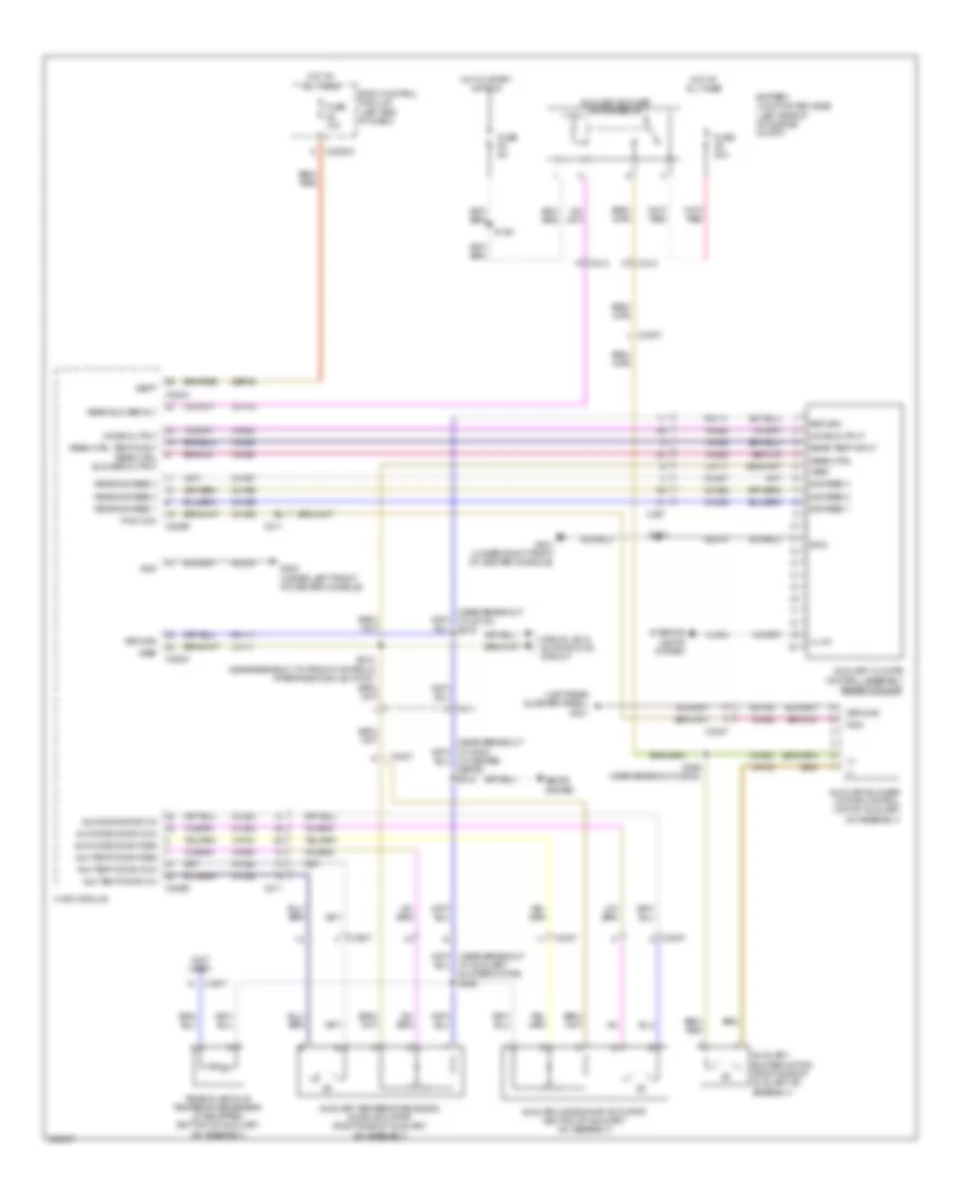
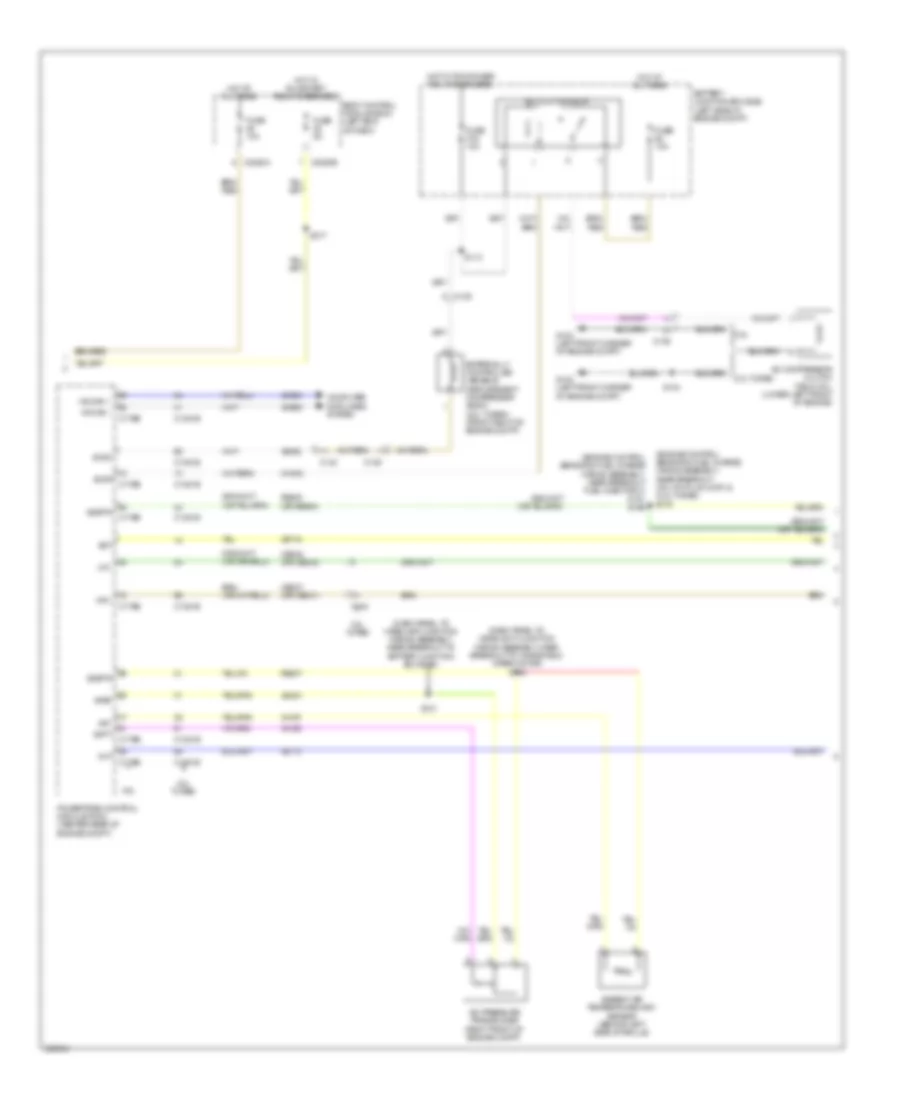
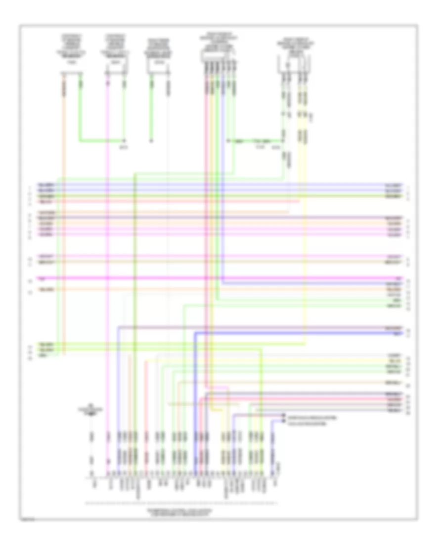
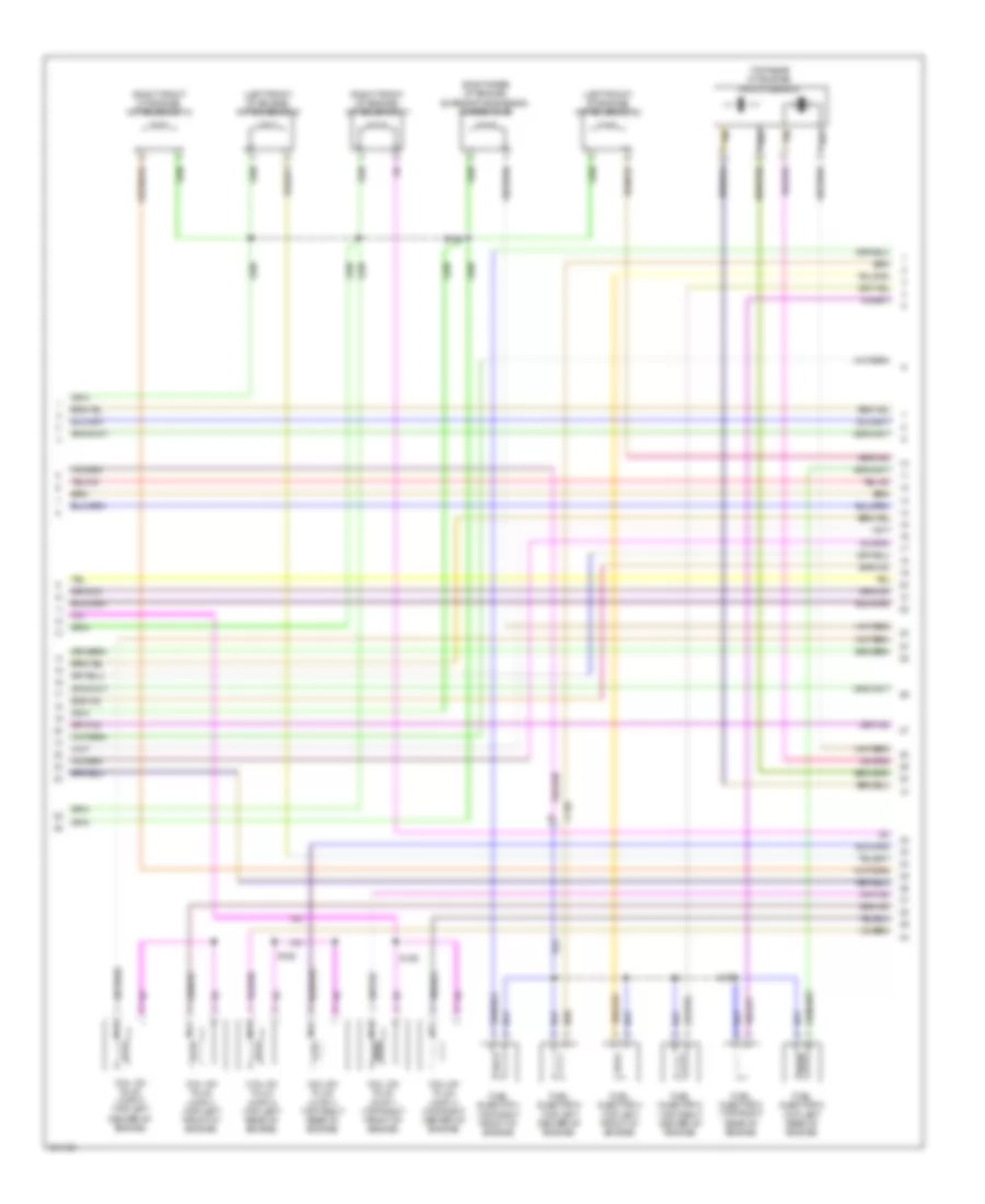
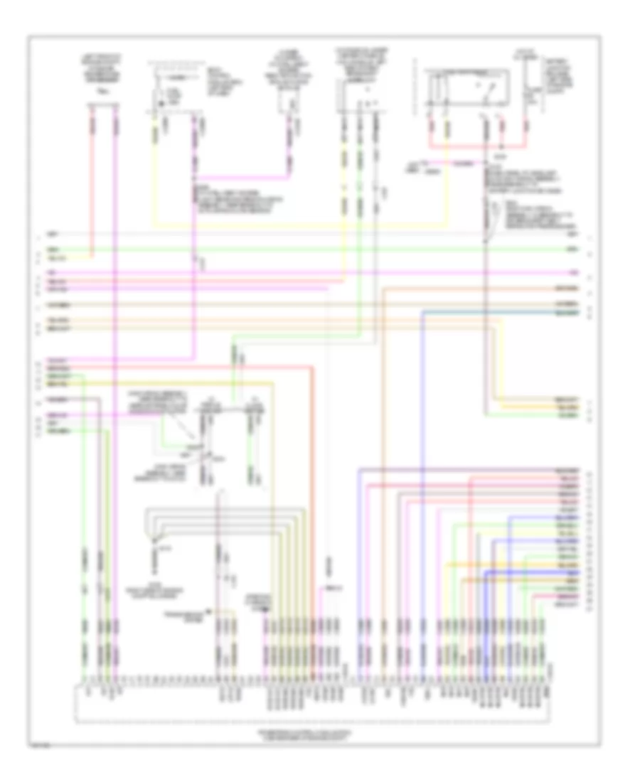
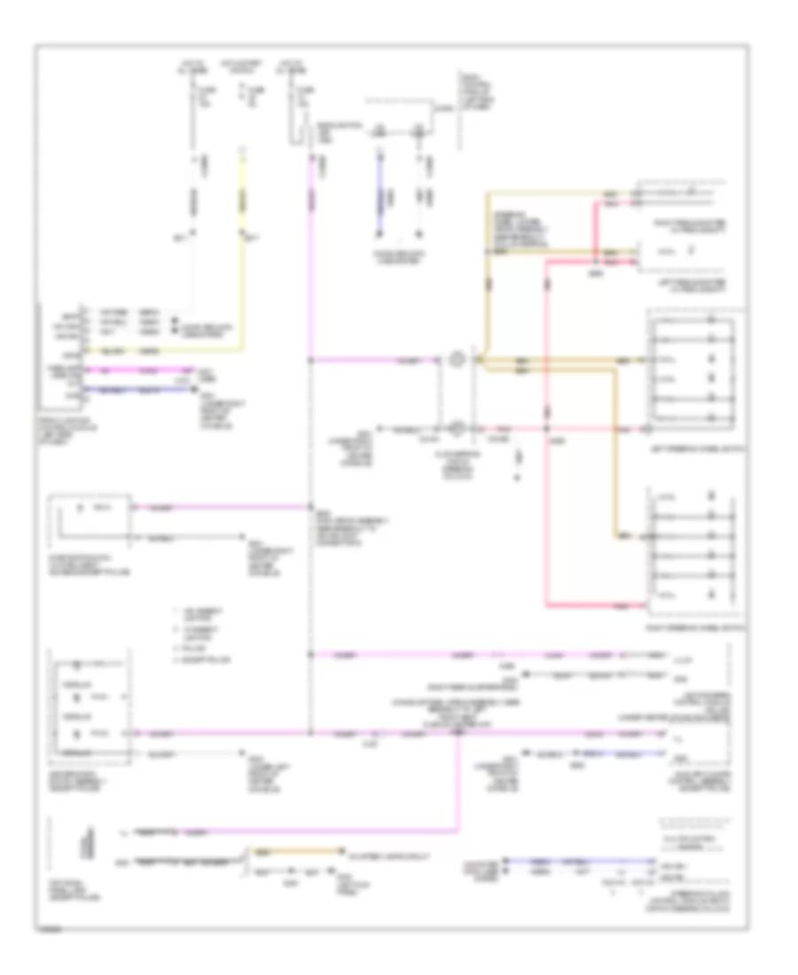
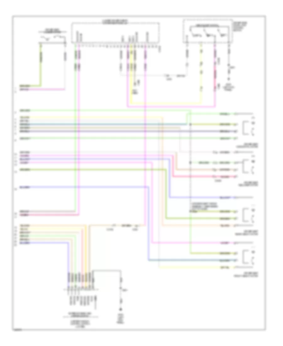
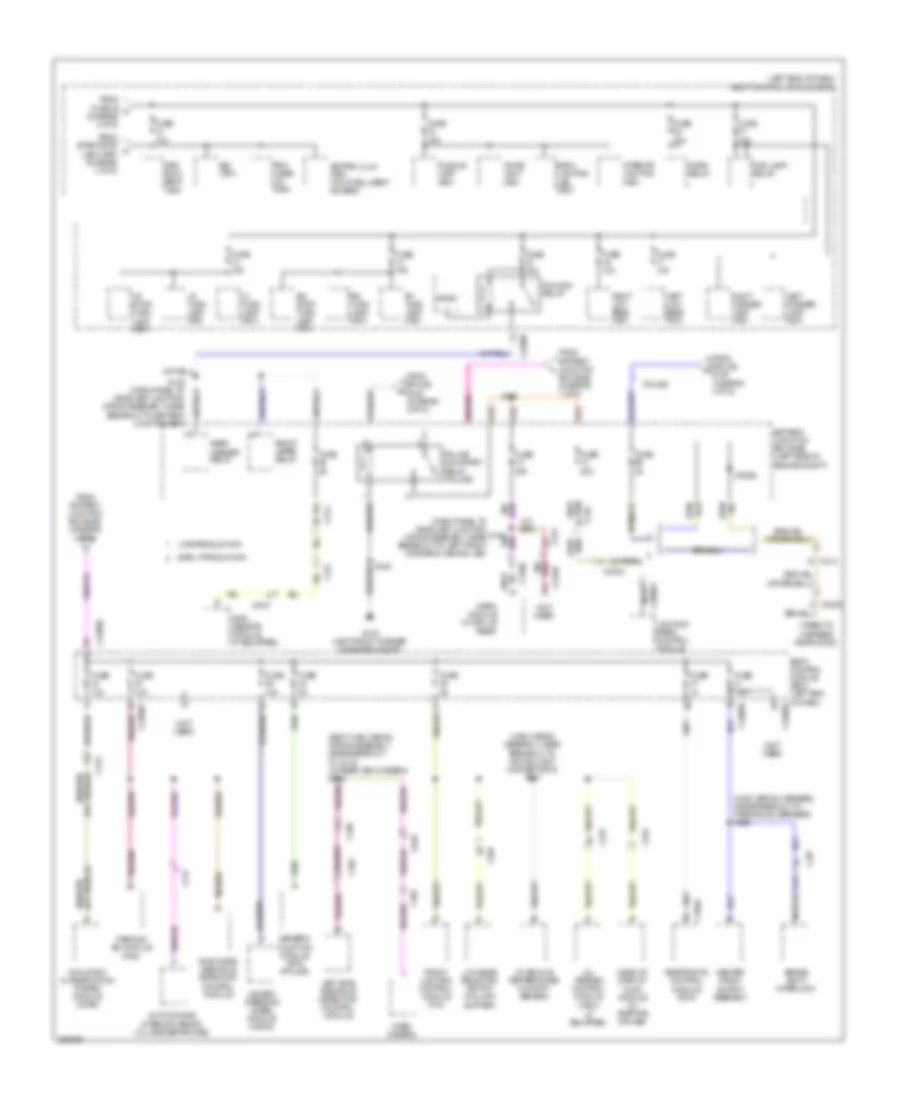
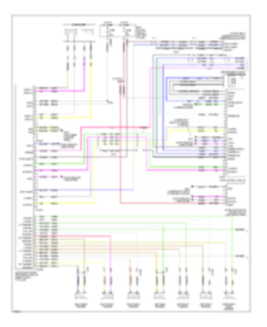
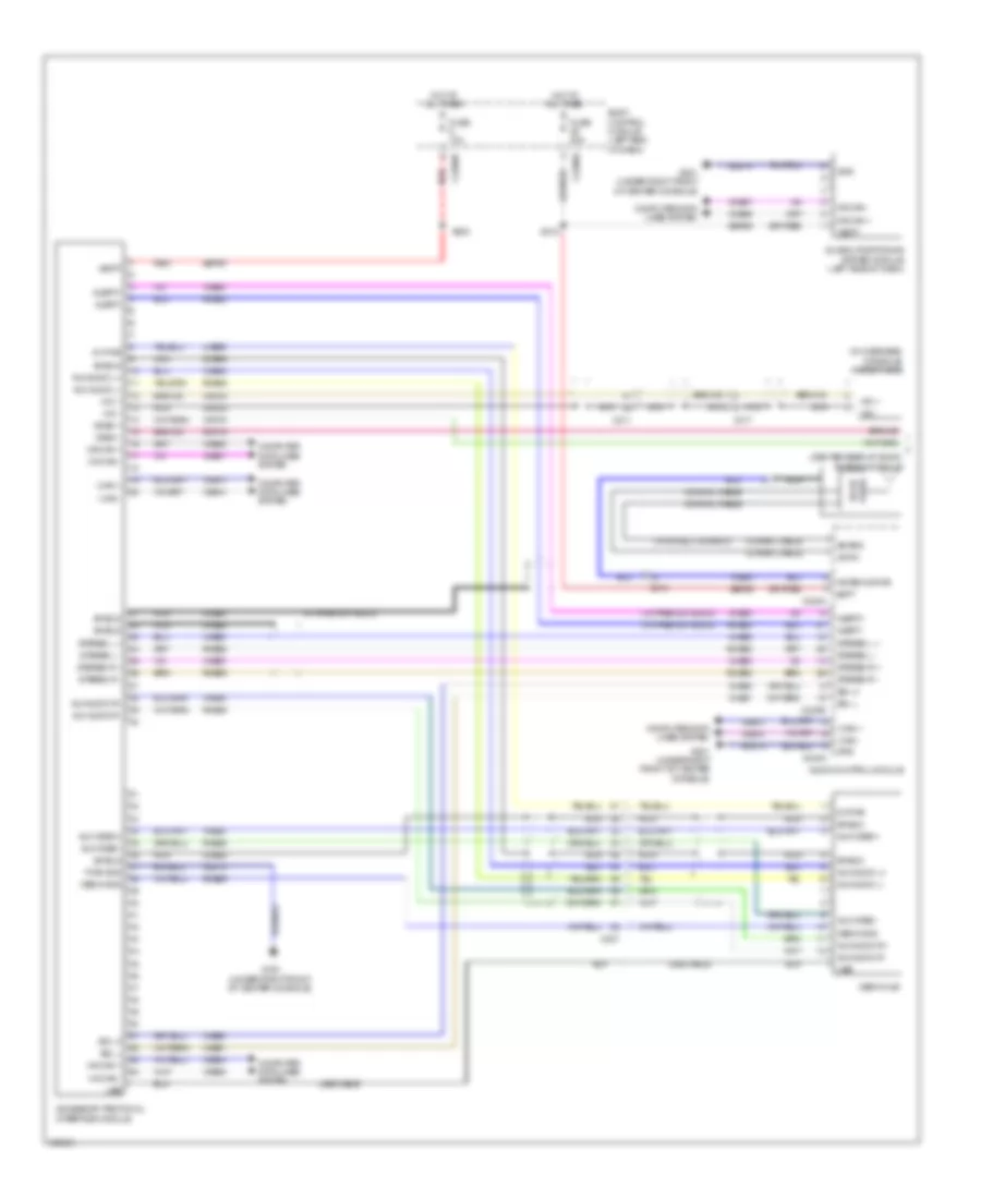
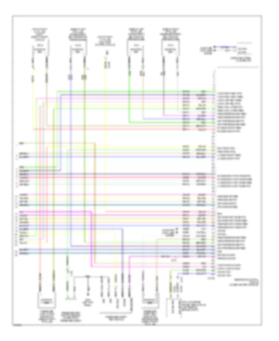
Automatic A/C Wiring Diagram (3 of 4) for Ford Explorer Police Interceptor 2013
List of elements for Automatic A/C Wiring Diagram (3 of 4) for Ford Explorer Police Interceptor 2013:
- (3.5l turbo: near breakout to camshaft position 11 (cmp11) sensor) (2.0l turbo: engine control sensor & fuel charge wiring assembly, near breakout coil on plug (cop) 2) (2.0l turbo) s176 (3.5l turbo) s1006
- (dash panel to headlamp junction wiring assembly, near breakout to battery junction box (bjb))
- (dash panel to headlight junction wiring assembly, near breakout to windshield wiper motor) s143
- (engine control sensor & fuel charge wiring assembly, near breakout fuel injector 3) (3.5l) s156
- 2.0l turbo
- 3.5l
- 3.5l turbo
- A/c clutch relay
- A/c compressor clutch field coil (lower left front of engine)
- A/c pressure transducer (right front of engine compt)
- Aat
- Accr
- Acpt
- Ambient air temperature (aat) sensor (behind left side of grille)
- Autolamp sens in
- Battery junction box (bjb) (left side of engine compt)
- Body control module (bcm) (left end of dash)
- C1381b
- C1381e
- C139
- C140
- C1551b
- C1551e
- C175b
- C175e
- C2280b
- Cec07 (or cec01)
- Cec08 (or cec02)
- Ch302
- Cht
- Computer data lines system
- Ect
- Evdc
- Except 2.0l turbo
- Externally controlled variable displacement compressor (evdc) (except 3.5l) (front right of engine compt)
- Fuse 10a
- Fuse 70a 10a
- G103 (left front corner of engine compt)
- Hfc
- Hot at all times
- Hot w/ pcm power relay energized
- Hs can +
- Hs can -
- Le424
- Lfc
- Micro
- Ms can+
- Ms can-
- Powertrain control module (pcm) (center rear of engine compt)
- Re405 (or re454)
- Re407
- S104
- S113
- S121
- Sigrtn
- Vdb04
- Vdb05
- Vdb06
- Vdb07
- Ve462
- Ve712
- Ve716
- Vh407
- Vh433
- Vlf14
- Vref
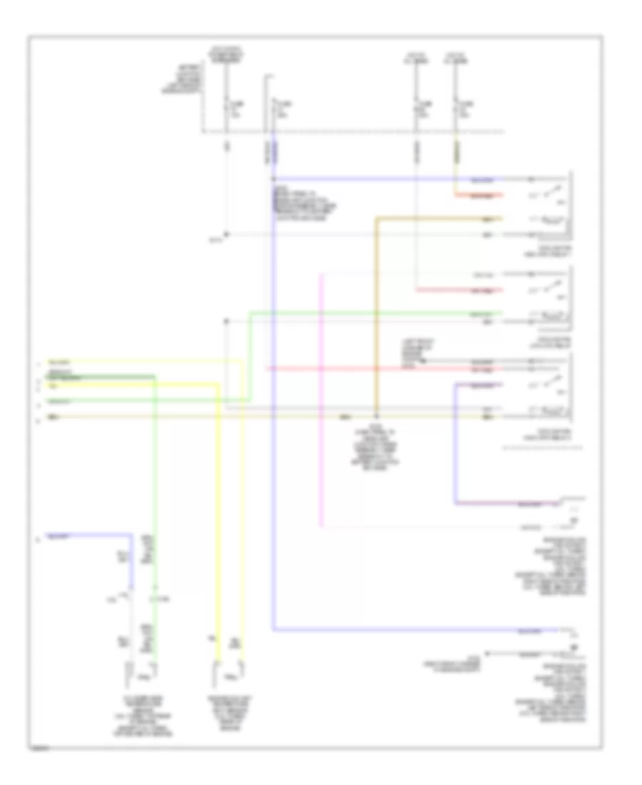
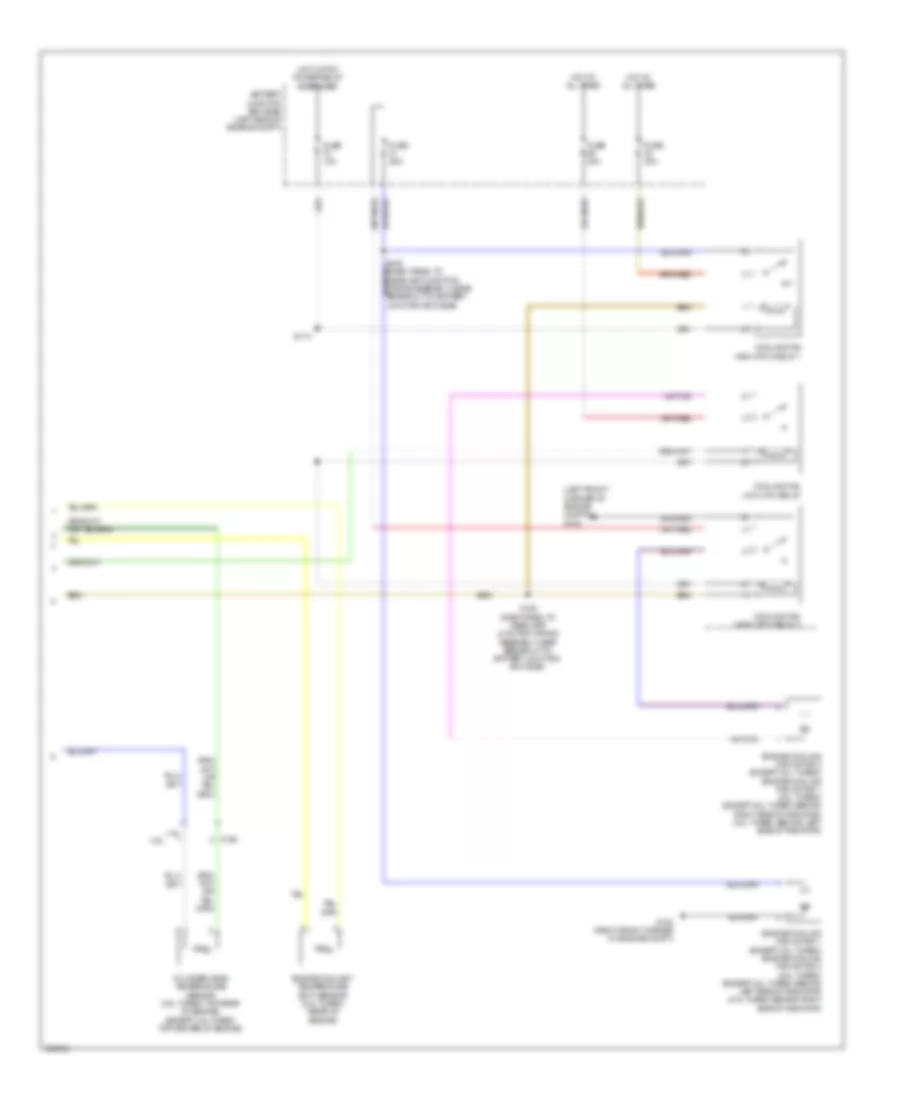
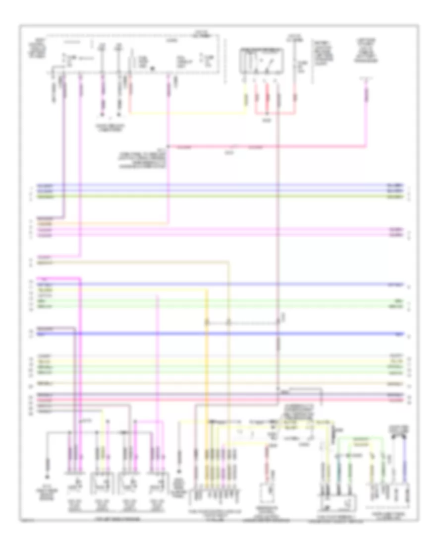
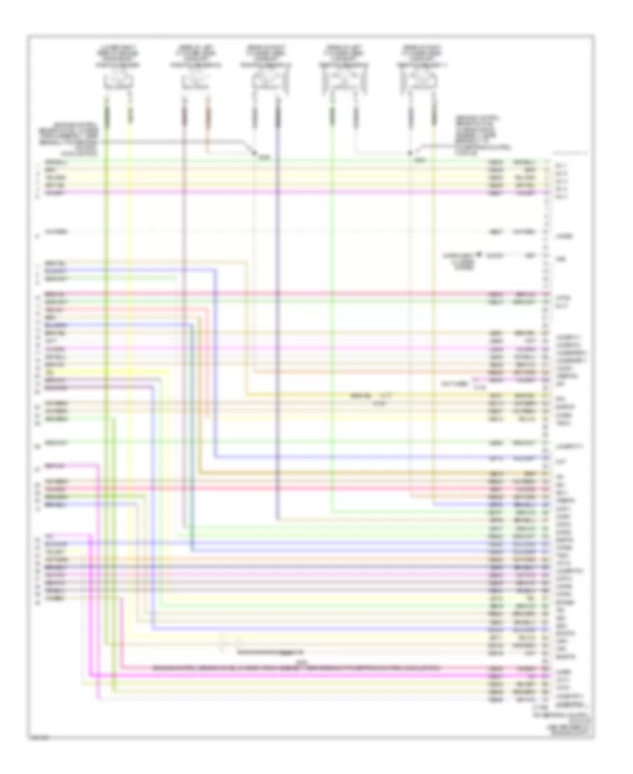
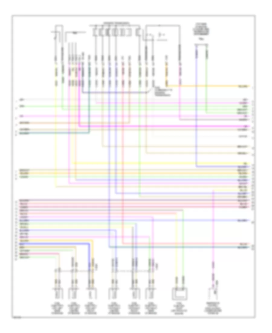
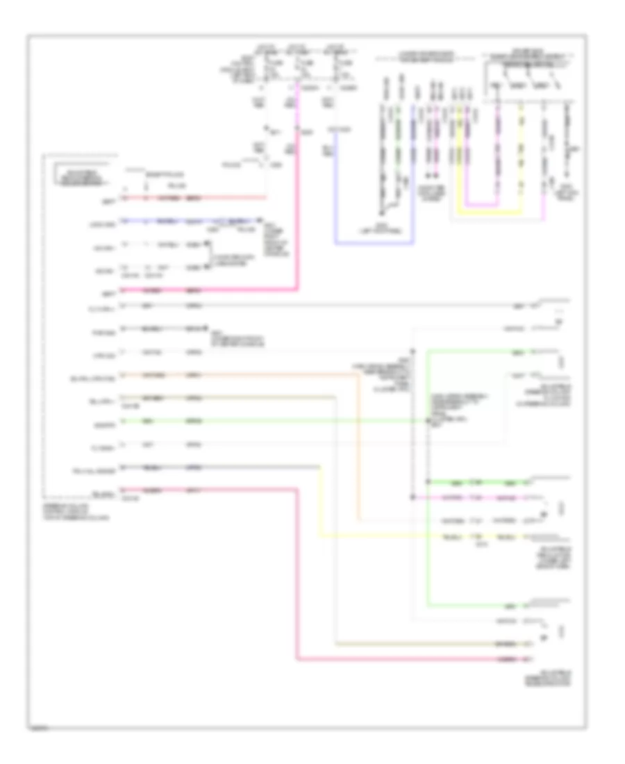
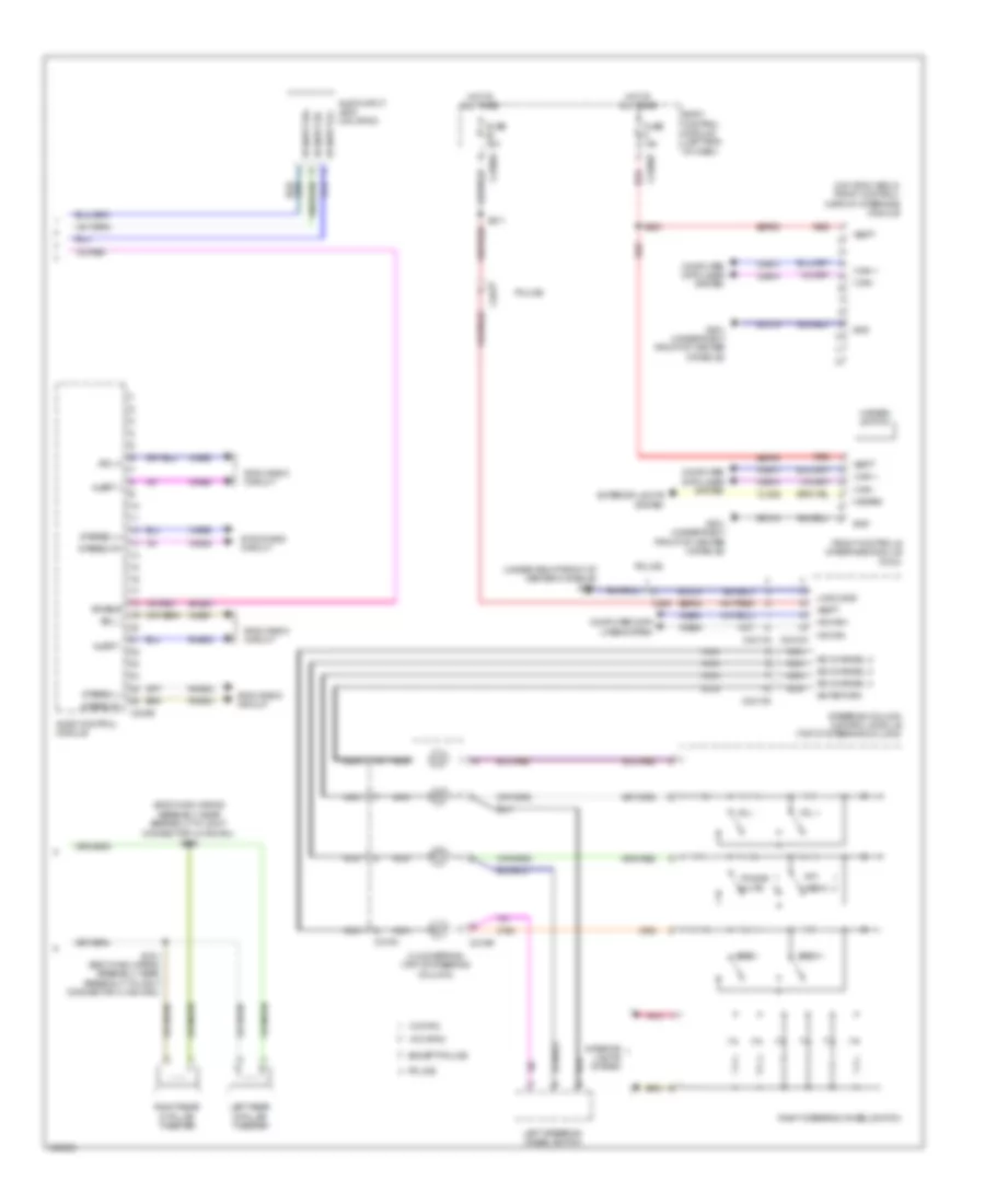
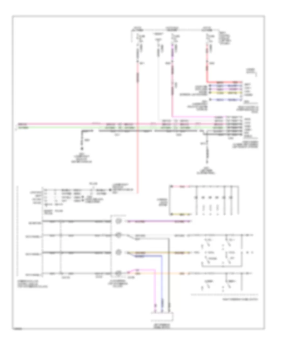
Automatic A/C Wiring Diagram (4 of 4) for Ford Explorer Police Interceptor 2013
List of elements for Automatic A/C Wiring Diagram (4 of 4) for Ford Explorer Police Interceptor 2013:
- (left front corner of engine compt) g103
- 3.5l
- Battery junction box (bjb) (left side of engine compt)
- C192
- Cooling fan high (hfc) relay 1
- Cooling fan high (hfc) relay 2
- Cooling fan low (lfc) relay
- Cylinder head temperature sensor (3.5l turbo: top rear of engine) (except 3.5l turbo: top center of engine)
- Engine coolant temperature (ect) sensor (2.0l turbo) (rear of engine)
- Engine cooling fan motor 1 (except 2.0l turbo) engine cooling fan motor 2 (2.0l turbo) (except 2.0l turbo: behind left side of radiator) (2.0l turbo: behind right side of radiator)
- Engine cooling fan motor 2 (except 2.0l turbo) engine cooling fan motor 1 (2.0l turbo) (except 2.0l turbo: behind right side of radiator) (2.0l turbo: behind left side of radiator)
- Fuse 10a
- Fuse 25a
- Fuse 40a
- G102 (right front corner of engine compt)
- Hot at all times
- Hot w/ pcm power relay energized
- S113
- S182 (dash panel to headlamp junction wiring assembly, near breakout to battery junction box (bjb))
Auxiliary Blower Wiring Diagram for Ford Explorer Police Interceptor 2013
List of elements for Auxiliary Blower Wiring Diagram for Ford Explorer Police Interceptor 2013:
- (+)
- (-)
- (left rear quarter panel) g301
- (near breakout to auxiliary blower motor) s385
- (near breakout to c2123) s216
- (near breakout to g300) (w/ heated seats) s313
- (not used)
- Aux mode door ccw
- Aux mode door cw
- Aux mode door fdbk
- Aux temp door ccw
- Aux temp door cw
- Aux temp door fdbk
- Auxiliary blower motor (right side of auxiliary a/c assembly)
- Auxiliary blower motor control (top of auxiliary a/c assembly)
- Auxiliary blower motor relay
- Auxiliary climate control assembly (except police)
- Auxiliary mode door actuator (bottom of auxiliary a/c assembly)
- Auxiliary temperature blend door actuator (right side of auxiliary a/c assembly)
- Battery junction box (bjb) (left side of of engine compt)
- Body control module (left end of dash)
- C211
- C212
- C213
- C2280a
- C228a
- C228b
- C237
- C3007
- Ch112
- Ch242
- Ch243
- Ch244
- Ch245
- Cha02
- Cha05
- Cha35
- Cha36
- Cha37
- Fuse 10a
- Fuse 40a
- Fuse 5a
- G200 (under left front of center console)
- G201 (under right front of center console)
- Gd149
- Gd214
- Gd215
- Gnd
- Ground
- Hot at all times
- Hot in start or run
- Hvac module
- Illum
- Interior lights system
- Lh111
- Manual a/c & automatic a/c circuit
- Mode output
- Pwm
- Pwm com
- Rear blower rly
- Rear ctrl
- Rear ctrl temp input rear ctrl blower output
- Rear in-vehicle temperature sensor (if equipped) (bottom of auxiliary a/c assembly)
- Rear sig feed 1
- Rear sig feed 2
- Rear sig feed 3
- Rear temp input
- Return
- Rh111
- S125
- S215 (near breakout to front controls interface module (fcim))
- S386 (near breakout c3002)
- S392
- Sbp46
- Seats system
- Sig feed 1
- Sig feed 2
- Sig feed 3
- Vbatt
- Vha09
- Vha18
- Vha19
- Vha25
- Vha38
- Vha39
- Vln04
- Vref
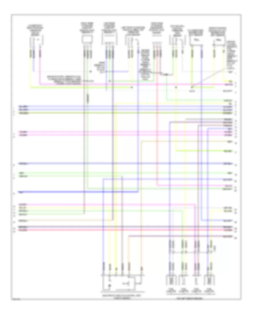
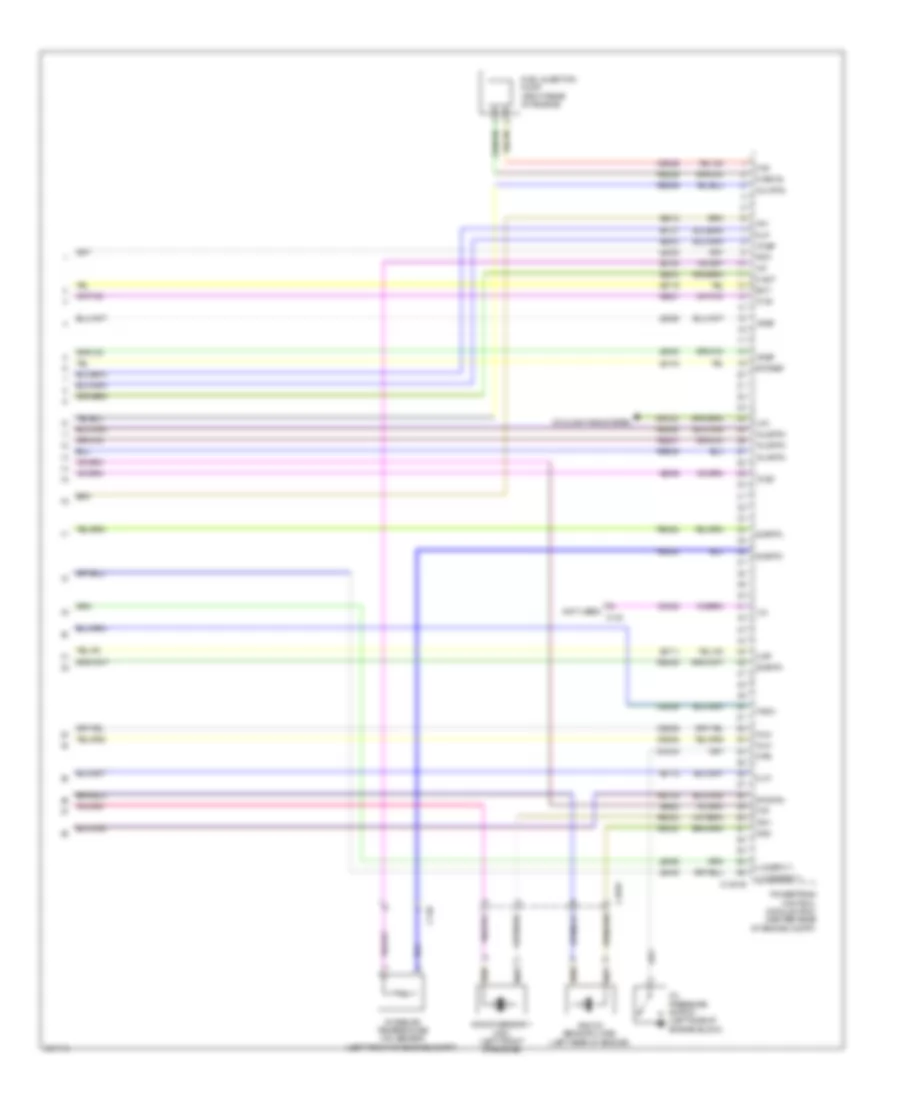
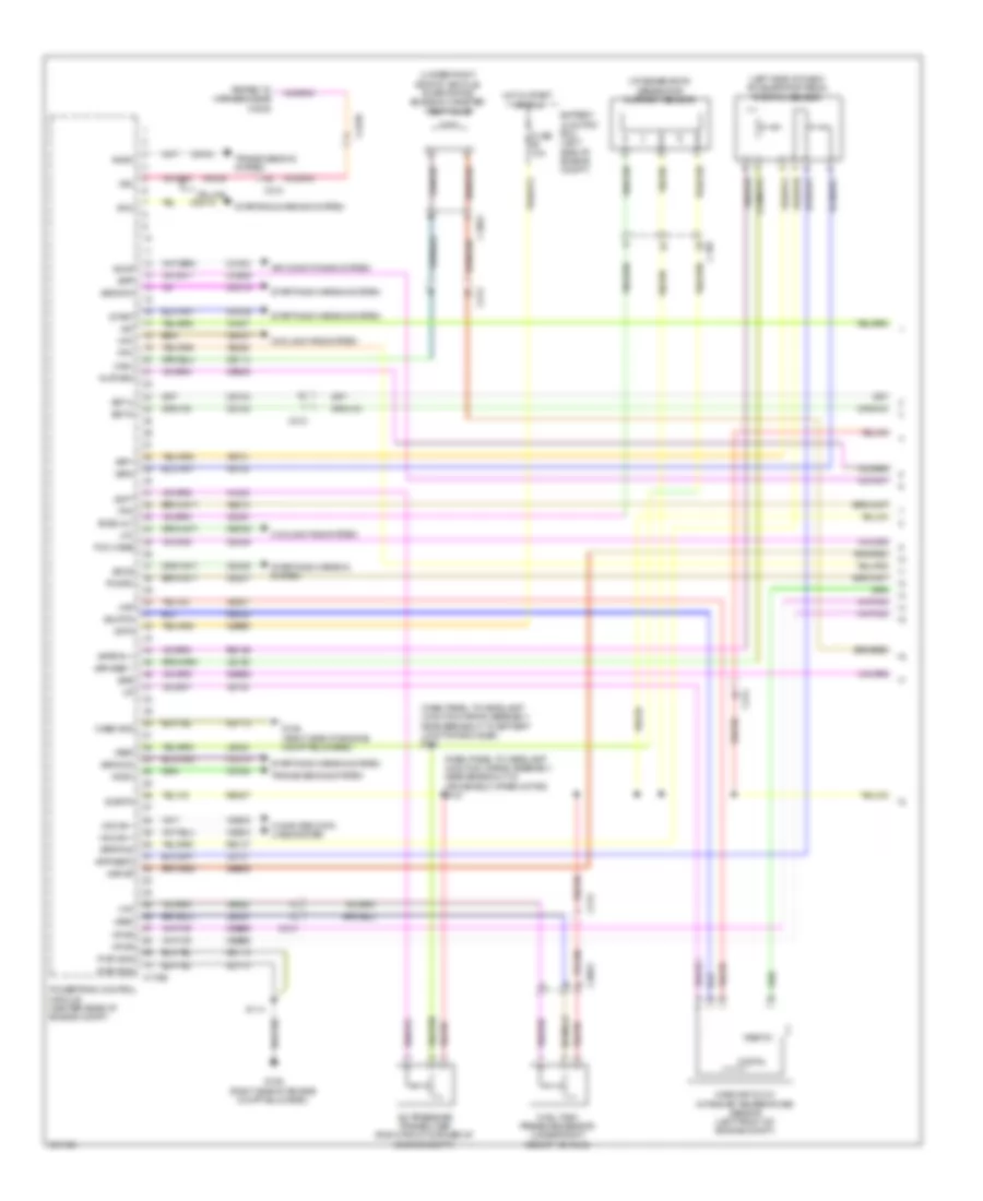
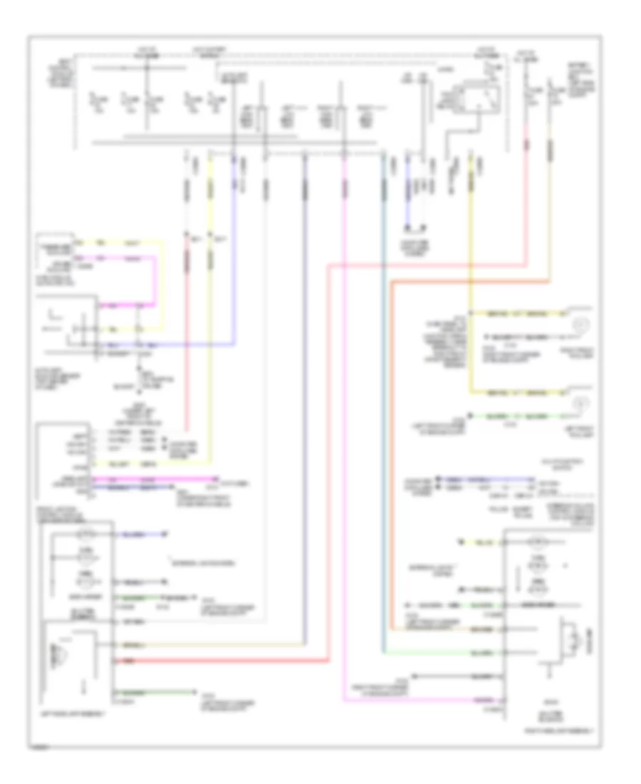
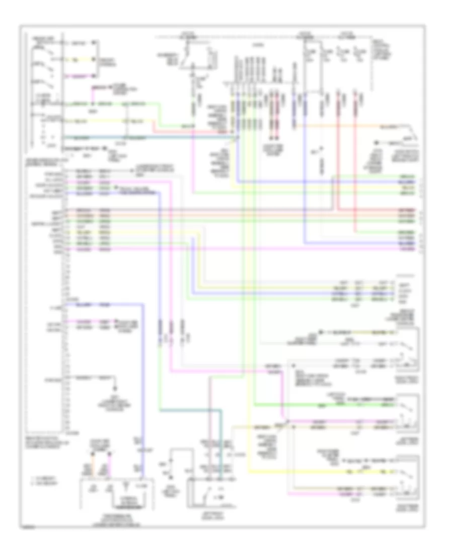
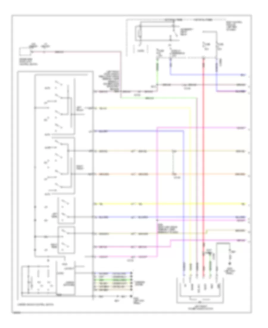
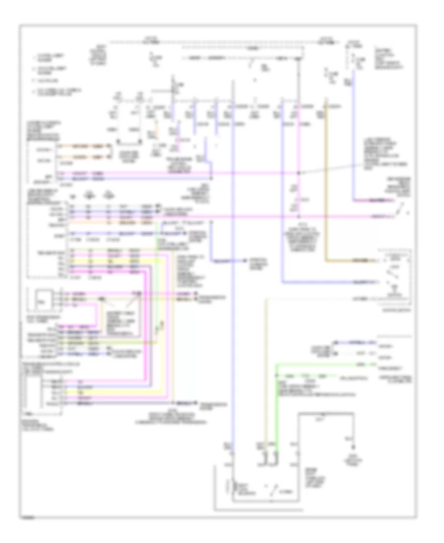
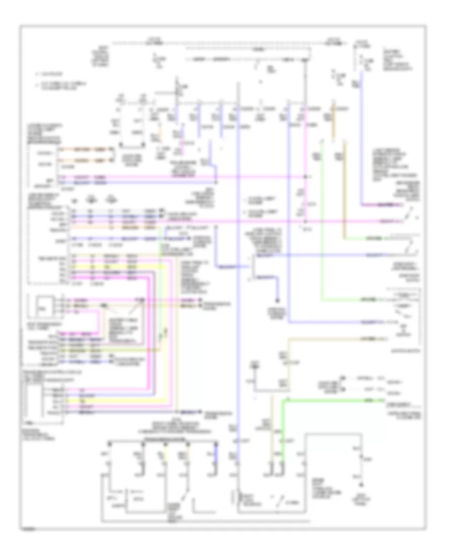
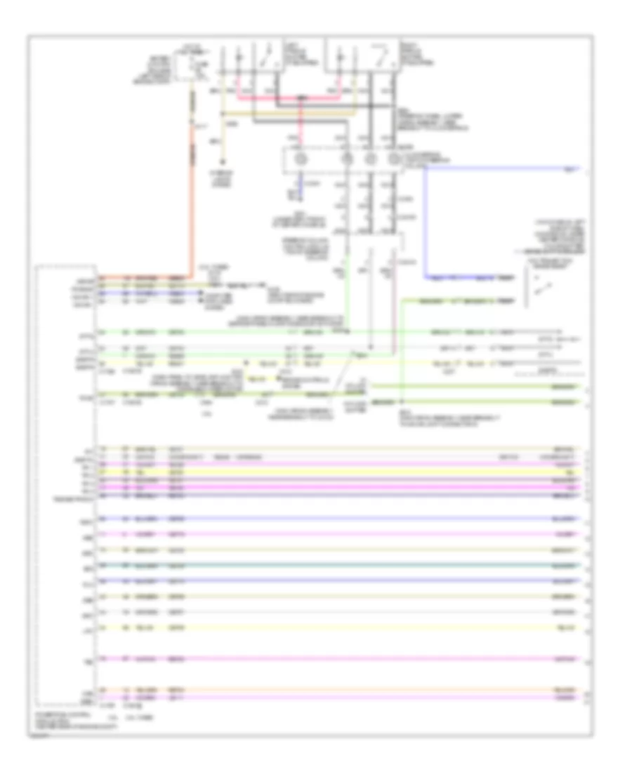
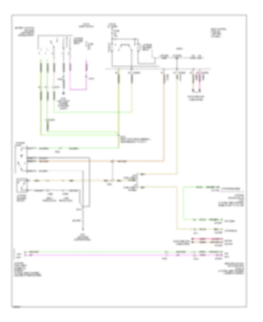
Manual A/C Wiring Diagram (1 of 4) for Ford Explorer Police Interceptor 2013
List of elements for Manual A/C Wiring Diagram (1 of 4) for Ford Explorer Police Interceptor 2013:
- (near breakout to front controls interface module(fcim))
- Auxiliary blower circuit
- Battery junction box (bjb) (left side of engine compt)
- Blower motor relay
- Blwr rly
- C212
- C228a
- C228b
- Ch122
- Ch123
- Ch207
- Ch208
- Ch228
- Ch229
- Ch238
- Ch239
- Cha35
- Cha36
- Cha37
- Computer data lines system
- Defogger system
- Defrost req
- Defrost/panel/ floor mode door actuator (right side of hvac unit)
- Driv temp dr ccw
- Driv temp dr cw
- Evap
- Feedback
- Fuse 40a
- Fuse 5a
- G200 (under left front of center console)
- Gd215
- Gnd
- Hot at all times
- Hot w/ run/start relay energized
- Hvac module
- Left temperature blend door actuator (right side of hvac unit)
- Lh111
- Mode dr 1 ccw
- Mode dr 1 cw
- Mode dr fdbk
- Ms can +
- Ms can -
- Rear ctrl blower output
- Rear sig feed 1
- Rear sig feed 2
- Rear sig feed 3
- Rear temp input
- Recirc ccw
- Recirc cw
- Return
- Rh111
- S123
- S215
- S216 (main wiring assembly, near breakout to c2123)
- Sbp46
- Temp dr fdbk
- Var blwr ctrl
- Vbatt
- Vdb06
- Vdb07
- Vh101
- Vh406
- Vh436
- Vh438
- Vh440
- Vha09
- Vha18
- Vha25
- Vha39
- Vref
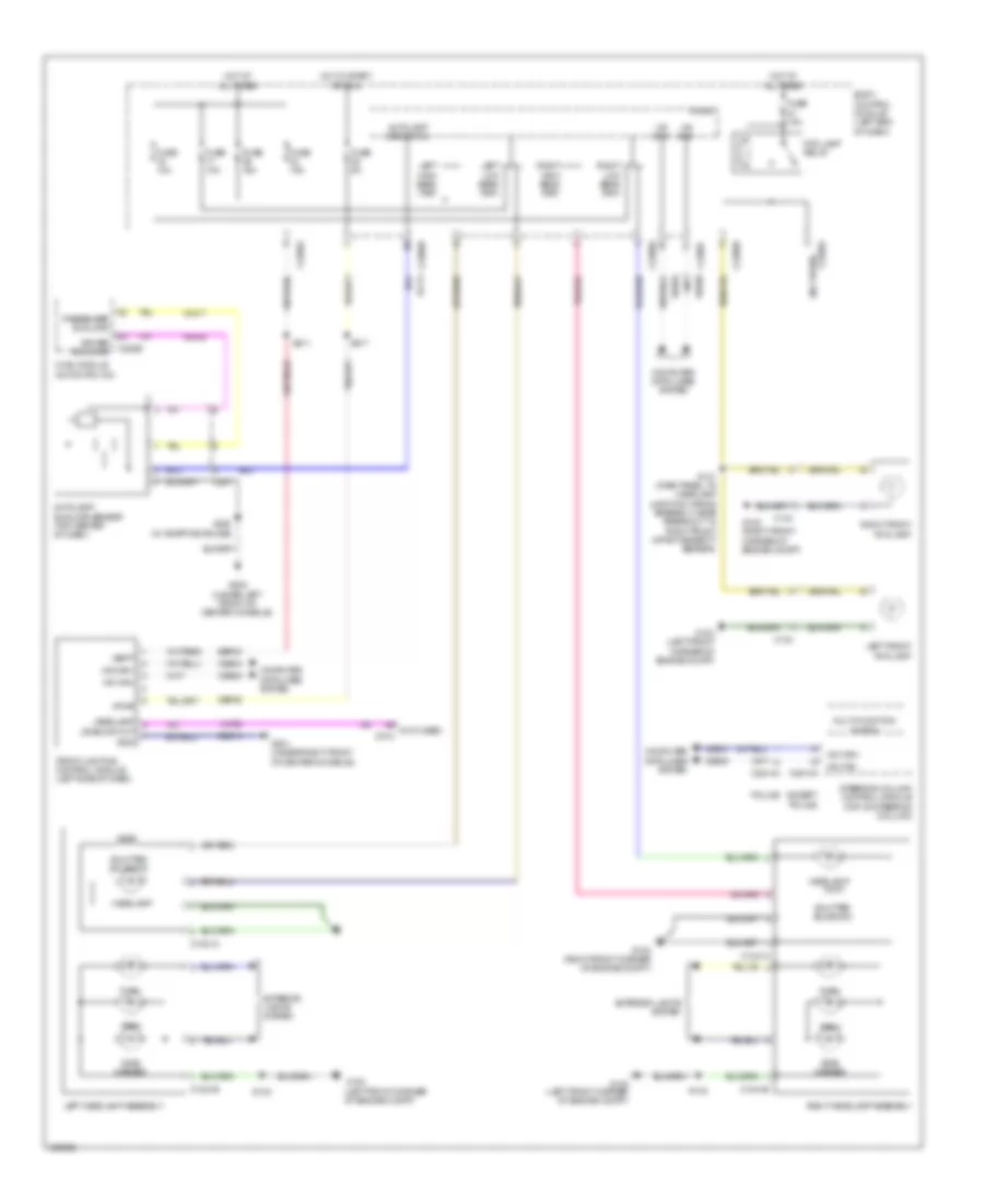
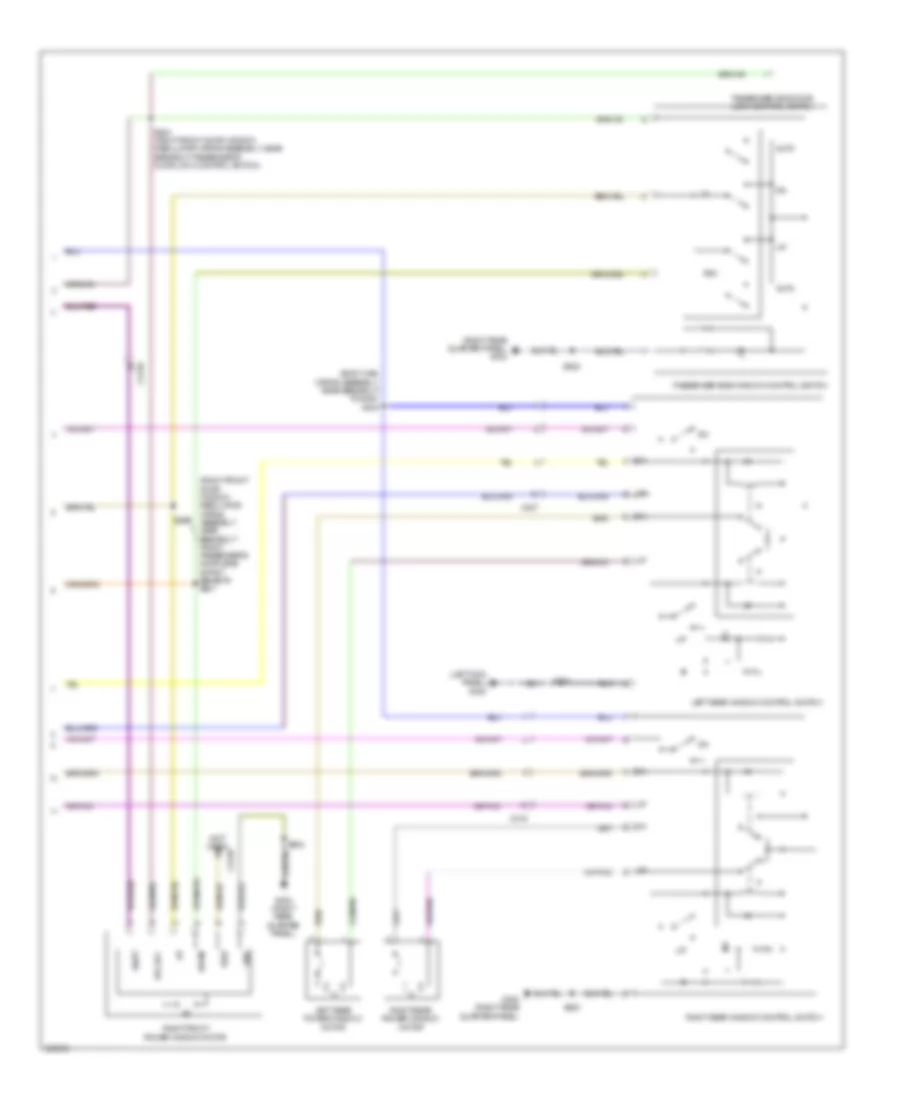
Manual A/C Wiring Diagram (2 of 4) for Ford Explorer Police Interceptor 2013
List of elements for Manual A/C Wiring Diagram (2 of 4) for Ford Explorer Police Interceptor 2013:
- (center of hvac unit) blower motor speed control
- (front center of hvac unit) blower motor
- (near breakout blower motor) s229
- (top left of hvac unit) fresh/recirculation door actuator
- Aux mode door ccw
- Aux mode door cw
- Aux temp door ccw
- Aux temp door cw
- Auxiliary blower circuit
- C228b
- Ch112
- Ch242
- Ch243
- Ch244
- Ch245
- Cha05
- Evaporator discharge air temperature sensor (right side of hvac unit)
- G200 (under left front of center console)
- Gnd
- Humidity sens
- Humidity sensor
- Hvac module
- In vehicle temp sns
- In-vehicle temperature/ humidity sensor (left side of dash)
- Mode output
- Mot+
- Mot-
- Pwm
- Pwm com
- Rear blower rly
- Vh413
- Vh414
- Vha38
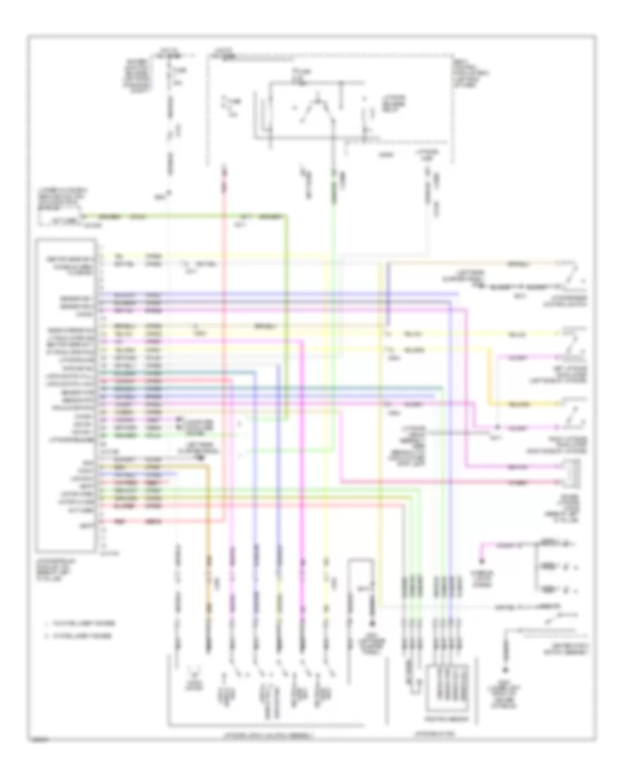
Manual A/C Wiring Diagram (3 of 4) for Ford Explorer Police Interceptor 2013
List of elements for Manual A/C Wiring Diagram (3 of 4) for Ford Explorer Police Interceptor 2013:
- (dash panel to headlamp junction wiring assembly, near breakout to battery junction box (bjb))
- (dash panel to headlight junction wiring assembly, near breakout to windshield wiper motor) s143
- (engine control sensor & fuel charge wiring assembly, near breakout coil on plug (cop) 2) (2.0l turbo) s176
- (engine control sensor & fuel charge wiring assembly, near breakout fuel injector 3) (3.5l) s156
- 2.0l turbo
- 3.5l
- A/c clutch relay
- A/c compressor clutch field coil (lower left front of engine)
- A/c pressure transducer (right front of engine compt)
- Aat
- Accr
- Acpt
- Ambient air temperature (aat) sensor (behind left side of grille)
- Battery junction box (bjb) (left side of engine compt)
- Body control module (bcm) (left end of dash)
- C1381b
- C1381e
- C139
- C140
- C175b
- C175e
- C2280a
- C2280b
- Cec07 (or cec01)
- Cec08 (or cec02)
- Ch302
- Cht
- Computer data lines system
- Ect
- Evdc
- Externally controlled variable displacement compressor (evdc) (2.0l turbo) (front right of engine compt)
- Fuse 10a
- Fuse 5a
- Fuse 70a 10a
- G103 (left front corner of engine compt)
- Hfc
- Hot at all times
- Hot w/ pcm power relay energized
- Hot w/ run/start relay energized
- Hs can +
- Hs can -
- Le424
- Lfc
- Powertrain control module (pcm) (center rear of engine compt)
- Re405 (or re454)
- Re407
- S104
- S113
- S121
- S217
- Sigrtn
- Vdb04
- Vdb05
- Ve462
- Ve712
- Ve716
- Vh407
- Vh433
- Vref
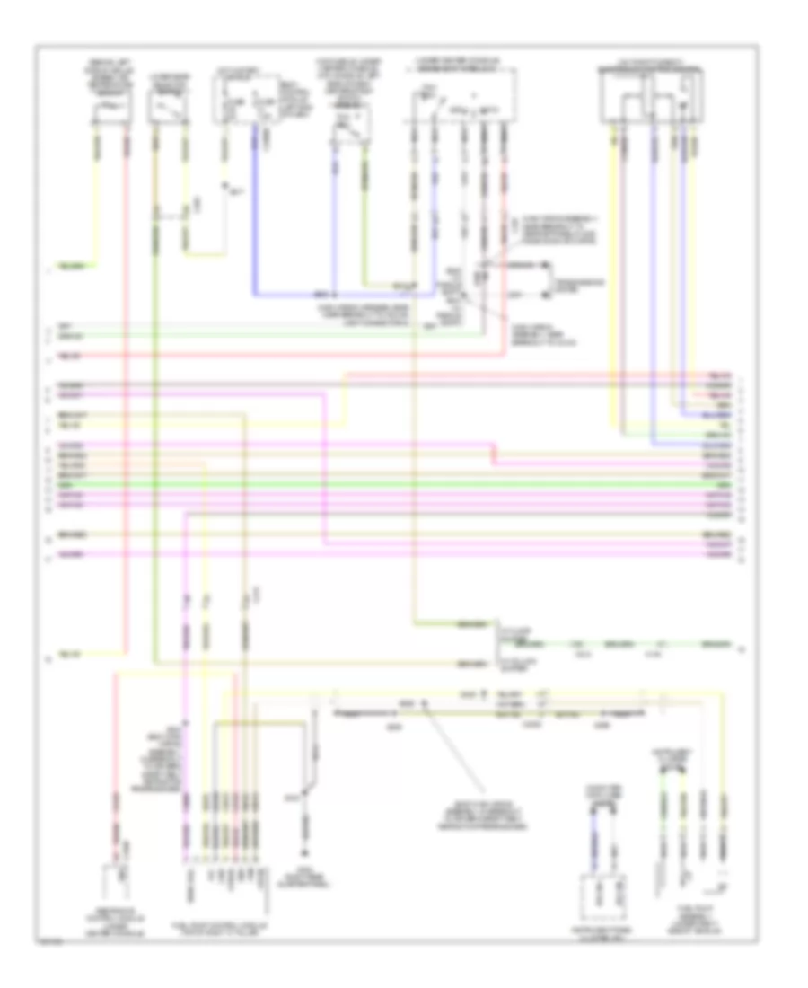
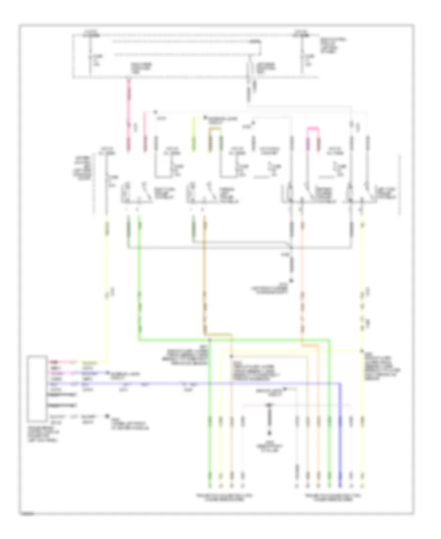
Manual A/C Wiring Diagram (4 of 4) for Ford Explorer Police Interceptor 2013
List of elements for Manual A/C Wiring Diagram (4 of 4) for Ford Explorer Police Interceptor 2013:
- (left front corner of engine compt) g103
- 3.5l
- Battery junction box (bjb) (left side of engine compt)
- C192
- Cooling fan high (hfc) relay 1
- Cooling fan high (hfc) relay 2
- Cooling fan low (lfc) relay
- Cylinder head temperature sensor (3.5l turbo: top rear of engine) (except 3.5l turbo: top center of engine)
- Engine coolant temperature (ect) sensor (2.0l turbo) (rear of engine)
- Engine cooling fan motor 1 (except 2.0l turbo) engine cooling fan motor 2 (2.0l turbo) (except 2.0l turbo: behind left side of radiator) (2.0l turbo: behind right side of radiator)
- Engine cooling fan motor 2 (except 2.0l turbo) engine cooling fan motor 1 (2.0l turbo) (except 2.0l turbo: behind right side of radiator) (2.0l turbo: behind left side of radiator)
- Fuse 10a
- Fuse 25a
- Fuse 40a
- G102 (right front corner of engine compt)
- Hot at all times
- Hot w/ pcm power relay energized
- S113
- S182 (dash panel to headlamp junction wiring assembly, near breakout to battery junction box (bjb))
ANTI-LOCK BRAKES
Anti-lock Brakes Wiring Diagram for Ford Explorer Police Interceptor 2013
List of elements for Anti-lock Brakes Wiring Diagram for Ford Explorer Police Interceptor 2013:
- (near breakout to windshield wiper motor) s112
- (not used)
- 2.0l
- 3.5l
- Anti-lock brake system module (left rear of engine compt)
- Battery junction box (left side of engine compt)
- Body control module (bcm) (left end of dash)
- Bpp
- Bps
- Brake booster vacuum sensor (front of brake booster)
- Brake pedal position (bpp) switch (above brake pedal)
- C1381b
- C139
- C175b
- C213
- C2280a
- C2280f vdb05
- C2414a
- C2414b
- C263
- C3049
- C310b
- Cbb92
- Ccb08
- Ces09
- Computer data lines system
- Except police
- Exterior lights system
- Fuse 10a
- Fuse 15a
- Fuse 40a
- Fuse 50a
- G103 (left front corner of engine compt)
- G106 (right side of engine compt bulkhead)
- G201 (under right front of center console)
- Gd120
- Gd214
- Gnd
- Hot at all times
- Hot in run or start
- Hs can +
- Hs can -
- Hs can yaw+
- Hs can yaw-
- Hs can+
- Hs can-
- Instrument panel cluster (ipc)
- Lca37
- Left front wheel speed sensor (left front wheel hub assembly)
- Left rear wheel speed sensor (left rear wheel hub assembly)
- Lf sens hi
- Lf sens lo
- Logic gnd
- Lr sens hi
- Lr sens lo
- Micro
- Mtr b+
- Nca
- Police
- Powertrain control module (center rear of engine compt)
- Pwr gnd
- Rca17
- Rca18
- Rca19
- Rca20
- Rca36
- Restraints control module (rcm) (under center console)
- Rf sens hi
- Rf sens lo
- Right front wheel speed sensor (right front wheel hub assembly)
- Right rear wheel speed sensor (right rear wheel hub assembly)
- Rr sens hi
- Rr sens lo
- S114 (3.5l)
- S119
- S205
- S211
- Sbb05
- Sbb43
- Sbp23
- Sbp24
- Steering column control module (top of steering column)
- Vacuum pwr
- Vacuum return
- Vacuum sig
- Valve b+
- Vbatt
- Vca03
- Vca04
- Vca05
- Vca06
- Vca23
- Vca24
- Vca36
- Vdb04
- Vdb05
- Vpwr
ANTI-THEFT
Forced Entry Wiring Diagram, with Intelligent Access (1 of 2) for Ford Explorer Police Interceptor 2013
List of elements for Forced Entry Wiring Diagram, with Intelligent Access (1 of 2) for Ford Explorer Police Interceptor 2013:
- (2 led's)
- (5 led's)
- (body main wiring assembly, near breakout to c312)
- (body main wiring assembly, near breakout to g300) s304
- (left kick panel) g300
- (right rear quarter panel) g302
- (under right front of center console) g201
- Accessory delay relay
- Ajar
- All lock
- Backup transceiver (under center console)
- Body control module (left end of dash)
- C210
- C211
- C2153d
- C2153e
- C2280a
- C2280b
- C2280c
- C2280d
- C2280f
- C237
- C3138
- C3139
- C316
- C327
- Clock
- Computer data lines system
- Cpk19
- Cpk23
- Cpk28
- Cpl11
- Cpl25
- Cpl26
- Cpl31
- Cpl36
- Cpl39
- Cpl51
- Cpl52
- Cpl84
- Data
- Door lock
- Door unlock
- Dr door unlock
- Driver side door lock control switch
- Fuse 10a
- Fuse 15a
- Fuse 20a
- G102 (right front corner of engine compt)
- G201 (under right front of center console)
- G300 (left kick panel)
- G302 (right rear quarter panel)
- Gd214
- Gnd
- Hood ajar
- Hood switch (left front of engine compt)
- Hot at all times
- Internal antenna
- K line
- Keypad illm(fet)
- Left front door latch
- Left rear door latch
- Lf door ajar
- Lock
- Lpk32
- Lr door ajar
- Memory set switch
- Memory systems
- Micro
- Ms can +
- Ms can -
- Ms can+
- Ms can-
- Not used
- Power distribution system
- Pwr gnd
- Remote function actuator (rfa) module (under glove box)
- Rf door ajar
- Right front door latch
- Right rear door latch
- Rke receiver
- Rpk32
- Rpk39
- Rr door ajar
- S211
- S301 (body main wiring assembly, near breakout to g300)
- S312
- S315 (body main wiring assembly, near breakout to c3403)
- S325
- S500
- S501
- S602
- S800
- Set 1
- Set 2
- Set 3
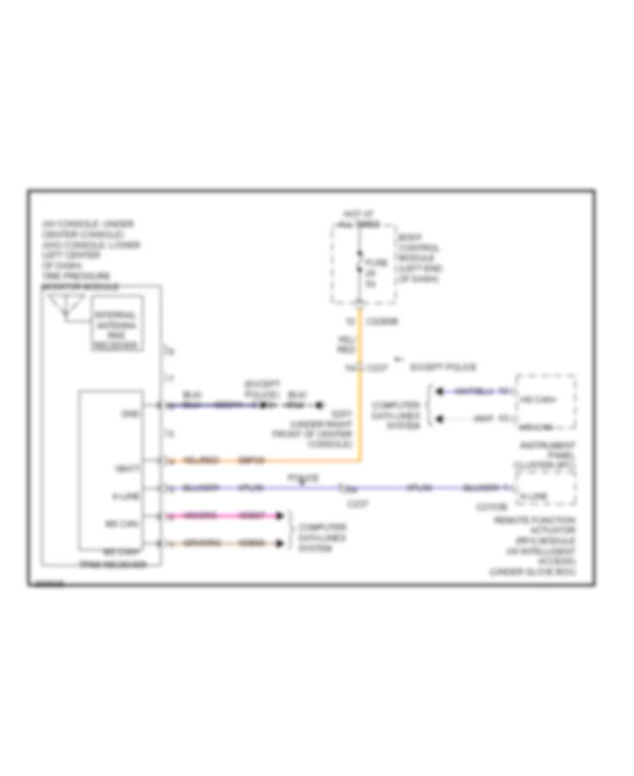
- Tire pressure monitor module (under center console)
- Trunk, tailgate, fuel doors system
- Unlock
- Vbatt
- Vdb06
- Vdb07
- Vpk32
- Vpk33
- Vpk39
- Vpk40
- Vpl56
- W/ memory
- W/o memory
Forced Entry Wiring Diagram, with Intelligent Access (2 of 2) for Ford Explorer Police Interceptor 2013
List of elements for Forced Entry Wiring Diagram, with Intelligent Access (2 of 2) for Ford Explorer Police Interceptor 2013:
- (2 led's)
- (base of left "d" pillar) rear passive start antenna
- (center of rear bumper) liftgate intelligent access (ia) antenna
- 1/2
- 3/4
- 5/6
- 7/8
- 9/0
- Ant +
- Ant -
- Bpp
- C210
- C211
- C2153a
- C2153b
- C2153c
- C237
- C3138
- C3139
- C406
- C510
- C610
- Ccb08
- Cdc35
- Center passive start antenna (under center console)
- Cpk29
- Cpk30
- Cpk31
- Cpl45
- Exterior lights system
- Front passive start antenna (under center console)
- G201 (under right front of center console)
- G300 (left kick panel)
- G302 (right rear quarter panel)
- Gd214
- Gnd
- Keyless entry keypad
- Keypad a
- Keypad b
- Keypad c
- Left front exterior door handle
- Liftgate sw
- Lock
- Logic gnd
- Micro
- Passenger side door lock control switch
- Red
- Remote function actuator (rfa) module (under glove box)
- Right front exterior door handle
- Rpk01
- Rpk02
- Rpk05
- Rpk06
- Rpk07
- Rpk08
- S201
- S232 (main wiring assembly, near breakout to joint connector 1 (i-can))
- S501
- S602
- Sbp23
- Sbp27
- Start/ stop 1 (active high)
- Start/stop 1
- Start/stop switch
- Trunk, tailgate, fuel doors system
- Unlock
- Vbatt
- Vpk01
- Vpk02
- Vpk05
- Vpk06
- Vpk07
- Vpk08
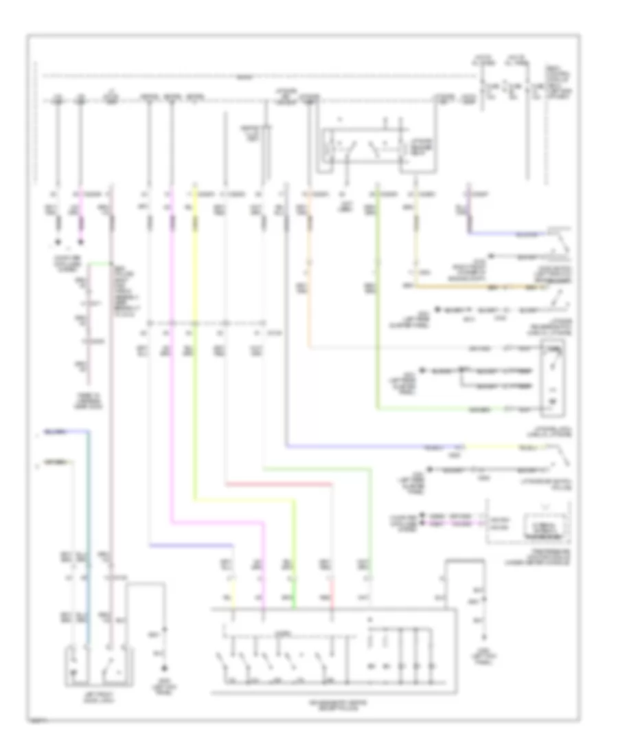
Forced Entry Wiring Diagram, without Intelligent Access (1 of 2) for Ford Explorer Police Interceptor 2013
List of elements for Forced Entry Wiring Diagram, without Intelligent Access (1 of 2) for Ford Explorer Police Interceptor 2013:
- (2 led's)
- (5 led's)
- (body main wiring assembly, near breakout to c312) s325
- (body main wiring assembly, near breakout to c3403) s315
- (body main wiring assembly, near breakout to g300)
- (body main wiring assembly, near breakout to g300) s304
- Accessory delay relay
- All lock/ unlock relay
- Body control module (bcm) (left end of dash)
- C2280c
- C2280d
- C3138
- C3139
- C316
- C327
- Cpk19
- Cpk23
- Cpl31
- Cpl36
- Cpl39
- Door lock
- Door unlock
- Driver door unlock relay
- Driver side door lock control switch
- Fuse 15a
- Fuse 20a
- G300 (left kick panel)
- G302 (right rear quarter panel)
- Hot at all times
- Left rear door latch
- Lock
- Lr door ajar
- Memory set switch
- Memory systems
- Micro
- Passenger side door lock control switch
- Power windows system
- Rf door ajar
- Right front door latch
- Right rear door latch
- Rr door ajar
- S301
- S312
- S500
- S501
- S602
- S700
- S800
- Set 1
- Set 2
- Set 3
- Unlock
- W/ memory
- W/o memory
Forced Entry Wiring Diagram, without Intelligent Access (2 of 2) for Ford Explorer Police Interceptor 2013
List of elements for Forced Entry Wiring Diagram, without Intelligent Access (2 of 2) for Ford Explorer Police Interceptor 2013:
- (not used)
- 1/2
- 3/4
- 5/6
- 7/8
- 9/0
- Ajar
- Body control module (bcm) (left end of dash)
- C211
- C2238
- C2280b
- C2280c
- C2280d
- C2280f
- C3138
- C432
- C934
- C935
- Computer data lines system
- Cpk29
- Cpk30
- Cpk31
- Cpl45
- Fuse 10a
- Fuse 15a
- G102 (right front corner of engine compt)
- G300 (left kick panel)
- G301 (left rear quarter panel)
- Hood ajar
- Hood switch (left front of engine compt)
- Hot at all times
- Internal antenna rke receiver
- Keyless entry keypad (except police)
- Keypad a
- Keypad b
- Keypad c
- Keypad illum (fet)
- Left front door latch
- Lf door ajar
- Liftgate ajar
- Liftgate key switch (police)
- Liftgate key unlock
- Liftgate latch (manual liftgate)
- Liftgate release relay
- Liftgate release switch (manual liftgate)
- Liftgate sw
- Micro
- Ms can+
- Ms can-
- Nca
- Red
- S280 (police) (body main wiring assembly, near breakout to c213)
- S410
- S501
- Taped to harness near c2238
- Tire pressure monitor module (under center console)
- Vdb06
- Vdb07
Passive Anti-theft Wiring Diagram, with Intelligent Access for Ford Explorer Police Interceptor 2013
List of elements for Passive Anti-theft Wiring Diagram, with Intelligent Access for Ford Explorer Police Interceptor 2013:
- (center rear of engine compt) powertrain control module (pcm)
- 2.0l turbo
- 3.5l
- 3.5l turbo
- Ant+
- Ant-
- Backup transceiver (under center console)
- Body control module (bcm) (left end of dash)
- C1381b
- C1551b
- C175b
- C211
- C2153a
- C2153c
- C2153d
- C2153e
- C2280a
- C2280b
- C2280f
- C237
- Cdc35
- Center passive start antenna (under center console)
- Clock
- Computer data lines system
- Data
- Front passive start antenna (under center console)
- Fuse 15a
- Fuse 20a
- G201 (under right front of center console)
- Gd214
- Gnd
- Hot at all times
- Hs can +
- Hs can -
- Hs can+
- Hs can-
- Instrument panel cluster (ipc)
- Internal antenna/ rke receiver
- K-line
- Logic gnd
- Lpk32
- Micro
- Ms can+
- Ms can-
- Pwr gnd
- Rear passive start antenna (base of left "d" pillar)
- Remote function actuator module (under glove box)
- Rpk05
- Rpk06
- Rpk08
- Rpk32
- S201
- S211
- Sbp23
- Sbp27
- Start/ stop 1 (active high)
- Start/stop 1
- Start/stop switch
- Tire pressure monitor module (under center console)
- Vbatt
- Vdb04
- Vdb05
- Vdb06
- Vdb07
- Vpk05
- Vpk06
- Vpk08
- Vpk32
- Vpk33
- Vpl56
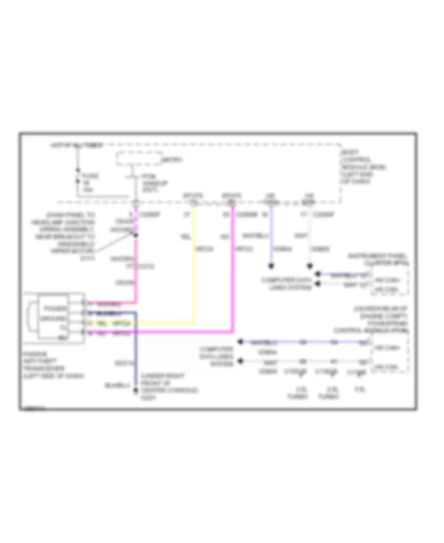
Passive Anti-theft Wiring Diagram, without Intelligent Access for Ford Explorer Police Interceptor 2013
List of elements for Passive Anti-theft Wiring Diagram, without Intelligent Access for Ford Explorer Police Interceptor 2013:
- (center rear of engine compt) powertrain control module (pcm)
- (dash panel to headlamp junction wiring assembly, near breakout to windshield wiper motor) s111
- (under right front of center console) g201
- 2.0l turbo
- 3.5l
- 3.5l turbo
- Body control module (bcm) (left end of dash)
- C1381b
- C1551b
- C175b
- C212
- C2280b
- C2280f
- Ce436
- Computer data lines system
- Epats rx
- Epats tx
- Fuse 10a
- Gd214
- Ground
- Hot at all times
- Hs can+
- Hs can-
- Instrument panel cluster (ipc)
- Micro
- Passive anti-theft transceiver (left side of dash)
- Pcm wakeup (fet)
- Power
- Vdb04
- Vdb05
- Vrt23
- Vrt24
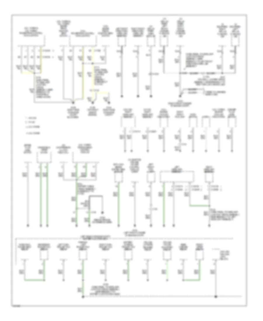
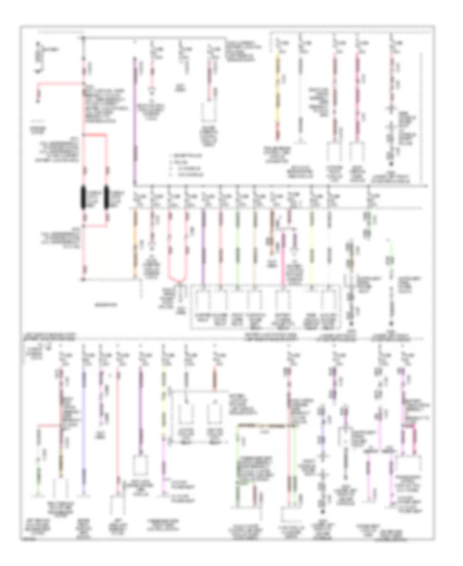
BODY CONTROL MODULES
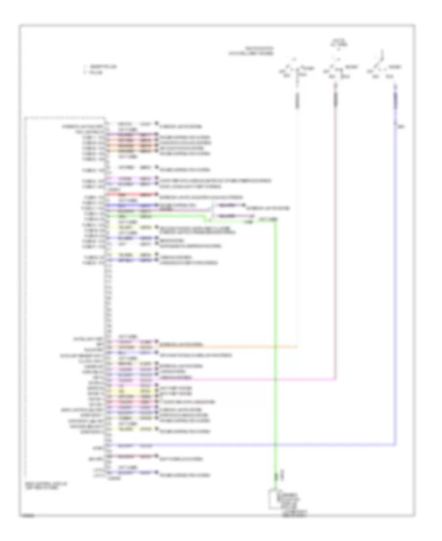
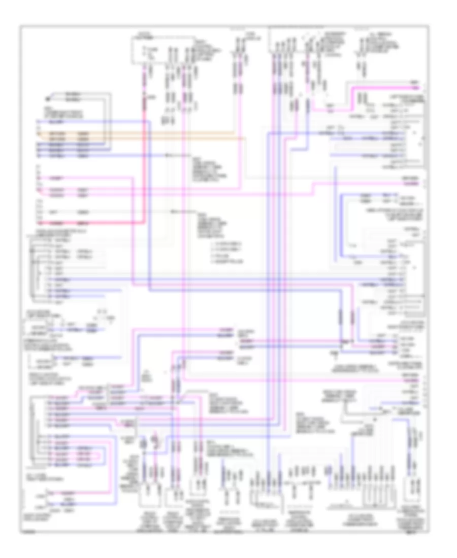
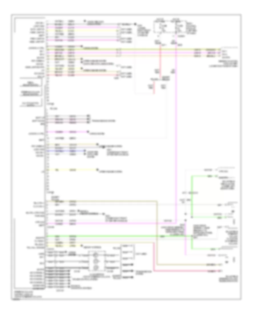
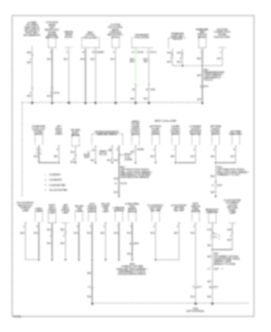
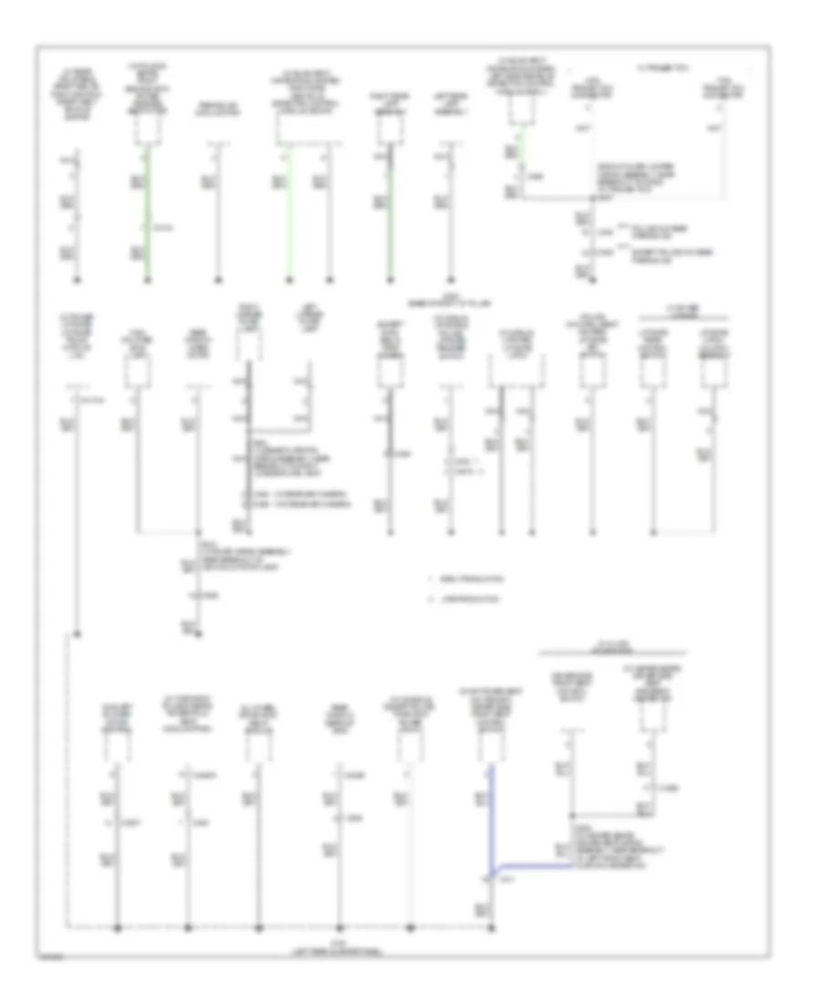
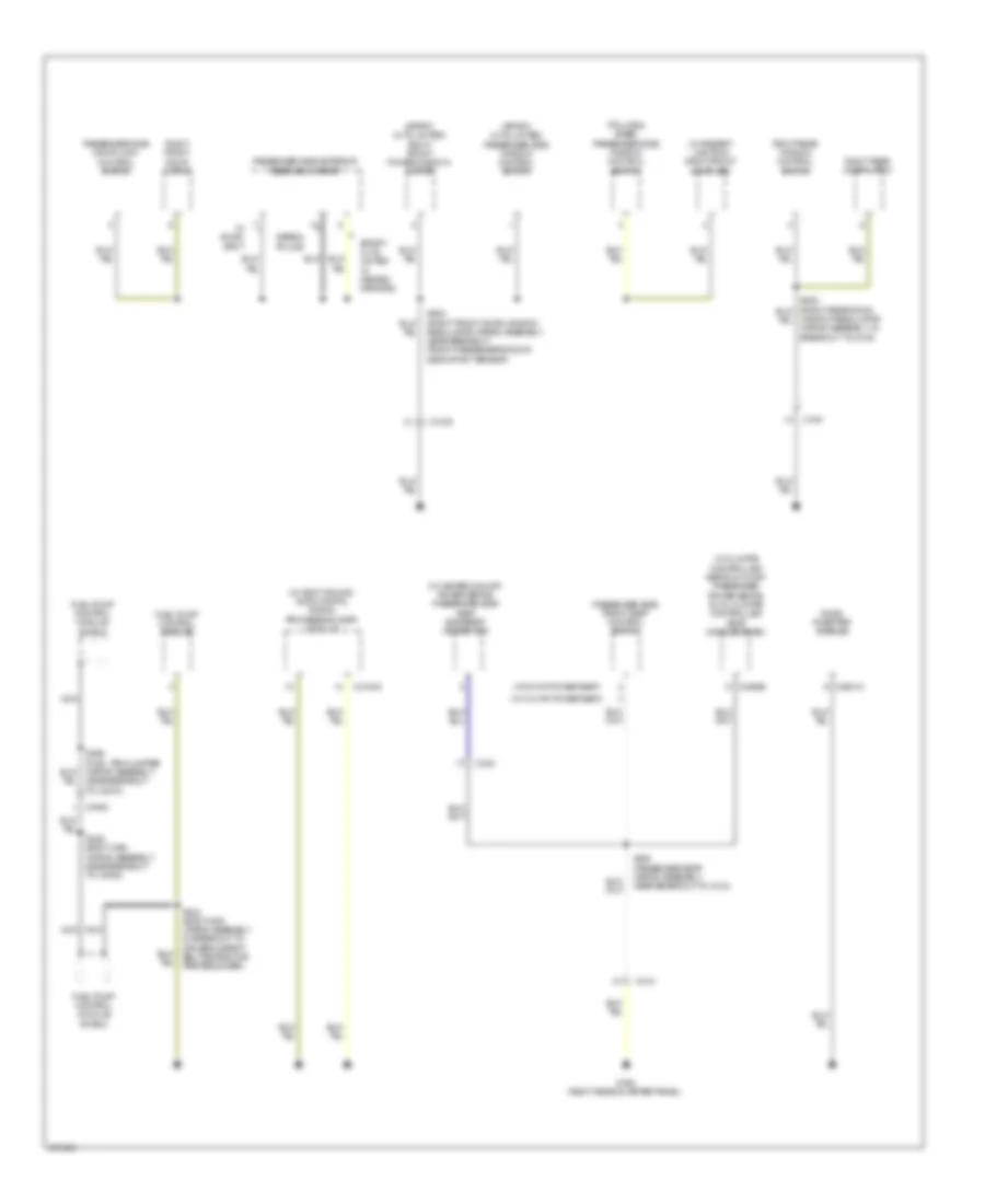
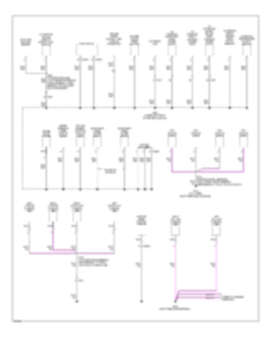
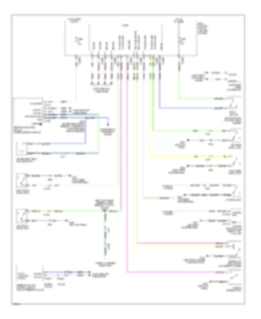
Body Control Module Wiring Diagram (1 of 2) for Ford Explorer Police Interceptor 2013
List of elements for Body Control Module Wiring Diagram (1 of 2) for Ford Explorer Police Interceptor 2013:
- (not used)
- (w/o intelligent access)
- Acc
- Acc/run
- Air conditioning & headlights systems
- Air conditioning system
- Air conditioning, instrument cluster, interior lights & transmissions systems
- Anti-theft system
- Autolamp sensor input
- Back lighting led (fet)
- Body control module (left end of dash)
- Bpp
- Bsi (fet)
- C2280a
- C2280b
- C299
- Cbp31
- Cbp35
- Cbp36
- Cbp37
- Cbp38
- Cbp41
- Cbp42
- Ccb08
- Cdc30
- Cdc33
- Cdc34
- Cdc35
- Cet53
- Cls32
- Clutch input
- Computer data lines & electronic power steering systems
- Computer data lines system
- Cpk35
- Cpk36
- Crh04
- Door locks & anti-theft systems
- Epats rx
- Epats tx
- Except police
- Exterior lights system
- Exterior lights, navigation & sound systems
- Fog lamp relay
- Fuse 11, 10a
- Fuse 23, 15a
- Fuse 24, 15a
- Fuse 26, 5a
- Fuse 27, 20a
- Fuse 28, 15a
- Fuse 29, 20a
- Fuse 31, 5a
- Fuse 32, 15a
- Fuse 34, 10a
- Fuse 35, 5a
- Fuse 36, 10a
- Fuse 37, 10a
- Fuse 38, 10a
- Fuse 41, 7.5a
- Fuse 42, 5a
- Fuse 44, 10a
- Fuse 45, 5a
- Fuse 46, 10a
- Fuse 9, 10a
- Generic function module (police) (lower right side of dash)
- Hazard sw
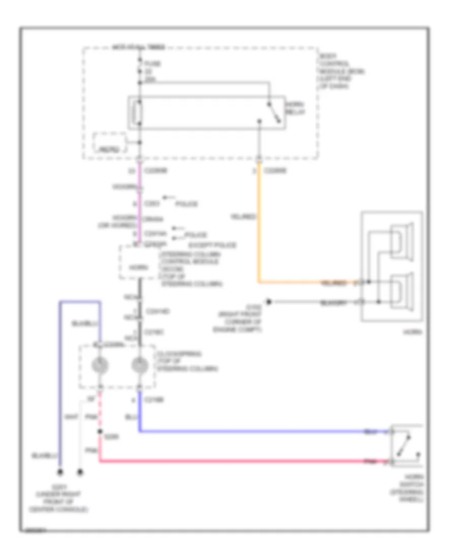
- Horn relay
- Horns system
- Hot at all times
- Ignition switch
- Interior lighting (fet)
- Interior lights system
- Key in
- Lin 01
- Lin 04
- Mirrors & power tops systems
- Ms can +
- Ms can -
- Navigation & sound systems
- Off
- Police
- Power distribution system
- Red
- Ripcord security
- Run
- Run/start
- S201
- Sbp09
- Sbp11
- Sbp23
- Sbp24
- Sbp26
- Sbp27
- Sbp28
- Sbp29
- Sbp46
- Seats system
- Shift interlock system
- Start
- Start/stop 1
- Start/stop 2
- Starting/charging system
- Strt/stop (led) fet
- Vbatt
- Vdb06
- Vdb07
- Vdn01
- Vlf14
- Vln04
- Vln33
- Vrt23
- Vrt24
- Warning systems
- White light (fet)
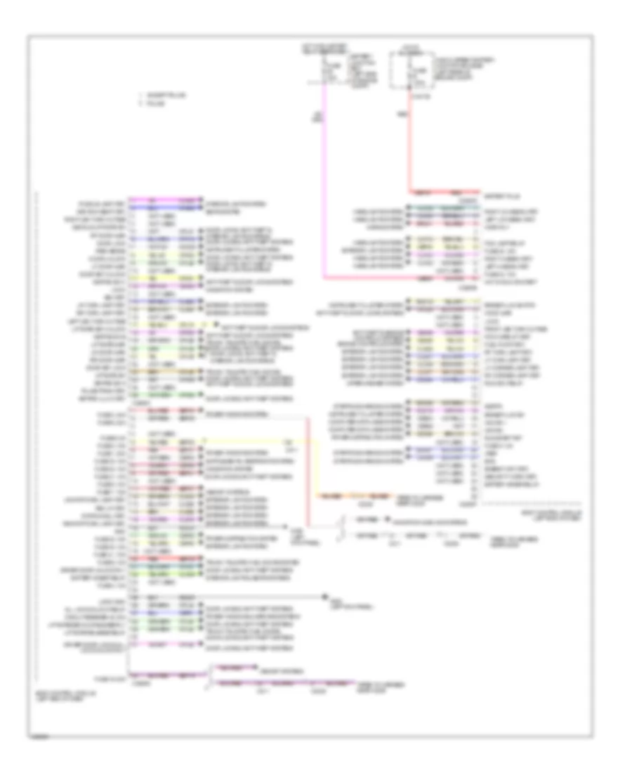
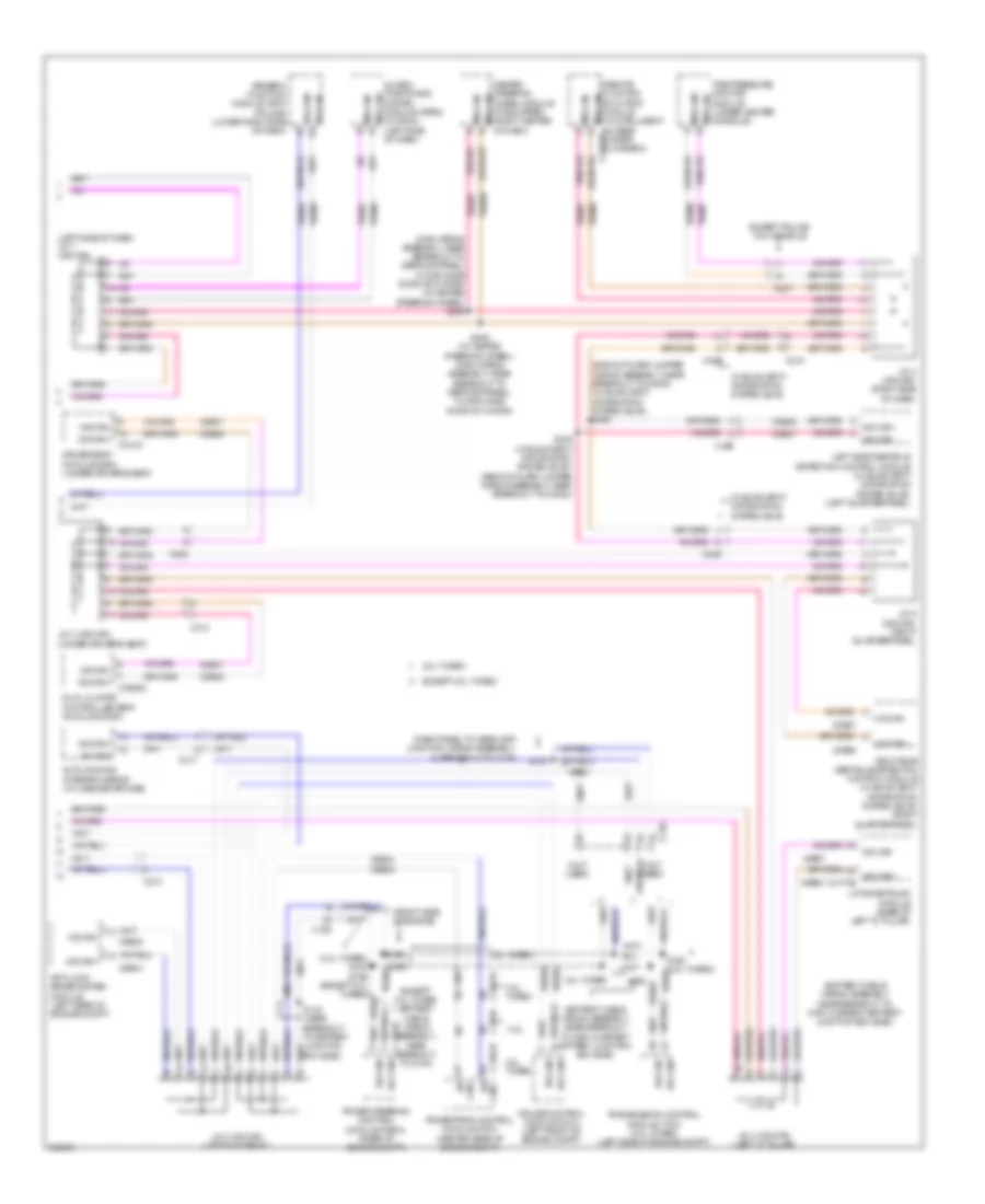
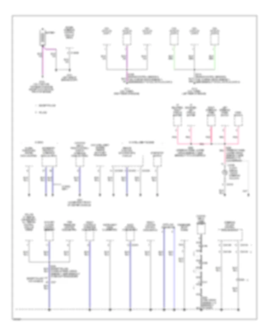
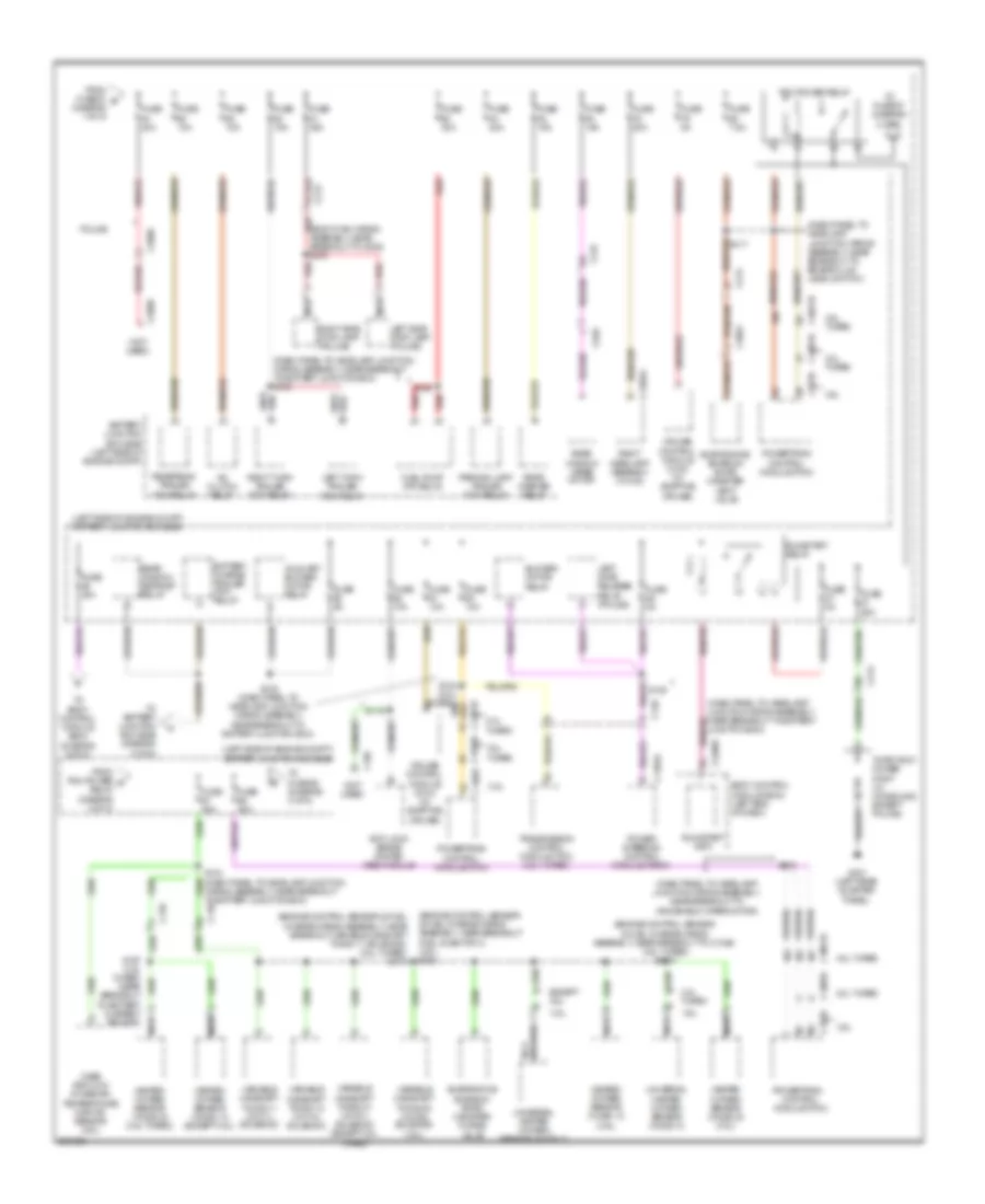
Body Control Module Wiring Diagram (2 of 2) for Ford Explorer Police Interceptor 2013
List of elements for Body Control Module Wiring Diagram (2 of 2) for Ford Explorer Police Interceptor 2013:
- (not used)
- 3rd row seat (fet)
- All lock/unlock relay
- Anti-theft & door locks systems
- Anti-theft & engine controls systems engine controls system
- Battery junction box (left side of engine compt)
- Battery plus
- Battery saver relay
- Bcs
- Body control module (left end of dash)
- Brake fluid sw
- Brake fluid sw rtn
- Bsi (fet)
- C1617b
- C211
- C2238
- C2280c
- C2280d
- C2280e
- C2280f
- C2280g
- Cbb94
- Cbp01
- Cbp30
- Cbp32
- Cbp33
- Cbp34
- Cbp40
- Cdc55
- Cdc64
- Ce226
- Ce436
- Circuit breaker 48, 30a
- Clf02
- Clf03
- Clf04
- Clf05
- Clf06
- Clf07
- Clf12
- Cln09
- Cln25
- Cls18
- Cls19
- Cls21
- Cls23
- Cls24
- Cls25
- Cls28
- Cls52
- Cmc19
- Cmc25
- Computer data lines system
- Cpk19
- Cpk23
- Cpk28
- Cpk29
- Cpk30
- Cpk31
- Cpl25
- Cpl26
- Cpl31
- Cpl34
- Cpl36
- Cpl39
- Cpl45
- Cpl51
- Cpl52
- Cpl58
- Cpl74
- Cpl84
- Cps48
- Decklid/liftgate sw
- Door key lock
- Door key unlock
- Door lock
- Door locks & anti-theft systems
- Door locks, anti-theft &
- Door locks, anti-theft & interior lights systems
- Door locks, anti-theft & interior lights systems door locks & anti-theft systems
- Door unlock
- Driver door lock & all lock/unlock rly
- Driver door unlock rly
- Energy mgt (fet)
- Except police
- Exterior lights system
- Fog lamp relay
- Front led turn outage
- Fuel pump (fet)
- Fuse 1, 30a
- Fuse 19, 20a
- Fuse 2, 15a
- Fuse 21, 10a
- Fuse 3, 30a
- Fuse 30, 15a
- Fuse 30a
- Fuse 31, 5a
- Fuse 32, 15a
- Fuse 33, 10a
- Fuse 34, 10a
- Fuse 4, 10a
- Fuse 40, 10a
- Fuse 41, 7.5a
- Fuse 43, 10a
- Fuse 5, 20a
- Fuse 6, 5a
- Fuse 7, 7.5a
- Fuse 8, 10a
- Fuse 9, 10a
- Fuse b 100a
- G300 (left kick panel)
- Gd233
- Gnd
- Headlights system
- High current battery junction box (bjb) (left rear of engine compt)
- Hood ajar
- Horn rly
- Horns system
- Hot at all times
- Hot in run or start
- Hot w/ run/start relay energized
- Hs can +
- Hs can -
- Instrument cluster system
- Interior lights & seats systems
- Interior lights system
- Interior lights systems
- Keypad illum (fet)
- Keypad sw a
- Keypad sw b
- Keypad sw c
- Ldc59
- Left hi beam (fet)
- Left led turn outage
- Left low beam (fet)
- Lf door ajar
- Lf turn lamp (fet)
- Lh corner lamp (fet)
- Liftgate ajar
- Liftgate key unlock
- Liftgate release relay
- Liftgate sw
- Liftgate/decklid release rly
- Lin 02
- Lin 03
- Logic gnd
- Lr door ajar
- Lr stop/turn lamp (fet)
- Lr turn lamp (fet)
- Memory systems
- Navigation & sound systems
- Navigation system
- Park brake
- Pcm wake up (fet)
- Police
- Power distribution system
- Power windows & mirrors systems
- Power windows system
- Puddle lamp (fet)
- Pulse train (fet)
- Rdc59
- Red
- Rev lp (fet)
- Rf door ajar
- Rf turn lamp (fet)
- Rh corner lamp (fet)
- Right hi beam (fet)
- Right led turn outage
- Right low beam (fet)
- Rmc19
- Rr door ajar
- Rr stop/turn lamp (fet)
- Rr turn lamp (fet)
- Run/acc relay
- Run/start fet
- Sbf16
- Sbp01
- Sbp02
- Sbp03
- Sbp05
- Sbp07
- Sbp09
- Sbp19
- Sbp21
- Sdc57
- Seats system
- Security horn (fet)
- Sigrtn
- Srh01
- Starting/charging system
- Stop/chmsl (fet)
- Taped to harness near c2238
- Trunk, tailgate, fuel doors system
- Trunk, tailgate, fuel doors, door locks & anti-theft systems
- Trunk, tailgate, fuel doors, door locks & anti-theft systems anti-theft & door locks systems
- Vdb04
- Vdb05
- Vdn03
- Vref
- Wiper/washer system
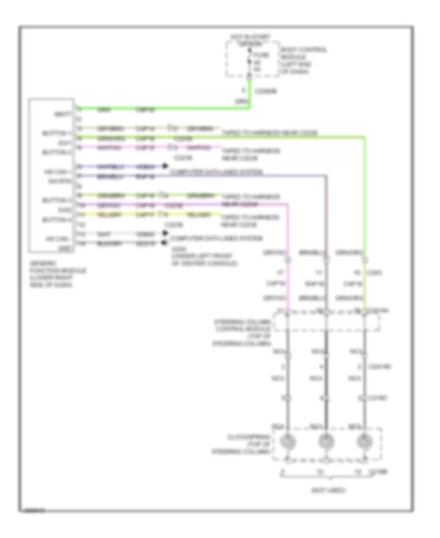
Generic Electronic Module Wiring Diagram for Ford Explorer Police Interceptor 2013
List of elements for Generic Electronic Module Wiring Diagram for Ford Explorer Police Interceptor 2013:
- (not used)
- Body control module (left end of dash)
- Button 1
- Button 2
- Button 3
- Button 4
- C218b
- C218c
- C2238
- C2280b
- C2414a
- C2414d
- C263
- Cap14
- Cap15
- Cap16
- Cap17
- Cap18
- Cap19
- Cbp42
- Clockspring (top of steering column)
- Computer data lines system
- Fuse 5a
- G200 (under left front of center console)
- Gd215
- Generic function module (lower right side of dash)
- Gnd
- Hot in start or run
- Hs can +
- Hs can -
- Nca
- Rap18
- Steering column control module (top of steering column)
- Sw rtn
- Sw1
- Sw2
- Taped to harness near c2238
- Vbatt
- Vdb04
- Vdb05
COMPUTER DATA LINES
Computer Data Lines Wiring Diagram (1 of 2) for Ford Explorer Police Interceptor 2013
List of elements for Computer Data Lines Wiring Diagram (1 of 2) for Ford Explorer Police Interceptor 2013:
- (body main wiring assembly, near breakout to c317)
- (left side of dash) j/c 1 (hs-can)
- (main wiring assembly near breakout to c2123)
- (w/ lane departure)
- Accessory protocol interface module (apim) (w/ sync)
- All terrain control module (atcm) (under center console)
- Audio control module (acm)
- Audio digital signal processing (dsp) module (w/ sony audio) (base of right "c" pillar)
- Body control module (bcm) (left end of dash)
- Breakout to c2123)
- C210
- C211
- C212
- C2280a
- C2280b
- C2280f
- C237
- C240a
- C2414a
- C263
- C291
- C312
- C3154a
- Data link connector (dlc) (left side of dash)
- Except police
- Front control/ display interface module (fcim)
- Front controls interface module (fcim)
- Front lighting control module (flm) (left side of dash)
- Fuse 15a
- G201 (under right front of center console)
- Gd214
- Head up display (hud) module (w/ adaptive cruise) (left side of dash)
- Hot at all times
- Hs can+
- Hs can-
- Hvac module
- I can+
- I can-
- Instrument panel cluster (ipc)
- J/c 1 (i-can) (right side of dash)
- J/c 3 (hs-can) (under front passenger's seat)
- J/c 4 (hs-can) (base of right "c" pillar)
- J/c 5 (hs-can) (right side of dash)
- J/c 6 (hs-can) (left side of dash)
- Ms can+
- Ms can-
- Ms can- c228a
- Ms can- i can-
- Occupant classification system module (ocsm) (under front passenger's seat)
- Parking aid module (pam) (right quarterpanel)
- Police
- Restraints control module (rcm) (under center console)
- S205
- S207 (main wiring assembly, near breakout to instrument panel cluster (ipc))
- S208 (main wiring assembly, near breakout to hs-can joint connector 6)
- S214 (w/ sync gen 1) (main wiring assembly near breakout to c2123)
- S219 (w/ sync gen 1) (main wiring assembly near
- S247
- S249
- S337 (w/ sony audio) (body main wiring assembly, near breakout to c3145a)
- S338 (w/ sony audio) (body main wiring assembly, near breakout to c3145a)
- S370 (w/ lane departure)
- S371
- Sbp24
- Steering column control module (sccm) (top of steering column)
- Vdb04
- Vdb04 c310b hs can+
- Vdb05
- Vdb06
- Vdb07
- Vdb13
- Vdb14
- W/ sony audio
- W/ sync gen 1
- W/ sync gen 2
- W/o sync gen 2
Computer Data Lines Wiring Diagram (2 of 2) for Ford Explorer Police Interceptor 2013
List of elements for Computer Data Lines Wiring Diagram (2 of 2) for Ford Explorer Police Interceptor 2013:
- (2.0l turbo) s191 s196 (except 2.0l turbo) vdb05
- (backup alarm jumper wiring assembly, near breakout to c4082) (w/ blind spot information system (blis)) s406
- (battery cable wiring assembly, near breakout to high current battery junction box (bjb))
- (dash panel to headlamp junction wiring assembly, in breakout to c139)
- (front side of engine)
- (left side of dash) j/c 7 (ms-can)
- (main wiring assembly, near breakout to defrost/panel/ floor mode door actuator) (w/ heated steering wheel) s248
- (not used)
- 2.0l turbo
- 3.5l
- 3.5l turbo
- Anti-lock brake system module (left rear of engine compt)
- Auto dimming interior mirror (w/ lane departure)
- C1381b
- C139
- C1463a
- C1551b
- C175b
- C210
- C213
- C2153e
- C237
- C300
- C312
- C317
- C3265c
- C341d
- C405
- C465
- Can+
- Can-
- Cruise control module (ccm) (left front of engine compt)
- Driver seat module (dsm) (under driver's seat)
- Dual climate controlled seat module (dcsm)
- Except 2.0l turbo
- Except 2.0l turbo (battery cable wiring assembly, near breakout to g100)
- Except police w/o console
- Generic function module (gfm) (police) (lower right side of dash)
- Global positioning system module (gpsm) (w/ sync) (left side of dash)
- Heated steering wheel module (if equipped) (right center of dash)
- Hs can+
- Hs can-
- J/c 2 (hs-can) (left kick panel)
- J/c 2 (ms-can) (right side of dash)
- J/c 3 (ms-can) (under driver's seat)
- J/c 4 (ms-can) (left "c" pillar)
- J/c 6 (ms-can) (right quarterpanel)
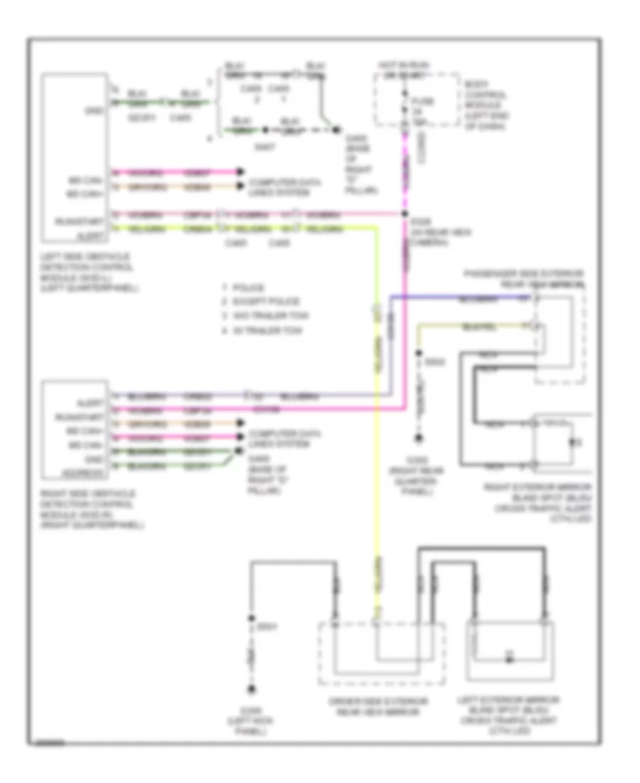
- Left side obstacle detection control module (w/ blind spot information system (blis)) (left quarterpanel)
- Liftgate/trunk module (base of left "d" pillar)
- Ms can+
- Ms can+ c4174b
- Ms can-
- Power steering control module (pscm) (rear of engine compt)
- Powertrain control module (pcm) (center rear of engine compt)
- Remote function actuator module (w/ intelligent access) (under glove box)
- Right side obstacle detection control module (w/ blind spot information system (blis)) (right quarterpanel)
- S133 (near breakout to battery junction box (bjb))
- S136
- S137
- S190
- S192 (2.0l turbo)
- S193
- S195
- S246 (w/ heated steering wheel) (main wiring assembly, near breakout to defrost/panel/ floor mode door actuator)
- S405 (w/ blind spot information system (blis)) (backup alarm jumper wiring assembly, near breakout to c4082)
- Tire pressure monitor module (under center console)
- Transmission control module (tcm) (2.0l turbo) (left side of engine compt)
- Vdb04
- Vdb05
- Vdb06
- Vdb07
- W/ blind spot information system (blis)
COOLING FAN
Cooling Fan Wiring Diagram for Ford Explorer Police Interceptor 2013
List of elements for Cooling Fan Wiring Diagram for Ford Explorer Police Interceptor 2013:
- (3.5l) s156 (3.5l turbo) s1006
- (3.5l: engine control sensor & fuel charge wiring assembly, near breakout fuel injector 3) (3.5l turbo: engine control sensor & fuel charge wiring assembly, near breakout to camshaft position 11 (cmp11) sensor)
- (dash panel to headlamp junction wiring assembly, near breakout to battery junction
- (left front corner of engine compt) g103
- 2.0l turbo
- 3.5l
- 3.5l turbo
- Battery junction box (bjb) (left side of engine compt)
- Box (bjb))
- C1381b
- C1381e
- C140
- C1551b
- C1551e
- C175b
- C175e
- C192
- Cec07 (or cec01)
- Cec08 (or cec02)
- Cht
- Computer data lines system
- Cooling fan high relay 1
- Cooling fan high relay 2
- Cooling fan low relay
- Cylinder head temperature sensor (except 3.5l turbo: top center of engine) (3.5l turbo: top rear of engine)
- Ect
- Engine controls system
- Engine coolant temperature sensor (2.0l turbo) (rear of engine)
- Engine cooling fan motor 1 (except 2.0l turbo) engine cooling fan motor 2 (2.0l turbo) (except 2.0l turbo: behind left side of radiator) (2.0l turbo: behind right side of radiator)
- Engine cooling fan motor 2 (except 2.0l turbo) engine cooling fan motor 1 (2.0l turbo) (except 2.0l turbo: behind right side of radiator) (2.0l turbo: behind left side of radiator)
- Except 2.0l turbo
- Fuse 25a
- Fuse 40a
- G102 (right front corner of engine compt)
- Hfc
- Hot at all times
- Hot w/ pcm power relay energized
- Hs can +
- Hs can -
- Lfc
- Powertrain control module (pcm) (center rear of engine compt)
- Re405
- Re454
- S113
- S176 (2.0l turbo) (engine control sensor & fuel charge wiring assembly, near breakout coil on plug (cop) 2)
- S182
- S183 (dash panel to headlamp junction wiring assembly, near breakout to battery junction box (bjb))
- Sigrtn
- Vdb04
- Vdb05
- Ve712
- Ve716
CRUISE CONTROL
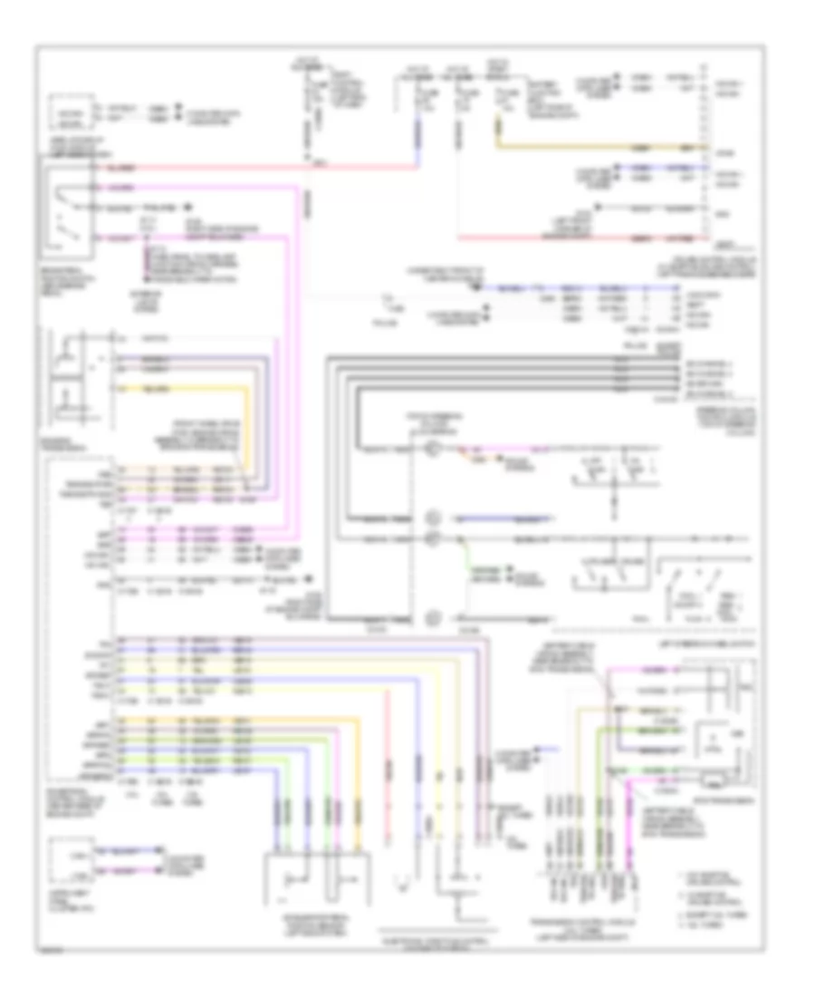
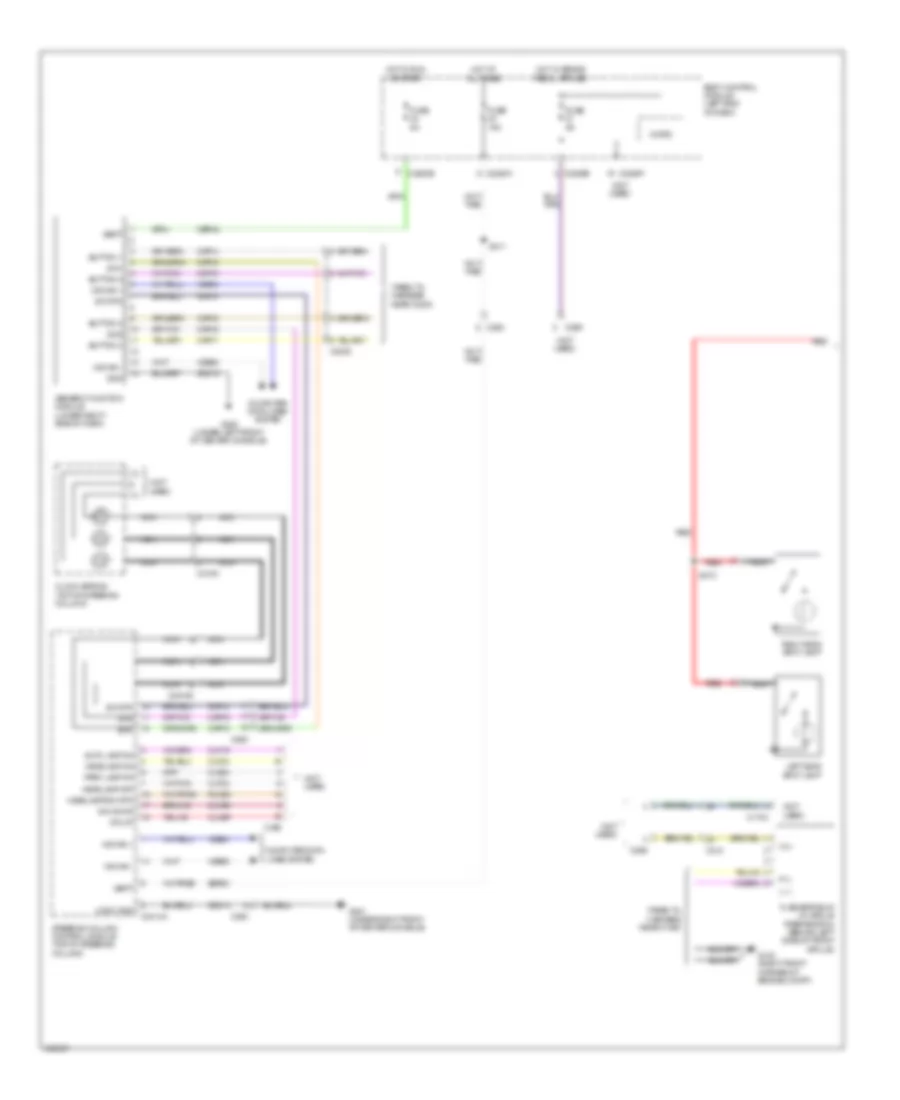
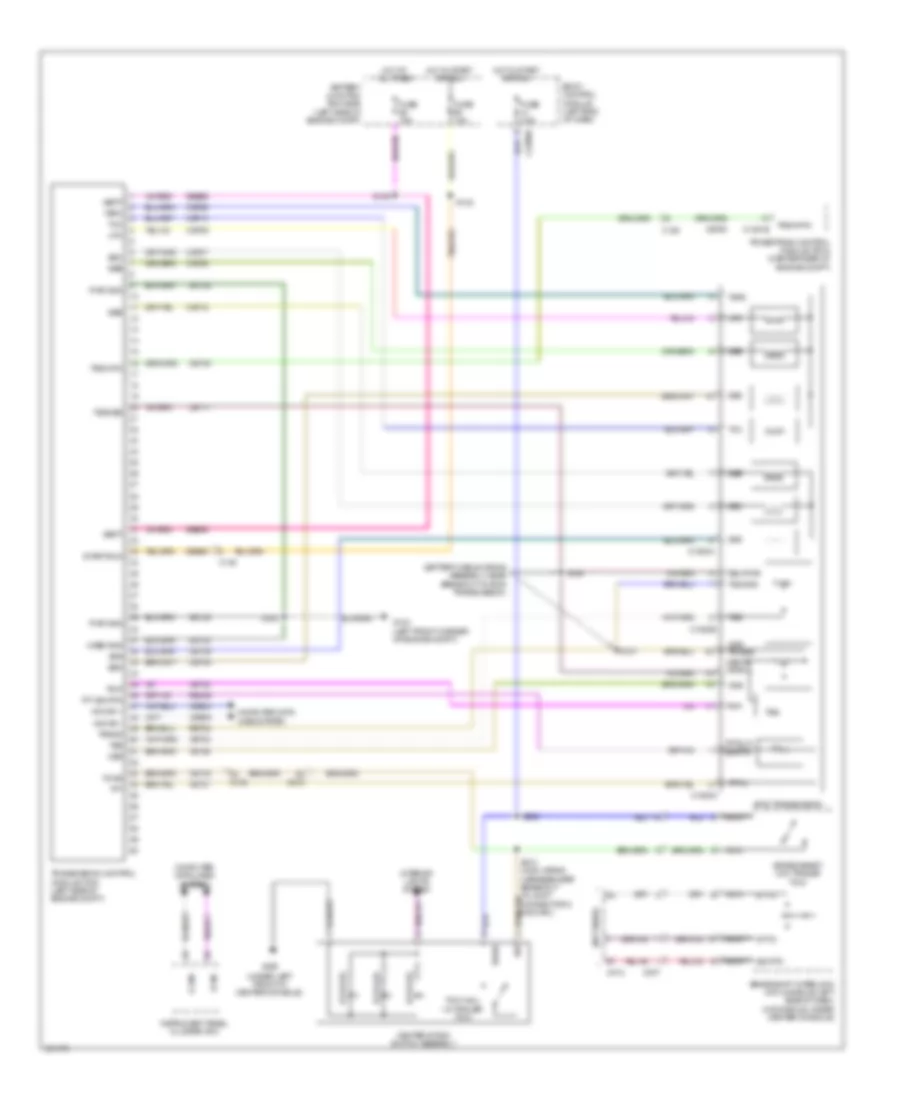
Cruise Control Wiring Diagram for Ford Explorer Police Interceptor 2013
List of elements for Cruise Control Wiring Diagram for Ford Explorer Police Interceptor 2013:
- (battery cable
- (front wheel drive
- (fwd) engine wiring assembly, in breakout to 6f50/6f55 transmission)
- (top of steering column) clockspring
- (under right front of center console) g201
- 2.0l turbo
- 3.5l
- 3.5l turbo
- 6f35 transmission
- 6f50/6f55 transmission
- A/d channel 2
- A/d channel 3
- A/d channel 4
- A/d return
- Accelerator pedal position sensor (left side of dash)
- App1
- App2
- Apprtn
- Apprtn2
- Appverf2
- Appvref
- Battery junction box (left side of engine compt)
- Body control module (left end of dash)
- Bpp
- Bps
- Brake pedal position switch (above brake pedal)
- C1381b
- C1381e
- C1520a
- C1520b
- C1551b
- C1551e
- C1609a
- C1609b
- C175b
- C175e
- C175t
- C218b
- C218c
- C2280a
- C2414a
- C2414d
- C263
- Cbb91
- Ccb08
- Ce412
- Ce426
- Ces09
- Cncl
- Computer data lines system
- Cruise +
- Cruise -
- Cruise control
- Cruise control module (w/ adaptive cruise control) (left front of engine compt)
- Electronic throttle control (on throttle body)
- Etcref
- Etcrtn
- Except 3.5l turbo
- Except police
- Exterior lights system
- Fuse 10a
- Fuse 15a
- Fuse 5a
- G103 (left front corner of engine compt)
- G106 (right side of engine compt bulkhead)
- Gap+
- Gap-
- Gd113
- Gd120
- Gd214
- Gnd
- Head up display (hud) module (left side of dash)
- Hot at all times
- Hot in start or run
- Hs can +
- Hs can -
- Hs can+
- Hs can-
- I can +
- I can -
- Instrument panel cluster (ipc)
- Le111
- Le134
- Le136
- Le137
- Left steering wheel switch
- Logic gnd
- Nca
- Off
- On/off
- Oss
- Police
- Powertrain control module (center rear of engine compt)
- Re134
- Re136
- Re137
- Res
- Res/ cncl
- Ret04
- Ret24
- Ret33
- S106
- S107
- S112 (dash panel to headlamp junction wiring harness, near breakout to windshield wiper motor)
- S114 (3.5l)
- S116
- S159
- S211
- Sbb79
- Sbp23
- Sound systems
- Steering column control module (top of steering column)
- Tacm+
- Tacm-
- Tp1
- Tp2
- Tr gnd tss/oss/
- Tr pwr tss/oss/
- Tr-p
- Transmission control module (2.0l turbo) (left side of engine compt)
- Trs
- Tss
- Tss/oss/tr gnd
- Tss/oss/vpwr
- Vbatt
- Vdb04
- Vdb05
- Vdbo4
- Vdbo5
- Ve701
- Ve702
- Ve818
- Ve819
- Vet26
- Vet32
- Vet333
- Vpwr
- W/ adaptive cruise control
- W/o adaptive
- Wiring assembly, near breakout to 6f35 transmission)
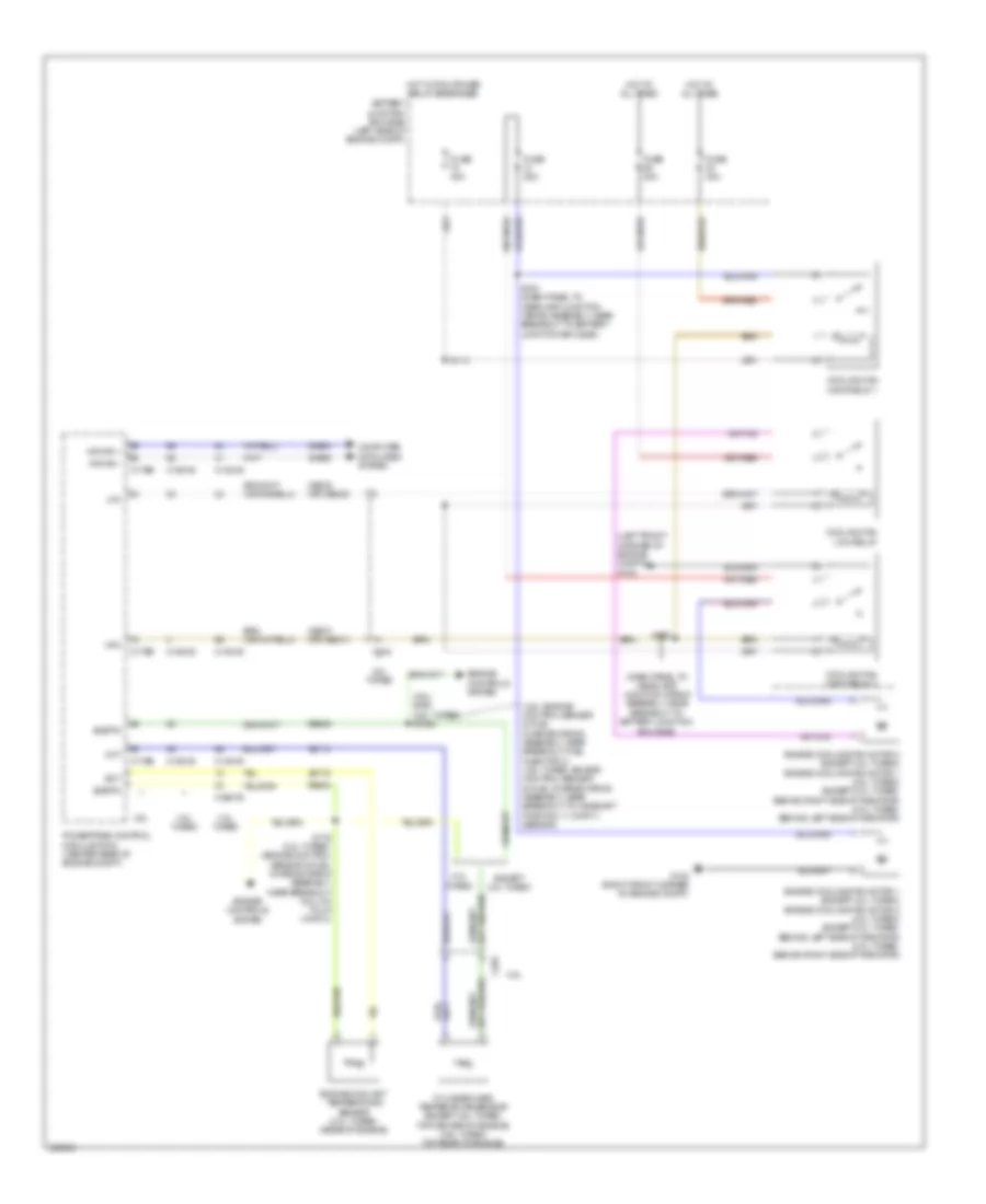
DEFOGGERS
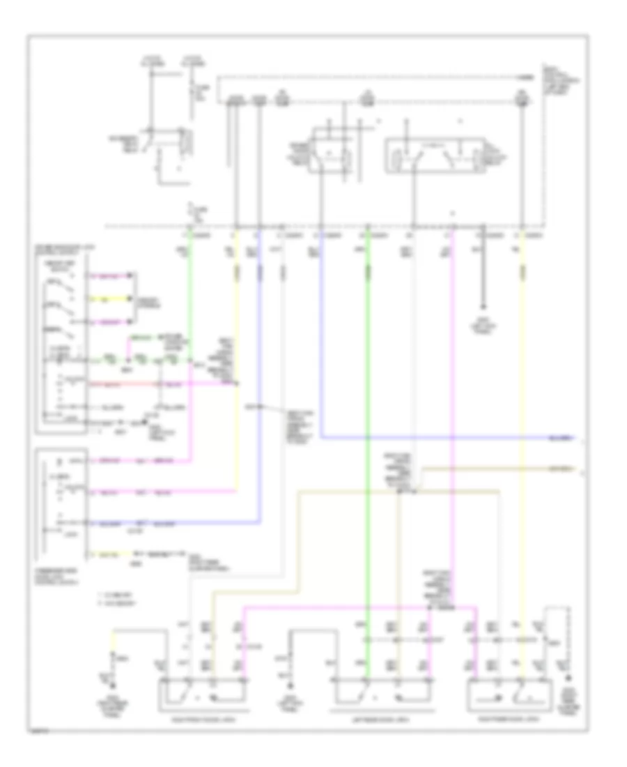
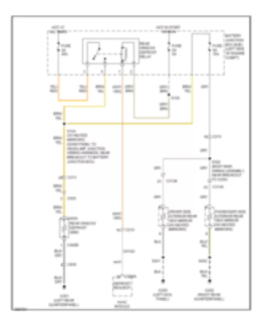
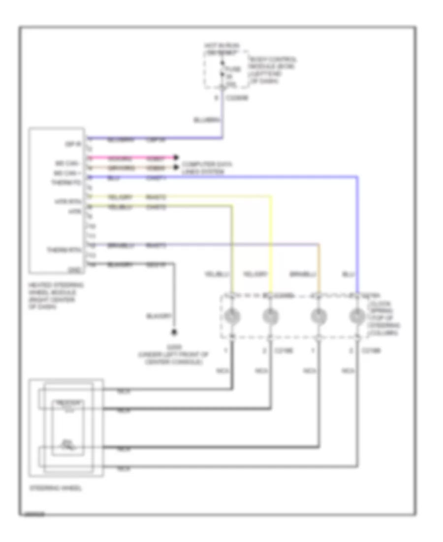
Defoggers Wiring Diagram for Ford Explorer Police Interceptor 2013
List of elements for Defoggers Wiring Diagram for Ford Explorer Police Interceptor 2013:
- Battery junction box (bjb) (left side of engine compt)
- C212
- C213
- C228a
- C3138
- C3139
- C402a
- C402b
- C935
- Ch122
- Defrost request
- Driver side exterior rear view mirror (w/ heated mirrors)
- Fuse 15a
- Fuse 40a
- Fuse 5a
- G300 (left kick panel)
- G301 (left rear quarterpanel)
- G302 (right rear quarterpanel)
- Hot at all times
- Hot in start or run
- Hvac module
- Passenger side exterior rear view mirror (w/ heated mirrors)
- Rear window defrost grid
- Rear window defrost relay
- S124 (w/ heated mirrors) (dash panel to headlamp junction wiring harness, near breakout to battery junction box)
- S125
- S501
- S602
- Wiring assembly, near breakout to g300)
ELECTRONIC POWER STEERING
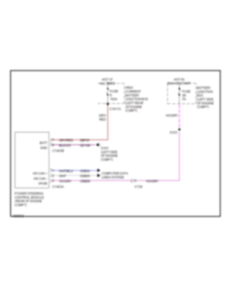
Electronic Power Steering Wiring Diagram for Ford Explorer Police Interceptor 2013
List of elements for Electronic Power Steering Wiring Diagram for Ford Explorer Police Interceptor 2013:
- Batt
- Battery junction box (left side of engine compt)
- C139
- C1463a
- C1463b
- C1617a
- Cbb89
- Computer data lines system
- Fuse 5a
- Fuse e 100a
- G101 (left side of engine compt)
- Gd108
- Gnd
- High current battery junction box (left rear of engine compt)
- Hot at all times
- Hot in run or start
- Hs can +
- Hs can -
- Power steering control module (rear of engine compt)
- S123
- Sbf05
- Vdb04
- Vdb05
- Vpwr
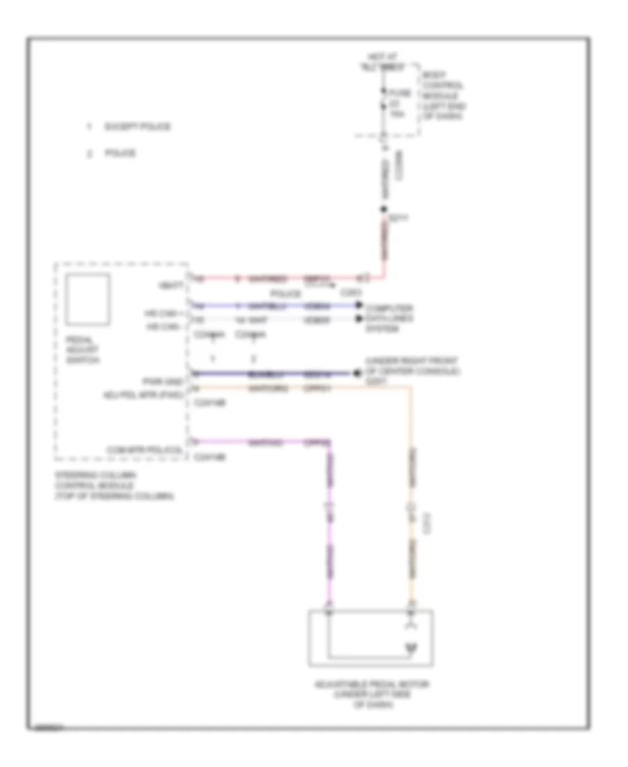
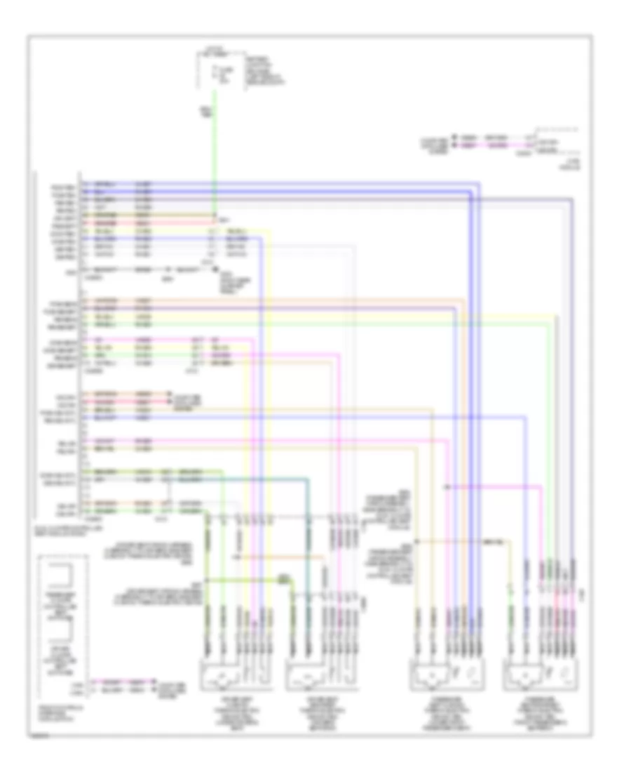
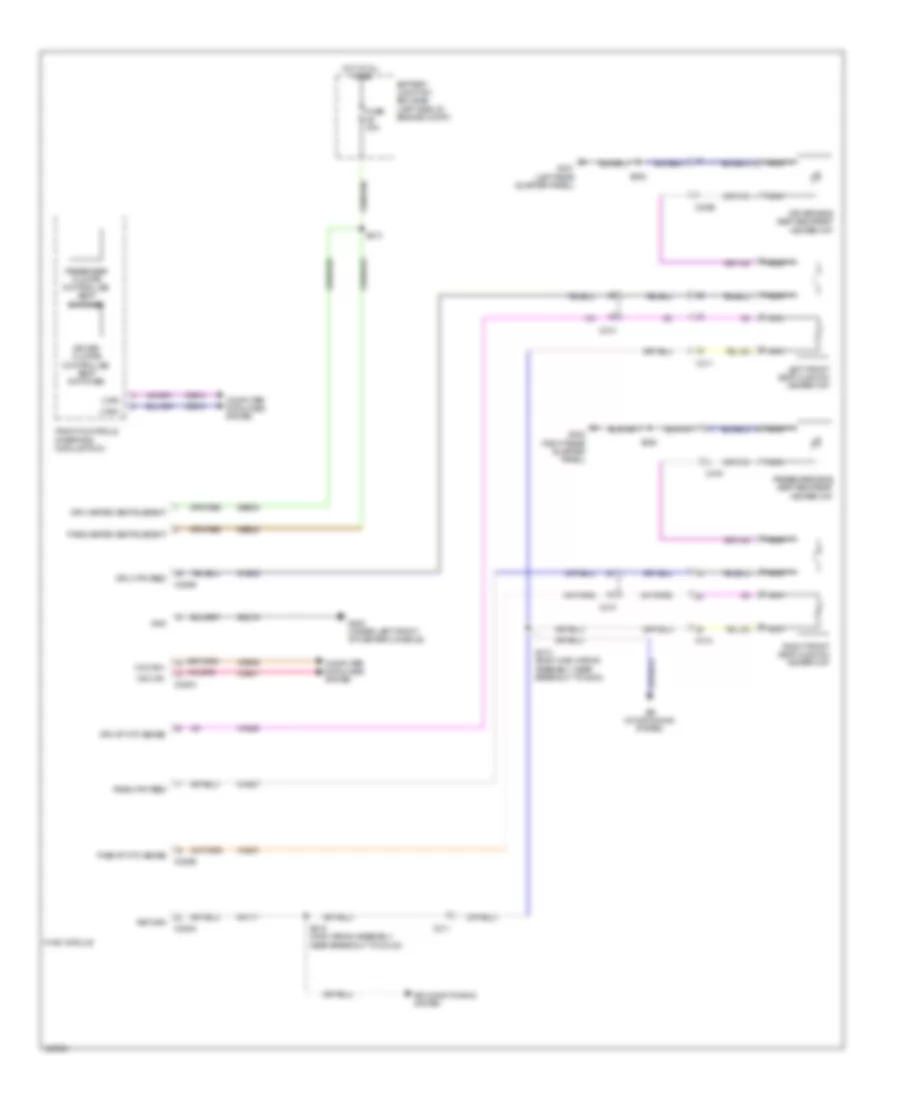
Power Steering Column Wiring Diagram for Ford Explorer Police Interceptor 2013
List of elements for Power Steering Column Wiring Diagram for Ford Explorer Police Interceptor 2013:
- (main wiring assembly, near breakout to instrument panel cluster (ipc)) s241
- (not used)
- (not used) c263
- A/d channel 1
- A/d channel 2
- A/d channel 3
- A/d channel 4
- A/d return
- Adj pdl mtr (fwd)
- Adjustable pedal motor (under left side of dash)
- Adjustable steering column telescope motor
- Adjustable steering column tilt motor (in steering column)
- Auto lamp on
- Body control module (left end of dash)
- Bps
- C212
- C218b
- C218c
- C2280a
- C2414a
- C2414b
- C2414c
- C2414d
- Cap18
- Cap19
- Cet42
- Cet43
- Clf19
- Clf23
- Clf24
- Cln55
- Cln56
- Clockspring (top of steering column)
- Cls34
- Computer data lines system
- Cpp01
- Cpp04
- Cpp05
- Cpp22
- Crh04
- Cruise control system
- Crw15
- Dim down
- Dim up
- Except police
- Frt wiper hi
- Fuse 15a
- G201 (under right front of center console)
- Gd214
- Generic function module (gem) (lower right side of dash)
- Head lamp off
- Head lamp on
- Head lamp/dim rtn
- Horn
- Horn rly ctrl
- Horns system
- Hot at all times
- Hs can +
- Hs can -
- Lin
- Logic gnd
- Lpp06
- Memory systems
- Mtr com
- Multi-function switch
- Nca
- Park lamp on
- Pdl hall sns sig
- Pedal adjust switch
- Police
- Pwr gnd
- Rap18
- Res09
- Rln29
- Rpp06
- S205
- S211
- S242 (main wiring assembly, near breakout to instrument panel cluster (ipc))
- Sbp23
- Sbp24
- Seats & memory systems
- Shift down
- Shift up
- Sns rtn
- Sound & navigation systems
- Steering column adjust switch
- Steering column control module (top of steering column)
- Sw 1
- Sw 2
- Sw rtn
- Tel mtr +/-
- Tel sns +
- Tilt mtr +/-
- Tilt sns +
- Transmissions system
- Vbatt
- Vdb04
- Vdb05
- Vdn05
- Vpp08
- Vpp17
- Wiper/washer system
ENGINE PERFORMANCE
2.0L TURBO
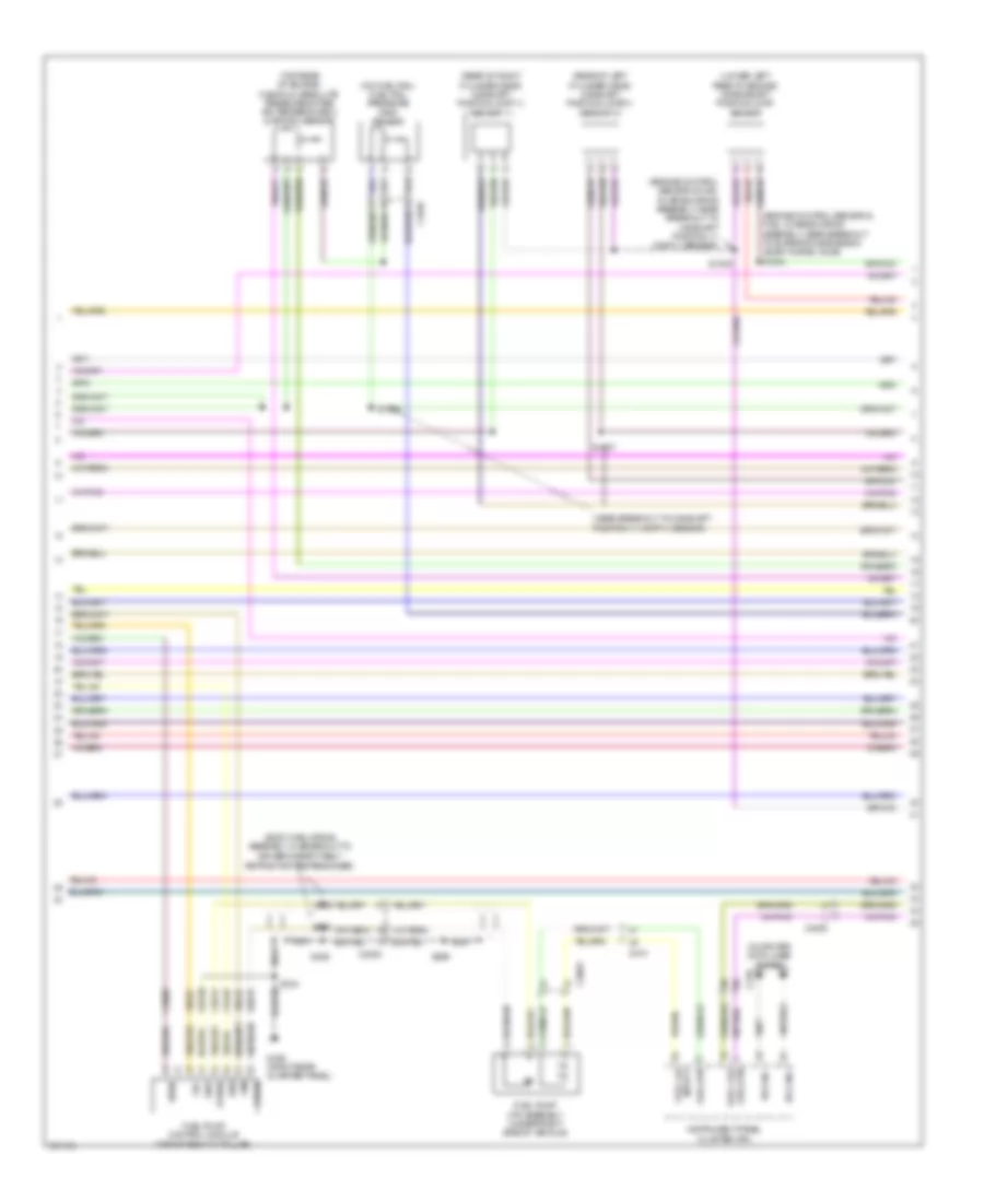
2.0L Turbo, Engine Performance Wiring Diagram (1 of 6) for Ford Explorer Police Interceptor 2013
List of elements for 2.0L Turbo, Engine Performance Wiring Diagram (1 of 6) for Ford Explorer Police Interceptor 2013:
- 7.5a
- A/c clutch relay
- Aat
- Accelerator pedal position (app) sensor (left side of dash)
- Accr
- Acpt
- Air conditioning system
- App 1
- App2
- Apprtn 1
- Apprtn2
- Appvref 1
- Appvref2
- Battery junction box (bjb) (left side of engine compt)
- Bcs2 alt
- Bpp
- Bps
- C1381b
- C139
- C140
- C213
- C2142
- C3053
- Canv
- Cbb69
- Cbb90
- Ccb08
- Cdc12
- Cdc15
- Cdc35
- Ce114
- Ce233
- Ce237
- Ce336
- Ce436
- Ces09
- Cet40
- Ch302
- Computer data lines system
- Cooling fans system
- Evaporative emission canister vent valve (under right side of vehicle)
- Externally controlled variable displacement compressor (evdc) (front right of engine compt)
- Fcv
- Fpc
- Fpm
- Fuse
- Fuse 10a
- Fuse 20a
- G106 (right side of engine compt bulkhead)
- Gd113
- Genmon
- Ho2s12
- Hot at all times
- Hot in start or run
- Hs can+
- Hs can-
- Htr12
- Isp-r
- Le136
- Le137
- Le230
- Le424
- Pcm power relay
- Pcm-wake
- Pcmrc
- Powertrain control module (pcm) (center rear of engine compt)
- Pwrgnd
- Re136
- Re137
- Re407
- S113
- S115
- S116
- S117
- S132
- Sigrtn
- Smc
- Smcs
- Start
- Starting/charging system
- Trailer brake control module connector
- Transmissions system
- Trsw-pn
- Vdb04
- Vdb05
- Vdc61
- Ve225
- Ve518
- Ve701
- Ve702
- Ve731
- Vec03
- Vh407
- Vh433
- Vpwr
- Vref
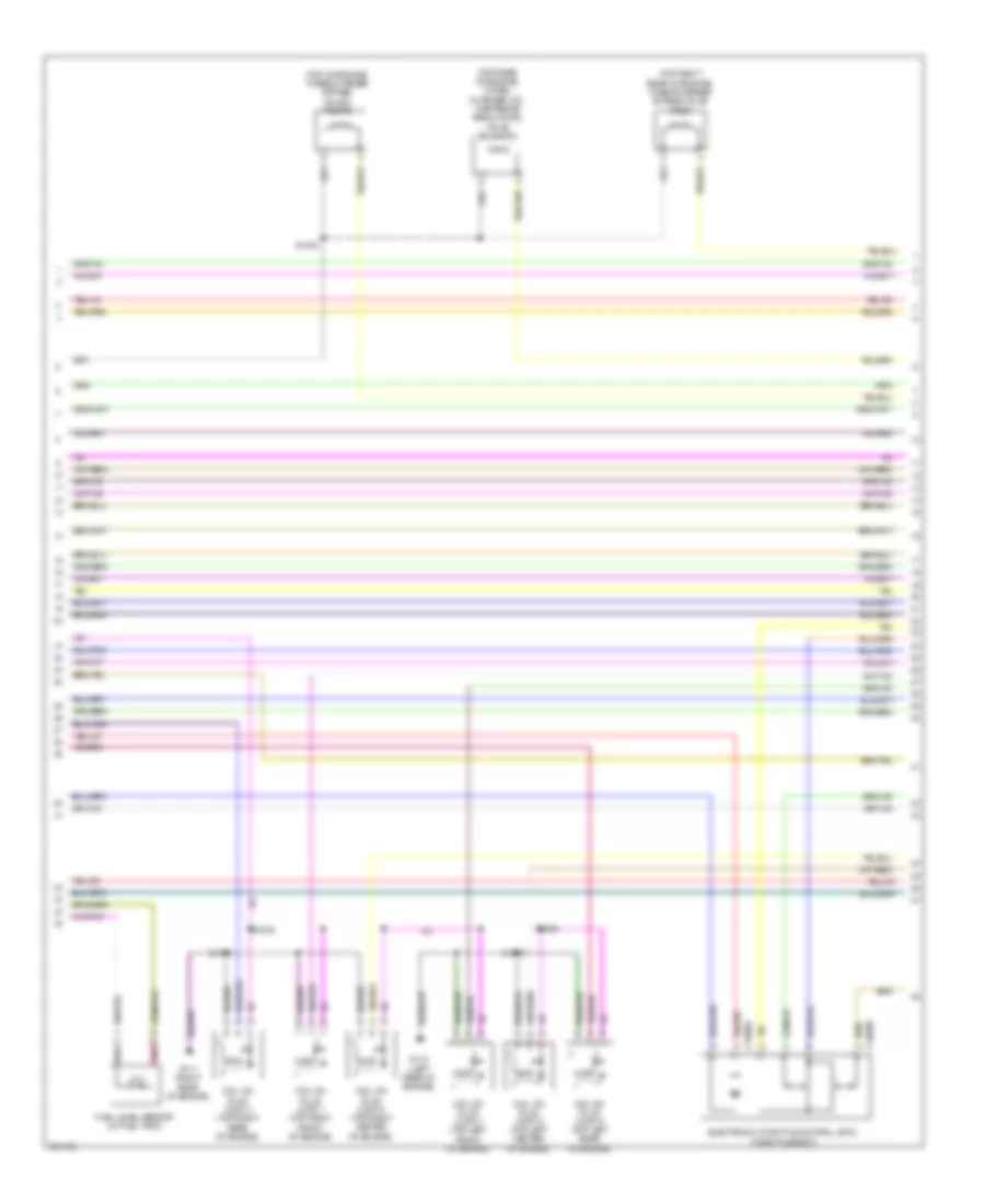
2.0L Turbo, Engine Performance Wiring Diagram (2 of 6) for Ford Explorer Police Interceptor 2013
List of elements for 2.0L Turbo, Engine Performance Wiring Diagram (2 of 6) for Ford Explorer Police Interceptor 2013:
- (at generator) generator current sensor
- (behind left side of grille) ambient air temperature (aat) sensor
- (dash panel to headlamp junction wiring assembly, near breakout to windshield wiper motor) s143
- (dash panel to headlamp junction wiring harness, near breakout to windshield wiper motor) s112
- (fuel tank jumper wiring assembly, in breakout to c3123) s398
- (fuel tank jumper wiring assembly, near breakout to c3270) s397
- (left front side of engine compt) turbocharger boost pressure/charge air coolant temperature (tcbp/cact) sensor
- (right front corner of engine compt) a/c pressure transducer
- (under right side of vehicle) fuel pressure sensor
- (under right side of vehicle) fuel tank pressure (ftp) sensor
- Bpp
- Brake pedal position (bpp) switch (above brake pedal)
- C139
- C140
- C212
- C213
- C2153c
- C3053
- Ccb08
- G106 (right side of engine compt bulkhead)
- Remote function actuator module (w/ intelligent access) (under glove box)
- S172
- S200 (w/ intelligent access) (light sensor extension wiring assembly, near breakout to autolamp/sunload sensor)
- Turbocharger bypass valve (tcby) (top of engine)
- Turbocharger wastegate regulating valve solenoid (right side of engine)
2.0L Turbo, Engine Performance Wiring Diagram (3 of 6) for Ford Explorer Police Interceptor 2013
List of elements for 2.0L Turbo, Engine Performance Wiring Diagram (3 of 6) for Ford Explorer Police Interceptor 2013:
- (right rear of engine) evaporative emission (evap) purge valve
- (right side of engine, on exhaust) heated oxygen sensor (ho2s) 12
- (right side of engine, on exhaust) universal heated oxygen sensor (ho2s) 11
- (top front of engine) variable camshaft timing 11 (vct11) solenoid
- (top front of engine) variable camshaft timing 12 (vct12) solenoid
- Air conditioning system
- C1381e
- C139
- C140
- Cdc10
- Ce113
- Ce205
- Ce207
- Ce235
- Ce303
- Ce304
- Ce305
- Ce306
- Ce412
- Ce421
- Ce422
- Cec01
- Cmp11
- Cmp12
- Cooling fans system
- Cop1a
- Cop2d
- Cop3b
- Cop4c
- Evapcp
- Gencom
- Hfc
- Inj1
- Inj3
- Ks1+
- Ks2+
- Le329
- Le451
- Map
- Nca
- Powertrain control module (pcm) (center rear of engine compt)
- S134
- S173
- Starting/charging system
- Tacm+
- Tcwrvs
- Tp2
- Uo2s11
- Uo2shrt11
- Uo2spct11
- Vacc
- Vct11
- Vct12
- Ve462
- Ve706
- Ve707
- Ve801
- Ve802
- Ve819
- Ve824
- Ve826
2.0L Turbo, Engine Performance Wiring Diagram (4 of 6) for Ford Explorer Police Interceptor 2013
List of elements for 2.0L Turbo, Engine Performance Wiring Diagram (4 of 6) for Ford Explorer Police Interceptor 2013:
- (in breakout to
- (left side of dash) (w/o ia) passive anti-theft transceiver
- (not used)
- (top left side of engine)
- Battery junction box (bjb) (left side of engine compt)
- Body control module (left end of dash)
- C210
- C212
- C213
- C2280b
- C2280f
- C3053
- C310b
- Ce515
- Ce608
- Coil on plug (cop) 1
- Coil on plug (cop) 2
- Coil on plug (cop) 3
- Coil on plug (cop) 4
- Computer data lines system
- Cr167
- Driver's safety belt retractor pretensioner)
- Ens
- Fp pwr
- Fp rtn
- Fpc
- Fpm
- Fuel
- Fuel lvl
- Fuel pump (fet)
- Fuel pump (fp) relay
- Fuel pump assembly (under right side of vehicle)
- Fuel pump control module (top of right "c" pillar)
- Fuel vpwr
- Fuse 10a
- Fuse 30a
- Fuse 5a
- G110 (right rear side of engine)
- G302 (right rear quarter panel)
- Gd348
- Gnd
- Hot at all times
- Hs can +
- Hs can -
- Input 1
- Instrument panel cluster (ipc)
- Micro
- Ms can +
- Ms can -
- Nca
- Pcm wake up (fet)
- Re515
- Red
- Restraints control module (rcm) (under center console)
- Return
- S111 (dash panel to headlamp junction wiring harness, near breakout to windshield wiper motor)
- S129
- S174
- S175
- S329
- S333
- S334
- S335
- S336
- S396
- Vdb06
- Vdb07
- Ve225
- Ve518
2.0L Turbo, Engine Performance Wiring Diagram (5 of 6) for Ford Explorer Police Interceptor 2013
List of elements for 2.0L Turbo, Engine Performance Wiring Diagram (5 of 6) for Ford Explorer Police Interceptor 2013:
- (cop) 2)
- (engine control sensor & fuel charge wiring assembly, near breakout coil on plug
- (engine control sensor & fuel charge wiring assembly, near breakout powertrain control module
- (engine control sensor & fuel charge wiring assembly, near breakout to powertrain control module (pcm))
- (left front of engine) manifold absolute pressure (map) sensor
- (left rear of engine) camshaft position (cmp) sensor 11
- (lower right side of engine) wastegate vacuum sensor
- (near breakout coil on plug 3) s177
- (on fuel rail) fuel rail pressure (frp) sensor
- (pcm)
- (rear of engine) engine coolant temperature (ect) sensor
- (right rear of engine) camshaft position (cmp) sensor 12
- (right side of engine) crankshaft position (ckp) sensor
- (top left side of engine )
- C1033
- Cylinder head temperature (cht) sensor
- Electronic throttle control (etc) (throttle body)
- Fuel injector
- S170
- S171
- S176
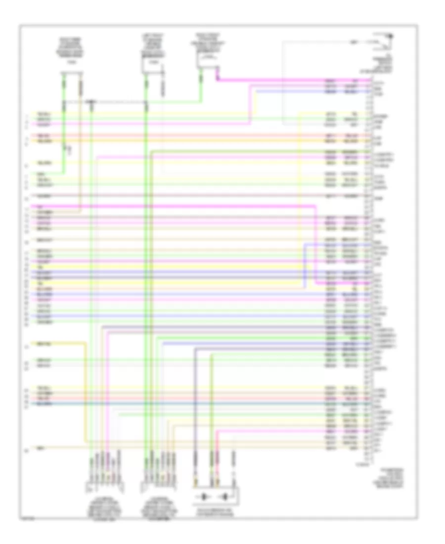
2.0L Turbo, Engine Performance Wiring Diagram (6 of 6) for Ford Explorer Police Interceptor 2013
List of elements for 2.0L Turbo, Engine Performance Wiring Diagram (6 of 6) for Ford Explorer Police Interceptor 2013:
- (not used) c140
- C1033
- C1381e
- C140
- Cact
- Ce206
- Ce208
- Ce226
- Ce426
- Cec02
- Cht
- Ckp
- Cmc24
- Cooling fans system
- Ect
- Etcref
- Etcrtn
- Flp
- Frp
- Ftp
- Fuel injection pump (right rear of engine)
- Fvr
- Fvrrtn
- Iat
- Inj1rtn
- Inj2
- Inj2rtn
- Inj3rtn
- Inj4
- Inj4rtn
- Intake air temperature (iat) sensor (left front of engine compt)
- Knock sensor 1 (ks1) (left front of engine)
- Knock sensor 2 (ks2) (left rear of engine)
- Ks1-
- Ks2-
- Le134
- Le238
- Le423
- Le448
- Le452
- Le458
- Lfc
- Lin
- Oil pressure switch (left side of engine block)
- Ops
- Powertrain control module (pcm) (center rear of engine compt)
- Re134
- Re205
- Re206
- Re207
- Re208
- Re226
- Re320
- Re323
- Re324
- Re405
- Re454
- Sigrtn
- Tacm-
- Tcbp
- Tcby
- Tp1
- Uo2sgref11
- Uo2spc11
- Vdn08
- Ve711
- Ve712
- Ve716
- Ve727
- Ve740
- Ve803
- Ve804
- Ve818
- Ve821
- Ve836
- Ve922
- Vref
- Wvs
3.5L
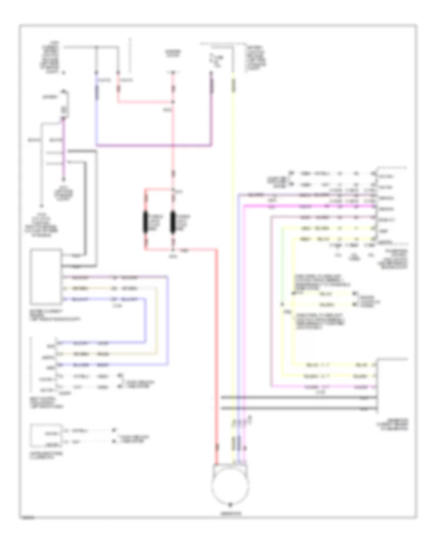
3.5L, Engine Performance Wiring Diagram (1 of 6) for Ford Explorer Police Interceptor 2013
List of elements for 3.5L, Engine Performance Wiring Diagram (1 of 6) for Ford Explorer Police Interceptor 2013:
- (at generator) generator current sensor
- (dash panel to headlamp junction wiring assembly, near breakout to battery junction box (bjb)) s121
- (dash panel to headlamp junction wiring assembly, near breakout to windshield wiper motor) s143
- (left side of dash) accelerator pedal position sensor
- (under right side of vehicle) evaporative emission canister vent valve
- A/c pressure transducer (right front corner of engine compt)
- Aat
- Accr
- Acpt
- Air conditioning system
- App1
- App2
- Apprtn 1
- Apprtn2
- Appvref 1
- Appvref2
- Awdc
- Awdm
- Battery junction box (left side of engine compt)
- Bcs2 alt
- Bpp
- Bps
- C139
- C175b
- C212
- C213
- C2238
- C3053
- Canv
- Case gnd
- Cbb69
- Cbb90
- Ccb08
- Cdc10
- Cdc12
- Cdc15
- Cdc35
- Ce114
- Ce237
- Ce336
- Ce436
- Ce608
- Cec07
- Cec08
- Ces09
- Cet42
- Cet43
- Ch302
- Computer data lines system
- Cooling fans system
- Digital
- Fpc
- Fpm
- Ftp
- Fuel tank pressure sensor (under right side of vehicle)
- Fuse 10a
- G106 (right side of engine compt bulkhead)
- Gd113
- Gencom
- Genmon
- Hfc
- Hot in start or run
- Hs can +
- Hs can -
- Iat
- Injpwrm
- Isp r
- Kapwr
- Le136
- Le137
- Le230
- Le424
- Lfc
- Maf
- Mass air flow/ intake air temperature sensor (left front of engine compt)
- Pcm wake
- Pcmrc
- Police
- Powertrain control module (center rear of engine compt)
- Pwr gnd
- Re136
- Re137
- Re320
- Re407
- S114
- Sbb86
- Sig rtn
- Sigrtn
- Smc
- Smcs
- Sst-d
- Sst-u
- Start
- Starting/charging system
- Tapped to harness near c2238
- Transmissions system
- Vcf34
- Vcf35
- Vdb04
- Vdb05
- Vdc61
- Ve225
- Ve518
- Ve701
- Ve702
- Ve740
- Ve807
- Ve922
- Vh407
- Vh433
- Vmc05
- Vpwr
- Vref
- Vref 5v
- Vso
3.5L, Engine Performance Wiring Diagram (2 of 6) for Ford Explorer Police Interceptor 2013
List of elements for 3.5L, Engine Performance Wiring Diagram (2 of 6) for Ford Explorer Police Interceptor 2013:
- (behind left side of grille) ambient air temperature sensor
- (body main wiring assembly, in breakout to driver's safety belt retractor pretensioner)
- (main wiring assembly, near breakout to c2123)
- (main wiring assembly, near breakout to defrost/panel/floor mode door actuator)
- (main wiring harness, near near breakout to hs-can
- (on throttle body) electronic throttle control
- (under center console) brake shift interlock
- (w/console: under center console) (w/o console: left side of dash) center stack switch assembly
- Body control module (left end of dash)
- C140
- C212
- C213
- C2280b
- C237
- C263
- C3053
- C310b
- Ce515
- Ce608
- Computer data lines system
- Cr167
- Ens
- Fpc
- Fpm
- Fppwr
- Fprtn
- Fuel pump assembly (under right side of vehicle)
- Fuel pump control module (top of right "c" pillar)
- Fuse 5a
- Fuse 7.5a
- G302 (right rear quarter panel)
- Gd348
- Gnd
- Hot in start or run
- Hs can +
- Hs can -
- Instrument cluster system
- Instrument panel cluster (ipc)
- Joint connector 6)
- Lower gear selector switch
- Nca
- Re515
- Restraints control module (under center console)
- S202
- S210
- S217
- S244 (w/ paddle shift)
- S245 (w/ paddle shift)
- S329
- S333 (body main wiring assembly, in breakout to driver's safety belt retractor pretensioner)
- S334
- S335
- S336
- S396
- Sst-d
- Sst-u
- Tow haul
- Transmissions system
- Ve225
- Ve518
- Vpwr fuel
- W/ column shifter
- W/ floor shifter
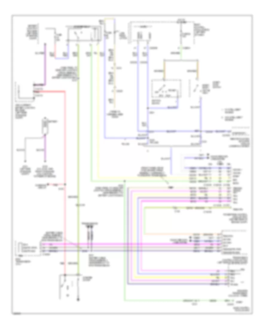
3.5L, Engine Performance Wiring Diagram (3 of 6) for Ford Explorer Police Interceptor 2013
List of elements for 3.5L, Engine Performance Wiring Diagram (3 of 6) for Ford Explorer Police Interceptor 2013:
- (center rear of engine compt) (w/ power takeoff unit) power takeoff sensor
- (dash panel to headlamp junction wiring assembly, near breakout to battery junction box (bjb)) s120
- Battery junction box (left side of engine compt)
- C139
- C140
- C175t
- Ce233
- Ce234
- Cet05
- Cet06
- Cet07
- Cet08
- Cet09
- Cet10
- Cet19
- Cet25
- Cet34
- Fuel pump (fp) relay
- Fuse 10a
- Fuse 20a
- Fuse 30a
- Fuse 7.5a
- Heated oxygen sensor 12 (right exhaust pipe, after catalytic converter)
- Ho2s12
- Ho2s22
- Hot at all times
- Htr12
- Htr22
- Le111
- Lpc
- Nca
- Oss
- Pcm power relay
- Re406
- Red
- Ret04
- Ret24
- Ret33
- S115
- S117
- S129
- S134
- Sigrtn
- Ssa
- Ssb
- Ssc
- Ssd
- Sse
- Tcc
- Tft
- Tows
- Tr 1
- Tr 2
- Tr 3
- Tr 4
- Tspc powertrain control module (center rear of engine compt)
- Tss
- Tss/oss/tr gnd
- Ve731
- Ve733
- Vet27
- Vet29
- Vet30
- Vet31
- Vet32
- Vref
3.5L, Engine Performance Wiring Diagram (4 of 6) for Ford Explorer Police Interceptor 2013
List of elements for 3.5L, Engine Performance Wiring Diagram (4 of 6) for Ford Explorer Police Interceptor 2013:
- (dash panel to headlamp junction wiring assembly, near breakout to windshield wiper motor)
- (dash panel to headlamp junction wiring assembly, near breakout to windshield wiper motor) s111
- (front wheel drive (fwd) engine wiring assembly, in breakout to 6f50/6f55 transmission) s159
- (left side of dash) (w/o intelligent access)
- (not used)
- (top center of engine) cylinder head temperature sensor
- (under glove box) (w/ intelligent access) remote function actuator module
- 6f50/6f55 transmission
- Body control module (left end of dash)
- Bpp
- Brake pedal position switch (above brake pedal)
- C192
- C212
- C2153c
- C2280b
- C2280f
- C299
- Ccb08
- Cet05
- Cet06
- Cet07
- Cet08
- Cet09
- Cet10
- Cet19
- Cet25
- Computer data lines system
- Except police
- Fuel pump (fet)
- Fuse 10a
- Fuse 5a
- G106 (right side of engine compt bulkhead)
- Heated oxygen sensor 22 (left exhaust pipe, after catalytic converter)
- Hot at all times
- Le111
- Lpc
- Micro
- Ms can +
- Ms can -
- Nca
- Oss
- Passive anti-theft transceiver
- Pcm wake up (fet)
- Police
- Re406
- Ret04
- Ret24
- Ret33
- S112
- S114
- S156 (engine control sensor & fuel charge wiring assembly, near breakout to fuel injector 3)
- Ssa
- Ssb
- Ssc
- Ssd
- Sse
- Tcc
- Tft
- Tft sig rtn
- Tr 1
- Tr 2
- Tr 3
- Tr 4
- Tr gnd
- Trailer brake control module connector
- Trs
- Tspc
- Tss
- Tss/oss gnd
- Tss/oss vpwr
- Universal heated oxygen sensor 11 (right exhaust pipe, before catalytic converter)
- Universal heated oxygen sensor 21 (left exhaust pipe, before catalytic converter)
- Vdb06
- Vdb07
- Vet27
- Vet29
- Vet30
- Vet31
- Vet32
3.5L, Engine Performance Wiring Diagram (5 of 6) for Ford Explorer Police Interceptor 2013
List of elements for 3.5L, Engine Performance Wiring Diagram (5 of 6) for Ford Explorer Police Interceptor 2013:
- (left front of engine) vct solenoid 21
- (left front of engine) vct solenoid 22
- (right front of engine) vct solenoid 11
- (right front of engine) vct solenoid 12
- (right rear of engine) evaporative emission purge valve
- (top rear of engine) knock sensor
- C140
- Coil on plug (cop) 1 (top right front of engine)
- Coil on plug (cop) 2 (top right center of engine)
- Coil on plug (cop) 3 (top right rear of engine)
- Coil on plug (cop) 4 (top left front of engine)
- Coil on plug (cop) 5 (top left center of engine)
- Coil on plug (cop) 6 (top left rear of engine)
- Fuel injector 1 (top right front of engine)
- Fuel injector 2 (top right center of engine)
- Fuel injector 3 (top right rear of engine)
- Fuel injector 4 (top left front of engine)
- Fuel injector 5 (top left center of engine)
- Fuel injector 6 (top left rear of engine)
- S154
- S155
- S157
- S158
- Tan
3.5L, Engine Performance Wiring Diagram (6 of 6) for Ford Explorer Police Interceptor 2013
List of elements for 3.5L, Engine Performance Wiring Diagram (6 of 6) for Ford Explorer Police Interceptor 2013:
- (engine control sensor & fuel charge wiring assembly, near breakout powertrain control module (pcm))
- (engine control sensor & fuel charge wiring assembly, near breakout to powertrain control module)
- (lower right rear of engine) crankshaft position sensor
- (not used) c140
- (rear of left cylinder head) camshaft position sensor 21
- (rear of left cylinder head) camshaft position sensor 22
- (rear of right cylinder head) camshaft position sensor 11
- (rear of right cylinder head) camshaft position sensor 12
- Aat
- C140
- C175e
- Ce113
- Ce205
- Ce206
- Ce207
- Ce208
- Ce209
- Ce210
- Ce235
- Ce236
- Ce303
- Ce304
- Ce305
- Ce306
- Ce307
- Ce308
- Ce412
- Ce421
- Ce422
- Ce426
- Ce442
- Ce443
- Cht
- Ckp+
- Ckp-
- Cmc24
- Cmp11
- Cmp12
- Cmp21
- Cmp22
- Cop1a
- Cop2c
- Cop3e
- Cop4b
- Cop5d
- Cop6f
- De135
- Etcref
- Etcrtn
- Evapcp
- Inj 1
- Inj 2
- Inj 3
- Inj 4
- Inj 5
- Inj 6
- Instrument cluster system
- Ks1+
- Ks1-
- Ks2+
- Ks2-
- Le134
- Le448
- Le449
- Le450
- Le451
- Le452
- Le453
- Nca
- Ops
- Powertrain control module (center rear of engine compt)
- Pto
- Re134
- Re135
- Re323
- Re324
- Re405
- Re429
- S150
- S151
- S160
- Shdrtn
- Sigrtn
- Tacm+
- Tacm-
- Tp1
- Tp2
- Uo2s11
- Uo2s21
- Uo2sgref11
- Uo2sgref21
- Uo2shtr11
- Uo2shtr21
- Uo2spc11
- Uo2spc21
- Uo2spct11
- Uo2spct21
- Vct11
- Vct12
- Vct21
- Vct22
- Ve706
- Ve707
- Ve711
- Ve712
- Ve740
- Ve801
- Ve802
- Ve818
- Ve819
- Ve826
- Ve827
- Vet27
- Vrsrtn
- Vrsrtn2
3.5L TWIN TURBO
3.5L Twin Turbo, Engine Performance Wiring Diagram (1 of 7) for Ford Explorer Police Interceptor 2013
List of elements for 3.5L Twin Turbo, Engine Performance Wiring Diagram (1 of 7) for Ford Explorer Police Interceptor 2013:
- (center rear of engine compt) (w/ power takeoff unit) power takeoff sensor
- (dash panel to headlamp junction wiring assembly, near breakout to
- (dash panel to headlamp junction wiring assembly, near breakout to windshield wiper motor)
- (fuel tank jumper wiring assembly, near breakout to c3123) s398
- (fuel tank jumper wiring assembly, near breakout to c3270)
- (under right side of vehicle) fuel pressure sensor
- (under right side of vehicle) fuel tank pressure (ftp) sensor
- A/c pressure transducer (right front corner of engine compt)
- Aat
- Accelerator pedal position (app) sensor (left side of dash)
- Accr
- Acpt
- Air conditioning system
- App1
- App2
- Apprtn1
- Apprtn2
- Appvref1
- Appvref2
- Awdc
- Awdm
- Battery junction box (bjb))
- Body control module (bcm) (left end of dash)
- Bpp
- Bps
- C139
- C140
- C1551b
- C212
- C213
- C2280f
- C3053
- Cact
- Canv
- Cbb90
- Ccb08
- Cdc10
- Cdc12
- Cdc15
- Cdc35
- Ce113
- Ce114
- Ce233
- Ce234
- Ce237
- Ce336
- Ce436
- Cec07
- Cec08
- Ces09
- Ch302
- Computer data lines system
- Cooling fans system
- Evapcp
- Evdc
- Fpc
- Fpm
- Fuse 10a
- Gencom
- Generator current sensor (at generator)
- Genmon
- Heated oxygen sensor (ho2s) 12 (right exhaust pipe, after catalytic converter)
- Heated oxygen sensor (ho2s) 22 (left exhaust pipe, after catalytic converter)
- Hfc
- Ho2s12
- Ho2s22
- Hot at all times
- Hs can +
- Hs can -
- Hs can+
- Hs can-
- Htr12
- Htr22
- Isp-r
- Le136
- Le137
- Le230
- Le424
- Lfc
- Micro
- Nca
- Passive anti-theft transceiver (w/o intelligent access) (left side of dash)
- Pcm wake
- Pcm wake up (fet)
- Pcmrc
- Powertrain control module (pcm) (center rear of engine compt)
- Re136
- Re137
- Re230
- Re242
- Re249
- Re407
- Res09
- S111
- S121
- S143
- S397
- Sigrtn
- Smc
- Smcs
- Start
- Starting/ charging system
- Starting/charging system
- Vcf34
- Vcf35
- Vdb04
- Vdb05
- Ve225
- Ve462
- Ve518
- Ve701
- Ve702
- Ve731
- Ve733
- Ve751
- Vh407
- Vh433
- Vref
3.5L Twin Turbo, Engine Performance Wiring Diagram (2 of 7) for Ford Explorer Police Interceptor 2013
List of elements for 3.5L Twin Turbo, Engine Performance Wiring Diagram (2 of 7) for Ford Explorer Police Interceptor 2013:
- (dash panel to headlamp junction wiring assembly, near breakout to windshield wiper motor)
- (front right of engine compt) externally controlled variable displacement compressor (evdc)
- (under right side of vehicle) evaporative emission (evap) canister vent valve
- 7.5a
- All wheel drive (awd) relay module (left "d" pillar)
- Ambient air temperature (aat) sensor (behind left side of grille)
- Awdc
- Awdm
- Battery junction box (bjb) (left side of engine compt)
- Brake pedal position (bpp) switch (above brake pedal)
- Breakout to clockspring)
- C139
- C140
- C213
- C218a
- C218b
- C218c
- C2414a
- C3053
- Clockspring (top of steering column)
- Fuse
- Fuse 10a
- Fuse 20a
- G106 (right side of engine compt bulkhead)
- G201 (under right front of center console)
- Hot at all times
- Hot in run or start
- Interior lights system
- Left paddle shifter
- Nca
- Pcm power relay
- Pnk
- Right paddle shifter
- S112
- S113
- S117
- S134
- S197
- S294 (steering wheel jumper wiring assembly, near nca
- S296
- Steering column control module (sccm) (top of steering column) c2414d
- Turbocharger boost pressure/charge air cooler temperature (tcbp/cact) sensor (in air intake duct)
- Vcf34
- Vcf35
3.5L Twin Turbo, Engine Performance Wiring Diagram (3 of 7) for Ford Explorer Police Interceptor 2013
List of elements for 3.5L Twin Turbo, Engine Performance Wiring Diagram (3 of 7) for Ford Explorer Police Interceptor 2013:
- (left front of engine compt) intake air temperature (iat) sensor
- (main wiring assembly, near breakout to c2123)
- (main wiring assembly, near breakout to defrost/panel/floor mode door actuator)
- (not used) ce608
- (under glove box) (w/ intelligent access) remote function (rfa) actuator module
- (w/ console: under center console) (w/o console: left side of dash) brake shift interlock
- Battery junction box (bjb) (left side of engine compt)
- Bcs2 alt
- Body control module (bcm) (left end of dash)
- Bpp
- C1551b
- C1551e
- C212
- C213
- C2153c
- C2280b
- C2280f
- C237
- Cbb69
- Ccb08
- Ce205
- Ce206
- Ce207
- Ce208
- Ce209
- Ce210
- Ce226
- Ce305
- Ce308
- Ce412
- Ce426
- Cet07
- Cet25
- Cet34
- Cet42
- Cet43
- Cop3e
- Cop6f
- Flp
- Ftp
- Fuel pump (fet)
- Fuel pump relay
- Fuse 30a
- Fvr
- Fvrrtn
- G106 (right side of engine compt bulkhead)
- Gd113
- Hot at all times
- Iat
- Inj1
- Inj1rtn
- Inj2
- Inj2rtn
- Inj3
- Inj3rtn
- Inj4
- Inj4rtn
- Inj5
- Inj5rtn
- Inj6
- Inj6rtn
- Micro
- Nca
- Powertrain control module (pcm) (center rear of engine compt)
- Pto
- Pwrgnd
- Re205
- Re206
- Re207
- Re208
- Re209
- Re210
- Re226
- Red
- S115
- S116
- S120 (dash panel to headlamp junction wiring assembly, near breakout to battery junction box (bjb))
- S129
- S244
- S245
- S333 (body main wiring assembly, in breakout to driver's safety belt retractor pretensioner)
- Sbb86
- Ssc
- Sst-d
- Starting/ charging system
- Stt-u
- Tacm+
- Tacm-
- Tcbp
- Tows
- Transmissions system
- Tspc
- Vbatt
- Vdc61
- Ve740
- Ve804
- Ve830
- Ve922
- Vet27
- Vpwr
- W/ floor shifter
- W/ paddle shifter
3.5L Twin Turbo, Engine Performance Wiring Diagram (4 of 7) for Ford Explorer Police Interceptor 2013
List of elements for 3.5L Twin Turbo, Engine Performance Wiring Diagram (4 of 7) for Ford Explorer Police Interceptor 2013:
- (top rear of engine) cylinder head temperature (cht) sensor
- 6f50/6f55 transmission
- C1045
- C1046
- C310b
- Cet05
- Cet06
- Cet07
- Cet08
- Cet09
- Cet10
- Cet19
- Cet25
- Cr167
- Ens
- Fuel injection pump (left front of engine)
- Fuel injector 1 (top right front of engine)
- Fuel injector 2 (top right center of engine)
- Fuel injector 3 (top right rear of engine)
- Fuel injector 4 (top left front of engine)
- Fuel injector 5 (top left center of engine)
- Fuel injector 6 (top left rear of engine)
- Le111
- Lpc
- Oss
- Re405
- Restraints control module (rcm) (under center console)
- Ret04
- Ret24
- Ret33
- S159 (in breakout to 6f50/6f55 transmission)
- Ssa
- Ssb
- Ssc
- Ssd
- Sse
- Tcc
- Tft
- Tr gnd
- Tr-1
- Tr-2
- Tr-3
- Tr-4
- Trs
- Tspc
- Tss
- Tss/oss gnd
- Tss/oss vpwr
- Vet27
- Vet29
- Vet30
- Vet31
- Vet32
3.5L Twin Turbo, Engine Performance Wiring Diagram (5 of 7) for Ford Explorer Police Interceptor 2013
List of elements for 3.5L Twin Turbo, Engine Performance Wiring Diagram (5 of 7) for Ford Explorer Police Interceptor 2013:
- (body main wiring assembly, in breakout to
- (engine control sensor & fuel charge wiring assembly, near breakout to camshaft position 11 (cmp11) sensor)
- (engine control sensor & fuel charge wiring assembly, near breakout to evaporative emission (evap) purge valve) s1004
- (lower left rear of engine) crankshaft position (ckp) sensor
- (near breakout to camshaft
- (on fuel rail) fuel rail pressure (frp) sensor
- (rear of left cylinder head) camshaft position (cmp21) sensor 21
- (rear of right cylinder head) camshaft position (cmp11) sensor 11
- (top rear of engine) manifold absolute pressure/intake air temperature 2 (map/iat2) sensor
- C1046
- C210
- C3053
- Ce515
- Ce608
- Computer data lines system
- Cr167
- Driver's safety belt retractor pretensioner)
- Ens
- Fpc
- Fpm
- Fppwr
- Fprtn
- Fuel lvl
- Fuel lvl2
- Fuel pump (fp) assembly (under right side of vehicle)
- Fuel pump control module (top of right "c" pillar)
- Fuel rtn
- G302 (right rear quarter panel)
- Gd348
- Gnd
- Hs can +
- Hs can -
- Input 1
- Instrument panel cluster (ipc)
- Nca
- Position 11 (cmp11) sensor)
- Re515
- S1006
- S1007
- S1008
- S329
- S334
- S396
- Ve225
- Ve518
- Vpwr
3.5L Twin Turbo, Engine Performance Wiring Diagram (6 of 7) for Ford Explorer Police Interceptor 2013
List of elements for 3.5L Twin Turbo, Engine Performance Wiring Diagram (6 of 7) for Ford Explorer Police Interceptor 2013:
- (top of engine) turbocharger bypass valve 2 (tcby2)
- (top rear of engine) turbo- charger (tc) wastegate regulating valve solenoid
- (top right rear of engine) turbocharger bypass valve (tcby)
- C1609a
- C1609b
- Coil on plug (cop) 1 (top right front of engine)
- Coil on plug (cop) 2 (top right center of engine)
- Coil on plug (cop) 3 (top right rear of engine)
- Coil on plug (cop) 4 (top left front of engine)
- Coil on plug (cop) 5 (top left center of engine)
- Coil on plug (cop) 6 (top left rear of engine)
- Electronic throttle control (etc) (throttle body)
- Fuel level sensor (in fuel tank)
- G111 (right rear of engine)
- G112 (left rear of engine)
- Pnk
- S1002
- S1003
- S1005
- S1009
- S1010
3.5L Twin Turbo, Engine Performance Wiring Diagram (7 of 7) for Ford Explorer Police Interceptor 2013
List of elements for 3.5L Twin Turbo, Engine Performance Wiring Diagram (7 of 7) for Ford Explorer Police Interceptor 2013:
- (left front of engine) variable camshaft timing (vct21) solenoid 21
- (right front of engine) variable camshaft timing (vct11) solenoid 11
- (right rear of engine) evaporative emission (evap) purge valve
- C140
- C1551e
- Ce235
- Ce236
- Ce303
- Ce304
- Ce306
- Ce307
- Ce421
- Ce422
- Ce435
- Cet05
- Cet06
- Cet08
- Cet09
- Cet10
- Cet19
- Cht
- Ckp
- Cmc24
- Cmp11
- Cmp21
- Cop 1a
- Cop2c
- Cop4b
- Cop5d
- Etcref
- Etcrtn
- Frp
- Iat2
- Knock sensor (ks) (top rear of engine)
- Ks1 +
- Ks1 -
- Ks2 +
- Ks2 -
- Le111
- Le134
- Le423
- Le448
- Le449
- Le450
- Le451
- Le452
- Le453
- Lpc
- Map
- Oil pressure switch (left side of engine block)
- Ops
- Oss
- Powertrain control module (pcm) (center rear of engine compt)
- Re134
- Re323
- Re324
- Re405
- Re406
- Red
- Ret04
- Ret24
- Ret33
- S1001
- Sigrtn
- Ssa
- Ssb
- Ssd
- Sse
- Tan
- Tcby
- Tcby2
- Tcc
- Tcwrvs
- Tft
- Tp 1
- Tp2
- Tr gnd
- Tr-1
- Tr-2
- Tr-3
- Tr-4
- Tss
- Universal heated oxygen sensor (ho2s) 11 (right exhaust pipe, before catalytic converter)
- Universal heated oxygen sensor (ho2s) 21 (left exhaust pipe, before catalytic converter)
- Uo2s11
- Uo2s21
- Uo2sgref11
- Uo2sgref21
- Uo2shtr11
- Uo2shtr21
- Uo2spc11
- Uo2spc21
- Uo2spct21
- Uo2ssptc11
- Vct11
- Vct21
- Ve706
- Ve707
- Ve711
- Ve712
- Ve727
- Ve740
- Ve801
- Ve802
- Ve804
- Ve818
- Ve819
- Ve824
- Ve826
- Ve827
- Vet27
- Vet29
- Vet30
- Vet31
- Vet32
- Vref
EXTERIOR LIGHTS
Backup Lamps Wiring Diagram for Ford Explorer Police Interceptor 2013
List of elements for Backup Lamps Wiring Diagram for Ford Explorer Police Interceptor 2013:
- (battery cable wiring assembly, near breakout to 6f35 transmission)
- (body main wiring assembly, near breakout to g300) s306
- 2.0l turbo
- 3.5l
- 3.5l turbo
- 6f35 transmission
- 6f50/6f55 transmission (3.5l & 3.5l turbo)
- Auto dimming interior mirror
- Battery junction box (left side of engine compt)
- Body control module (left end of dash)
- C1381b
- C139
- C1520a
- C1551b
- C1551e
- C175b
- C175t
- C213
- C2280d
- C2280f
- C317
- C406
- Cet40
- Computer data lines system
- Fuse 10a
- Fuse 15a
- G103 (left front corner of engine compt)
- G400 (base of right "d" pillar)
- Hot at all times
- Hs can+
- Hs can-
- Le111
- Left rear lamp assembly
- Micro
- Nca
- Oss/tr gnd
- Oss/tr vpwr
- Powertrain control module (center rear of engine compt)
- Ret24
- Rev lamp (fet)
- Reverse
- Reversing
- Reversing trailer tow relay
- Right rear lamp assembly
- S106
- S107 (battery cable wiring assembly, near breakout to 6f35 transmission)
- S126
- S159 (front wheel drive (fwd) engine wiring assembly, in breakout to 6f50/6f55 transmission)
- Tr-p
- Tr1
- Tr2
- Tr3
- Tr4
- Trailer tow connector (7-pin) (under rear bumper)
- Transmission control module (tcm) (2.0l) (left side of engine compt)
- Transmissions system
- Trs
- Trsw-pin
- Tss/oss
- Tss/oss/tr gnd
- Tss/oss/trv pwr
- Vdb04
- Vdb05
- Vet29
- Vet30
- Vet31
- Vet32
Exterior Lamps Wiring Diagram, Except Police (1 of 2) for Ford Explorer Police Interceptor 2013
List of elements for Exterior Lamps Wiring Diagram, Except Police (1 of 2) for Ford Explorer Police Interceptor 2013:
- (not used)
- (not used) c212
- 2.0l turbo
- 3.5l
- 3.5l turbo
- Battery junction box (left side of engine compt)
- Body control module (left end of dash)
- Bpp
- Bps
- Brake pedal position switch (above brake pedal)
- C1381b
- C1551b
- C175b
- C212
- C2153c
- C2280a
- C2280b
- C2280d
- C2280f
- C2414a
- C2414b
- C935
- Cbp31
- Cbp35
- Ccb08
- Ces09
- Cls32
- Computer data lines system
- Front controls interface module (fcim)
- Front lighting control module (left side of dash)
- Fuse 10a
- Fuse 15a
- Fuse 5a
- G106 (right side of engine compt bulkhead)
- G201 (under right front of center console)
- G301 (left rear quarterpanel)
- Gd214
- Gnd
- Hazard
- Hazard switch
- Headlamp leveling out
- High mounted stoplamp
- Hot at all times
- Hot in start or run
- Hs can +
- Hs can -
- I can +
- I can -
- Instrument panel cluster (ipc)
- Leds
- Logic gnd
- Micro
- Multi- function switch
- Powertrain control module (center rear of engine compt)
- Pwr gnd
- Red
- Remote function actuator module (w/ intelligent access) (under glove box)
- S112 (dash panel to headlamp junction wiring harness, near breakout to windshield wiper motor)
- S114 (3.5l)
- S200 (w/ intelligent access) (light sensor extension wiring harness, near breakout to autolamp/sunload sensor)
- S203 (w/o sync)
- S205
- S211
- S217
- S314 (body main wiring assembly, near breakout to g300)
- S410
- Sbp09
- Sbp23
- Sbp24
- Steering column control module (top of steering column)
- Stop/ chmsl (fet)
- Trailer brake control module connector (left kick panel)
- Vbatt
- Vdb04
- Vdb05
- Vdb13
- Vdb14
- Vlf22
- Vpwr
Exterior Lamps Wiring Diagram, Except Police (2 of 2) for Ford Explorer Police Interceptor 2013
List of elements for Exterior Lamps Wiring Diagram, Except Police (2 of 2) for Ford Explorer Police Interceptor 2013:
- (left side of engine compt) battery junction box
- (license plate (pia) wiring assembly, near breakout to right license plate lamp)
- (license plate (pia) wiring assembly, near breakout to right license plate lamp) s420 nca
- Backup lamps circuit
- Body control module (left end of dash)
- C1021b
- C1041b
- C1284b
- C1285b
- C213
- C2280c
- C2280d
- C2280e
- C2280f
- C3138
- C3139
- C494
- C495
- Driver side exterior rear view mirror
- Fuse 10a
- Fuse 15a
- G103 (left front corner of engine compt)
- G300 (left kick panel)
- G301 (left rear quarter panel)
- G302 (right rear quarter panel)
- G400 (base of right "d" pillar)
- Hot at all times
- Leds
- Left corner lamp (fet)
- Left front turn lamp (fet)
- Left headlamp assembly
- Left license plate lamp
- Left rear lamp assembly
- Left rear turn lamp (fet)
- Marker side
- Micro
- Nca
- Park
- Park lamp relay
- Parking lamp trailer tow relay
- Passenger side exterior rear view mirror
- Reversing
- Right corner lamp (fet)
- Right front turn lamp (fet)
- Right headlamp assembly
- Right license plate lamp
- Right rear lamp assembly
- Right rear turn lamp (fet)
- S138 (dash panel to headlamp junction wiring assembly, near breakout to battery junction box (bjb)
- S142
- S309 (body main c934 wiring assembly, near breakout to g300)
- S410
- S421
- S501
- S602
- Side marker
- Stop
- Turn
- W/ hid headlamps
- W/ rear view camera
- W/o hid headlamps
- W/o rear view camera
Exterior Lamps Wiring Diagram, Police (1 of 3) for Ford Explorer Police Interceptor 2013
List of elements for Exterior Lamps Wiring Diagram, Police (1 of 3) for Ford Explorer Police Interceptor 2013:
- (not used)
- Auto lamp on
- Body control module (left end of dash)
- Button 1
- Button 2
- Button 3
- Button 4
- C1704
- C212
- C218c
- C2238
- C2280a
- C2280b
- C2280f
- C2414a
- C2414d
- C263
- C299
- Cap14
- Cap15
- Cap16
- Cap17
- Cap18
- Cap19
- Cbp42
- Clf19
- Clf23
- Clf24
- Cln55
- Cln56
- Clock spring (top of steering column)
- Cls34
- Computer data lines system
- Dim down
- Dim up
- Flasher relay (w/ grille preparation) (behind left side of front grille)
- Fuse 15a
- Fuse 5a
- G102 (right front corner of engine compt)
- G200 (under left front of center console)
- G201 (under right front of center console)
- Gd214
- Gd215
- Generic function module (lower right side of dash)
- Gnd
- Headlamp off
- Headlamp on
- Headlamp/dim rtn
- Hot at all times
- Hot in run or start
- Hs can +
- Hs can -
- L (-)
- Left side spot lamp
- Logic gnd
- Micro
- Nca
- P (-)
- Park lamp on
- Rap18
- Red
- Right side spot lamp
- Rln29
- S211
- S373
- Sbp23
- Steering column control module (top of steering column)
- Sw rtn
- Sw1
- Sw2
- Taped to harness near c1465
- Taped to harness near c2238
- Vbatt
- Vdb04
- Vdb05
- X (+)
Exterior Lamps Wiring Diagram, Police (2 of 3) for Ford Explorer Police Interceptor 2013
List of elements for Exterior Lamps Wiring Diagram, Police (2 of 3) for Ford Explorer Police Interceptor 2013:
- (dash panel to headlamp junction wiring assembly, near breakout to fuel injector 30) s189
- (dash panel to headlamp junction wiring assembly, near breakout to left front park/turn/warn led assembly)
- (dash panel to headlamp junction wiring assembly, near breakout to left front park/turn/warn led assembly) s186
- (not used)
- (police tdm jumper wiring assembly, near breakout to lighting/siren control module) s423
- (police tdm jumper wiring assembly, near breakout to lighting/siren control module) s424
- (right front corner of engine compt) g102
- (right rear of engine compt) (w/ grille preparation) warn module
- (right rear quarterpanel) g402
- Battery junction box (left side of engine compt)
- C1830
- C212
- C213
- C2237
- C2238
- C299
- C4808a
- C4808b
- C913
- Cap03
- Cap04
- Cap07
- Cap10
- Cap12
- Cap14
- Cbb73
- Cbb74
- Dap07
- Fuse 20a
- Fuse 40a
- Fuse 5a
- G102 (right front corner of engine compt)
- G103 (left front corner of engine compt)
- G402 (right rear quarterpanel)
- Gd123
- Gd347
- Gnd
- Hot at all times
- Hot in run or start
- Illum
- Illumination circuit
- Left front corner flashing led
- Left front park/turn/ warn led assembly
- Left taillamp flashing led
- Lighting/siren control module (under center of 2nd row seats)
- Nca
- Nca gnd
- Nca pattern
- Nca pattern nca pattern
- Nca pwr nca pattern nca pattern nca gnd nca strobes pwr nca pattern
- Nca syncron
- Nca vpwr
- Pattern
- Police run/ start relay
- Pwr
- Rap07
- Red
- Right front corner flashing led
- Right front park/turn/ warn led assembly
- Right taillamp flashing led
- S125
- S126
- S181
- S184
- S185
- S187 (dash panel to headlamp junction wiring assembly, near breakout to left front park/turn/ warn led assembly)
- S188
- S425 (police tdm jumper wiring assembly, near breakout to lighting/siren control module)
- Sap05
- Shield
- Siren +
- Siren -
- Siren speaker (left front of eng compt)
- Strobe control module (base of left "d" pillar)
- Strobes pwr
- Syncron
- Vap08
- Vln04
- Vpwr
- W/ grille preparation
- W/o grille preparation
Exterior Lamps Wiring Diagram, Police (3 of 3) for Ford Explorer Police Interceptor 2013
List of elements for Exterior Lamps Wiring Diagram, Police (3 of 3) for Ford Explorer Police Interceptor 2013:
- (body main wiring assembly, near breakout to c213) s342
- (liftgate wiring assembly, near breakout to high mounted stoplamp) s412
- (liftgate wiring assembly, near breakout to left high mount stoplamp flashing led)
- (right rear quarter panel) g302
- (tdm grill jumper wiring assembly, near breakout to right grille flashing led)
- C1704
- C212
- C213
- C299
- C3138
- C3139
- C913
- Driver side exterior rear view mirror (late production w/ grille preparation)
- G102 (right front corner of engine compt)
- G300 (left kick panel)
- G402 (right rear quarterpanel)
- Gnd
- Left exterior mirror flashing led
- Left grille flashing led (w/ grille preparation)
- Left high mount flashing led
- Left liftgate flashing led
- Nca
- Nca gnd
- Nca pattern
- Nca syncron
- Nca vpwr
- Passenger side exterior rear view mirror (late production w/ grille preparation)
- Pattern
- Right exterior mirror flashing led
- Right grille flashing led (w/ grille preparation)
- Right high mount flashing led
- Right liftgate flashing led
- S145
- S146 (tdm grill jumper wiring assembly, near breakout to right grille flashing led)
- S147
- S188
- S343
- S344
- S409
- S413
- S414 (liftgate wiring assembly, near breakout to rear window defrost grid)
- S501
- S602
- Syncron
- Vpwr
Trailer Tow Wiring Diagram for Ford Explorer Police Interceptor 2013
List of elements for Trailer Tow Wiring Diagram for Ford Explorer Police Interceptor 2013:
- Backup lamps circuit
- Battery charge trailer tow relay
- Battery junction box (left side of engine compt)
- Body control module (left end of dash)
- C210
- C212
- C213
- C2280d
- C406
- Cat06
- Cat09
- Cat14
- Cat16
- Cat17
- Cat18
- Cat19
- Cbp31
- Ccb08
- Exterior lamps circuit
- Fuse 15a
- Fuse 20a
- Fuse 30a
- Fuse 5a
- G103 (left front corner of engine compt)
- G200 (under left front of center console)
- G400 (base of right "d" pillar)
- Gd138
- Gd215
- Hot at all times
- Hot in run or start
- Left rear stop/turn (fet)
- Left turn trailer tow relay
- Micro
- Nca
- Parking lamp trailer tow relay
- Rat08
- Red
- Right rear stop/turn (fet)
- Right turn trailer tow relay
- S125
- S126
- S130
- S400 (backup alarm jumper wiring assembly, near breakout to outer right parking aid sensor)
- S401 (backup alarm jumper wiring assembly, near breakout to inner right parking aid sensor)
- S403 (backup alarm jumper wiring assembly, near breakout to inner right parking aid sensor)
- S407
- Sbb17
- Trailer brake control module connector (left kick panel)
- Trailer tow connector (4-pin) (under rear bumper)
- Trailer tow connector (7-pin) (under rear bumper)
GROUND DISTRIBUTION
Ground Distribution Wiring Diagram (1 of 6) for Ford Explorer Police Interceptor 2013
List of elements for Ground Distribution Wiring Diagram (1 of 6) for Ford Explorer Police Interceptor 2013:
- (2.0l turbo & 3.5l turbo) brake pedal position (bpp) switch
- (2.0l turbo & 3.5l turbo) powertrain control module (pcm)
- (2.0l turbo) engine cooling fan motor 2
- (2.0l turbo) transmission control module
- (3.5l) brake pedal position (bpp) switch
- (3.5l) engine cooling fan motor 1
- (3.5l) powertrain control module (pcm)
- (dash panel to headlamp junction wiring assembly, near breakout to left front park/turn/warn led assembly)
- (if equipped) left grille flashing led
- (if equipped) right grille flashing led
- (left side of engine compt) battery junction box
- (police) liftgate release relay
- (police) police run/start relay
- (taped to harness near c1465)
- (w/ adaptive cruise) cruise control module (ccm)
- (w/ grille prep) left front corner flashing led
- (w/ grille prep) right front corner flashing led
- (w/ grille prep) warn module
- (w/ hid) right headlamp assembly
- (w/o hid) right headlamp assembly
- 2.0l turbo
- 3.5l turbo
- A/c compressor clutch field coil
- Anti-lock brake system (abs) module
- Battery charge trailer tow relay
- Brake fluid level switch
- C1021a
- C1021b
- C1041a
- C1041b
- C1284a
- C1284b
- C1285a
- C1285b
- C133
- C134
- C1381b
- C139
- C140
- C1551b
- C1704
- C175b
- C1830
- Cooling fan high (cfh) relay 2
- Front wiper relay
- G102 (right front corner of engine compt)
- G103 (left front corner of engine compt)
- G104 (right side of engine compt)
- G105 (top right side of engine)
- G106 (right side of engine compt bulkhead)
- G108 (behind engine, on steering gear)
- Hood switch
- Horn
- Junction wiring assembly, near breakout to left headlight assembly)
- Left front fog lamp
- Left front park/turn/ warn led assembly
- Left headlamp assembly
- Left turn trailer tow relay
- Nca
- Parking lamp trailer tow relay
- Rear washer relay
- Reversing trailer tow relay
- Right front fog lamp
- Right front park/turn/ warn led assembly
- Right headlamp assembly
- Right turn trailer tow relay
- S104 (battery cable wiring assembly, in breakout to c1750)
- S114 (dash panel to headlamp junction wiring assembly, in breakout to c140)
- S116 (dash panel to headlamp junction wiring assembly, near breakout to windshield wiper motor)
- S126 (dash panel to headlamp junction wiring assembly, near breakout to battery junction box (bjb))
- S147 (tdm grill jumper wiring assembly, near breakout to right grille flashing led)
- S188
- Third row power seat relay
- W/ hid
- W/o hid
- Washer fluid level switch
- Windshield wiper motor
Ground Distribution Wiring Diagram (2 of 6) for Ford Explorer Police Interceptor 2013
List of elements for Ground Distribution Wiring Diagram (2 of 6) for Ford Explorer Police Interceptor 2013:
- (if equipped) left paddle shifter
- (if equipped) right paddle shifter
- (police w/ terrain management) all terrain control module (atcm)
- (w/ sync gen 2) video camera
- (w/o intelligent access) passive anti-theft tranceiver
- (w/o sync gen 2) front control/ display interface module (fcdim)
- Accessory protocol interface module (apim)
- Audio control module (acm)
- Auxiliary climate control assembly
- Battery
- C1463b
- C211 nca
- C2153c
- C2153d
- C2153e
- C218a
- C218b
- C237
- C240a
- C2414a
- C2414b
- C263
- C494
- C935
- Clock- spring (top of steering column)
- Coil on plug (cop) 1
- Coil on plug (cop) 2
- Coil on plug (cop) 3
- Coil on plug (cop) 4
- Coil on plug (cop) 5
- Coil on plug (cop) 6
- Data link connector
- Except police
- Except police w/o console
- Front controls interface module (fcim)
- Front lighting control module (flm)
- G100 (3.5l flex fuel: top rear of engine) (except 3.5l flex fuel: front of engine)
- G101 (left side of engine compt)
- G111 (3.5l turbo) (right rear of engine)
- G112 (3.5l turbo) (left rear of engine)
- G201 (under right front of center console)
- Global positioning system module (gpsm)
- Horn switch
- Instrument panel cluster (ipc)
- Jumper wiring assembly, near breakout to clockspring)
- Left steering wheel switch
- Nca
- Passenger scuff plate
- Pnk
- Police
- Power steering control module (pscm)
- Remote function actuator (rfa) module
- Right steering wheel switch
- S295 (steering wheel pnk
- S296 (steering wheel jumper wiring assembly, near breakout to clockspring)
- Start/stop switch
- Steering column control module (sccm)
- Tire pressure monitor module (tpm)
- W/ intelligent access
- W/ sync
- W/ sync gen 1
Ground Distribution Wiring Diagram (3 of 6) for Ford Explorer Police Interceptor 2013
List of elements for Ground Distribution Wiring Diagram (3 of 6) for Ford Explorer Police Interceptor 2013:
- (base & police) master window control switch
- (console panel wiring assembly, near breakout to c3398)
- (floor shifter w/o ambient lighting) top finish panel lamp
- (if equipped) rain sensor module
- (police) cargo task lamp
- (police) task lamp
- (w/ ambient lighting) left front door led
- (w/ folding seats) left second row power release seat motor
- (w/ moonroof) left side rail lamp
- (w/ moonroof) right side rail lamp
- (w/ rear inflatable safety belts) left 2nd row safety belt buckle switch
- (w/ third row folding seats) third row seat control switch
- (w/o moonroof) second row interior lamp
- Auto- dimming interior mirror
- Base & police
- Body control module (bcm)
- Brake shift interlock
- C211
- C2280d
- C237
- C300
- C312
- C3133
- C3138
- C317
- C327
- C341a
- C341b
- C535b
- C919
- Cargo lamp
- Column shifter
- Driver seat module (dsm)
- Driver side door lock control switch
- Driver side exterior rear view mirror
- Floor shifter
- G300 (left kick panel)
- Keyless entry keypad
- Left front door latch
- Left front power window motor
- Left rear door latch
- Left rear window control switch
- Left vanity mirror lamp
- Master window control switch
- Nca
- Occupant classification system module (ocsm)
- Overhead console
- Parking brake switch
- Passenger safety belt buckle
- Passenger seat position sensor
- Right vanity mirror lamp
- Roof opening panel module
- S351 (passenger's seat wiring assembly, near breakout to c312)
- S501 (left front door window regulator wiring assembly, near breakout to driver's door side impact sensor)
- S700 (left rear door window regulator wiring assembly, in breakout to c327)
- S903 (interior lamp feed headliner wiring assembly, near breakout to auto- dimming interior mirror)
- Sport, xlt & limited
- W/ blind spot
- W/ memory
- W/o memory
Ground Distribution Wiring Diagram (4 of 6) for Ford Explorer Police Interceptor 2013
List of elements for Ground Distribution Wiring Diagram (4 of 6) for Ford Explorer Police Interceptor 2013:
- (6-way power seat w/o memory) driver side front seat control switch
- (backup alarm jumper wiring assembly, near breakout to c4082) (w/ trailer tow) s407
- (except sync gen 2) video camera
- (police w/o intelligent access) liftgate key switch
- (w/ blind spot information system) left side obstacle detection control module (sod-l)
- (w/ blind spot information system) right side obstacle detection control module (sod-r)
- (w/ console except police) third row power point
- (w/ folding seats) right second row power release seat motor
- (w/ heated seats) driver side seat backrest heater mat
- (w/ manual liftgate & police) liftgate release switch
- (w/ manual liftgate) liftgate latch
- (w/ power liftgate) liftgate/ trunk module (ltm)
- (w/ rear inflatable safety belts) right 2nd row safety belt buckle switch
- (w/ rearview camera)
- (w/ third row folding seats) power-fold seat module (pfsm)
- (w/o rearview camera)
- 4 pin trailer tow connector
- 7 pin trailer tow connector
- All-wheel drive (awd) relay module
- Auxiliary blower motor control
- Breakout to right license plate lamp)
- C3007
- C3050
- C311
- C3134
- C402b
- C405
- C406
- C408
- C4174a
- C4250a
- C432
- C465
- C4818
- C494
- C495
- C935
- Driver side front seat control switch
- Early production
- Except police w/o rear
- G301 (left rear quarter panel)
- G400 (base of right "d" pillar)
- High mounted stop lamp
- Late production
- Left license plate lamp
- Left rear lamp assembly
- Liftgate latch/ unlatch assembly
- Liftgate rear control switch
- Nca
- Parking aid
- Parking aid module (pam)
- Police w/o rear parking aid
- Rear window defrost grid
- Rear window wiper motor
- Right license plate lamp
- Right rear lamp assembly
- S421 (license plate (pia) wiring assembly, near nca
- W/ 10-way power seat
- W/ power liftgate
- W/ trailer tow
Ground Distribution Wiring Diagram (5 of 6) for Ford Explorer Police Interceptor 2013
List of elements for Ground Distribution Wiring Diagram (5 of 6) for Ford Explorer Police Interceptor 2013:
- (police & base) passenger side window control switch
- (sport, xlt & limited) passenger side window control switch
- (sport, xlt & limited) right front power window motor
- (w/ 10-way power seat)
- (w/ 6-way power seat)
- (w/ ambient lighting) right front door led
- (w/ climate controlled seats & 10-way passenger power seats) dual climate controlled seat module (dcsm)
- (w/ heated & 6-way power seats) passenger side seat backrest heater mat
- (w/ sony sound) audio digital signal processing (dsp) module
- Base & police
- C3053 j
- C312
- C3139
- C3154c
- C316
- C340
- C3501a
- Dc/ac inverter module
- Fuel pump control module
- Fuel pump control module shield
- G302 (right rear quarter panel)
- M c3265a
- Nca
- Passenger side door lock control switch
- Passenger side exterior rearview mirror
- Passenger side front seat control switch
- Right front door latch
- Right rear door latch
- Right rear window control switch
- S329 (body main wiring assembly, near breakout to c3053)
- S334 (body main wiring assembly, in breakout to driver's safety belt retractor pretensioner)
- S350 (passenger seat wiring assembly, near breakout to c312)
- S396 (fuel tank jumper wiring assembly, near breakout to c3270)
- S602 (right front door window regulator wiring assembly, near breakout front passenger's door side impact sensor)
- Sport, xlt & limited w/ heated mirrors
- W/ blind spot
- Window regulator wiring assembly, in breakout to c316)
Ground Distribution Wiring Diagram (6 of 6) for Ford Explorer Police Interceptor 2013
List of elements for Ground Distribution Wiring Diagram (6 of 6) for Ford Explorer Police Interceptor 2013:
- (police) (not used)
- (police) generic function module (gfm)
- (taped to harness near g402)
- (w/ adaptive cruise) head up display (hud) module
- (w/ console & except police) rear console power point
- (w/ console) front console power point
- (w/ console) instrument panel power point
- (w/ parking assist) center stack switch assembly
- Autolamp/ sunload sensor
- Blower motor speed control
- C219
- C228a
- C228c
- C237
- C2608
- C291
- C4808a
- C913
- Coil on plug (cop) 1
- Coil on plug (cop) 2
- Coil on plug (cop) 3
- Coil on plug (cop) 4
- Driver scuff plate
- G110 (2.0l turbo) (right rear side of engine)
- G200 (under left front of center console)
- G402 (right rear quarterpanel)
- Glove box lamp
- Heated steering wheel module (hswm)
- Hvac module
- In-vehicle temperature/ humidity sensor
- Instrument panel power point 1
- Instrument panel power point 2
- Left high mount flashing led
- Left liftgate flashing led
- Left tail lamp flashing led
- Lighting/ siren control module
- Nca
- Police w/o console
- Right high mount flashing led
- Right liftgate flashing led
- Right tail lamp flashing led
- S413 (lift gate wiring assembly, near breakout to right high mount flashing led)
- Trailer brake control (tbc) module connector
HEADLIGHTS
Headlights Wiring Diagram, with High Intensity Gas Discharge Headlights for Ford Explorer Police Interceptor 2013
List of elements for Headlights Wiring Diagram, with High Intensity Gas Discharge Headlights for Ford Explorer Police Interceptor 2013:
- (left front corner of engine compt)
- (not used)
- (not used) c212
- (right front corner of engine compt)
- 20a
- Autolamp sensor in
- Autolamp/ sunload sensor (top center of dash)
- Battery junction box (left side of engine compt)
- Body control module (left end of dash)
- C1284a
- C1284b
- C1285a
- C1285b
- C133
- C134
- C2280a
- C2280b
- C2280e
- C2280f
- C228b
- C2414a
- C291
- Cbp35
- Computer data lines system
- Driver sunload
- Except police
- Exterior lights system
- Fog lamp relay
- Front lighting control module (left side of dash)
- Fuse
- Fuse 10a
- Fuse 15a
- Fuse 20a
- Fuse 5a
- G102
- G102 (right front corner of engine compt)
- G103
- G103 (left front corner of engine compt)
- G200 (under left front of center console)
- G201 (under right front of center console)
- Gd214
- Gnd
- Headlamp
- Hot at all times
- Hot in start or run
- Hs can+
- Hs can-
- Hvac module (automatic a/c)
- Left front fog lamp
- Left headlamp assembly
- Left high beam (fet)
- Left low beam (fet)
- Leveling out
- Micro
- Multi-function switch
- Park
- Passenger sunload
- Police
- Red
- Right front fog lamp
- Right headlamp assembly
- Right high beam (fet)
- Right low beam (fet)
- S141 (dash panel to headlamp junction wiring assembly, near breakout to right front impact severity sensor)
- S142
- S200 (w/ adaptive cruise)
- S211
- S217
- Sbp23
- Shutter solenoid
- Side marker
- Steering column control module (top of steering column)
- Turn
- Vbatt
- Vdb04
- Vdb05
- Vh416
- Vh417
- Vlf14
- Vlf22
- Vpwr
Headlights Wiring Diagram, without High Intensity Gas Discharge Headlights for Ford Explorer Police Interceptor 2013
List of elements for Headlights Wiring Diagram, without High Intensity Gas Discharge Headlights for Ford Explorer Police Interceptor 2013:
- (left front corner of engine compt)
- (not used)
- (not used) c212
- Autolamp sensor in
- Autolamp/ sunload sensor (top center of dash)
- Body control module (left end of dash)
- C1021a
- C1021b
- C1041a
- C1041b
- C133
- C134
- C2280a
- C2280b
- C2280e
- C2280f
- C228b
- C2414a
- C291
- Cbp35
- Computer data lines system
- Driver sunload
- Except police
- Exterior lights system
- Fog lamp relay
- Front lighting control module (left side of dash)
- Fuse 10a
- Fuse 15a
- Fuse 5a
- G102 (right front corner of engine compt)
- G103
- G103 (left front corner of engine compt)
- G200 (under left front of center console)
- G201 (under right front of center console)
- Gd214
- Gnd
- Headlamp
- Hot at all times
- Hot in start or run
- Hs can+
- Hs can-
- Hvac module (automatic a/c)
- Left front fog lamp
- Left headlamp assembly
- Left high beam (fet)
- Left low beam (fet)
- Leveling out
- Micro
- Multi-function switch
- Park
- Passenger sunload
- Police
- Right front fog lamp
- Right headlamp assembly
- Right high beam (fet)
- Right low beam (fet)
- S141 (dash panel to headlamp junction wiring assembly, near breakout to right front impact severity sensor)
- S142
- S200 (w/ adaptive cruise)
- S211
- S217
- Sbp23
- Shutter solenoid
- Side marker
- Steering column control module (top of steering column)
- Turn
- Vbatt
- Vdb04
- Vdb05
- Vh416
- Vh417
- Vlf14
- Vlf22
- Vpwr
HORN
Horn Wiring Diagram for Ford Explorer Police Interceptor 2013
List of elements for Horn Wiring Diagram for Ford Explorer Police Interceptor 2013:
- Body control module (bcm) (left end of dash)
- C218a
- C218b
- C218c nca
- C2280b
- C2280e
- C2414a
- C2414d
- C263
- Clockspring (top of steering column)
- Except police
- Fuse 20a
- G102 (right front corner of engine compt)
- G201 (under right front of center console)
- Horn
- Horn relay
- Horn switch (steering wheel)
- Hot at all times
- Micro
- Nca
- Pnk
- Police
- S295
- Steering column control module (sccm) (top of steering column)
INSTRUMENT CLUSTER
Instrument Cluster Wiring Diagram for Ford Explorer Police Interceptor 2013
List of elements for Instrument Cluster Wiring Diagram for Ford Explorer Police Interceptor 2013:
- (body main wiring assembly near breakout to c213) s280 (police)
- (left rear quarter panel) g301
- (under right front of center console) g201
- (w/o intelligent access) ignition switch
- 2.0l
- 3.5l
- 3.5l turbo
- 4 way down
- 4 way left
- 4 way right
- 4 way up
- A/d channel 1 a/d rtn
- A/d rtn
- Ajar lf door
- Body control module (left end of dash)
- Brake fluid level switch (on master cylinder)
- Brk fluid sw
- C1381b
- C1381e
- C1551b
- C1551e
- C175b
- C175e
- C210
- C211
- C218b
- C218c
- C2238
- C2280b
- C2280c
- C2280f
- C228oa
- C228ob
- C2414a
- C2414d
- C263
- C291
- C3053
- C3138
- C3139
- C316
- C327
- C4174a
- C4174b
- C934
- Cbp35
- Cdc30
- Cet52
- Clockspring (top of steering column)
- Cmc19
- Cmc20
- Cmc24
- Cmc25
- Computer data lines system
- Cpl26
- Cpl31
- Cpl36
- Cpl39
- Cpl58
- Except police
- Fuel level sensor (in fuel tank)
- Fuel pump (fp) assembly (under right side of vehicle)
- Fuel return
- Fuse 10a
- Fuse 15a
- Fuse 5a
- G103 (left front corner of engine compt)
- G200 (under left front of center console)
- G201 (under right front of center console)
- G300 (left kick panel)
- G302 (right rear quarter panel)
- Gd214
- Gd215
- Gd349
- Gnd
- Head up display module (w/ adaptive cruise) (left side of dash)
- Hot at all times
- Hot in run or start
- Hs can+
- Hs can-
- I can+
- I can-
- Input 1
- Input 2
- Instrument panel cluster (ipc)
- Key in
- Key in ignition
- Left front door latch
- Left rear door latch
- Left steering wheel switch
- Liftgate ajar
- Liftgate latch
- Liftgate/trunk module (base of left "d" pillar)
- Low washer
- Lr door ajar
- Micro
- Nca
- Oil pressure switch (left side of engine block)
- Ops
- Park brake sw
- Park detect
- Parking brake switch
- Pnk
- Police
- Powertrain control module (pcm) (center rear of engine compt)
- Push button
- Red
- Rf door ajar
- Right front door latch
- Right rear door latch
- Right steering wheel switch
- Rmc19
- Rmc32
- Rmc33
- Rr door ajar
- Run/start
- S200
- S204 (w/ adaptive cruise)
- S211
- S217
- S410
- S501
- S602
- S700
- S800
- Sbp11
- Sbp23
- Shift interlock system
- Steering column control module (top of steering column)
- Sw rtn brake fluid
- Taped to harness near c2238 (police)
- Vbatt
- Vdb04
- Vdb05
- Vdb13
- Vdb14
- Vmc11
- Vmc23
- W/ manual liftgate
- W/ power liftgate
- Wiper/washer system
INTERIOR LIGHTS
Courtesy Lamps Wiring Diagram (1 of 2) for Ford Explorer Police Interceptor 2013
List of elements for Courtesy Lamps Wiring Diagram (1 of 2) for Ford Explorer Police Interceptor 2013:
- (body main wiring assembly, near breakout to c213) s305
- (interior lamp feed headliner wiring assembly, near breakout to left vanity mirror lamp) s901
- (main wiring assembly, near breakout to c211) s240
- (taped to harness near c2238)
- (under right front of center console) g201
- Ajar lf door
- Ajar lr door
- Ajar rf door
- Ajar rr door
- Battery saver relay
- Body control module (left end of dash)
- C211
- C219
- C2238
- C2280a
- C2280c
- C2280d
- C2280f
- C3138
- C3139
- C316
- C317
- C327
- Cargo lamp
- Cargo task lamp (police)
- Computer data lines system
- Cpl26
- Cpl31
- Cpl36
- Cpl39
- Driver scuff plate
- Driver side exterior rear view mirror
- Fuse 10a
- Fuse 15a
- G200 (under left front of center console)
- G300 (left kick panel)
- G302 (right rear quarter panel)
- Glove box lamp
- Hot at all times
- Hs can +
- Hs can -
- Interior lighting (fet)
- Left front door latch
- Left rear door latch
- Micro
- Nca
- Overhead console
- Passenger scuff plate
- Passenger side exterior rear view mirror
- Puddle lamp (fet)
- Right front door latch
- Right rear door latch
- S280 (police) (body main wiring assembly, near breakout to c213)
- S307 (body main wiring assembly, near breakout to g300)
- S501
- S602
- S700
- S800
- S902 (interior lamp feed headliner wiring assembly, near breakout to auto-dimming interior mirror)
- S903
- Second row interior lamp (w/o moonroof)
- Task lamp (police)
- Vdb04
- Vdb05
- W/ moonroof
- W/o moonroof
Courtesy Lamps Wiring Diagram (2 of 2) for Ford Explorer Police Interceptor 2013
List of elements for Courtesy Lamps Wiring Diagram (2 of 2) for Ford Explorer Police Interceptor 2013:
- (console panel wiring assembly, near breakout to c237) s390
- (left kick panel) g300
- (main wiring assembly, near
- (main wiring assembly, near breakout to front controls interface module (fcim))
- Bin media
- Breakout to c2123)
- C210
- C211
- C228a
- C228c
- C237
- C3138
- C3139
- Console center
- Cup holder
- Fuse 2a
- G200 (under left front of center console)
- G300 (left kick panel)
- G302 (right rear quarter panel)
- Gd215
- Gnd
- Green
- Handle pull
- Handle release
- Hvac module (w/ ambient lighting)
- Ill
- Instrument illumination circuit
- Led gnd
- Led green
- Led red
- Led return
- Left front door led
- Left front footwell lamp
- Left rear footwell
- Left side rail lamp (w/ moonroof)
- Left vanity mirror lamp
- Map pocket
- Module homelink
- Nca
- Off
- Pigtail harness
- Pocket map
- Pull handle
- Rear footwell lamp
- Red
- Release handle
- Right front door led
- Right front footwell lamp
- Right rear footwell
- Right side rail lamp (w/ moonroof)
- Right vanity mirror lamp
- Rln44
- S218
- S225
- S226
- S228
- S501
- S602
- S903
- Sbp46
- Top finish panel lamp
- Vbatt
- Vln48
- Vln49
- Vln50
Instrument Illumination Wiring Diagram for Ford Explorer Police Interceptor 2013
List of elements for Instrument Illumination Wiring Diagram for Ford Explorer Police Interceptor 2013:
- (console panel wiring assembly, near breakout to left front seat cushion heater mat) s393
- (not used) c212
- (steering wheel jumper wiring assembly, near breakout to clockspring) s293
- Auxiliary climate control assembly (except police)
- Backlighting led (fet)
- Body control module (left end of dash)
- C218a
- C218b
- C2280a
- C2280b
- C2280f
- C237
- C2414a
- C299
- Cbp35
- Center stack switch assembly (except police)
- Clockspring (top of steering column)
- Computer data lines system
- Courtesy lamps circuit
- Except police
- Front lighting control module (left side of dash)
- Fuse 15a
- Fuse 5a
- G200 (under left front of center console)
- G201 (under right front of center console)
- G300 (left kick panel)
- G402 (right rear quarterpanel)
- Gd214
- Gd347
- Gnd
- Harness pigtail
- Headlamp
- Hot at all times
- Hot in start or run
- Hs can+
- Hs can-
- Ill
- Illum
- Left paddle shifter (w/ paddle shift)
- Left steering wheel switch
- Leveling out
- Lighting/siren control module (police) (under center of 2nd row seats)
- Micro
- Multi-function switch
- Nca
- Pnk
- Police
- Right paddle shifter (w/ paddle shift)
- Right steering wheel switch
- S209 (main wiring assembly, near breakout to hs-can joint connector 6)
- S211
- S217
- S295
- S296
- S391
- S392
- Sbp23
- Start/stop switch (w/ intelligent access & except police)
- Steering column control module (sccm) (top of steering column)
- Top finish panel lamp (except police)
- Vbatt
- Vdb04
- Vdb05
- Vlf22
- Vln04
- Vpwr
- W/ ambient lighting
- W/o ambient lighting
MEMORY SYSTEMS
Adjustable Pedal Wiring Diagram for Ford Explorer Police Interceptor 2013
List of elements for Adjustable Pedal Wiring Diagram for Ford Explorer Police Interceptor 2013:
- (main wiring assembly, near breakout to instrument panel cluster (ipc)) s241
- (under driver's seat) driver seat module
- Adj pdl mtr (fwd)
- Adjustable pedal motor (under left side of dash)
- Adjustable pedal/steering column switch
- Adjustable steering column telescope motor
- Adjustable steering column tilt motor (in steering column)
- Body control module (bcm) (left end of dash)
- C212
- C2280a
- C2280d
- C2414a
- C2414b
- C2414c
- C263
- C300
- C3138
- C341a
- C341b
- C341c
- C341d
- Cbx03
- Computer data lines system
- Cpp01
- Cpp04
- Cpp05
- Cpp22
- Cps14
- Cps15
- Cps16
- Driver side door lock control switch
- Except police
- Fuse 15a
- Fuse 7.5a
- G201 (under right front of center console)
- G300 (left kick panel)
- Gd124
- Gd214
- Gd905
- Gd906
- Hot at all times
- Hs can +
- Hs can -
- Logic gnd
- Lpp06
- Memory set switch
- Ms can +
- Ms can -
- Mtr com
- Pdl hall sns sig
- Police
- Pwr gnd
- Rpp06
- S205
- S211
- S242 (main wiring assembly, near breakout to instrument panel cluster (ipc))
- S501
- Sbp23
- Sbp24
- Set 1
- Set 2
- Set 3
- Sns rtn
- Steering column control module (top of steering column)
- Tel mtr +/-
- Tel sns +
- Tilt mtr +/-
- Tilt sns +
- Vbatt
- Vdb04
- Vdb05
- Vdb06
- Vdb07
- Vpp08
- Vpp17
Memory Seat & Mirrors Wiring Diagram (1 of 3) for Ford Explorer Police Interceptor 2013
List of elements for Memory Seat & Mirrors Wiring Diagram (1 of 3) for Ford Explorer Police Interceptor 2013:
- (body main wiring assembly, near breakout to c3403) s316
- Aft
- Base bwd
- Base fwd
- Battery junction box (bjb) (left side of engine compt)
- Body control module (left end of dash)
- C213
- C2280d
- C300
- C311
- C3138
- C3139
- C341a
- C341b
- C341d
- Cbx03
- Cbx05
- Com sw
- Computer data lines system
- Cpm16
- Cpm17
- Cpm20
- Cpm21
- Cpm26
- Cpm28
- Cpm29
- Cpm31
- Cpm33
- Cpm34
- Cps01
- Cps02
- Cps03
- Cps04
- Cps05
- Cps06
- Cps07
- Cps08
- Cps23
- Cps24
- Cps25
- Cps26
- Cps27
- Cps28
- Cps29
- Cps30
- Defogger system
- Driver seat module (under driver's seat)
- Driver side exterior rear view mirror
- Drv dn/lt
- Drv horz rt
- Drv sw
- Drv vert up
- Exterior lights system
- Fold
- Front dn
- Front up
- Fuse 15a
- Fuse 20a
- Fuse 30a
- Fuse 7.5a
- Fwd
- G300 (left kick panel)
- Gd905
- Gd906
- Hall effect
- Hall return
- Hall sens
- Heater
- Horz pot
- Horz rt
- Hot at all times
- Hot w/ accessory delay relay energized
- Incline
- Interior lights system
- Left/right
- Logic gnd
- Lpm30
- Ms can+
- Ms can-
- Mtr dn/lt
- Pass sw
- Position sensors
- Pot feed
- Pot ret
- Puddle
- Pwr gnd
- Rear dn
- Rear up
- Recline
- Rpm11
- Rpm30
- Rps13
- S320 (body main wiring assembly, near breakout to g300)
- S500
- S501
- Turn
- Up/down
- Vbatt
- Vdb06
- Vdb07
- Vert pot
- Vert up
- Vpm35
- Vpm36
- Vpm37
- Vpm38
- Vps09
- Vps10
- Vps11
- Vps12
Memory Seat & Mirrors Wiring Diagram (2 of 3) for Ford Explorer Police Interceptor 2013
List of elements for Memory Seat & Mirrors Wiring Diagram (2 of 3) for Ford Explorer Police Interceptor 2013:
- (body main wiring assembly, near breakout to c3403)
- (body main wiring assembly, near breakout to c3403) s318
- (left rear quarter panel) g301
- Aft fwd
- C300
- C3050
- C3139
- Deflate
- Defogger system
- Dn up
- Driver side front seat control switch
- Exterior lights system
- Fold
- Front height
- G302 (right rear quarter panel)
- Heater
- Hori- zontal
- Incline
- Inflate
- Interior lights system
- Left/right
- Lumbar
- Passenger side exterior rear view mirror
- Position sensors
- Puddle
- Rear height
- Recline
- S317
- S602
- Turn
- Up/down
Memory Seat & Mirrors Wiring Diagram (3 of 3) for Ford Explorer Police Interceptor 2013
List of elements for Memory Seat & Mirrors Wiring Diagram (3 of 3) for Ford Explorer Police Interceptor 2013:
- (driver's seat wiring assembly, near break- out to c3050) s368
- (under driver's seat) driver seat module
- C300
- C3050
- C3138
- C341c
- Cpm04
- Cpm22
- Cpm39
- Cpp09
- Cps14
- Cps15
- Cps16
- Driv l/r
- Driv u/d
- Driver seat front height motor
- Driver seat horizontal motor
- Driver seat lumbar motor
- Driver seat rear height motor
- Driver seat recliner motor
- Driver side door lock control switch
- Exterior rear view mirror switch
- Fold
- Fold in
- Fold out
- Fold sw
- G300 (left kick panel)
- Gnd
- Master window control switch (limited)
- Memory set switch
- Not used
- Pass l/r
- Pass u/d
- Pwr
- Return
- S501
- Set 1
- Set 2
- Set 3
NAVIGATION
Blind Spot Information System Wiring Diagram for Ford Explorer Police Interceptor 2013
List of elements for Blind Spot Information System Wiring Diagram for Ford Explorer Police Interceptor 2013:
- Address
- Alert
- Body control module (left end of dash)
- C2280d
- C3138
- C3139
- C405
- C406
- C465
- Cbp34
- Computer data lines system
- Crb02
- Crb04
- Driver side exterior rear view mirror
- Except police
- Fuse 10a
- G300 (left kick panel)
- G302 (right rear quarter- panel)
- G400 (base of right "d" pillar)
- Gd351
- Gnd
- Hot in run or start
- Left exterior mirror blind spot (blis)/ cross traffic alert (cta) led
- Left side obstacle detection control module (sod-l) (left quarterpanel)
- Ms can+
- Ms can-
- Nca
- Passenger side exterior rear view mirror
- Police
- Right exterior mirror blind spot (blis)/ cross traffic alert (cta) led
- Right side obstacle detection control module (sod-r) (right quarterpanel)
- Run/start
- S407
- S501
- S602
- Vdb06
- Vdb07
- W/ trailer tow
- W/o trailer tow
Navigation Wiring Diagram, with Sony (1 of 2) for Ford Explorer Police Interceptor 2013
List of elements for Navigation Wiring Diagram, with Sony (1 of 2) for Ford Explorer Police Interceptor 2013:
- (center rear of roof) antenna module
- (under right front of center console)
- (w/ satellite radio)
- (w/ sync gen 2) accessory protocol interface module (apim)
- (w/ sync) s212
- Am/fm
- Antenna pwr
- Audio control module
- Audio digital signal processing module (base of right "c" pillar)
- Batt
- Body control module (left end of dash)
- C210
- C2280a
- C2280d
- C237
- C240a
- C3138
- C3139
- C3154a
- C3154b
- C3154c
- C316
- C327
- Ce336
- Coaxial cable
- Computer data lines system
- D pillar -
- D pillar+
- Dme17
- Dme45
- Dme80
- Enable
- Fuse 20a
- G201
- G201 (under right front of center console)
- G302 (right rear quarter panel)
- Gd214
- Gd348
- Global positioning system module (left side of dash)
- Gnd
- Hot at all times
- I can +
- I can -
- Instrument panel speaker
- Ip spkr +
- Ip spkr -
- Left front speaker
- Left front tweeter
- Left rear speaker
- Lf spkr +
- Lf spkr -
- Lf tweeter +
- Lf tweeter -
- Lr spkr +
- Lr spkr -
- Ms can +
- Ms can -
- Nca
- Rf spkr +
- Rf spkr -
- Rf tweeter +
- Rf tweeter -
- Right front speaker
- Right front tweeter
- Right rear speaker
- Rme01
- Rme02
- Rme06
- Rme07
- Rme08
- Rme09
- Rme10
- Rme11
- Rme12
- Rme17
- Rme18
- Rme39
- Rme46
- Rme80
- Rr spkr +
- Rr spkr -
- S332
- Sbp05
- Sbp29
- Sdars
- Shield
- Sme23
- Solid state
- Start
- Starting/ charging system
- Stereo 2l+
- Stereo 2r+
- Stereo 2r-
- Stereo shield
- Subw 1+
- Subw 1-
- Subw 2+
- Subw 2-
- Subwoofer
- Sync alert+
- Sync alert-
- V batt
- Vbatt
- Vdb06
- Vdb07
- Vdb13
- Vdb14
- Vme01
- Vme02
- Vme06
- Vme07
- Vme08
- Vme09
- Vme10
- Vme11
- Vme12
- Vme17
- Vme18
- Vme39
- Vme43
- Vme45
- Vme46
- Vme80
Navigation Wiring Diagram, with Sony (2 of 2) for Ford Explorer Police Interceptor 2013
List of elements for Navigation Wiring Diagram, with Sony (2 of 2) for Ford Explorer Police Interceptor 2013:
- (body main wiring assembly, near breakout to joint
- (under right front of center console) g201
- (w/o sync gen 2) front control/ display interface module
- A/d channel 2
- A/d channel 3
- A/d channel 4
- A/d return
- Alert +
- Alert -
- Audio control module
- Audio input jack (w/o sync)
- Body control module (left end of dash)
- C218b
- C218c
- C2280a
- C2280b
- C240b
- C2414a
- C2414d
- C263
- Clockspring (top of steering column)
- Cls32
- Computer data lines system
- Connector 4 (hs-can)) s330
- Enable
- Except police
- Exterior lights system
- Front controls interface module (fcim)
- Fuse 10a
- Fuse 15a
- G201 (under right front of center console)
- Gd214
- Gnd
- Hazard
- Hazard switch
- Hot at all times
- Hs can+
- Hs can-
- I can +
- I can -
- Interior lights system
- Left rear d-pillar tweeter
- Left steering wheel switch
- Logic gnd
- Media
- Mute
- Nca
- Phone
- Pnk
- Police
- Ptt
- Red
- Right rear d-pillar tweeter
- Right steering wheel switch
- Rme52
- Rme53
- Rme80
- S203
- S211
- S331 (body main wiring assembly, near breakout to joint connector 4 (hs-can))
- Sbp09
- Sbp23
- Sdl h
- Sdl l
- Seek +
- Seek -
- Sme23
- St input 2l+
- St input 2r+
- St input 2r-
- Steering column control module (top of steering column)
- Stereo l+
- Stereo l-
- Stereo r+
- Stereo r-
- Sync radio circuit
- Vbatt
- Vdb04
- Vdb05
- Vdb13
- Vdb14
- Vme52
- Vme53
- Vme80
- Vme90
- Vme91
- Vol +
- Vol -
- W/ sync
- W/o sync
Navigation Wiring Diagram, without Sony (1 of 2) for Ford Explorer Police Interceptor 2013
List of elements for Navigation Wiring Diagram, without Sony (1 of 2) for Ford Explorer Police Interceptor 2013:
- (center rear of roof) antenna module
- (near breakout to driver's safety belt retractor pre- tensioner) (w/ premium plus) s323
- (w/ premium plus) left quarter panel speaker
- (w/ satellite radio)
- (w/ sync) s212
- (w/o sync) audio input jack
- Accessory protocol interface module
- Alert+
- Alert-
- Am/fm
- Antenna pwr
- Audio control module (acm)
- Batt
- Body control module (left end of dash)
- C2026
- C210
- C211
- C2280a
- C237
- C240a
- C240b
- C3138
- C327
- Ce336
- Coaxial cable
- Computer data lines system
- Dme45
- Dme52
- Dme80
- Fuse 20a
- G201 (under right front of center console)
- Gd214
- Global positioning system module (left side of dash)
- Gnd
- Hot at all times
- I can +
- I can -
- Instrument panel speaker
- Ip spkr +
- Ip spkr -
- Left front speaker
- Left front tweeter
- Left rear speaker
- Lf spkr +
- Lf spkr -
- Lr spkr +
- Lr spkr -
- Ms can +
- Ms can -
- Nca
- Police
- Rf spkr +
- Rf spkr -
- Rme06
- Rme07
- Rme09
- Rme10
- Rme12
- Rme46
- Rme52
- Rme53
- Rme80
- Rr spkr +
- Rr spkr -
- S322 (w/ premium plus) (near breakout to driver's safety belt retractor pre- tensioner)
- Sbp29
- Sdars
- Sdl h
- Sdl l
- Shield
- St input 2l+
- St input 2r+
- St input 2r-
- Start
- Starting/ charging system
- State solid
- Stereo 2l+
- Stereo 2r+
- Stereo 2r-
- Stereo l +
- Stereo l -
- Stereo r +
- Stereo r -
- Stereo shield
- Vbatt
- Vdb06
- Vdb07
- Vdb13
- Vdb14
- Vme06
- Vme07
- Vme09
- Vme11
- Vme12
- Vme43
- Vme45
- Vme46
- Vme52
- Vme53
- Vme80
- Vme90
- Vme91
- W/ sync gen 1
- W/ sync gen 2
Navigation Wiring Diagram, without Sony (2 of 2) for Ford Explorer Police Interceptor 2013
List of elements for Navigation Wiring Diagram, without Sony (2 of 2) for Ford Explorer Police Interceptor 2013:
- (top of steering column) steering column control module
- (under right front of center console) g201
- (w/ premium plus) right quarter panel speaker
- A/d channel 2
- A/d channel 3
- A/d channel 4
- A/d return
- Body control module (left end of dash)
- C210
- C218b
- C218c
- C2280a
- C2280b
- C2414a
- C2414d
- C263
- C3139
- C316
- Clockspring (top of steering column)
- Cls32
- Computer data lines system
- Except police
- Exterior lights system
- Front control/ display interface module (fcdim) (w/o sync gen2)
- Front controls interface module (fcim)
- Fuse 10a
- Fuse 15a
- G201 (under right front of center console)
- Gd214
- Gnd
- Hazard
- Hazard switch
- Hot at all times
- Hs can+
- Hs can-
- I can +
- I can -
- Interior lights system
- Left steering wheel switch
- Logic gnd
- Media
- Mute
- Nca
- Phone
- Pnk
- Police
- Ptt
- Red
- Right front speaker
- Right front tweeter
- Right rear speaker
- Right steering wheel switch
- S203
- S211
- S326 (w/ premium plus)
- S327 (w/ premium plus) (body main wiring assembly, near breakout to passenger's load limiting retractor)
- Sbp09
- Sbp23
- Seek +
- Seek -
- Vbatt
- Vdb04
- Vdb05
- Vdb13
- Vdb14
- Vol +
- Vol -
- W/ sync
- W/o sync
Parking Assistant Wiring Diagram for Ford Explorer Police Interceptor 2013
List of elements for Parking Assistant Wiring Diagram for Ford Explorer Police Interceptor 2013:
- (backup alarm jumper wiring assembly, near breakout to inner right parking aid sensor) s402
- (body main wiring assembly, near breakout to parking aid module) (if equipped) s339
- (body main wiring assembly, near breakout to parking aid module) (if equipped) s340
- (dash panel to headlamp junction wiring harness, near breakout to g103)
- (under left front of center console) g200
- Auto park
- Autp park
- Body control module (bcm) (left end of dash)
- C210
- C211
- C213
- C2280d
- C406
- Cbp34
- Center stack switch assembly
- Cmp09
- Cmp18
- Computer data lines system
- Fuse 10a
- G400 (base of right "d" pillar)
- Gd351
- Gnd
- Hot in run or start
- Hs can +
- Hs can -
- Interior lights system
- Left active park assist sensor (if equipped) (left side of engine compt)
- Left inner parking aid sensor (left side of rear bumper)
- Left outer parking aid sensor (left side of rear bumper)
- Lf side sn
- Lmp07
- Parking aid module (right quarterpanel)
- Parking aid speaker (left side of dash)
- Rear sounder +
- Rear sounder -
- Rf side sn
- Right active park assist sensor (if equipped) (right side of engine compt)
- Right inner parking aid sensor (right side of rear bumper)
- Right outer parking aid sensor (right side of rear bumper)
- Ril sens
- Rir sens
- Rmp07
- Rmp09
- Rol sens
- Ror sens
- S135 (dash panel to headlamp junction wiring harness, near breakout to battery junction box)
- S139
- S328 (w/ rear view camera)
- S404 (backup alarm jumper wiring assembly, near breakout to c4082)
- Sens gnd
- Sens pwr
- Solid state
- Vdb04
- Vdb05
- Vmp14
- Vmp15
- Vmp16
- Vmp17
- Vmp20
- Vmp21
- Vpwr
Rear Camera Wiring Diagram for Ford Explorer Police Interceptor 2013
List of elements for Rear Camera Wiring Diagram for Ford Explorer Police Interceptor 2013:
- (not used)
- Accessory protocol interface module (apim)
- Auto-dimming interior mirror
- Body control module (left end of dash)
- C211
- C2280b
- C2280c
- C2280d
- C317
- C494
- C935
- Fuse 10a
- G201 (under right front of center console)
- G301 (left rear quarter panel)
- Gnd
- Hot in run or start
- Lin 03
- Lin 1
- Micro
- Nca
- Rmp19
- S250
- S328
- S410
- Shield
- Vdn01
- Vdn03
- Video +
- Video -
- Video camera (left side of liftgate)
- Video+
- Video-
- Vmp19
- Vpwr
- W/ sync gen 2
- W/o sync gen 2
POWER DISTRIBUTION
Power Distribution Wiring Diagram (1 of 5) for Ford Explorer Police Interceptor 2013
List of elements for Power Distribution Wiring Diagram (1 of 5) for Ford Explorer Police Interceptor 2013:
- (battery cable wiring assembly, in breakout to c1750) s105
- (body main wiring assembly, near breakout to c213) s300
- (left side of engine compt) battery junction box (bjb)
- (main wiring harness, near breakout to hvac module) s213
- (not used)
- Anti-lock brake system (abs) module
- Auxiliary blower motor relay
- Battery
- Battery charge trailer tow relay
- Battery junction box (bjb) (left side of engine compt)
- Blower motor relay
- Brake pedal position (bpp) switch
- Breakout to g100) (2.0l: near breakout to high current battery junction box) (3.5l gas: near breakout to starter motor)
- C1284a
- C139
- C1463b
- C1617a
- C1617b
- C1617c
- C1617d
- C210
- C212
- C213
- C228b
- C237
- C260
- C2606
- C2608
- C311
- C312
- C3133
- C3134
- C317
- C319
- C3265a
- C341a
- C4174a
- Driver seat module (dsm)
- Driver side front seat control switch
- Dual climate controlled seat module (dcsm) (if equipped)
- Except police
- Front console power point
- Front wiper relay
- Fuse 10a
- Fuse 15a
- Fuse 20a
- Fuse 30a
- Fuse 40a
- Fuse 40a 30a
- Fuse 50a
- Fuse b 100a
- Fuse e 100a
- Fuse f 60a
- Fusible link a (10 ga- red)
- Fusible link b (10 ga- red)
- G200 (under left front of center console)
- Generator
- High current battery junction box (bjb) (left rear of engine compt)
- High fan cooling (hfc) relay
- Hvac module (w/ heated seats)
- Instrument panel power point
- Instrument panel power point 2
- Left headlamp assembly (w/ hid)
- Left second row power release seat motor
- Liftgate/ trunk module (ltm)
- Low fan cooling (lfc) relay
- Passenger side front seat control switch
- Police
- Power steering control module (pscm)
- Rear console power point (w/ console except police)
- Rear window defrost relay
- Red
- Right rear power point (police)
- Right second row power release seat motor
- Roof opening panel module
- S100 (3.5l: near breakout to starter motor) (2.0l: near breakout to c1750)
- S101 (3.5l: near breakout to starter motor) (2.0l: near breakout to high current battery junction box)
- S102 (3.5l flex fuel: near red
- S341
- Starter motor
- Starter relay
- Third row power seat relay
- To battery junction box (bjb) (diagram 5 of 5)
- To body control module (bcm) (diagram 3 of 5)
- To dc/ac inverter module (diagram 4 of 5)
- To fuse 40 (diagram 2 of 5)
- Trailer brake control (tbc) module connector
- Transmission cntrol module (tcm) (2.0l turbo)
- W/ 10-way power seat
- W/ 6-way power seat
- W/ console
- W/ memory
- W/o console
- W/o memory
Power Distribution Wiring Diagram (2 of 5) for Ford Explorer Police Interceptor 2013
List of elements for Power Distribution Wiring Diagram (2 of 5) for Ford Explorer Police Interceptor 2013:
- (body main wiring assembly, near breakout to g300) s373
- (dash panel to headlamp junction wiring assembly, near breakout to battery junction box)
- (dash panel to headlamp junction wiring assembly, near breakout to battery junction box) s130
- (dash panel to headlamp junction wiring assembly, near breakout to brake fluid level switch)
- (dash panel to headlamp junction wiring assembly, near breakout to windshield wiper motor)
- (engine control sensor & fuel charge wiring assembly, near breakout fuel injector 3) (3.5l) s154
- (engine control sensor & fuel charge wiring assembly, near breakout to c1045) (3.5l turbo) s1001
- (engine control sensor & fuel charge wiring assembly, near breakout variable camshaft timing 11 solenoid) (2.0l turbo) s173
- (left side of engine compt) battery junction box (bjb)
- (not used)
- 2.0l turbo
- 3.5l
- 3.5l turbo
- A/c clutch relay
- Anti-lock brake system (abs) module
- Auxiliary blower motor relay
- Battery charge trailer tow relay
- Battery junction box (bjb) (left side of engine compt)
- Blower motor relay
- Body control module (bcm) (left end of dash)
- C1285a
- C1381b
- C139
- C140
- C1463a
- C1551b
- C175b
- C213
- C2280f
- C2606
- C2608
- C3053
- C935
- Cruise control module (ccm) (w/ adaptive cruise)
- Evaporative emission (evap) canister purge valve
- Evaporative emission (evap) canister vent valve
- Except 3.5l
- From fuse 61 b (diagram 1 of 5)
- From pcm power d relay (diagram 2 of 5)
- Fuel pump (fp) relay
- Fuse 10a
- Fuse 15a
- Fuse 20a
- Fuse 30a
- Fuse 40a
- Fuse 5a
- Fuse 7.5a
- G301 (left rear quarter panel)
- Heated oxygen sensor (ho2s) 12 (3.5l)
- Heated oxygen sensor (ho2s) 12 (except 3.5l)
- Heated oxygen sensor (ho2s) 22 (3.5l turbo)
- Heated oxygen sensor (ho2s) 22 (3.5l)
- Left gate release relay (police)
- Left side stop lamp (police)
- Left turn trailer tow relay
- Mass air flow/ intake air temperature (maf/iat) sensor (3.5l)
- Nca
- Parking lamp trailer tow relay
- Pcm power relay
- Police
- Power steering control module (pscm)
- Powertrain control module (pcm)
- Rear washer relay
- Rear window defrost relay
- Rear window wiper motor
- Red
- Reversing trailer tow relay
- Right headlamp assembly (w/ hid)
- Right side stop lamp (police)
- Right turn trailer tow relay
- Run/start (fet)
- Run/start relay
- S115
- S119
- S123
- S125 (dash panel to headlamp junction wiring assembly, near breakout to battery junction box)
- S129
- Third row power point (w/ console & except police)
- To battery junction box (bjb) (diagram 5 of 5)
- To body control module (bcm) (diagram 5 of 5)
- To fuse 67 (diagram 2 of 5)
- To fuse 68 (diagram 3 of 5)
- Transmission control module (tcm) (2.0l turbo)
- Universal heated oxygen sensor (ho2s) 11
- Universal heated oxygen sensor (ho2s) 21
- Variable camshaft timing 11 (vct11) solenoid
- Variable camshaft timing 12 (vct12) solenoid
- Variable camshaft timing 21 (vct21) solenoid (except 2.0l turbo)
- Variable camshaft timing 22 (vct22) solenoid (3.5l)
- Wiring assembly, near breakout to battery junction box)
Power Distribution Wiring Diagram (3 of 5) for Ford Explorer Police Interceptor 2013
List of elements for Power Distribution Wiring Diagram (3 of 5) for Ford Explorer Police Interceptor 2013:
- (3.5l turbo) s1009
- (3.5l) s155
- (dash panel to headlamp junction wiring assembly, near breakout to battery junction box) s113
- (engine control sensor & fuel charge wiring assembly, near breakout fuel injector 3)
- (engine control sensor & fuel charge wiring assembly, near breakout to camshaft position 11 sensor)
- (engine control sensor & fuel charge wiring assembly, near breakout to coil on plug 2) s175
- (engine control sensor & fuel charge wiring assembly, near breakout to evaporative emission (evap) purge valve)
- (engine control sensor & fuel charge wiring assembly, near breakout to powertrain control module)
- (except 2.0l turbo)
- (left end of dash) body control module (bcm)
- (main wiring assembly, near breakout to hs-can joint connector 6) (w/ sync) s212
- (main wiring harness, near breakout to c212) s201
- (main wiring harness, near breakout to hs-can joint connector 6) s211
- (main wiring harness, near breakout to instrument panel cluster) (w/ adaptive cruise) s204
- (main wiring harness, near breakout to parking aid speaker) s203
- (near breakout to evaporative emission (evap) purge valve) (3.5l turbo) s1002
- (not used)
- (taped to harness near c2238) (police)
- 2.0l turbo
- 2.0l turbo 3.5l
- 3.5l turbo
- A/c clutch relay
- Acc
- Acc/run
- Accessory protocol interface module (apim) (w/ sync)
- All wheel drive (awd) relay module (except 2.0l turbo)
- Audio control module (acm)
- Battery junction box (bjb) (left side of engine compt)
- Body control module (bcm) (left end of dash)
- Brake shift interlock
- C1381b
- C139
- C140
- C1551b
- C175b
- C211
- C212
- C213
- C2153c
- C2238
- C2280a
- C2280b
- C2280d
- C2280g
- C237
- C240a
- C2414a
- C263
- C291
- C300
- C3138
- C3139
- C341b
- C4174a
- Coil on plug (cop) 1
- Coil on plug (cop) 2
- Coil on plug (cop) 3
- Coil on plug (cop) 4
- Coil on plug (cop) 5
- Coil on plug (cop) 6
- Column shifter
- Driver seat module (dsm)
- Except police
- Externally controlled variable displacement compressor (evdc) (except 3.5l)
- Floor shifter
- From fuse 69 e (diagram 2 of 5)
- From high current battery junction box (bjb) (diagram 1 of 5)
- Front control/ display interface module (fcdim) (w/o sync gen 2)
- Front controls interface module (fcim)
- Front lighting control module (flm)
- Fuse 10a
- Fuse 15a
- Fuse 20a
- Fuse 30a
- Fuse 5a
- Fuse 7.5a
- G201 (under right front of center console)
- Global positioning system module (gpsm) (w/ sync)
- Head up display (hud) module (w/ adaptive cruise)
- High fan cooling (hfc) relay 1
- High fan cooling (hfc) relay 2
- Ignition switch
- Instrument panel cluster (ipc)
- Interior lights system
- Key in
- Key in ignition switch
- Keyless entry keypad
- Left front power window motor
- Liftgate release relay
- Liftgate/ trunk module (ltm)
- Lock
- Low fan cooling (lfc) relay
- Micro
- Nca
- Off
- Police
- Powertrain control module (pcm)
- Red
- Remote function actuator (rfa) module
- Remote function actuator (rfa) module (w/ intelligent access)
- Right front power window motor
- Run
- S180 (police) (near breakout to battery junction box)
- Sport, xlt & limited
- Start
- Start/ stop 1
- Start/ stop 1 (active high)
- Start/ stop 2
- Start/ stop 2 (active low)
- Start/run
- Start/stop (led) (fet)
- Start/stop switch
- Steering column control module (sccm)
- To 3rd row seat (diagram 5 of 5)
- To battery junction box (bjb) diagram 5 of 5)
- To fuse 5 (diagram 4 of 5)
- Turbocharger (tc) wastegate regulating valve solenoid (except 3.5l)
- Turbocharger bypass valve (tcby) (except 3.5l)
- Turbocharger bypass valve 2 (tcby2) (3.5l turbo)
- W/ intelligent access
- W/o intelligent access
Power Distribution Wiring Diagram (4 of 5) for Ford Explorer Police Interceptor 2013
List of elements for Power Distribution Wiring Diagram (4 of 5) for Ford Explorer Police Interceptor 2013:
- (body main wiring assembly, near breakout to c213) (w/ second/ third row folding seats) s305
- (body main wiring assembly, near breakout to g300) s303
- (body main wiring assembly, near breakout to hs-can joint connector 4) s332
- (interior lamp feed headliner wiring assembly, near breakout to left vanity mirror lamp) (w/ moonroof) s900
- (interior lamp feed headliner wiring assembly, near breakout to left vanity mirror lamp) s901
- (left end of dash) body control module (bcm)
- (left front door window regulator wiring harness, near breakout driver's door side impact sensor) (sport, xlt & limited) s500
- (main wiring assembly, near breakout to instrument panel cluster) s205
- (not used)
- (right front door window regulator wiring assembly, near breakout passenger's door lock switch) (sport, xlt & limited) s604
- (taped to harness near c2238)
- (taped to harness near c2238) (police)
- Ac outlet
- Ac-a c3501b
- Ac-b
- Acc
- Acc rly
- Accessory delay relay
- All lock/ unlock relay
- Audio digital signal processing (dsp) module (w/ sony)
- Auto- dimming interior mirror
- Battery junction box (bjb) (left side of engine compt)
- Battery saver relay
- C210
- C211
- C213
- C219
- C2238
- C2280a
- C2280b
- C2280d
- C2280f
- C228a
- C237
- C238
- C2414b
- C300
- C3138
- C3139
- C3154c
- C316
- C317
- C327
- C535b
- Cargo lamp
- Cargo task lamp (police)
- Cbp32
- Data link connector (dlc)
- Dc/ac inverter module (w/ 110v power inverter) (right kick panel)
- Driver door unlock relay
- Driver side door lock control switch
- Driver side front seat control switch (w/ 10-way power seat & memory)
- Except police
- Except police &
- From battery junction box (bjb) (diagram 1 of 5)
- From body control module (bcm) (diagram 4 of 5)
- From fuse 28 (diagram 3 of 5)
- Fuse 10a
- Fuse 15a
- Fuse 20a
- Fuse 30a
- Fuse 5a
- G302 (right rear quarter panel)
- Gd348
- Glove box lamp
- Gnd c3501a
- Hvac module
- Hya01
- Hya02
- Led+
- Led-
- Left front power window motor
- Left high beam (fet)
- Left rear window control switch
- Left second row seat control switch
- Left side rail lamp
- Left vanity mirror lamp
- Lin
- Lin 01
- Lya03
- Master window control switch
- Master window control switch (base & police)
- Micro
- Overhead console
- Park lamp relay
- Passenger side door lock control switch
- Passenger side window control switch
- Passenger window side control switch (base & police)
- Police
- Red
- Rev lp (fet)
- Right front power window motor
- Right high beam (fet)
- Right rear window control switch
- Right second row seat control switch
- Right side rail lamp
- Right vanity mirror lamp
- Roof opening panel control switch
- Roof opening panel module
- Rya03
- Sbb17
- Second row interior lamp (w/o moonroof)
- Sport, xlt & limited
- Steering column control module (sccm)
- Stop/ chmsl (fet)
- Task lamp (police)
- Third row power seat relay
- Third row seat control switch
- Tire pressure monitor (tpm) module
- To fuse 18 (diagram 5 of 5)
- To splice s310 (diagram 4 of 5)
- Vdn01
- W/ memory
- W/ moonroof
- W/o console
- W/o memory
Power Distribution Wiring Diagram (5 of 5) for Ford Explorer Police Interceptor 2013
List of elements for Power Distribution Wiring Diagram (5 of 5) for Ford Explorer Police Interceptor 2013:
- (body main wiring wiring assembly, near breakout to c312) (w/ rear view camera) s328
- (dash panel to headlamp junction s184 wiring assembly, near breakout to left front corner flashing led)
- (if equipped)
- (left end of dash) body control module (bcm)
- (main wiring assembly, near breakout to hs-can joint connector 6) s217
- (main wiring harness, near breakout to parking aid speaker) s202
- (not used)
- (taped to harness near c2238)
- 3rd row seat (fet)
- All terrain control module (atcm)
- Auto-dimming interior mirror (w/ lane departure)
- Back lighting led (fet)
- Battery junction box (bjb) (left side of engine compt)
- Body control module (bcm) (left end of dash)
- Box (bjb) (diagram 1 of 5)
- Brake shift interlock
- Bsi (fet)
- C1830
- C212
- C213
- C2238
- C2280b
- C2280d
- C2280e
- C2280f
- C237
- C263
- C291
- C310a
- C312
- C317
- C405
- C465
- C4808a
- C494
- C919
- C935
- Center stack switch assembly
- Diode
- Early production
- Fog lamp relay
- From battery junction box (bjb) (diagram 2 of 5)
- From battery junction l
- From fuse 39 k (diagram 4 of 5)
- From splice s125 (diagram 2 of 5)
- From splice s180 (diagram 3 of 5)
- From start/stop h (led) (fet) (diagram 3 of 5)
- Front lighting control module (flm)
- Front wiper relay
- Fuse
- Fuse 10a
- Fuse 15a
- Fuse 20a
- Fuse 2a
- Fuse 5a
- Fuse 7.5a
- G103 (left front corner of engine compt)
- Generic function module (gfm) (police)
- Head up display (hud) module (w/ adaptive cruise)
- Heated steering wheel module (hswm)
- Horn relay
- In-vehicle temperature/ humidity sensor
- Interior lighting (fet)
- Keypad illum (fet) (w/o intelligent access)
- Late production
- Left corner lamp (fet)
- Left low beam (fet)
- Left side obstacle detection control module
- Lf turn lamp (fet)
- Lighting/ siren control module
- Low gear selector switch (column shifter)
- Lr stop/ turn lamp (fet)
- Lr turn lamp (fet)
- Micro
- Nca
- Occupant classification system module (ocsm)
- Parking aid module (pam)
- Pcm wake up (fet)
- Police
- Police run/start relay (police)
- Puddle lamp (fet)
- Rain sensor module (if equipped)
- Rear washer relay
- Restraints control module (rcm)
- Rf turn lamp (fet)
- Right corner lamp (fet)
- Right low beam (fet)
- Right side obstacle detection control module
- Rr stop/ turn lamp (fet)
- Rr turn lamp (fet)
- Run/acc relay
- S122 (dash panel to headlamp junction wiring assembly, near breakout to battery junction box)
- S126
- S181
- Video camera
- Warn module (w/ grille prep)
- White light (fet)
POWER DOOR LOCKS
Power Door Locks Wiring Diagram, with Intelligent Access (1 of 2) for Ford Explorer Police Interceptor 2013
List of elements for Power Door Locks Wiring Diagram, with Intelligent Access (1 of 2) for Ford Explorer Police Interceptor 2013:
- (2 led's)
- (5 led's)
- (body main wiring assembly, near breakout to c312)
- (body main wiring assembly, near breakout to g300) s304
- (left kick panel) g300
- (right rear quarter panel) g302
- (under right front of center console) g201
- Accessory delay relay
- Ajar
- All lock
- Backup transceiver (under center console)
- Body control module (left end of dash)
- C210
- C211
- C2153d
- C2153e
- C2280a
- C2280b
- C2280c
- C2280d
- C2280f
- C237
- C3138
- C3139
- C316
- C327
- Clock
- Computer data lines system
- Cpk19
- Cpk23
- Cpk28
- Cpl11
- Cpl25
- Cpl26
- Cpl31
- Cpl36
- Cpl39
- Cpl51
- Cpl52
- Cpl84
- Data
- Door lock
- Door unlock
- Dr door unlock
- Driver side door lock control switch
- Fuse 10a
- Fuse 15a
- Fuse 20a
- G102 (right front corner of engine compt)
- G201 (under right front of center console)
- G300 (left kick panel)
- G302 (right rear quarter panel)
- Gd214
- Gnd
- Hood ajar
- Hood switch (left front of engine compt)
- Hot at all times
- Internal antenna
- K line
- Keypad illm(fet)
- Left front door latch
- Left rear door latch
- Lf door ajar
- Lock
- Lpk32
- Lr door ajar
- Memory set switch
- Memory systems
- Micro
- Ms can +
- Ms can -
- Ms can+
- Ms can-
- Not used
- Power distribution system
- Pwr gnd
- Remote function actuator (rfa) module (under glove box)
- Rf door ajar
- Right front door latch
- Right rear door latch
- Rke receiver
- Rpk32
- Rpk39
- Rr door ajar
- S211
- S301 (body main wiring assembly, near breakout to g300)
- S312
- S315 (body main wiring assembly, near breakout to c3403)
- S325
- S500
- S501
- S602
- S800
- Set 1
- Set 2
- Set 3
- Tire pressure monitor module (under center console)
- Trunk, tailgate, fuel doors system
- Unlock
- Vbatt
- Vdb06
- Vdb07
- Vpk32
- Vpk33
- Vpk39
- Vpk40
- Vpl56
- W/ memory
- W/o memory
Power Door Locks Wiring Diagram, with Intelligent Access (2 of 2) for Ford Explorer Police Interceptor 2013
List of elements for Power Door Locks Wiring Diagram, with Intelligent Access (2 of 2) for Ford Explorer Police Interceptor 2013:
- (2 led's)
- (base of left "d" pillar) rear passive start antenna
- (center of rear bumper) liftgate intelligent access (ia) antenna
- 1/2
- 3/4
- 5/6
- 7/8
- 9/0
- Ant +
- Ant -
- Bpp
- C210
- C211
- C2153a
- C2153b
- C2153c
- C237
- C3138
- C3139
- C406
- C510
- C610
- Ccb08
- Cdc35
- Center passive start antenna (under center console)
- Cpk29
- Cpk30
- Cpk31
- Cpl45
- Exterior lights system
- Front passive start antenna (under center console)
- G201 (under right front of center console)
- G300 (left kick panel)
- G302 (right rear quarter panel)
- Gd214
- Gnd
- Keyless entry keypad
- Keypad a
- Keypad b
- Keypad c
- Left front exterior door handle
- Liftgate sw
- Lock
- Logic gnd
- Micro
- Passenger side door lock control switch
- Red
- Remote function actuator (rfa) module (under glove box)
- Right front exterior door handle
- Rpk01
- Rpk02
- Rpk05
- Rpk06
- Rpk07
- Rpk08
- S201
- S232 (main wiring assembly, near breakout to joint connector 1 (i-can))
- S501
- S602
- Sbp23
- Sbp27
- Start/ stop 1 (active high)
- Start/stop 1
- Start/stop switch
- Trunk, tailgate, fuel doors system
- Unlock
- Vbatt
- Vpk01
- Vpk02
- Vpk05
- Vpk06
- Vpk07
- Vpk08
Power Door Locks Wiring Diagram, without Intelligent Access (1 of 2) for Ford Explorer Police Interceptor 2013
List of elements for Power Door Locks Wiring Diagram, without Intelligent Access (1 of 2) for Ford Explorer Police Interceptor 2013:
- (2 led's)
- (5 led's)
- (body main wiring assembly, near breakout to c312) s325
- (body main wiring assembly, near breakout to c3403) s315
- (body main wiring assembly, near breakout to g300)
- (body main wiring assembly, near breakout to g300) s304
- Accessory delay relay
- All lock/ unlock relay
- Body control module (bcm) (left end of dash)
- C2280c
- C2280d
- C3138
- C3139
- C316
- C327
- Cpk19
- Cpk23
- Cpl31
- Cpl36
- Cpl39
- Door lock
- Door unlock
- Driver door unlock relay
- Driver side door lock control switch
- Fuse 15a
- Fuse 20a
- G300 (left kick panel)
- G302 (right rear quarter panel)
- Hot at all times
- Left rear door latch
- Lock
- Lr door ajar
- Memory set switch
- Memory systems
- Micro
- Passenger side door lock control switch
- Power windows system
- Rf door ajar
- Right front door latch
- Right rear door latch
- Rr door ajar
- S301
- S312
- S500
- S501
- S602
- S700
- S800
- Set 1
- Set 2
- Set 3
- Unlock
- W/ memory
- W/o memory
Power Door Locks Wiring Diagram, without Intelligent Access (2 of 2) for Ford Explorer Police Interceptor 2013
List of elements for Power Door Locks Wiring Diagram, without Intelligent Access (2 of 2) for Ford Explorer Police Interceptor 2013:
- (not used)
- 1/2
- 3/4
- 5/6
- 7/8
- 9/0
- Ajar
- Body control module (bcm) (left end of dash)
- C211
- C2238
- C2280b
- C2280c
- C2280d
- C2280f
- C3138
- C432
- C934
- C935
- Computer data lines system
- Cpk29
- Cpk30
- Cpk31
- Cpl45
- Fuse 10a
- Fuse 15a
- G102 (right front corner of engine compt)
- G300 (left kick panel)
- G301 (left rear quarter panel)
- Hood ajar
- Hood switch (left front of engine compt)
- Hot at all times
- Internal antenna rke receiver
- Keyless entry keypad (except police)
- Keypad a
- Keypad b
- Keypad c
- Keypad illum (fet)
- Left front door latch
- Lf door ajar
- Liftgate ajar
- Liftgate key switch (police)
- Liftgate key unlock
- Liftgate latch (manual liftgate)
- Liftgate release relay
- Liftgate release switch (manual liftgate)
- Liftgate sw
- Micro
- Ms can+
- Ms can-
- Nca
- Red
- S280 (police) (body main wiring assembly, near breakout to c213)
- S410
- S501
- Taped to harness near c2238
- Tire pressure monitor module (under center console)
- Vdb06
- Vdb07
POWER MIRRORS
Electrochromic Mirror Wiring Diagram, with Lane Departure Warning for Ford Explorer Police Interceptor 2013
List of elements for Electrochromic Mirror Wiring Diagram, with Lane Departure Warning for Ford Explorer Police Interceptor 2013:
- Auto-dimming interior mirror
- Body control module (bcm) (left end of dash)
- C2280d
- C317
- C9048a
- C9048b
- C919
- Camera windshield defrost heater
- Cbp34
- Computer data lines system
- Crb08
- Fuse 10a
- G300 (left kick panel)
- Gd233
- Gnd
- Hot in run or start
- Hs can +
- Hs can -
- Htr +
- Htr -
- Rrb08
- S328 (w/ rear view camera)
- S903
- Vdb04
- Vdb05
- Vpwr
Electrochromic Mirror Wiring Diagram, without Lane Departure Warning for Ford Explorer Police Interceptor 2013
List of elements for Electrochromic Mirror Wiring Diagram, without Lane Departure Warning for Ford Explorer Police Interceptor 2013:
- Auto-dimming interior mirror
- Body control module (left end of dash)
- C2280b
- C2280d
- C317
- Cbp38
- Cls28
- Fuse 10a
- Fuse 15a
- G300 (left kick panel)
- Gd233
- Gnd
- Hot at all times
- Hot w/ accessory delay relay energized
- Lin01
- Micro
- Navigation system
- Rev lp (fet)
- Reverse
- Rmp19
- S306 (body main wiring assembly near breakout to g300)
- S900 (w/ moonroof)
- S903
- Vdn01
- Video +
- Video -
- Vmp19
- Vpwr
Power Mirrors Wiring Diagram for Ford Explorer Police Interceptor 2013
List of elements for Power Mirrors Wiring Diagram for Ford Explorer Police Interceptor 2013:
- Base & police
- Body control module (left end of dash)
- C2280d
- C3138
- C3139
- C504
- C535a
- C535b
- Defogger system
- Down up/
- Driv l/r
- Driv u/d
- Driver side exterior rear view mirror
- Exterior lights system
- Exterior rear view mirror switch
- Fuse 15a
- Fuse 30a
- G300 (left kick panel)
- G302 (right rear quarter panel)
- Gnd
- Hot w/ accessory delay relay energized
- Interior lights system
- Master window control switch
- Pass l/r
- Pass u/d
- Passenger side exterior rear view mirror
- Puddle
- Pwr
- Return
- Right left/
- S310
- S500
- S501
- S504 (left front door window regulator wiring harness, in breakout to driver's side exterior rear view mirror)
- S602
- Turn
- Xlt & sport
POWER SEATS
Adjustable Pedal Wiring Diagram for Ford Explorer Police Interceptor 2013
List of elements for Adjustable Pedal Wiring Diagram for Ford Explorer Police Interceptor 2013:
- (under right front of center console) g201
- Adj pdl mtr (fwd)
- Adjustable pedal motor (under left side of dash)
- Body control module (left end of dash)
- C212
- C2280a
- C2414a
- C2414b
- C263
- Com mtr pdl/col
- Computer data lines system
- Cpp01
- Cpp05
- Except police
- Fuse 15a
- Gd214
- Hot at all times
- Hs can +
- Hs can -
- Pedal adjust switch
- Police
- Pwr gnd
- S211
- Sbp23
- Steering column control module (top of steering column)
- Vbatt
- Vdb04
- Vdb05
Climate Control Seats Wiring Diagram for Ford Explorer Police Interceptor 2013
List of elements for Climate Control Seats Wiring Diagram for Ford Explorer Police Interceptor 2013:
- (driver seat wiring harness, in breakout to driver's side seat cushion thermo electric device) s366
- Battery junction box (bjb) (left side of engine compt)
- C228a
- C3050
- C311
- C312
- C3265a
- C3265b
- C3265c
- C340
- Cbx01
- Chs01
- Chs02
- Chs03
- Chs06
- Chs07
- Chs08
- Chs09
- Chs14
- Chs29
- Computer data lines system
- Dbckblwctl
- Dbksensrt
- Dbkted+
- Dbkted-
- Dblwr+
- Dblwr-
- Dcshcblwctl
- Dcshsens
- Dcshsensrt
- Dcshted+
- Dcshted-
- Driver climate controlled seat switches
- Driver seat backrest thermo-electric device (ted) (driver's seat back)
- Driver seat cushion thermo-electric device (ted) (under driver's seat)
- Drv batt
- Dual climate controlled seat module (dcsm)
- Front controls interface module (fcim)
- Fuse 30a
- G302 (right rear quarter panel)
- Gd903
- Gnd
- Hot at all times
- Hvac module
- I can+
- I can-
- Ms can+
- Ms can-
- Nca
- Pass batt
- Passenger climate controlled seat switches
- Passenger seat backrest thermo-electric device (ted) (front passenger's seatback)
- Passenger seat cushion thermo-electric device (ted) (under front passenger's seat)
- Pbckblwctl
- Pbksens
- Pbksensrt
- Pbkted+
- Pbkted-
- Pblwr+
- Pblwr-
- Pcshcblwctl
- Pcshsens
- Pcshsensrt
- Pcshted+
- Pcshted-
- Rhs01
- Rhs02
- Rhs03
- Rhs05
- Rhs06
- Rhs07
- Rhs08
- Rhs10
- Rhs20
- S341
- S350
- S364 (passenger seat wiring assembly, near breakout to dual climate controlled seat module)
- S365 (passenger seat wiring assembly, near breakout to dual climate controlled seat module)
- S367 (driver seat wiring harness, in breakout to driver's side seat cushion thermo electric device)
- Vdb06
- Vdb07
- Vdb13
- Vdb14
- Vhs18
- Vhs21
- Vhs23
- Vhs26
- Vhs27
- Vhs36
Heated Seats Wiring Diagram for Ford Explorer Police Interceptor 2013
List of elements for Heated Seats Wiring Diagram for Ford Explorer Police Interceptor 2013:
- Air conditioning system
- Battery junction box (bjb) (left side of engine compt)
- C210
- C211
- C228a
- C228b
- C3050
- C311
- C312
- C340
- Chs02
- Chs07
- Computer data lines system
- Driver climate controlled seat switches
- Driver side seat backrest heater mat
- Drv heated seat element
- Drv htr feed
- Drv st ntc sense
- Front controls interface module (fcim)
- Fuse 30a
- G200 (under left front of center console)
- G301 (left rear quarter panel)
- G302 (right rear quarter panel)
- Gd215
- Gnd
- Hot at all times
- Hvac module
- I can+
- I can-
- Left front seat cushion heater mat
- Ms can+
- Ms can-
- Nca
- Pass heated seat element
- Pass htr feed
- Pass st ntc sense
- Passenger climate controlled seat switches
- Passenger side seat backrest heater mat
- Return
- Rh111
- Right front seat cushion heater mat
- S213
- S216 (main wiring assembly, near breakout to c2123)
- S313 (body main wiring assembly, near breakout to g300)
- S350
- S352
- Sbb28
- Vdb06
- Vdb07
- Vdb13
- Vdb14
- Vhs26
- Vhs27
Heated Steering Wheel Wiring Diagram for Ford Explorer Police Interceptor 2013
List of elements for Heated Steering Wheel Wiring Diagram for Ford Explorer Police Interceptor 2013:
- Body control module (bcm) (left end of dash)
- C218a
- C218b
- C218d
- C218e
- C2280b
- Cbp36
- Chs71
- Chs72
- Clock spring (top of steering column)
- Computer data lines system
- Fuse 10a
- G200 (under left front of center console)
- Gd215
- Gnd
- Heated steering wheel module (right center of dash)
- Heater
- Hot in run or start
- Htr
- Htr rtn
- Isp-r
- Ms can +
- Ms can -
- Nca
- Pia
- Rhs72
- Rhs73
- Steering wheel
- Therm fd
- Therm rtn
- Vdb06
- Vdb07
Power Seats Wiring Diagram, 10-Way Driver Seat for Ford Explorer Police Interceptor 2013
List of elements for Power Seats Wiring Diagram, 10-Way Driver Seat for Ford Explorer Police Interceptor 2013:
- (not used)
- Aft
- Battery junction box (left side of engine compt)
- C213
- C3050
- C311
- Deflate
- Down
- Driver seat front height motor
- Driver seat horizontal motor
- Driver seat lumbar motor
- Driver seat rear height motor
- Driver seat recliner motor
- Driver side front seat control switch
- Fore
- Front height
- Fuse 30a
- G301 (left rear quarter panel)
- Horizontal
- Hot at all times
- Incline
- Inflate
- Lumbar
- Rear height
- Recline
- S352 (w/ heated seats)
Power Seats Wiring Diagram, 10-Way Passenger Seat for Ford Explorer Police Interceptor 2013
List of elements for Power Seats Wiring Diagram, 10-Way Passenger Seat for Ford Explorer Police Interceptor 2013:
- Aft
- Battery junction box (bjb) (left side of engine compt)
- C213
- C312
- C340
- Deflate
- Down
- Fore
- Front height
- Fuse 30a
- G302 (right rear quarter panel)
- Horizontal
- Hot at all times
- Incline
- Inflate
- Lumbar
- Not used
- Passenger seat front height motor
- Passenger seat horizontal motor
- Passenger seat lumbar motor
- Passenger seat rear height motor
- Passenger seat recliner motor
- Passenger side front seat control switch
- Rear height
- Recline
- S350
Power Seats Wiring Diagram, 6-Way Driver Seat for Ford Explorer Police Interceptor 2013
List of elements for Power Seats Wiring Diagram, 6-Way Driver Seat for Ford Explorer Police Interceptor 2013:
- Aft
- Battery junction box (left side of engine compt)
- C213
- C311
- Down
- Driver seat front height motor
- Driver seat horizontal motor
- Driver seat rear height motor
- Driver side front seat control switch
- Fore
- Front height
- Fuse 30a
- G301 (left rear quarter panel)
- Horizontal
- Hot at all times
- Rear height
Power Seats Wiring Diagram, 6-Way passenger Seat for Ford Explorer Police Interceptor 2013
List of elements for Power Seats Wiring Diagram, 6-Way passenger Seat for Ford Explorer Police Interceptor 2013:
- Aft
- Battery junction box (bjb) (left side of engine compt)
- C213
- C312
- Down
- Fore
- Front height
- Fuse 30a
- G302 (right rear quarter panel)
- Horizontal
- Hot at all times
- Passenger seat front height motor
- Passenger seat horizontal motor
- Passenger seat rear height motor
- Passenger side front seat control switch
- Rear height
- S350
Second Row Folding Seat Wiring Diagram for Ford Explorer Police Interceptor 2013
List of elements for Second Row Folding Seat Wiring Diagram for Ford Explorer Police Interceptor 2013:
- Battery junction box (left side of engine compt)
- Battery saver relay
- Body control module (left end of dash)
- C213
- C2280d
- C3133
- C3134
- Fuse 10a
- Fuse 20a
- G300 (left kick panel)
- G400 (base of right "d" pillar)
- Hot at all times
- Left second row power release seat motor
- Left second row seat control switch
- Micro
- Right second row power release seat motor
- Right second row seat control switch
- S305
- S311
Third Row Folding Seat Wiring Diagram, Early Production for Ford Explorer Police Interceptor 2013
List of elements for Third Row Folding Seat Wiring Diagram, Early Production for Ford Explorer Police Interceptor 2013:
- (left rear quarter panel) g301
- (not used)
- (seat back control wiring assembly, near breakout to to c423)
- 3rd row seat (fet)
- Batt+
- Battery junction box (left side of engine compt)
- Battery saver relay
- Body control module (left end of dash)
- C213
- C2280c
- C2280d
- C408
- C422
- C423
- C4250a
- C4250b
- C4250c
- C4250d
- C4250e
- Cbb18
- Cps02
- Cps03
- Cps04
- Cps42
- Cps43
- Cps44
- Cps45
- Cps48
- Cps49
- Cps50
- Cps51
- Cps56
- Cps57
- Cps58
- Cps71
- Cps72
- Cps74
- Cpso5
- Enable
- Fold
- Fold/tailgate sw
- Fuse 10a
- Fuse 30a
- G103 (left front corner of engine compt)
- G300 (left kick panel)
- Gd149
- Gnd
- Hot at all times
- Left
- Left hall rec pos
- Left hall stow pos
- Left latch pos
- Left latch sw
- Left mot rec pos
- Left mot stow pos
- Left third row power seat latch (under left third row seat)
- Left third row power seat latch swtch (under left third row seat)
- Left third row power-fold seat motor
- Left third row power-stow seat motor
- Lps12
- Lps13
- Lps77
- Lps78
- Micro
- Ms can +
- Ms can -
- Normal
- Normal stow sw
- Power-fold seat module (under left third row seat)
- Return latch sw
- Return sw
- Right
- Right hall rec pos
- Right hall stow pos
- Right latch pos
- Right latch sw
- Right mot rec pos
- Right mot stow pos
- Right third row power seat latch (under right third row seat)
- Right third row power seat latch swtch (under right third row seat)
- Right third row power-fold seat motor
- Right third row power-stow seat motor
- Rps12
- Rps13
- Rps77
- S126
- S305
- S415 (seat back control wiring assembly, near breakout to power-fold seat module (pfsm))
- S416 (seat back control wiring assembly, near breakout to power-fold seat module (pfsm))
- S417
- Seat select sw
- Stow
- Tail
- Third row power seat relay
- Third row seat control switch
- Vdb06
- Vdb07
Third Row Folding Seat Wiring Diagram, Late Production for Ford Explorer Police Interceptor 2013
List of elements for Third Row Folding Seat Wiring Diagram, Late Production for Ford Explorer Police Interceptor 2013:
- (left rear quarter panel) g301
- (not used)
- (seat back control wiring assembly, near breakout to to c423)
- 3rd row seat (fet)
- Batt+
- Battery junction box (left side of engine compt)
- Battery saver relay
- Body control module (left end of dash)
- C213
- C2280c
- C2280d
- C408
- C422
- C423
- C4250a
- C4250b
- C4250c
- C4250d
- C4250e
- Cbb22
- Cps48
- Cpsa1
- Cpsa2
- Cpsa3
- Cpsa5
- Cpsa6
- Cpsa8
- Cpsa9
- Cpsb0
- Cpsb1
- Cpsb2
- Cpsb3
- Cpsb4
- Cpsb6
- Cpsb7
- Cpsb9
- Cpsc0
- Enable
- Fold
- Fold/tailgate sw
- Fuse 10a
- Fuse 30a
- G103 (left front corner of engine compt)
- G300 (left kick panel)
- Gd349
- Gnd
- Hot at all times
- Left
- Left hall rec pos
- Left hall stow pos
- Left latch pos
- Left latch sw
- Left mot rec pos
- Left mot stow pos
- Left third row power seat latch (under left third row seat)
- Left third row power seat latch swtch (under left third row seat)
- Left third row power-fold seat motor
- Left third row power-stow seat motor
- Lpsa4
- Lpsa7
- Lpsb5
- Lpsb8
- Micro
- Ms can +
- Ms can -
- Normal
- Normal stow sw
- Power-fold seat module (under left third row seat)
- Return latch sw
- Return sw
- Right
- Right hall rec pos
- Right hall stow pos
- Right latch pos
- Right latch sw
- Right mot rec pos
- Right mot stow pos
- Right third row power seat latch (under right third row seat)
- Right third row power seat latch swtch (under right third row seat)
- Right third row power-fold seat motor
- Right third row power-stow seat motor
- Rpsa4
- Rpsa7
- Rpsb0
- Rpsb2
- Rpsb5
- S126
- S305
- S415 (seat back control wiring assembly, near breakout to power-fold seat module (pfsm))
- S416 (seat back control wiring assembly, near breakout to power-fold seat module (pfsm))
- S417
- Seat select sw
- Stow
- Tail
- Third row power seat relay
- Third row seat control switch
- Vdb06
- Vdb07
POWER TOP/SUNROOF
Power Top/Sunroof Wiring Diagram for Ford Explorer Police Interceptor 2013
List of elements for Power Top/Sunroof Wiring Diagram for Ford Explorer Police Interceptor 2013:
- (not used)
- Accessory delay relay
- Battery junction box (bjb) (left side of engine compt)
- Body control module (bcm) (left end of dash)
- C213
- C2280b
- C317
- Cbp38
- Cfg3
- Close
- Com
- Cpr31
- Cpr38
- Cpr39
- Cpr40
- Cpr85
- Cpr86
- Del acc
- Fuse 10a
- Fuse 20a
- G300 (left kick panel)
- Gd233
- Glass smart motor
- Glass switch
- Global
- Gnd
- Hot at all times
- Micro
- Open
- Park
- Red
- Return
- Roof opening panel control switch
- Roof opening panel module
- S900
- Sbb08
- Shade switch
- Sunshade smart motor
- Tilt
- Tilt switch
POWER WINDOWS
Power Windows Wiring Diagram, Base & Police (1 of 2) for Ford Explorer Police Interceptor 2013
List of elements for Power Windows Wiring Diagram, Base & Police (1 of 2) for Ford Explorer Police Interceptor 2013:
- Accessory delay relay
- Body control module (bcm) (left end of dash)
- C2280d
- C3138
- C535a
- C535b
- Circuit breaker 48 30a
- G300 (left kick panel)
- Gnd
- Hot at all times
- Left front power window motor
- Left front window switches
- Left rear
- Lockout
- Master window control switch
- Micro
- Mirror switches
- Mirrors system
- Pwr
- Right front
- Right rear
- S308 (body main wiring assembly, near breakout to g300)
- S310
- S501
Power Windows Wiring Diagram, Base & Police (2 of 2) for Ford Explorer Police Interceptor 2013
List of elements for Power Windows Wiring Diagram, Base & Police (2 of 2) for Ford Explorer Police Interceptor 2013:
- (body main wiring assembly, near breakout to g300) s303
- (left kick panel) g300
- (right rear quarter panel) g302
- C3139
- C316
- C327
- G302 (right rear quarter panel)
- Left rear power window motor
- Left rear window control switch
- Passenger side window control switch
- Right front power window motor
- Right rear power window motor
- Right rear window control switch
- S602
- S700
- S800
Power Windows Wiring Diagram, XLT, Limited & Sport (1 of 2) for Ford Explorer Police Interceptor 2013
List of elements for Power Windows Wiring Diagram, XLT, Limited & Sport (1 of 2) for Ford Explorer Police Interceptor 2013:
- (left front door window regulator wiring assembly, near breakout driver's door side impact sensor) s500
- (not used)
- Accessory delay relay
- Auto
- Body control module (left end of dash)
- C2280d
- C3138
- C3139
- Circuit breaker 48 30a
- Del acc
- Down
- Driver side door lock control switch
- Fuse 15a
- Fuse 30a
- G300 (left kick panel)
- Gnd
- Hot at all times
- Left front
- Left front power window motor
- Left rear
- Lockout
- Master window control switch
- Micro
- Mirror switches
- Mirrors system
- Pwr
- Red
- Right front
- Right rear
- S308 (body main wiring assembly, near breakout to g300)
- S312
- S501
- Test
- Vbatt
- W/ memory
- W/o memory
Power Windows Wiring Diagram, XLT, Limited & Sport (2 of 2) for Ford Explorer Police Interceptor 2013
List of elements for Power Windows Wiring Diagram, XLT, Limited & Sport (2 of 2) for Ford Explorer Police Interceptor 2013:
- (body main wiring assembly, near breakout to g300) s303
- (left kick panel) g300
- (not used)
- (right front door window regulator wiring assembly, near breakout front passenger's door side impact sensor) s601
- (right rear quarter panel) g302
- Auto
- C3139
- C316
- C327
- Del acc
- Down
- G302 (right rear quarter panel)
- Gnd
- Left rear power window motor
- Left rear window control switch
- Passenger side door lock control switch
- Passenger side window control switch
- Right front power window motor
- Right rear power window motor
- Right rear window control switch
- S600
- S602
- S604 (right front door window regulator wiring assembly, near breakout passenger's door lock control switch)
- S700
- S800
- Test
- Vbatt
RADIO
Premium Radio Wiring Diagram (1 of 2) for Ford Explorer Police Interceptor 2013
List of elements for Premium Radio Wiring Diagram (1 of 2) for Ford Explorer Police Interceptor 2013:
- (center rear of roof) antenna module
- (near breakout to driver's safety belt retractor pre- tensioner) (w/ premium plus) s323
- (w/ premium plus) left quarter panel speaker
- (w/ satellite radio)
- (w/ sync) s212
- (w/o sync) audio input jack
- Accessory protocol interface module
- Alert+
- Alert-
- Am/fm
- Antenna pwr
- Audio control module (acm)
- Batt
- Body control module (left end of dash)
- C2026
- C210
- C211
- C2280a
- C237
- C240a
- C240b
- C3138
- C327
- Ce336
- Coaxial cable
- Computer data lines system
- Dme45
- Dme52
- Dme80
- Fuse 20a
- G201 (under right front of center console)
- Gd214
- Global positioning system module (left side of dash)
- Gnd
- Hot at all times
- I can +
- I can -
- Instrument panel speaker
- Ip spkr +
- Ip spkr -
- Left front speaker
- Left front tweeter
- Left rear speaker
- Lf spkr +
- Lf spkr -
- Lr spkr +
- Lr spkr -
- Ms can +
- Ms can -
- Nca
- Police
- Rf spkr +
- Rf spkr -
- Rme06
- Rme07
- Rme09
- Rme10
- Rme12
- Rme46
- Rme52
- Rme53
- Rme80
- Rr spkr +
- Rr spkr -
- S322 (w/ premium plus) (near breakout to driver's safety belt retractor pre- tensioner)
- Sbp29
- Sdars
- Sdl h
- Sdl l
- Shield
- St input 2l+
- St input 2r+
- St input 2r-
- Start
- Starting/ charging system
- State solid
- Stereo 2l+
- Stereo 2r+
- Stereo 2r-
- Stereo l +
- Stereo l -
- Stereo r +
- Stereo r -
- Stereo shield
- Vbatt
- Vdb06
- Vdb07
- Vdb13
- Vdb14
- Vme06
- Vme07
- Vme09
- Vme11
- Vme12
- Vme43
- Vme45
- Vme46
- Vme52
- Vme53
- Vme80
- Vme90
- Vme91
- W/ sync gen 1
- W/ sync gen 2
Premium Radio Wiring Diagram (2 of 2) for Ford Explorer Police Interceptor 2013
List of elements for Premium Radio Wiring Diagram (2 of 2) for Ford Explorer Police Interceptor 2013:
- (top of steering column) steering column control module
- (under right front of center console) g201
- (w/ premium plus) right quarter panel speaker
- A/d channel 2
- A/d channel 3
- A/d channel 4
- A/d return
- Body control module (left end of dash)
- C210
- C218b
- C218c
- C2280a
- C2280b
- C2414a
- C2414d
- C263
- C3139
- C316
- Clockspring (top of steering column)
- Cls32
- Computer data lines system
- Except police
- Exterior lights system
- Front control/ display interface module (fcdim) (w/o sync gen2)
- Front controls interface module (fcim)
- Fuse 10a
- Fuse 15a
- G201 (under right front of center console)
- Gd214
- Gnd
- Hazard
- Hazard switch
- Hot at all times
- Hs can+
- Hs can-
- I can +
- I can -
- Interior lights system
- Left steering wheel switch
- Logic gnd
- Media
- Mute
- Nca
- Phone
- Pnk
- Police
- Ptt
- Red
- Right front speaker
- Right front tweeter
- Right rear speaker
- Right steering wheel switch
- S203
- S211
- S326 (w/ premium plus)
- S327 (w/ premium plus) (body main wiring assembly, near breakout to passenger's load limiting retractor)
- Sbp09
- Sbp23
- Seek +
- Seek -
- Vbatt
- Vdb04
- Vdb05
- Vdb13
- Vdb14
- Vol +
- Vol -
- W/ sync
- W/o sync
SONY Radio Wiring Diagram (1 of 2) for Ford Explorer Police Interceptor 2013
List of elements for SONY Radio Wiring Diagram (1 of 2) for Ford Explorer Police Interceptor 2013:
- (center rear of roof) antenna module
- (under right front of center console)
- (w/ satellite radio)
- (w/ sync gen 2) accessory protocol interface module (apim)
- (w/ sync) s212
- Am/fm
- Antenna pwr
- Audio control module
- Audio digital signal processing module (base of right "c" pillar)
- Batt
- Body control module (left end of dash)
- C210
- C2280a
- C2280d
- C237
- C240a
- C3138
- C3139
- C3154a
- C3154b
- C3154c
- C316
- C327
- Ce336
- Coaxial cable
- Computer data lines system
- D pillar -
- D pillar+
- Dme17
- Dme45
- Dme80
- Enable
- Fuse 20a
- G201
- G201 (under right front of center console)
- G302 (right rear quarter panel)
- Gd214
- Gd348
- Global positioning system module (left side of dash)
- Gnd
- Hot at all times
- I can +
- I can -
- Instrument panel speaker
- Ip spkr +
- Ip spkr -
- Left front speaker
- Left front tweeter
- Left rear speaker
- Lf spkr +
- Lf spkr -
- Lf tweeter +
- Lf tweeter -
- Lr spkr +
- Lr spkr -
- Ms can +
- Ms can -
- Nca
- Rf spkr +
- Rf spkr -
- Rf tweeter +
- Rf tweeter -
- Right front speaker
- Right front tweeter
- Right rear speaker
- Rme01
- Rme02
- Rme06
- Rme07
- Rme08
- Rme09
- Rme10
- Rme11
- Rme12
- Rme17
- Rme18
- Rme39
- Rme46
- Rme80
- Rr spkr +
- Rr spkr -
- S332
- Sbp05
- Sbp29
- Sdars
- Shield
- Sme23
- Solid state
- Start
- Starting/ charging system
- Stereo 2l+
- Stereo 2r+
- Stereo 2r-
- Stereo shield
- Subw 1+
- Subw 1-
- Subw 2+
- Subw 2-
- Subwoofer
- Sync alert+
- Sync alert-
- V batt
- Vbatt
- Vdb06
- Vdb07
- Vdb13
- Vdb14
- Vme01
- Vme02
- Vme06
- Vme07
- Vme08
- Vme09
- Vme10
- Vme11
- Vme12
- Vme17
- Vme18
- Vme39
- Vme43
- Vme45
- Vme46
- Vme80
SONY Radio Wiring Diagram (2 of 2) for Ford Explorer Police Interceptor 2013
List of elements for SONY Radio Wiring Diagram (2 of 2) for Ford Explorer Police Interceptor 2013:
- (body main wiring assembly, near breakout to joint
- (under right front of center console) g201
- (w/o sync gen 2) front control/ display interface module
- A/d channel 2
- A/d channel 3
- A/d channel 4
- A/d return
- Alert +
- Alert -
- Audio control module
- Audio input jack (w/o sync)
- Body control module (left end of dash)
- C218b
- C218c
- C2280a
- C2280b
- C240b
- C2414a
- C2414d
- C263
- Clockspring (top of steering column)
- Cls32
- Computer data lines system
- Connector 4 (hs-can)) s330
- Enable
- Except police
- Exterior lights system
- Front controls interface module (fcim)
- Fuse 10a
- Fuse 15a
- G201 (under right front of center console)
- Gd214
- Gnd
- Hazard
- Hazard switch
- Hot at all times
- Hs can+
- Hs can-
- I can +
- I can -
- Interior lights system
- Left rear d-pillar tweeter
- Left steering wheel switch
- Logic gnd
- Media
- Mute
- Nca
- Phone
- Pnk
- Police
- Ptt
- Red
- Right rear d-pillar tweeter
- Right steering wheel switch
- Rme52
- Rme53
- Rme80
- S203
- S211
- S331 (body main wiring assembly, near breakout to joint connector 4 (hs-can))
- Sbp09
- Sbp23
- Sdl h
- Sdl l
- Seek +
- Seek -
- Sme23
- St input 2l+
- St input 2r+
- St input 2r-
- Steering column control module (top of steering column)
- Stereo l+
- Stereo l-
- Stereo r+
- Stereo r-
- Sync radio circuit
- Vbatt
- Vdb04
- Vdb05
- Vdb13
- Vdb14
- Vme52
- Vme53
- Vme80
- Vme90
- Vme91
- Vol +
- Vol -
- W/ sync
- W/o sync
SYNC Radio Wiring Diagram, with SYNC GEN 1 (1 of 2) for Ford Explorer Police Interceptor 2013
List of elements for SYNC Radio Wiring Diagram, with SYNC GEN 1 (1 of 2) for Ford Explorer Police Interceptor 2013:
- (usb cable)
- Accessory protocol interface module
- Audio input jack
- Body control module (left end of dash)
- C2280a
- C2280b
- C237
- Cls32
- Computer data lines system
- Dme45
- Dme52
- Dme80
- Dmm23
- Except police
- Exterior lights system
- Front control/ display interface module (fcdim)
- Front controls interface module (fcim)
- Fuse 10a
- Fuse 20a
- G201
- G201 (under right front of center console)
- Gd214
- Gnd
- Hazard
- Hazard switch
- Hot at all times
- Hs can +
- Hs can -
- I can +
- I can -
- Mic +
- Mic -
- Nca
- Pwr gnd
- Red
- Rme46
- Rme52
- Rme53
- Rme80
- S203
- S212
- Sbp09
- Shield
- St input 2l+
- St input 2r+
- St input 2r-
- Stereo 2l+
- Stereo 2r+
- Stereo 2r-
- Stereo l +
- Stereo l -
- Stereo r +
- Stereo r -
- Stereo shield
- Sync alert+
- Sync alert-
- Usb
- Usb port
- Vbatt
- Vdb04
- Vdb05
- Vdb13
- Vdb14
- Vme45
- Vme46
- Vme52
- Vme53
- Vme80
- Vmm23
SYNC Radio Wiring Diagram, with SYNC GEN 1 (2 of 2) for Ford Explorer Police Interceptor 2013
List of elements for SYNC Radio Wiring Diagram, with SYNC GEN 1 (2 of 2) for Ford Explorer Police Interceptor 2013:
- (under right front of center console) g201
- (w/ satellite radio)
- A/d channel 2
- A/d channel 3
- A/d channel 4
- A/d return
- Am/fm
- Antenna module (center rear of roof)
- Antenna pwr
- Audio control module (acm)
- Batt
- Body control module (left end of dash)
- C210
- C211
- C218b
- C218c
- C2280a
- C240a
- C240b
- C2414a
- C2414d
- C263
- C317
- Clockspring (top of steering column)
- Coaxial cable
- Computer data lines system
- Except police
- Fuse 15a
- G201 (under right front of center console)
- Gd214
- Global positioning system module (left side of dash)
- Gnd
- Hot at all times
- Hs can+
- Hs can-
- I can +
- I can -
- Interior lights system
- Left steering wheel switch
- Logic gnd
- Mic +
- Mic -
- Microphone (in overhead console)
- Ms can +
- Ms can -
- Nca
- Phone
- Pnk
- Police
- Ptt
- Right steering wheel switch
- Rme52
- Rme53
- Rme80
- S211
- Sbp23
- Sbp29
- Sdars
- Seek +
- Seek -
- State solid
- Steering column control module (top of steering column)
- Stereo l +
- Stereo l -
- Stereo r +
- Stereo r -
- Sync alert+
- Sync alert-
- Vbatt
- Vdb04
- Vdb05
- Vdb06
- Vdb07
- Vdb13
- Vdb14
- Vme43
- Vme52
- Vme53
- Vme80
- Vol +
- Vol -
SYNC Radio Wiring Diagram, with SYNC GEN 2 (1 of 2) for Ford Explorer Police Interceptor 2013
List of elements for SYNC Radio Wiring Diagram, with SYNC GEN 2 (1 of 2) for Ford Explorer Police Interceptor 2013:
- (center rear of roof) antenna module
- (in overhead console) microphone
- (w/ premium audio)
- (w/ satellite radio)
- 5v pwr
- Accessory protocol interface module
- Alert+
- Alert-
- Am/fm
- Antenna pwr
- Audio control module
- Aux audio l+
- Aux audio l-
- Aux audio r+
- Aux audio r-
- Aux video+
- Aux video-
- Batt
- Body control module (left end of dash)
- C210
- C211
- C2280a
- C2280b
- C237
- C240a
- C240b
- C317
- Coaxial cable
- Computer data lines system
- Dme45
- Dme52
- Dme80
- Dme88
- Dmm23
- Fuse 10a
- Fuse 20a
- G201 (under right front of center console)
- Gd214
- Global positioning system module (left side of dash)
- Gnd
- Hot at all times
- Hs can +
- Hs can -
- I can +
- I can -
- Lme89
- Media gnd
- Media hub
- Mic +
- Mic -
- Ms can +
- Ms can -
- Nca
- Pwr gnd
- Red
- Rme45
- Rme46
- Rme52
- Rme53
- Rme80
- Rme88
- Rme89
- Rmp19
- S203
- S212
- Sbp09
- Sbp29
- Sdars
- Sdl h
- Sdl l
- Shield
- State solid
- Stereo l +
- Stereo l -
- Stereo r +
- Stereo r -
- Usb
- Usb cable
- Vbatt
- Vdb04
- Vdb05
- Vdb06
- Vdb07
- Vdb13
- Vdb14
- Video +
- Video -
- Vme43
- Vme45
- Vme46
- Vme52
- Vme53
- Vme80
- Vme88
- Vme90
- Vme91
- Vmm23
- Vmp19
SYNC Radio Wiring Diagram, with SYNC GEN 2 (2 of 2) for Ford Explorer Police Interceptor 2013
List of elements for SYNC Radio Wiring Diagram, with SYNC GEN 2 (2 of 2) for Ford Explorer Police Interceptor 2013:
- (under right front of center console) g201
- A/d channel 2
- A/d channel 3
- A/d channel 4
- A/d return
- Body control module (left end of dash)
- C211
- C218b
- C218c
- C2280a
- C2280b
- C2280c
- C2280d
- C2414a
- C2414d
- C263
- C494
- C935
- Clockspring (top of steering column)
- Cls32
- Computer data lines system
- Computer data lines system exterior lights system
- Except police
- Front controls interface module (fcim)
- Fuse 10a
- Fuse 15a
- G201 (under right front of center console)
- G301 (left rear quarter panel)
- Gd214
- Gnd
- Hazard
- Hazard switch
- Hot at all times
- Hot in run or start
- Hs can+
- Hs can-
- I can +
- I can -
- Interior lights system
- Left steering wheel switch
- Lin 03
- Logic gnd
- Micro
- Nca
- Phone
- Pnk
- Police
- Ptt
- Red
- Right steering wheel switch
- S203
- S211
- S250
- S328
- S410
- Sbp09
- Sbp23
- Seek +
- Seek -
- Shield
- Steering column control module (top of steering column)
- Vbatt
- Vdb04
- Vdb05
- Vdb13
- Vdb14
- Video camera (w/ rear view camera) (left side of liftgate)
- Video+
- Video-
- Vol +
- Vol -
- Vpwr
SHIFT INTERLOCK
Shift Interlock Wiring Diagram, with Column Shift for Ford Explorer Police Interceptor 2013
List of elements for Shift Interlock Wiring Diagram, with Column Shift for Ford Explorer Police Interceptor 2013:
- (above brake pedal) brake pedal position (bpp) switch
- (battery cable wiring assembly, near breakout to 6f35 transmission)
- (center rear of engine compt) powertrain control module
- (dash panel to headlamp junction wiring assembly, near breakout to battery junction box)
- (dash panel to headlamp junction wiring assembly, near breakout to windshield wiper motor)
- (light sensor extension wiring assembly, near breakout to autolamp/sunload sensor) (w/ intelligent access) s200
- (not used)
- (police option)
- (under glove box) (w/ intelligent access) remote function actuator module
- 2.0l turbo
- 2.0l turbo, 3.5l turbo & 3.5l except police
- 3.5l
- 3.5l police
- 3.5l turbo
- 6f35 transmission (2.0l turbo)
- 6f50/6f55 transmission (3.5l & 3.5l turbo)
- Access
- Battery junction box (left side of engine compt)
- Body control module (left end of dash)
- Bpp
- Brake shift interlock (left side of dash)
- Bsi (fet)
- C1381b
- C139
- C1551b
- C1551e
- C175b
- C175t
- C211
- C212
- C2142
- C2153c
- C2153e
- C2238
- C2280a
- C2280b
- C2280c
- C2280f
- C299
- Ccb08
- Cdc30
- Cdc35
- Cet40
- Cet53
- Computer data lines system
- Fuse 10a
- Fuse 15a
- Fuse 5a
- G300 (left kick panel)
- Hot at all times
- Hs can +
- Hs can -
- Ignition switch
- In park
- Instrument panel cluster (ipc)
- Key in
- Key in ignition
- Le111
- Lock
- Micro
- Ms can +
- Ms can -
- Nca
- Park detect
- Ret24
- S106
- S107
- S112
- S159 (front wheel drive (fwd) engine wiring assembly, in breakout to 6f50/6f55 transmission)
- S180 (w/o intelligent access & police)
- S201 (main wiring assembly, near breakout to c212)
- S227 (main wiring assembly, near breakout to front controls interface module (fcim))
- Shift lock solenoid
- Srt/stp 1
- Start
- Starting/ charging system
- Strt/stp 1
- Tr 1
- Tr 2
- Tr 3
- Tr 4
- Tr gnd
- Tr-p
- Trailer brake control (tbc) module connector
- Transmission control module (2.0l turbo) (left side of engine compt)
- Transmissions system
- Trs
- Trsw-pin
- Trsw-pn
- Tss/oss/tr gnd
- Tss/oss/tr pwr
- Vdb04
- Vdb05
- Vdb06
- Vdb07
- Vet29
- Vet30
- Vet31
- Vet32
- W/ intelligent access
- W/o intelligent
Shift Interlock Wiring Diagram, with Floor Shift for Ford Explorer Police Interceptor 2013
List of elements for Shift Interlock Wiring Diagram, with Floor Shift for Ford Explorer Police Interceptor 2013:
- (above brake pedal) brake pedal position (bpp) switch
- (battery cable wiring assembly, near breakout to 6f35 transmission)
- (center rear of engine compt) powertrain control module
- (dash panel to headlamp junction wiring assembly, near breakout to battery junction box)
- (dash panel to headlamp junction wiring assembly, near breakout to windshield wiper motor)
- (light sensor extension wiring assembly, near breakout to autolamp/sunload sensor) (w/ intelligent access) s200
- (not used)
- (under glove box) (w/ intelligent access) remote function actuator module
- 2.0l turbo
- 2.0l turbo, 3.5l turbo & 3.5l except police
- 3.5l
- 3.5l police
- 3.5l turbo
- 6f35 transmission (2.0l turbo)
- 6f50/6f55 transmission (3.5l & 3.5l turbo)
- Access
- Battery junction box (left side of engine compt)
- Body control module (left end of dash)
- Bpp
- Brake shift interlock (under center console)
- Bsi (fet)
- C1381b
- C139
- C1551b
- C1551e
- C175b
- C175t
- C212
- C2142
- C2153c
- C2153e
- C2280a
- C2280b
- C2280c
- C2280f
- C237
- C299
- Ccb08
- Cdc30
- Cdc35
- Cet40
- Cet53
- Computer data lines system
- Fuse 10a
- Fuse 15a
- Fuse 5a
- G300 (left kick panel)
- Grade assist (w/o trailer tow)
- Hot at all times
- Hs can +
- Hs can -
- Ignition switch
- In park
- Instrument panel cluster (ipc)
- Key in
- Key in ignition
- Le111
- Lock
- Micro
- Ms can +
- Ms can -
- Nca
- Park detect
- Ret24
- S106
- S107
- S112
- S159 (front wheel drive (fwd) engine wiring assembly, in breakout to 6f50/6f55 transmission)
- S180 (w/o intelligent access & police)
- S201 (main wiring assembly, near breakout to c212)
- S391
- Shift lock solenoid
- Sigrtn
- Srt/stp 1
- Start
- Start/stop 1 (active high)
- Start/stop switch
- Starting/ charging system
- Strt/stp 1
- Stt-d
- Stt-u
- Tr 1
- Tr 2
- Tr 3
- Tr 4
- Tr gnd
- Tr-p
- Trailer brake control (tbc) module connector
- Transmission control module (2.0l turbo) (left side of engine compt)
- Transmissions system
- Trs
- Trsw-pin
- Trsw-pn
- Tss/oss/tr gnd
- Tss/oss/tr pwr
- Vdb04
- Vdb05
- Vdb06
- Vdb07
- Vet29
- Vet30
- Vet31
- Vet32
- W/ intelligent access
- W/o intelligent
STARTING/CHARGING
Charging Wiring Diagram for Ford Explorer Police Interceptor 2013
List of elements for Charging Wiring Diagram for Ford Explorer Police Interceptor 2013:
- (dash panel to headlamp junction wiring assembly, near breakout to battery junction box)
- (dash panel to headlamp junction wiring assembly, near breakout to windshield wiper motor) s143
- 2.0l
- 3.5l
- 3.5l turbo
- Battery
- Battery current sensor (left side of engine compt)
- Battery junction box (bjb) (left side of engine compt)
- Bcs
- Bcs2 alt
- Body control module (bcm) (left end of dash)
- C1381b
- C1381e
- C139
- C140
- C1551b
- C1617c
- C1617d
- C175b
- C2280f
- Cdc10
- Cdc15
- Computer data lines system
- Controls system
- Engine
- Fuse 10a
- Fusible link a (10 ga- red)
- Fusible link b (10 ga- red)
- G100 (2.0l & 3.5l flex fuel: front of engine) (3.5l gas: top rear of engine)
- G101 (left side of engine compt)
- Gencom
- Generator
- Generator current sensor (at generator)
- Genmon
- High current battery junction box (bjb) (left rear of engine compt)
- Hs can +
- Hs can -
- Instrument panel cluster (ipc)
- Ldc59
- Le424
- Nca
- Powertrain control module (pcm) (center rear of engine compt)
- Rdc59
- Re407
- Red
- S100
- S101
- S102
- S121
- Sdc57
- Sigrtn
- Starter motor
- Vdb04
- Vdb05
- Vdc61
- Vref
Starting Wiring Diagram for Ford Explorer Police Interceptor 2013
List of elements for Starting Wiring Diagram for Ford Explorer Police Interceptor 2013:
- (battery cable wiring assembly, near breakout to 6f35 transmission)
- (dash panel to headlamp junction wiring assembly, near breakout to battery junction box) s127
- (front wheel drive (fwd) engine wiring assembly, in breakout to 6f50/6f55 transmission)
- (taped to harness, near c2238)
- 2.0l
- 3.5l
- 3.5l turbo
- 6f35 transmission (2.0l)
- 6f50/6f55 transmission (3.5l & 3.5l turbo)
- Acc
- Audio control module (acm)
- Battery
- Battery junction box (bjb) (left side of engine compt)
- Body control module (bcm) (left end of dash)
- C1381b
- C139
- C1520a
- C1617c
- C1617d
- C175b c1551b
- C175t c1151e
- C212
- C2153c
- C2238
- C2280a
- C2280b
- C240a
- Cdc12
- Cdc35
- Ce336
- Cet40
- Charging circuit
- Computer data lines system
- Fuse 28 15a
- Fuse 2a
- Fuse 30a
- G100 (2.0l & 3.5l gas: front of engine) (3.5l flex fuel: top rear of engine)
- G101 (left side of engine compt)
- High current battery junction box (bjb) (left rear of engine compt)
- Hot at all times
- Hs can +
- Hs can -
- Hs can+
- Hs can-
- Ignition switch
- Late prod- uction
- Le111
- Micro
- Off
- Oss/tr gnd
- Oss/tr vpwr
- Police
- Powertrain control module (pcm) (center rear of engine compt)
- Red
- Remote function actuator module (under glove box)
- Ret24
- Run
- S102
- S106
- S107 (battery cable wiring assembly, near breakout to 6f35 transmission)
- S128 (dash panel to headlamp junction wiring assembly, near breakout to battery junction box)
- S159
- S180 (police)
- S201
- Smc
- Smcs
- Start
- Start/ stop 1 (active high)
- Start/ stop switch
- Start/stop 1
- Starter motor
- Starter relay
- Stop 1 start/
- Tr gnd
- Tr-1
- Tr-2
- Tr-3
- Tr-4
- Tr-p
- Transmission control module (tcm) (left side of engine compt)
- Transmissions system
- Trs
- Trsw-pin
- Tss/oss/ tr gnd tr-1
- Tss/oss/tr gnd
- Tss/oss/trv pwr
- Vdb04
- Vdb05
- Vet29
- Vet30
- Vet31
- Vet32
- W/ intelligent access
- W/o intelligent access
SUPPLEMENTAL RESTRAINTS
Supplemental Restraints Wiring Diagram (1 of 3) for Ford Explorer Police Interceptor 2013
List of elements for Supplemental Restraints Wiring Diagram (1 of 3) for Ford Explorer Police Interceptor 2013:
- (right side of dash) passenger air bag module
- 9-10 & 29-30)
- Body control module (bcm) (left end of dash)
- Bts sig
- Bts vref
- C212
- C2280b
- C2280d
- C256a
- C256b
- C256c
- C310a
- C312
- C3133
- C3134
- Case grounded
- Cbp37
- Cbx02
- Collapsible steering column module (on steering column)
- Computer data lines system
- Cr101
- Cr102
- Cr103
- Cr104
- Cr144
- Cr168
- Cr169
- Deploy steering col feed
- Deploy steering col rtn
- Driv air bag 1 feed
- Driv air bag 1 rtn
- Driv air bag 2 feed
- Driv air bag 2 rtn
- Fuse 10a
- G300 (left kick panel)
- Gd901
- Gnd
- Hot in run or start
- Hs can+
- Hs can-
- Left front impact severity sensor (left front of engine compt)
- Left second row safety belt buckle switch
- Lh frt cr snsr feed
- Lh frt cr snsr rtn
- Lr142
- Nca
- Occupant classification system module (under front passenger's seat)
- Pass air bag 1 feed
- Pass air bag 1 rtn
- Pass air bag 2 feed
- Pass air bag 2 rtn
- Pass air bag vent feed
- Pass air bag vent rtn
- Pass knee air feed
- Pass knee air rtn
- Passenger knee air bag module (lower right side of dash)
- Pin shorting bar is engaged when module connector is disconnected from harness (shorting bars are connected between the following pins: c310a:
- Restraints control module (under center console)
- Rh frt cr snsr feed
- Rh frt cr snsr rtn
- Right front impact severity sensor (right front of engine compt)
- Right second row safety belt inflator (under right second row seat)
- Rr101
- Rr102
- Rr103
- Rr104
- Rr129
- Rr130
- Rr144
- Rr168
- Rr169
- Run/start
- S351
- Shorting bar
- Stage 1
- Stage 2
- Vdb04
- Vdb05
- Vent
- Vr210
- Vr213
- Vr214
Supplemental Restraints Wiring Diagram (2 of 3) for Ford Explorer Police Interceptor 2013
List of elements for Supplemental Restraints Wiring Diagram (2 of 3) for Ford Explorer Police Interceptor 2013:
- (driver's seat wiring assembly, in breakout to driver's seat position sensor) s353
- (left side of driver's seat back) driver side air bag module
- (not used)
- (right side of front passenger's seat back) passenger side air bag module
- (top of left "d" pillar) left safety canopy module
- C216a
- C216b
- C218a
- C3051
- C311
- C312
- C3133
- C3134
- C3138
- C3139
- C339
- Clock spring (top of steering column)
- Driver air bag module (in steering wheel)
- Driver front door side impact sensor (driver's door)
- Driver safety belt buckle
- Driver seat position sensor (under driver's seat)
- G400 (base of right "d" pillar)
- Left second row safety belt inflator (under left second row seat)
- Left side second row impact sensor (left "c" pillar)
- Nca
- Passenger front door side impact sensor (front passenger's door)
- Right second row safety belt buckle switch
- Right side second row impact sensor (right "c" pillar)
- Shorting bar
- Stage 1
- Stage 2
Supplemental Restraints Wiring Diagram (3 of 3) for Ford Explorer Police Interceptor 2013
List of elements for Supplemental Restraints Wiring Diagram (3 of 3) for Ford Explorer Police Interceptor 2013:
- (base of left "b" pillar) driver safety belt anchor pretensioner
- (base of left "b" pillar) driver safety belt retractor pretensioner
- (base of right "b" pillar) passenger safety belt anchor pretensioner
- (top of right "c" pillar) fuel pump control module
- (top of right "d" pillar) right safety canopy module
- 2 row left belt feed
- 2 row left belt rtn
- 2 row lh buckle sw
- 2 row rh buckle sw
- 2 row right belt feed
- 2 row right belt rtn
- Anti-lock brake system (abs) module (left rear of engine compt)
- Bts sig
- Bts vref
- Buckle sw
- C213
- C310b
- C312
- Computer data lines system
- Cr105
- Cr106
- Cr109
- Cr111
- Cr120
- Cr122
- Cr123
- Cr125
- Cr147
- Cr167
- Cr170
- Cr171
- Cr201
- Cr203
- Cr204
- Cr206
- Driv buckle sw
- Driv pretensioner feed
- Driv pretensioner rtn
- Driv side air feed
- Driv side air rtn
- Driv side impct snsr feed
- Driv side impct snsr rtn
- Driv track pos
- Ens
- G300 (left kick panel)
- Gnd
- Hs can yaw+
- Hs can yaw-
- Hs can+
- Hs can-
- Instrument panel cluster (ipc)
- Lh side 2row impct snsr feed
- Lh side 2row impct snsr rtn
- Lh side canopy feed
- Lh side canopy rtn
- Nca
- Pass buckle sw
- Pass load limiter feed
- Pass load limiter rtn
- Pass pretensioner feed
- Pass pretensioner rtn
- Pass side air feed
- Pass side air rtn
- Pass side impct snsr feed
- Pass side impct snsr rtn
- Pass track pos
- Passenger load limiting retractor (base of right "b" pillar)
- Passenger safety belt buckle
- Passenger safety belt retractor pretensioner (base of right "b" pillar)
- Passenger seat position sensor (under front passenger's seat)
- Restraints control module (under center console)
- Rh side 2row impct snsr feed
- Rh side 2row impct snsr rtn
- Rh side canopy feed
- Rh side canopy rtn
- Rr105
- Rr106
- Rr109
- Rr111
- Rr120
- Rr122
- Rr123
- Rr125
- Rr131
- Rr132
- Rr133
- Rr134
- Rr137
- Rr147
- Rr170
- Rr171
- S351
- Shorting bar
- Vca23
- Vca24
- Vdb04
- Vdb05
- Vr215
- Vr216
- Vr217
- Vr218
- Vr219
- Vr220
TRANSMISSION
2.0L TURBO
2.0L Turbo, A/T Wiring Diagram for Ford Explorer Police Interceptor 2013
List of elements for 2.0L Turbo, A/T Wiring Diagram for Ford Explorer Police Interceptor 2013:
- (battery cable wiring assembly, near breakout to 6f35 transmission)
- (not used)
- (under left front of center console)
- 6f35 transmission
- Battery junction box (bjb) (left side of engine compt)
- Body control module (left end of dash)
- Brake shift interlock (w/o console: left side of dash) (w/console: under center console)
- C1381b
- C139
- C1520a
- C1520b
- C212
- C2280b
- C237
- Case gnd
- Cbb90
- Center stack switch assembly
- Cet05
- Cet06
- Cet07
- Cet08
- Cet09
- Cet10
- Cet18
- Cet25
- Cet34
- Cet40
- Computer data lines system
- Fuse 10a
- Fuse 15a
- Fuse 7.5a
- G103 (left front corner of engine compt)
- G200
- Gd120
- Grade assist (w/o trailer tow)
- Hot at all times
- Hot in start or run
- Hs can +
- Hs can -
- I can+
- I can-
- Instrument panel cluster (ipc)
- Interior lights system
- Le111
- Lpc
- Nca
- Oss
- Oss tr gnd
- Oss/tr vpwr
- Powertrain control module (pcm) (center rear of engine compt)
- Pwr gnd
- R/s
- Re406
- Ret24
- S104
- S105
- S106
- S107
- S132
- S202
- S210 (main wiring harness,near breakout to joint connector 6 (hs-can))
- Sbb56
- Sig rtn
- Ssa
- Ssb
- Ssc
- Ssd
- Sse
- Start/run
- Stt-d
- Stt-u
- Tcc
- Tft
- Tft sig rtn
- Tftin
- Tftout/ sigrtn
- Tow haul (w/ trailer tow)
- Tows
- Tr-p
- Transmission control module (tcm) (left side of engine compt)
- Trgnd
- Trs
- Trsw-pin
- Trsw-pn
- Tspc
- Tss
- Tss gnd
- Tss vpwr
- Tss/oss
- Vbatt
- Vdb04
- Vdb05
- Vet26
- Vet27
- Vet32
- Vet33
3.5L
3.5L, A/T Wiring Diagram (1 of 2) for Ford Explorer Police Interceptor 2013
List of elements for 3.5L, A/T Wiring Diagram (1 of 2) for Ford Explorer Police Interceptor 2013:
- (3.5l turbo) s116 (3.5l) s114
- (main wiring assembly, near breakout to c2123)
- (main wiring assembly, near breakout to defrost/panel/floor mode door actuator) s245
- (or re405)
- (w/o console: left side of dash) (w/console: under center console) (floor shifter) brake shift interlock
- (w/o trailer tow) grade assist
- 3.5l
- 3.5l turbo
- Battery junction box (bjb) (left side of engine compt)
- C140
- C1551b
- C1551e
- C175b
- C175t
- C212
- C218a
- C218b
- C218c
- C237
- C2414a
- C2414d
- Cet05
- Cet06
- Cet07
- Cet08
- Cet09
- Cet10
- Cet19
- Cet25
- Cet34
- Cet42
- Cet43
- Clockspring (top of steering column)
- Computer data lines system
- Engine controls system
- Fuse 7.5a
- G106 (right side of engine compt bulkhead)
- G201 (under right front of center console)
- Gd113
- Hot at all times
- Hs can +
- Hs can -
- Interior lights system
- Kapwr
- Le111
- Left paddle shifter (if equipped)
- Lpc
- Nca
- Oss
- Pnk
- Powertrain control module (pcm) (center rear of engine compt)
- Pwrgnd
- Re406
- Re407
- Res09
- Ret04
- Ret24
- Ret33
- Right paddle shifter (if equipped)
- S117
- S210 (main wiring assembly, near breakout to hs-can joint connector 6)
- S244
- S293
- S294 (steering wheel jumper wiring assembly, near breakout to clockspring)
- S296
- Sbb86
- Sigrtn
- Ssa
- Ssb
- Ssc
- Ssd
- Sse
- Steering column control module (top of steering column)
- Stt-d
- Stt-u
- Tcc
- Tft
- Tows
- Tr-1
- Tr-2
- Tr-3
- Tr-4
- Tspc
- Tss
- Tss/oss/tr gnd
- Vdb04
- Vdb05
- Vet27
- Vet29
- Vet30
- Vet31
- Vet32
- Vref
- W/ column shifter
3.5L, A/T Wiring Diagram (2 of 2) for Ford Explorer Police Interceptor 2013
List of elements for 3.5L, A/T Wiring Diagram (2 of 2) for Ford Explorer Police Interceptor 2013:
- (or re405)
- 6f50/6f55 transmission
- Auto park
- Body control module (bcm) (left end of dash)
- C2280b
- C263
- Center stack switch assembly (floor shifter)
- Cet05
- Cet06
- Cet07
- Cet08
- Cet09
- Cet10
- Cet19
- Cet25
- Engine controls system
- Fuse 5a
- Fuse 7.5a
- G200 (under left front of center console)
- Hot in start or run
- Interior lights system
- Le111
- Lift gate
- Low gear selector switch (column shifter)
- Lpc
- Navigation system
- Oss
- Re406
- Ret04
- Ret24
- Ret33
- S1006
- S1007 (3.5l turbo) (engine control sensor & fuel charge wiring assembly, near breakout to camshaft position 11 (cmp11) sensor)
- S159 (front wheel drive (fwd) engine wiring assembly, in breakout to 6f50/6f55 transmission)
- S202
- S217
- Ssa
- Ssb
- Ssc
- Ssd
- Sse
- Tcc
- Tft
- Tft sigrtn
- Towhaul (w/ triler tow)
- Tr gnd
- Tr-1
- Tr-2
- Tr-3
- Tr-4
- Trs
- Trunk, tailgate, fuel doors system
- Tspc
- Tss
- Tss/oss gnd
- Tss/oss vpwr
- Vet27
- Vet29
- Vet30
- Vet31
- Vet32
3.5L, AWD Wiring Diagram for Ford Explorer Police Interceptor 2013
List of elements for 3.5L, AWD Wiring Diagram for Ford Explorer Police Interceptor 2013:
- (left rear quarter panel) g301
- 3.5l
- 3.5l turbo
- Active torque control coupling (atcc) solenoid (under right rear of vehicle)
- All terrain control module (under center console)
- All wheel drive (awd) relay module (left "d" pillar)
- Atcc sol+
- Atcc sol-
- Awdc
- Awdm
- Battery junction box (bjb) (left side of engine compt)
- Body control module (bcm) (left end of dash)
- C1551b
- C175b
- C213
- C237
- C3049
- Cbk03
- Cbp35
- Ccf21
- Computer data lines system
- Fuse 10a
- Fuse 5a
- G201 (under right front of center console)
- Gd214
- Gd349
- Gnd
- Hot in run or start
- Hs can+
- Hs can-
- Instrument panel cluster (ipc)
- Nca
- Powertrain control module (pcm) (center rear of engine compt)
- Rcf21
- Run/start
- S113
- S217
- S392
- Vcf34
- Vcf35
- Vdb04
- Vdb05
- Vpwr
3.5L TWIN TURBO
3.5L Twin Turbo, A/T Wiring Diagram (1 of 2) for Ford Explorer Police Interceptor 2013
List of elements for 3.5L Twin Turbo, A/T Wiring Diagram (1 of 2) for Ford Explorer Police Interceptor 2013:
- (3.5l turbo) s116 (3.5l) s114
- (main wiring assembly, near breakout to c2123)
- (main wiring assembly, near breakout to defrost/panel/floor mode door actuator) s245
- (or re405)
- (w/o console: left side of dash) (w/console: under center console) (floor shifter) brake shift interlock
- (w/o trailer tow) grade assist
- 3.5l
- 3.5l turbo
- Battery junction box (bjb) (left side of engine compt)
- C140
- C1551b
- C1551e
- C175b
- C175t
- C212
- C218a
- C218b
- C218c
- C237
- C2414a
- C2414d
- Cet05
- Cet06
- Cet07
- Cet08
- Cet09
- Cet10
- Cet19
- Cet25
- Cet34
- Cet42
- Cet43
- Clockspring (top of steering column)
- Computer data lines system
- Engine controls system
- Fuse 7.5a
- G106 (right side of engine compt bulkhead)
- G201 (under right front of center console)
- Gd113
- Hot at all times
- Hs can +
- Hs can -
- Interior lights system
- Kapwr
- Le111
- Left paddle shifter (if equipped)
- Lpc
- Nca
- Oss
- Pnk
- Powertrain control module (pcm) (center rear of engine compt)
- Pwrgnd
- Re406
- Re407
- Res09
- Ret04
- Ret24
- Ret33
- Right paddle shifter (if equipped)
- S117
- S210 (main wiring assembly, near breakout to hs-can joint connector 6)
- S244
- S293
- S294 (steering wheel jumper wiring assembly, near breakout to clockspring)
- S296
- Sbb86
- Sigrtn
- Ssa
- Ssb
- Ssc
- Ssd
- Sse
- Steering column control module (top of steering column)
- Stt-d
- Stt-u
- Tcc
- Tft
- Tows
- Tr-1
- Tr-2
- Tr-3
- Tr-4
- Tspc
- Tss
- Tss/oss/tr gnd
- Vdb04
- Vdb05
- Vet27
- Vet29
- Vet30
- Vet31
- Vet32
- Vref
- W/ column shifter
3.5L Twin Turbo, A/T Wiring Diagram (2 of 2) for Ford Explorer Police Interceptor 2013
List of elements for 3.5L Twin Turbo, A/T Wiring Diagram (2 of 2) for Ford Explorer Police Interceptor 2013:
- (or re405)
- 6f50/6f55 transmission
- Auto park
- Body control module (bcm) (left end of dash)
- C2280b
- C263
- Center stack switch assembly (floor shifter)
- Cet05
- Cet06
- Cet07
- Cet08
- Cet09
- Cet10
- Cet19
- Cet25
- Engine controls system
- Fuse 5a
- Fuse 7.5a
- G200 (under left front of center console)
- Hot in start or run
- Interior lights system
- Le111
- Lift gate
- Low gear selector switch (column shifter)
- Lpc
- Navigation system
- Oss
- Re406
- Ret04
- Ret24
- Ret33
- S1006
- S1007 (3.5l turbo) (engine control sensor & fuel charge wiring assembly, near breakout to camshaft position 11 (cmp11) sensor)
- S159 (front wheel drive (fwd) engine wiring assembly, in breakout to 6f50/6f55 transmission)
- S202
- S217
- Ssa
- Ssb
- Ssc
- Ssd
- Sse
- Tcc
- Tft
- Tft sigrtn
- Towhaul (w/ triler tow)
- Tr gnd
- Tr-1
- Tr-2
- Tr-3
- Tr-4
- Trs
- Trunk, tailgate, fuel doors system
- Tspc
- Tss
- Tss/oss gnd
- Tss/oss vpwr
- Vet27
- Vet29
- Vet30
- Vet31
- Vet32
3.5L Twin Turbo, AWD Wiring Diagram for Ford Explorer Police Interceptor 2013
List of elements for 3.5L Twin Turbo, AWD Wiring Diagram for Ford Explorer Police Interceptor 2013:
- (left rear quarter panel) g301
- 3.5l
- 3.5l turbo
- Active torque control coupling (atcc) solenoid (under right rear of vehicle)
- All terrain control module (under center console)
- All wheel drive (awd) relay module (left "d" pillar)
- Atcc sol+
- Atcc sol-
- Awdc
- Awdm
- Battery junction box (bjb) (left side of engine compt)
- Body control module (bcm) (left end of dash)
- C1551b
- C175b
- C213
- C237
- C3049
- Cbk03
- Cbp35
- Ccf21
- Computer data lines system
- Fuse 10a
- Fuse 5a
- G201 (under right front of center console)
- Gd214
- Gd349
- Gnd
- Hot in run or start
- Hs can+
- Hs can-
- Instrument panel cluster (ipc)
- Nca
- Powertrain control module (pcm) (center rear of engine compt)
- Rcf21
- Run/start
- S113
- S217
- S392
- Vcf34
- Vcf35
- Vdb04
- Vdb05
- Vpwr
TRUNK, TAILGATE, FUEL DOOR
Liftgate Release Wiring Diagram, Except Police for Ford Explorer Police Interceptor 2013
List of elements for Liftgate Release Wiring Diagram, Except Police for Ford Explorer Police Interceptor 2013:
- (left rear quarter panel) g301
- (not used)
- Ant+
- Ant-
- Body control module (bcm) (left end of dash)
- C210
- C211
- C2153a
- C2153b
- C2153e
- C2280b
- C2280c
- C2280d
- C406
- C432
- C4818
- C934
- Computer data
- Cpl45
- Cpl58
- Early production
- Fuse 15a
- Hot at all times
- Late production
- Liftgate ajar
- Liftgate latch
- Liftgate release relay
- Liftgate release switch
- Liftgate sw
- Liftgate/ intelligent access (ia) antenna (w/ intelligent access) (center of rear bumper)
- Lines system
- Micro
- Ms can+
- Ms can-
- Nca
- Remote function actuator (rfa) module (under glove box)
- Rpk07
- S410
- Vdb06
- Vdb07
- Vpk07
- W/ intelligent access
- W/o intelligent access
Liftgate Release Wiring Diagram, Police for Ford Explorer Police Interceptor 2013
List of elements for Liftgate Release Wiring Diagram, Police for Ford Explorer Police Interceptor 2013:
- Ant+
- Ant-
- Battery junction box (bjb) (left side of engine compt)
- Body control module (left end of dash)
- C210
- C211
- C213
- C2153a
- C2153b
- C2153d
- C2153e
- C2280b
- C2280c
- C2280d
- C3205
- C406
- C4174b
- C432
- C4818
- C934
- Computer data
- Cpl45
- Cpl58
- Cpl84
- Early production
- Fuse 15a
- Fuse 5a
- G103 (left front corner of engine compt)
- G301 (left rear quarter panel)
- Hot at all times
- Hot in start or run
- Late production
- Liftgate ajar
- Liftgate latch
- Liftgate release
- Liftgate release relay
- Liftgate release switch
- Liftgate sw
- Liftgate/ intelligent access (ia) antenna (w/ intelligent access) (center of rear bumper)
- Liftgate/ trunk module (ltm) (w/ intelligent access) (base of left "d" pillar)
- Lines system
- Micro
- Ms can+
- Ms can-
- Nca
- Not used
- Remote function actuator (rfa) module (w/ intelligent access) (under glove box)
- Rpk07
- S123
- S372 (body main wiring assembly, near breakout to c211)
- S410
- Vdb06
- Vdb07
- Vpk07
- W/ intelligent access
- W/o intelligent access
Power Liftgate Wiring Diagram for Ford Explorer Police Interceptor 2013
List of elements for Power Liftgate Wiring Diagram for Ford Explorer Police Interceptor 2013:
- (left rear quarter panel) g301
- (liftgate wiring assembly, near breakout to high mounted stop lamp)
- (not used)
- (under glove box) remote function actuator (rfa) module
- 10a
- 30a
- Battery junction box (bjb) (left side of engine compt)
- Body control module (bcm) (left end of dash)
- C211
- C213
- C2153d
- C2280c
- C2280d
- C4174a
- C4174b
- C934
- C935
- Center stack switch assembly
- Chime +
- Chime -
- Cinch
- Cinch motor
- Computer data lines system
- Console open/ close sw
- Cpl58
- Cpl84
- Cpr51
- Cpr52
- Cpr55
- Cpr56
- Cpr57
- Cpr58
- Cpr61
- Cpr62
- Cpr63
- Cpr64
- Cpr65
- Cpr66
- Cpr67
- Cpr68
- Cpr89
- Dpr58
- Fuse
- Fuse 15a
- G200 (under left front of center console)
- G301 (left rear quarter panel)
- Gd349
- Gnd
- Half switch latch
- Hot at all times
- Interior lights system
- Latch switch full
- Latch switch half
- Left liftgate pinch strip (left side of liftgate)
- Lift gate
- Liftgate ajar
- Liftgate latch/ unlatch assembly
- Liftgate motor
- Liftgate rear control switch
- Liftgate release
- Liftgate release relay
- Liftgate/trunk module (ltm) (base of left "d" pillar)
- Lt pinch strip sig
- Micro
- Motor close
- Motor open
- Ms can +
- Ms can -
- Nca
- Not used
- Pinch strip rtn
- Position sensor
- Power liftgate chime (base of left "d" pillar)
- Ratchet sw
- Rear interior sw
- Red
- Right liftgate pinch strip (right side of liftgate)
- Rpr52
- Rpr55
- Rpr56
- Rt pinch strip sig
- S300
- S410
- S411
- Sbb07
- Sbp09
- Sector gear sw 1
- Sector gear sw 2
- Sensor pwr
- Sensor rtn
- Sensor sig 1
- Sensor sig 2
- Sw 1 gear sector
- Sw 2 gear sector
- Switch full latch
- Uncinch
- Vbatt
- Vdb06
- Vdb07
- Vpr53
- Vpr54
- W/ intelligent access
- W/o intelligent access
WARNING SYSTEMS
Chime Wiring Diagram for Ford Explorer Police Interceptor 2013
List of elements for Chime Wiring Diagram for Ford Explorer Police Interceptor 2013:
- (body main wiring assembly, near breakout to c213) (police) s280
- (taped to harness near c2238)
- Body control module (left end of dash)
- Brake fluid level switch (on master cylinder)
- Brk fluid sw
- Brk fluid sw rtn
- C211
- C2238
- C2280a
- C2280b
- C2280c
- C2280f
- C2414a
- C310a
- C310b
- C311
- C3138
- C3139
- C316
- C327
- C4174a
- C4174b
- C934
- Case gnd
- Cbp37
- Cdc30
- Cmc19
- Cmc25
- Computer data lines system
- Cpl26
- Cpl31
- Cpl36
- Cpl39
- Cpl58
- Cr201
- Driv buckle sw
- Driver safety belt buckle switch
- Except police
- Fuse 10a
- Fuse 15a
- G103 (left front corner of engine compt)
- G300 (left kick panel)
- G301 (left rear quarterpanel)
- G302 (right rear quarterpanel)
- Gd349
- Gnd
- Hot at all times
- Hot in start or run
- Hs can +
- Hs can -
- Hs can+
- Hs can-
- Ignition switch (w/o intelligent access)
- Instrument panel cluster (ipc)
- Key in
- Key in ignition
- Left front door latch
- Left rear door latch
- Lf door ajar
- Liftgate ajar
- Liftgate latch
- Liftgate/ trunk module (base of left "d" pillar)
- Lr door ajar
- Micro
- Ms can +
- Ms can -
- Multi- function switch
- Nca
- Park brk
- Parking brake switch
- Police
- Restraints control module (under center console)
- Rf door ajar
- Right front door latch
- Right rear door latch
- Rmc19
- Rr door ajar
- Rr137
- Run/start
- S353 (driver's seat wiring assembly, in breakout to driver's seat position sensor)
- S410
- S501
- S602
- S700
- S800
- Steering column control module (top of steering column)
- Vdb04
- Vdb05
- Vdb06
- Vdb07
- W/ manual liftgate
- W/ power liftgate
Tire Pressure Monitoring Wiring Diagram for Ford Explorer Police Interceptor 2013
List of elements for Tire Pressure Monitoring Wiring Diagram for Ford Explorer Police Interceptor 2013:
- (except police) s392
- (w/ console: under center console) (w/o console: lower left center of dash) tire pressure monitor module
- Body control module (left end of dash)
- C2153e
- C2280b
- C237
- Computer data lines system
- Except police
- Fuse 5a
- G201 (under right front of center console)
- Gd214
- Gnd
- Hot at all times
- Hs can+
- Hs can-
- Instrument panel cluster (ipc)
- Internal antenna rke receiver
- K-line
- Ms can+
- Ms can-
- Police
- Remote function actuator (rfa) module (w/ intelligent access) (under glove box)
- Sbp26
- Tpms receiver
- Vbatt
- Vdb06
- Vdb07
- Vpl56
WIPER/WASHER
Wiper/Washer Wiring Diagram for Ford Explorer Police Interceptor 2013
List of elements for Wiper/Washer Wiring Diagram for Ford Explorer Police Interceptor 2013:
- (dash panel to headlamp junction wiring assembly, near breakout to battery junction box) s122
- (right front corner of engine compt) g102
- (washer reservoir tank) washer fluid level switch
- Battery junction box (bjb) (left side of engine compt)
- Body control module (bcm) (left end of dash)
- C212
- C213
- C2280a
- C2280f
- C2414a
- C2414b
- C263
- C317
- C919
- C935
- Cbb45
- Computer data lines system
- Crw15
- Except police
- Front wiper relay
- Frt wiper hi
- Fuse 10a
- Fuse 15a
- Fuse 30a
- Fuse 5a
- G103 (left front corner of engine compt)
- G201 (under right front of center console)
- G300 (left kick panel)
- G301 (left rear quarter panel)
- Gd214
- Gd233
- Gnd
- Hi input
- Hot at all times
- Hs can +
- Hs can -
- Instrument panel cluster (ipc)
- Lin
- Logic gnd
- Low washer
- Micro
- Motor+
- Motor-
- Multi-function switch
- Park
- Police
- Pwr gnd
- Rain sensor module (if equipped) (center front of roof)
- Rear washer relay
- Rear window wiper motor (center of liftgate)
- Rr wash rly
- Rr wiper mtr
- Run/acc relay
- S110 (w/ rain sensor) (dash panel to headlamp junction wiring assembly, near breakout to windshield wiper motor)
- S118 (dash panel to headlamp junction wiring assembly, near breakout to battery junction box)
- S126
- S204 (w adaptive cruise control)
- S205
- S211
- S410
- S903
- Sbp23
- Sbp24
- Steering column control module (sccm) (top of steering column)
- Vbatt
- Vdb04
- Vdb05
- Vdn05
- Vpwr
- Wash
- Windshield washer pump motor (washer reservoir tank)
- Windshield wiper motor (left rear of engine compt)

 Čeština
 Dansk
Dansk Deutsch
 English
 English
 Español
 Suomi
Suomi Français
 Français
 עברית
עברית Hrvatski
 Magyar
 Italiano
 日本語
日本語 한국어
한국어 Nederlands
 Polski
 Português
 Português
 Română
 Русский
 Slovenčina
 Slovenščina
 Svenska
 Türkçe
 中文 (中国)