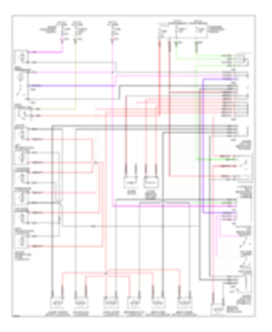
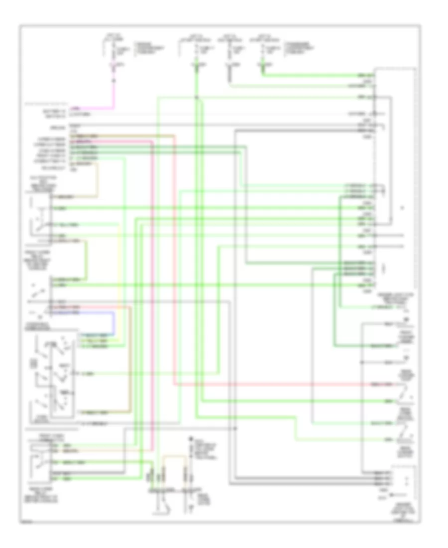
AIR CONDITIONING
Air Conditioning Wiring Diagrams for Land Rover Defender 90 1997
 https://portal-diagnostov.com/license.html
Automotive Electricians Portal FZCO
Automotive Electricians Portal FZCO
https://portal-diagnostov.com/license.html
https://portal-diagnostov.com/license.html
Automotive Electricians Portal FZCO
Automotive Electricians Portal FZCO
List of elements for Air Conditioning Wiring Diagrams for Land Rover Defender 90 1997:
- (behind front of center console) g302
- A/c control unit
- Air conditioning compressor clutch
- Air conditioning compressor clutch relay
- Air conditioning thermostat
- Blower relay
- C154
- C157
- C575
- C581
- C634
- C635
- C636
- Condenser fan
- Condenser fan relay
- Engine compartment fuse box
- Engine control module
- Front blower motor
- Fuse 15 30a
- Fuse 16 15a
- Fuse 17 15a
- Fuse 7 20a
- G101 (right front of engine compartment)
- Header joint
- High
- Hot at all times
- Hot in run or start
- Logic relay
- Low
- Main relay (engine management relay module)
- Medium
- Passenger compartment fuse box
- Red
- Trinary switch
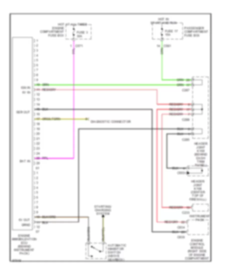
ANTI-THEFT
Anti-theft Wiring Diagram for Land Rover Defender 90 1997
List of elements for Anti-theft Wiring Diagram for Land Rover Defender 90 1997:
- 6v in
- 6v out
- Automatic inhibitor switch (above gearbox)
- Bat in
- C233
- C285
- C287
- C288
- C550
- C634
- C636
- Diagnostic connector
- Engine compartment fuse box
- Engine control module (right side of engine compartment
- Engine immobilization ecu (behind instrument pack)
- Fuse 17 15a
- Fuse 3 30a
- Header joint k108 (center top of firewall)
- Header joint k109 (behind dash trim panel)
- Hot at all times
- Hot in start and run
- Ign in
- Instrument pack
- Passenger compartment fuse box
- Ser out
- Starting/ charging system
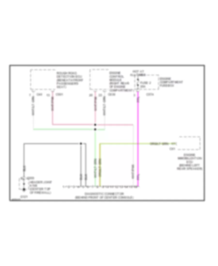
COMPUTER DATA LINES
Computer Data Lines for Land Rover Defender 90 1997
List of elements for Computer Data Lines for Land Rover Defender 90 1997:
- C40
- C501
- C550
- C574
- C61
- C636
- Diagnostic connector (behind front of center console)
- Engine compartment fusebox
- Engine control module (right rear of engine compartment)
- Engine immobilization ecu (behind left rear speaker)
- Fuse 2 20a
- G121
- Header joint k108 (center top of firewall)
- Hot at all times
- Rough road detection ecu (beneath front passenger's seat)
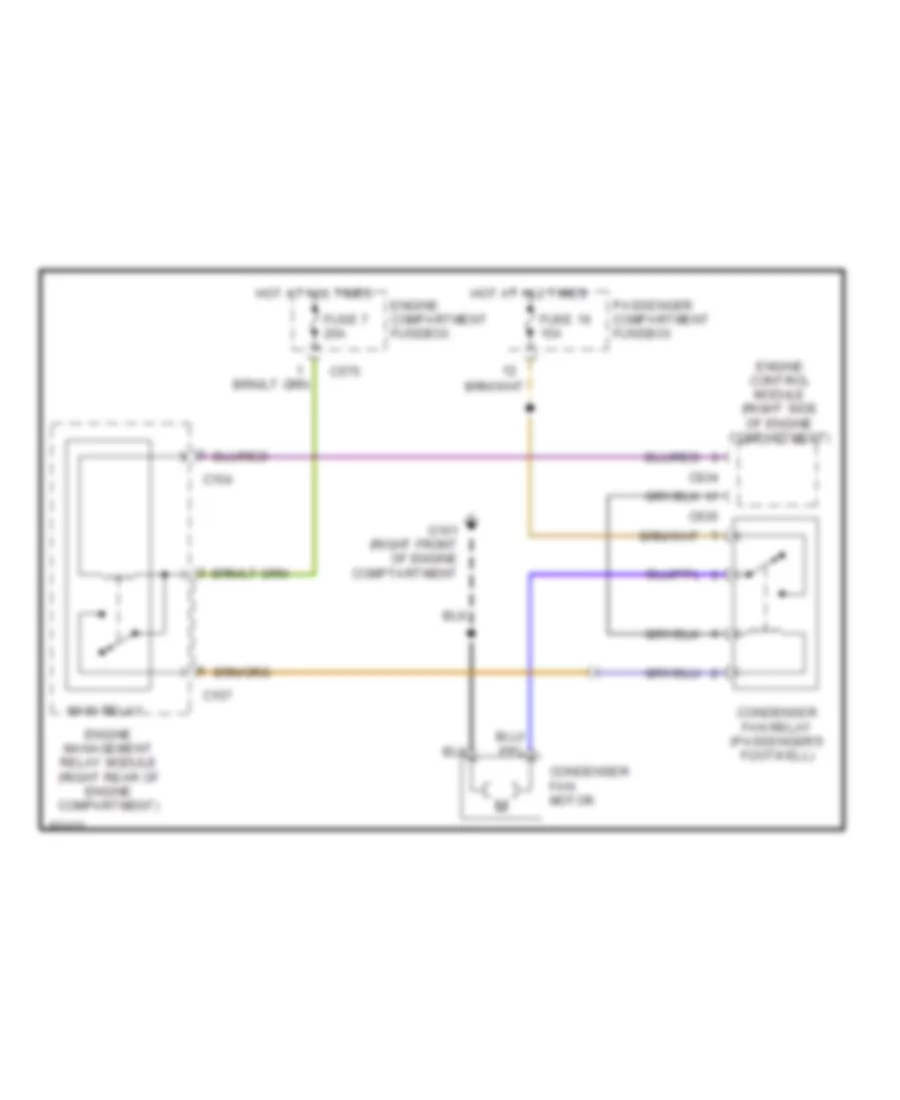
COOLING FAN
Cooling Fan Wiring Diagram for Land Rover Defender 90 1997
List of elements for Cooling Fan Wiring Diagram for Land Rover Defender 90 1997:
- C154
- C157
- C575
- C634
- C635
- Condenser fan motor
- Condenser fan relay (passenger's footwell)
- Engine compartment fusebox
- Engine control module (right side of engine compartment)
- Engine management relay module (right rear of engine compartment)
- Fuse 16 15a
- Fuse 7 20a
- G101 (right front of engine comptartment
- Hot at all times
- Main relay
- Passenger compartment fusebox
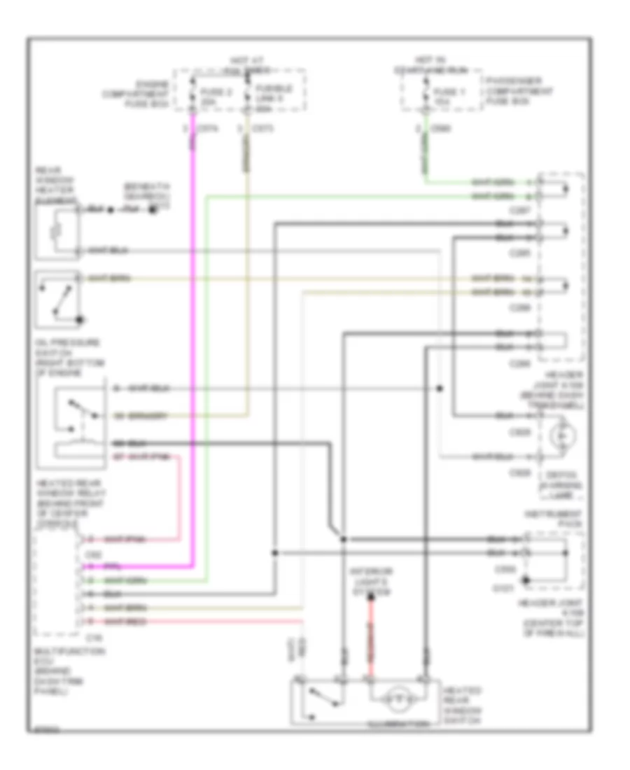
DEFOGGERS
Defogger Wiring Diagram for Land Rover Defender 90 1997
List of elements for Defogger Wiring Diagram for Land Rover Defender 90 1997:
- (beneath gearbox) g113
- C16
- C285
- C286
- C287
- C288
- C550
- C62
- C928
- C929
- Defog warning lamp
- Engine compartment fuse box
- Fuse 1 15a
- Fuse 2 20a
- Fusible link 6 30a
- G121
- Header joint k108 (center top of firewall)
- Header joint k109 (behind dash trim panel)
- Heated rear window relay (behind front of center console
- Heated rear window switch
- Hot at all times
- Hot in start and run
- Illumination
- Instrument pack
- Interior lights system
- Multifunction ecu (behind dash trim panel)
- Oil pressure switch (right bottom of engine
- Passenger compartment fuse box
- Rear window heater element
ENGINE PERFORMANCE
4.0L
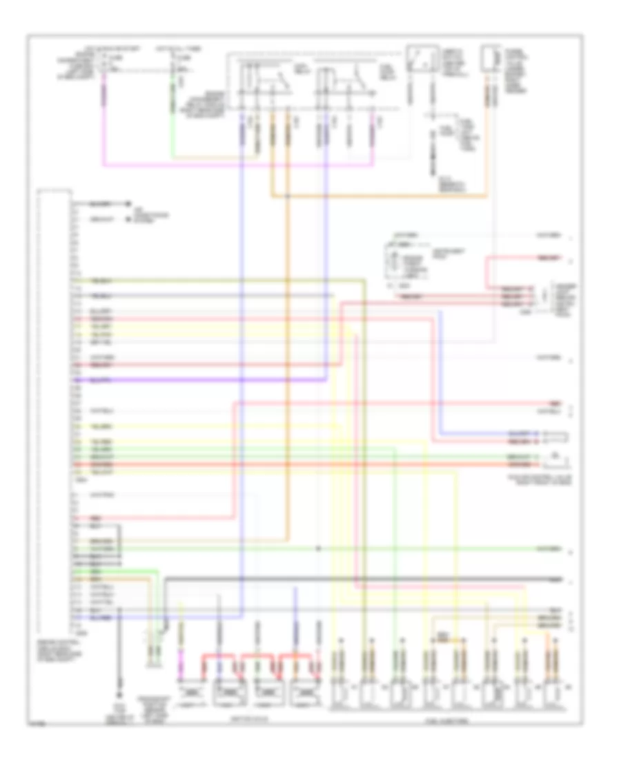
4.0L, Engine Performance Wiring Diagrams (1 of 2) for Land Rover Defender 90 1997
List of elements for 4.0L, Engine Performance Wiring Diagrams (1 of 2) for Land Rover Defender 90 1997:
- 1 & 6
- 2 & 3
- 4 & 7
- 5 & 8
- Air conditioning system
- C154
- C157
- C233
- C288
- C575
- C634
- C635
- Crankshaft position sensor (left side of eng)
- Engine check warning light
- Engine compartment fuse box (left side of eng compt)
- Engine control module (ecm) (right rear side of eng compt)
- Engine management relay module (right rear side of eng compt)
- Fuel injectors
- Fuel pump
- Fuel pump relay
- Fuel tank unit (above fuel tank)
- Fuse 15a
- Fuse 20a
- G113 (beneath gear box)
- G121 (top center of firewall)
- Header joint (behind instru- ment pack)
- Hot at all times
- Hot in run or start
- Idle air control valve (right front of eng)
- Ignition coils
- Inertia switch (center top of firewall)
- Instrument pack
- Main relay
- Nca
- Purge control valve (under bonnet, right inner fender)
- Red
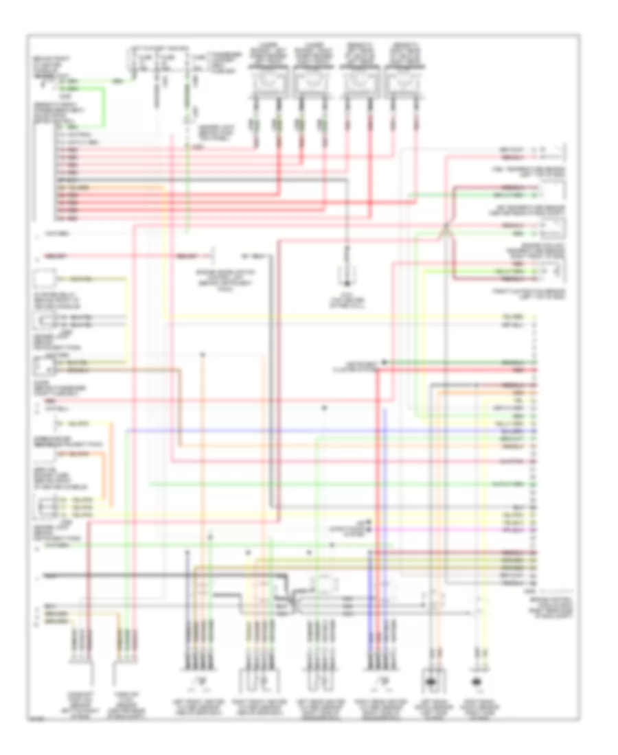
4.0L, Engine Performance Wiring Diagrams (2 of 2) for Land Rover Defender 90 1997
List of elements for 4.0L, Engine Performance Wiring Diagrams (2 of 2) for Land Rover Defender 90 1997:
- (behind front of center console) header joint
- (beneath front passenger's seat) rough road detection ecu
- (beneath left rear of vehicle) left rear speed sensor
- (beneath right rear of vehicle) right rear speed sensor
- (under bonnet, left inner fender) left front speed sensor
- (under bonnet, right inner fender) right front speed sensor
- Air conditioning system
- Air temperature sensor (center rear of eng compt)
- C286
- C287
- C288
- C289
- C580
- C581
- C636
- Camshaft position sensor (bottom right of eng)
- Diode (behind passenger compt fuse box)
- Engine control module (ecm) (right rear side of eng compt)
- Engine coolant temperature sensor (right front of eng)
- Engine immobilization control unit (behind instrument pack)
- Fuel temperature sensor (left top of eng)
- Fuse 15a
- Fuse 20a
- G121 (top center of fire wall)
- Header joint (behind dash trim panel)
- Header joint (behind instrument pack)
- Hot in start and run
- Instrument cluster system
- Left front heated oxygen sensor (above gear box)
- Left rear heated oxygen sensor (right side of transfer box)
- Left-bank knock sensor (left side of eng)
- Mass air flow sensor (center rear of eng compt)
- Nca
- Passenger compart- ment fuse box
- Red
- Right front heated oxygen sensor (above gear box)
- Right rear heated oxygen sensor (right side of transfer box)
- Right-bank knock sensor (right side of eng)
- Service engine timer (behind front of center console)
- Speedometer (behind instrument pack)
- Starter relay (behind front of center console)
- Throttle position sensor (left top of eng)
EXTERIOR LIGHTS
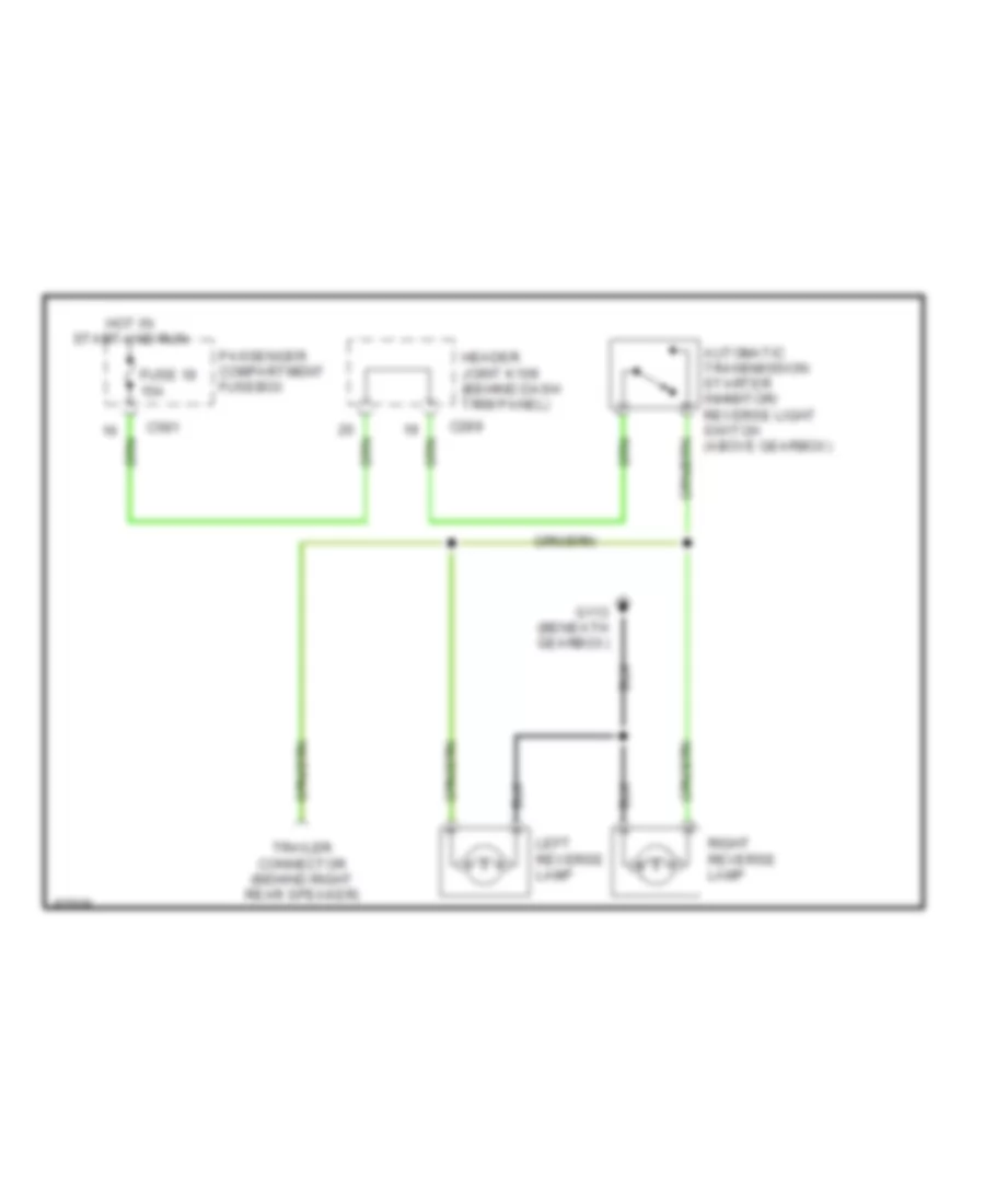
Back-up Lamps Wiring Diagram for Land Rover Defender 90 1997
List of elements for Back-up Lamps Wiring Diagram for Land Rover Defender 90 1997:
- Automatic transmission starter inhibitor/ reverse light switch (above gearbox)
- C289
- C581
- Fuse 18 15a
- G113 (beneath gearbox)
- Header joint k109 (behind dash trim panel)
- Hot in start and run
- Left reverse lamp
- Passenger compartment fusebox
- Right reverse lamp
- Trailer connector (behind right rear speaker)
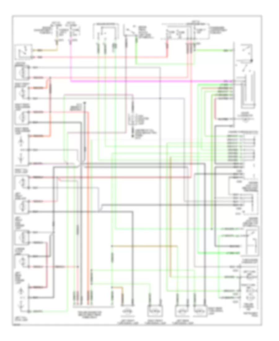
Exterior Lamps Wiring Diagram for Land Rover Defender 90 1997
List of elements for Exterior Lamps Wiring Diagram for Land Rover Defender 90 1997:
- (center of tail door, behind trim panel) g412
- Brake pedal switch (left side of firewall)
- C230
- C233
- C285
- C286
- C550
- Column switch
- Engine compartment fuse box
- Fuse 17 15a
- Fuse 30a
- Fuse 5a
- Fusible link 3 60a
- G113 (beneath gear box)
- G121
- Hazard warning switch
- Header joint k108 (center top of firewall)
- Header joint k109 (behind dash trim panel)
- High mounted stop lamp
- Hot at all times
- Hot in start and run
- Instrument pack
- Left front side marker lamp
- Left front sidelamp
- Left front turn signal lamp
- Left rear side marker lamp
- Left rear turn signal lamp
- Left tail/ stop lamp
- Left turn ind
- License plate lamp
- Lighting switch
- On/off illumination
- Passenger compartment fuse box
- Red
- Right front side marker lamp
- Right front sidelamp
- Right front turn signal lamp
- Right rear side marker lamp
- Right rear turn signal lamp
- Right tail/ stop lamp
- Right turn ind
- Trailer connector (below right rear wheelarch)
- Trailer warning ind
- Turn/hazard warning unit
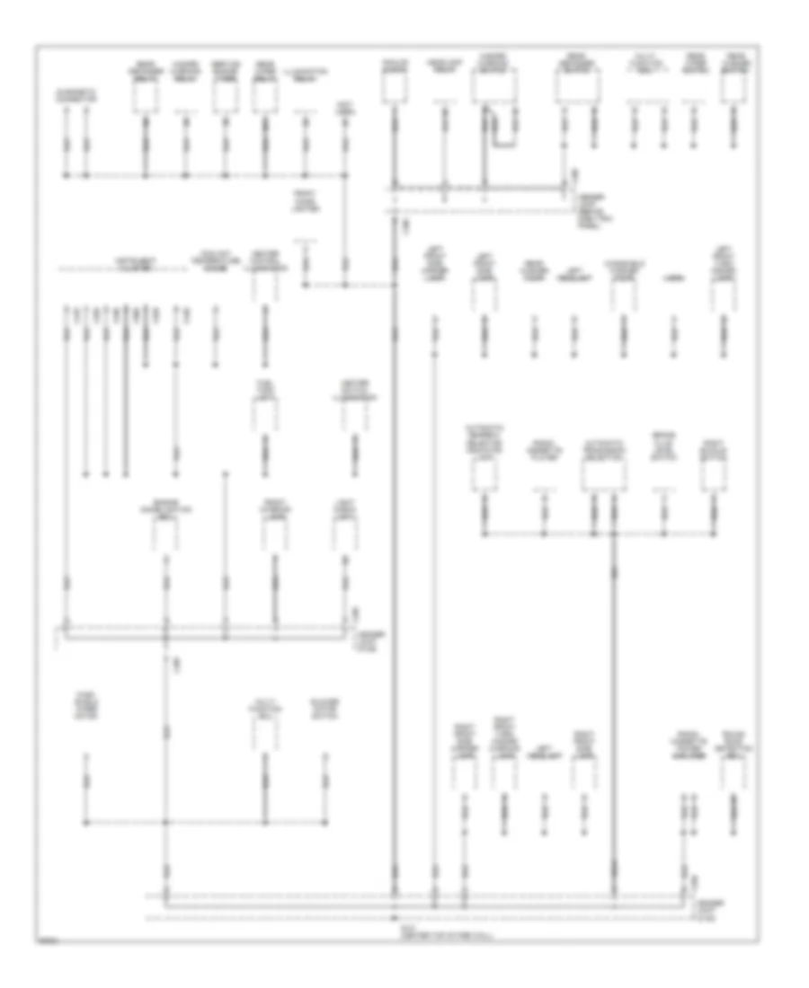
GROUND DISTRIBUTION
Ground Distribution Wiring Diagram (1 of 2) for Land Rover Defender 90 1997
List of elements for Ground Distribution Wiring Diagram (1 of 2) for Land Rover Defender 90 1997:
- (not used)
- 87a
- Analog clock
- Automatic gearbox selector indicator lamp
- Automatic tranmission selection
- Blower motor switch
- Brake fluid level switch
- C233
- C285
- C286
- C550
- C860
- C928
- C936
- C939
- C940
- Coolant temperature gauge
- Diagnostic connector
- Engine immobilisation ecu
- Front cigar lighter
- Front interior lamp
- Fuel tank unit
- G121 (center top of fire wall)
- Hazard warning relay
- Hazard warning switch
- Header joint (behind dash trim panel)
- Header joint (k108)
- Header joint (k109)
- Headlamp relay
- Heater control illumination
- Heater switch illumination
- Horn
- Illumination relay
- Instrument cluster
- Left front side lamp
- Left front side marker lamp
- Left front turn/ hazard lamp
- Left headlamp
- Light check unit
- Multi- function ecu
- Radio/ cassette player
- Radio/ cassette power amplifier
- Rear defogger relay
- Rear defogger switch
- Rear washer pump
- Rear washer switch
- Rear wiper relay
- Rear wiper switch
- Right buckle switch
- Right front side lamp
- Right front side marker lamp
- Right front turn/ hazard warning lamp
- Rough road detection ecu
- Service engine timer
- Wind- shield wiper motor
- Windshield washer pump
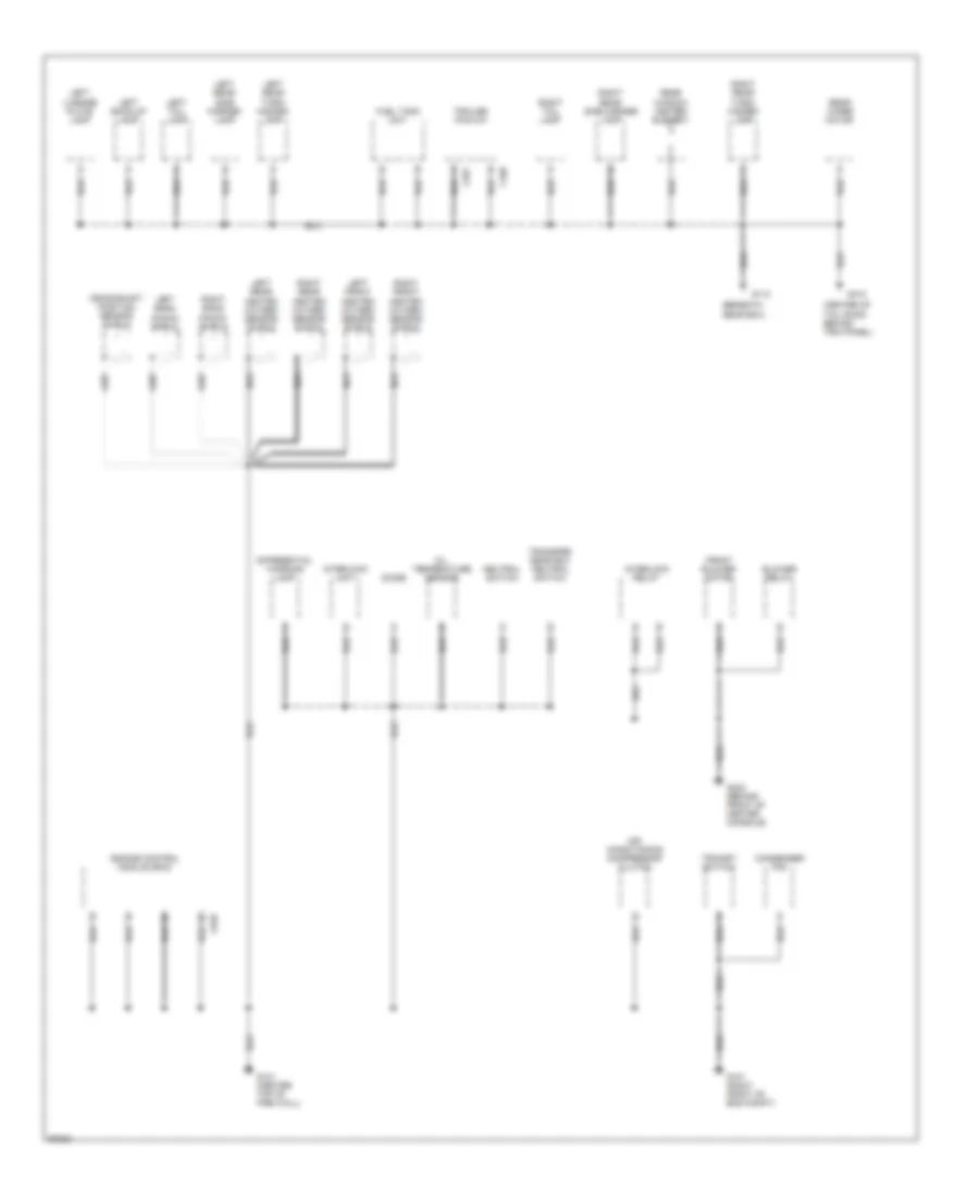
Ground Distribution Wiring Diagram (2 of 2) for Land Rover Defender 90 1997
List of elements for Ground Distribution Wiring Diagram (2 of 2) for Land Rover Defender 90 1997:
- (beneath gear box)
- (center of tail door, behind trim panel)
- Air conditioning compressor clutch
- Blower relay
- C499
- C557
- C635
- Condenser fan
- Crankshaft position sensor shield
- Differential warning lamp
- Diode
- Engine control module (ecm)
- Front blower motor
- Fuel tank unit
- G101 (right front of eng compt)
- G113
- G121 (center top of fire wall)
- G302 (behind front of center console)
- G412
- Interlock relay
- Interlock unit
- Left back-up lamp
- Left bank knock shield
- Left front heated oxygen sensor shield
- Left license plate lamp
- Left rear heated oxygen sensor shield
- Left rear side marker lamp
- Left rear turn/ hazard lamp
- Left tail lamp
- Nca
- Neutral switch
- Oil temperature sensor
- Rear window heater element
- Rear wiper motor
- Right bank knock shield
- Right front heated oxygen sensor shield
- Right rear heated oxygen sensor shield
- Right rear side marker lamp
- Right rear turn/ hazard lamp
- Right tail lamp
- Trailer pick-up
- Transfer gear box neutral switch
- Trinary switch
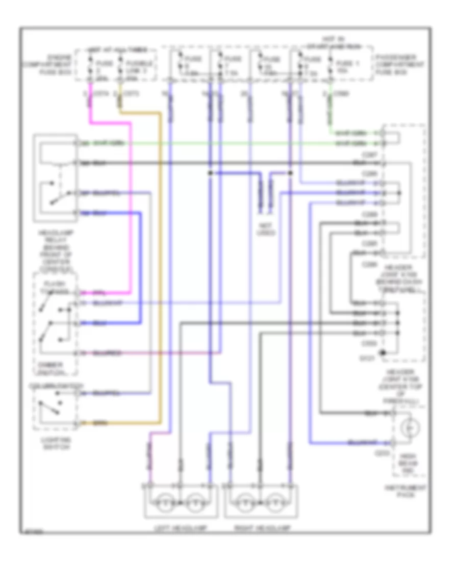
HEADLIGHTS
Headlight Wiring Diagram for Land Rover Defender 90 1997
List of elements for Headlight Wiring Diagram for Land Rover Defender 90 1997:
- C233
- C285
- C286
- C287
- C289
- C550
- Column switch
- Dimmer switch
- Engine compartment fuse box
- Flash to pass
- Fuse 1 15a
- Fuse 20a
- Fuse 7.5a
- Fusible link 3 60a
- G121
- Header joint k108 (center top of firewall)
- Header joint k109 (behind dash trim panel)
- Headlamp relay (behind front of center console)
- High beam ind
- Hot at all times
- Hot in start and run
- Instrument pack
- Left headlamp
- Lighting switch
- Not used
- Passenger compartment fuse box
- Right headlamp
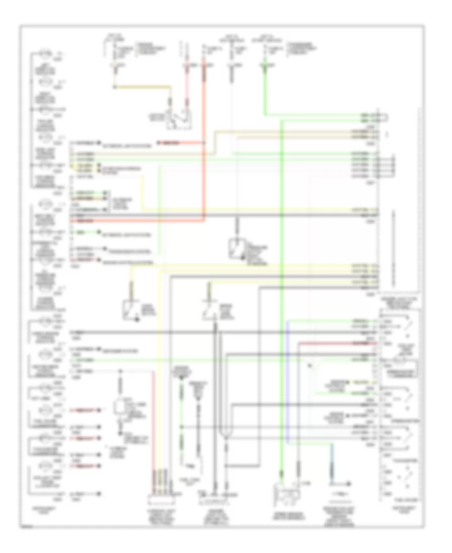
INSTRUMENT CLUSTER
Instrument Cluster Wiring Diagram for Land Rover Defender 90 1997
List of elements for Instrument Cluster Wiring Diagram for Land Rover Defender 90 1997:
- (beneath gear box) g113
- Brake fluid level switch
- C195
- C218
- C219
- C230
- C233
- C269
- C285
- C287
- C288
- C289
- C550
- C580 red
- C842
- C860
- C928
- C929
- C932
- C935
- C936
- C937
- C938
- C939
- C940
- C943
- Charge warning indicator
- Check engine warning indicator
- Coolant temp gauge
- Coolant temp gauge illumination
- Defogger system
- Differential lock warning indicator
- Engine compartment fuse box
- Engine controls system
- Engine coolant temperature sensor (front right side of engine)
- Exterior lights system
- Fuel gauge
- Fuel gauge illumination
- Fuel tank unit
- Fuse 1 15a
- Fuse 12 5a
- Fuse 18 15a
- Fusible link 4 30a
- G121
- G121 (center top of firewall)
- Hand- brake switch
- Header joint k108 (center top of firewall)
- Header joint k109 (behind dash trim panel)
- Heated rear window indicator
- High beam warning indicator
- Hot at all times
- Hot in acc and run
- Hot in start and run
- Instrument pack
- Interior lights system
- Left direction indicator
- Lighting switch
- Not used
- Not used v101 (above gearbox)
- Oil pressure switch (right bottom of engine)
- Oil pressure warning indicator
- Passenger compartment fuse box
- Red
- Right direction indicator
- Seat belt warning indicator
- Side lamp warning indicator
- Speed sensor (above gearbox)
- Speedometer
- Speedometer illumination
- Starting/charging system
- Tachometer
- Tachometer illumination
- Trailer warning indicator
- Transmission system
- Warning light check unit (behind dash trim panel)
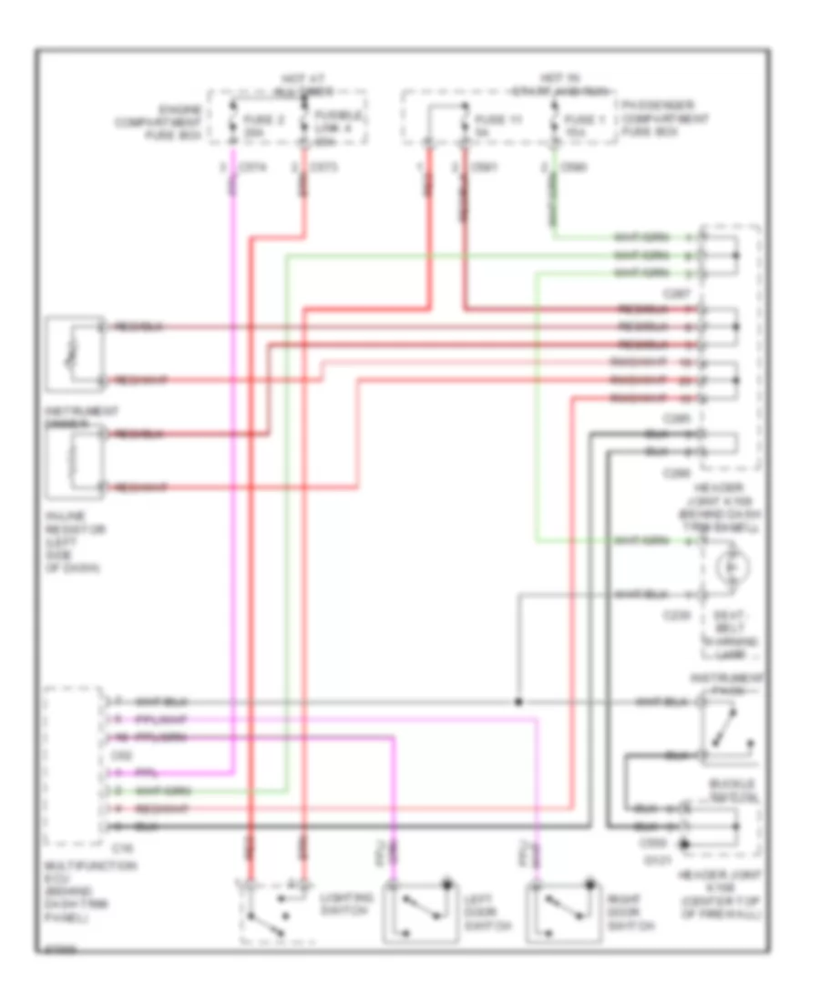
INTERIOR LIGHTS
Interior Light Wiring Diagram for Land Rover Defender 90 1997
List of elements for Interior Light Wiring Diagram for Land Rover Defender 90 1997:
- 87a
- Analog clock illumination
- C16
- C285
- C286
- C287
- C288
- C356
- C357
- C550
- C573
- C574
- C62
- Cigar lighter illumination
- Coolant temperature gauge illumination
- Defogger switch illumination
- Dimmer switch
- Engine compartment fuse box
- Front interior lamp
- Fuel gauge illumination
- Fuse 1 15a
- Fuse 17 15a
- Fuse 20a
- Fuse 30a
- Fuse 5a
- Fusible link 4 30a
- G121
- Gear box selector switch lamp
- Hazard warning switch illumination
- Header joint k108 (center top of firewall)
- Header joint k109 (behind dash trim panel)
- Hot at all times
- Hot in start and run
- Illumination relay (behind front of center console)
- In-line resistor (left side of dash)
- Left door switch
- Left heater control illumination
- Lighting switch
- Multifuction ecu (behind dash trim panel)
- Passenger compartment fuse box
- Rear interior lamp
- Rear washer switch illumination
- Rear wiper switch illumination
- Red
- Red/pnk
- Right door switch
- Right heater control illumination
- Speedometer illumination
- Tachometer illumination
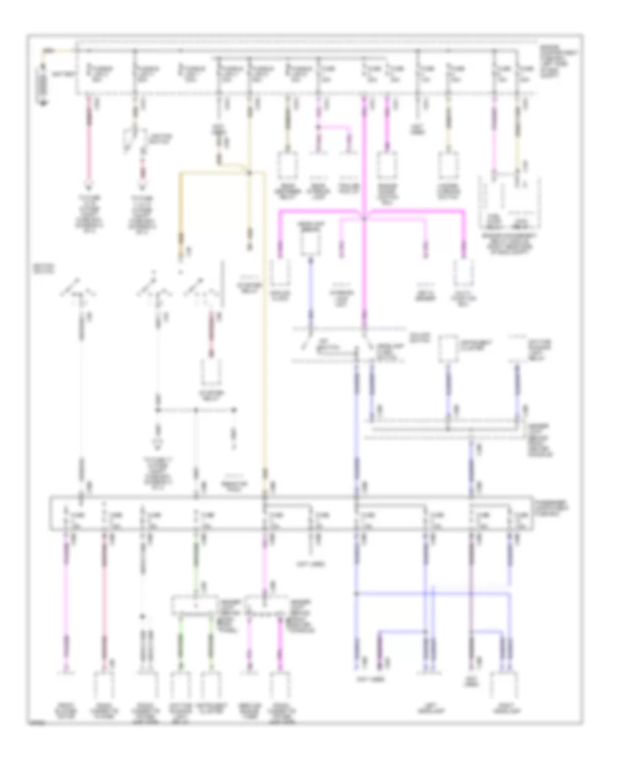
POWER DISTRIBUTION
Power Distribution Wiring Diagram (1 of 3) for Land Rover Defender 90 1997
List of elements for Power Distribution Wiring Diagram (1 of 3) for Land Rover Defender 90 1997:
- (not used)
- 87a
- Analog clock
- Battery
- C157
- C28
- C287
- C289
- C408
- C409
- C570
- C571
- C573
- C574
- C575
- C580
- C90
- C94
- C957
- C98
- C99
- Center console)
- Column switch
- Daytime running light relay
- Dip switch
- Engine compartment fuse box (left side of eng compt)
- Engine immobi- lization ecu
- Engine management relay module (right rear side of eng compt)
- Front blower motor
- Fuel pump relay
- Fuse 10a
- Fuse 15a
- Fuse 20a
- Fuse 30a
- Fuse 5a
- Fuse 7.5a
- Fusible link 1 100a
- Fusible link 2 60a
- Fusible link 3 60a
- Fusible link 4 30a
- Fusible link 5 60a
- Fusible link 6 30a
- Hazard warning switch
- Header joint (behind dash c287 trim panel)
- Header joint (behind front c289
- Header joint (behind front center console)
- Headlamp flash switch
- Headlamp relay
- Ignition switch
- Iii
- Instrument cluster
- Interior lamp unit
- Key in sensor
- Left headlamp
- Lighting switch
- Main relay
- Multi- function ecu
- Passenger compatment fuse box
- Radio cassette player
- Radio/ cassette power amplifier
- Rear defogger relay
- Rear interior lamp
- Red
- Resistor pack
- Right headlamp
- Service engine timer
- Starter relay
- To fuse 11 & 12 in pass compt fuse box (diagram 2 of 3)
- To fuse 13-16 in pass compt fuse box (diagram 2 of 3)
- To fuse 17 in pass compt fuse box (diagram 3 of 3)
- Trailer pick up
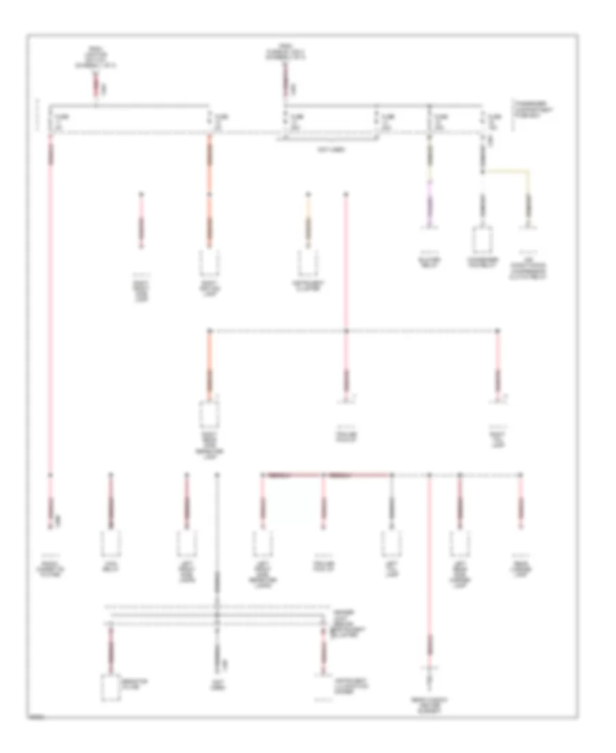
Power Distribution Wiring Diagram (2 of 3) for Land Rover Defender 90 1997
List of elements for Power Distribution Wiring Diagram (2 of 3) for Land Rover Defender 90 1997:
- (not used)
- Air conditioning compressor clutch relay
- Blower relay
- C098
- C285
- C407
- C581
- Condenser fan relay
- From fusible link 2 (diagram 1 of 3)
- From lighting switch (diagram 1 of 3)
- Fuse 15a
- Fuse 20a
- Fuse 30a
- Fuse 5a
- Header joint (behind instrument cluster)
- Instrument cluster
- Instrument illumination dimmer
- Left front side lamps
- Left front side repeater lamps
- Left rear side marker lamp
- Left tail lamp
- Main relay
- Passenger compartment fuse box
- Radio/ cassette player
- Rear license lamp
- Rear window heater element
- Red
- Resistor in-line
- Right driving lamp
- Right front side lamp
- Right rear side repeater lamp
- Right tail lamp
- Trailer pick up
- Trailer pick-up
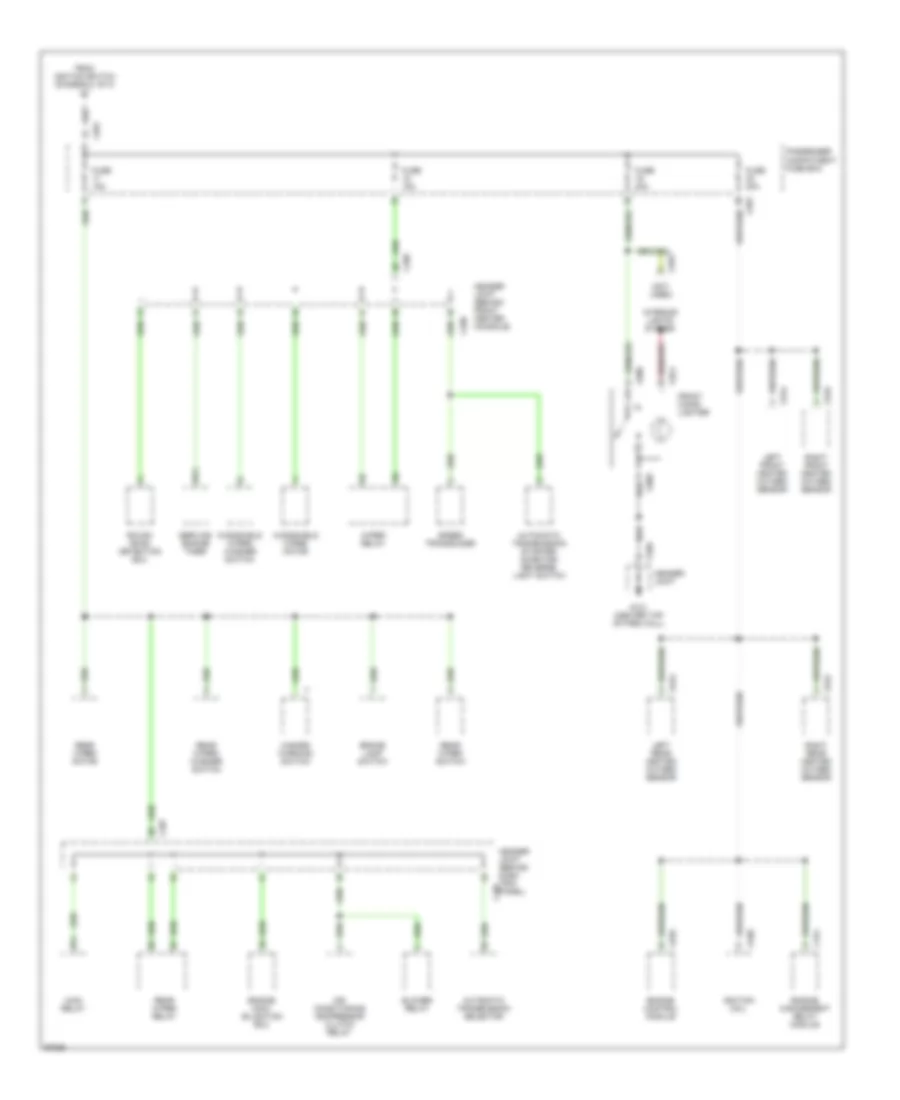
Power Distribution Wiring Diagram (3 of 3) for Land Rover Defender 90 1997
List of elements for Power Distribution Wiring Diagram (3 of 3) for Land Rover Defender 90 1997:
- (not used)
- 87a
- Air conditioning compressor clutch relay
- Automatic transmission selector
- Automatic transmission starter inhibitor/ reverse light switch
- Blower relay
- Brake lamp switch
- C074
- C086
- C089
- C154
- C287
- C289
- C550
- C581
- C630
- C635
- C642
- C643
- C644
- C645
- C953
- Engine control module
- Engine immo- bilisation ecu
- Engine management relay module
- From ignition switch (diagram 1 of 3)
- Front cigar lighter
- Fuse 15a
- Fuse 20a
- G121 (center top of fire wall)
- Hazard warning switch
- Header joint
- Header joint (behind dash trim panel)
- Header joint (behind front center console)
- Ignition coil
- Interior lights system
- Left front heated oxygen sensor
- Left rear heated oxygen sensor
- Main relay
- Passenger compatment fuse box
- Rear wiper motor
- Rear wiper relay
- Rear wiper switch
- Rear wiper/ washer switch
- Right front heated oxygen sensor
- Right rear heated oxygen sensor
- Rough road detection ecu
- Service engine timer
- Speed transducer
- Windshield wiper motor
- Windshield wiper/ washer switch
- Wiper relay
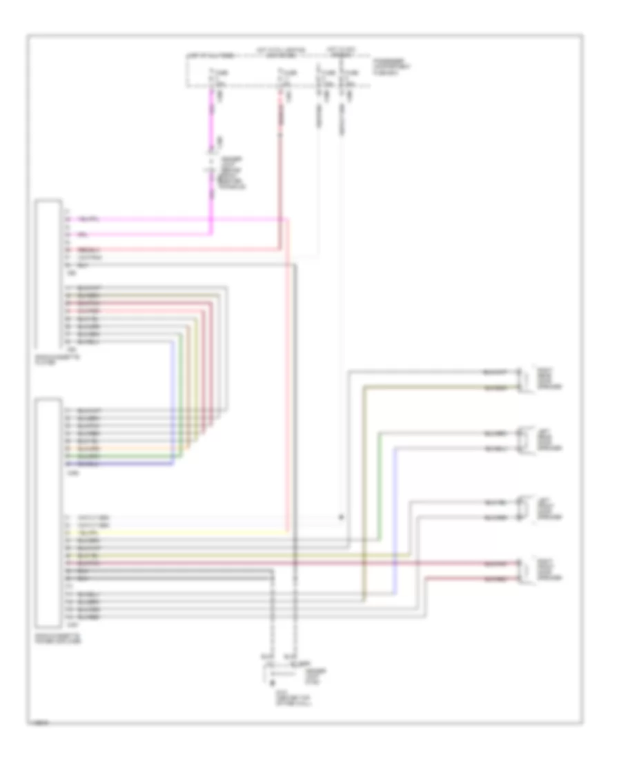
RADIO
Radio Wiring Diagrams for Land Rover Defender 90 1997
List of elements for Radio Wiring Diagrams for Land Rover Defender 90 1997:
- C289
- C491
- C492
- C550
- C580
- C581
- C92
- C98
- Fuse 10a
- Fuse 15a
- Fuse 5a
- Fuse 7.5a
- G121 (center top of fire wall)
- Header joint (behind front c289 center console)
- Header joint (k108)
- Hot at all times
- Hot in acc or run
- Hot with lighting switch on
- Left front door speaker
- Left rear door speaker
- Passenger compartment fuse box
- Radio/cassette player
- Radio/cassette power amplifier
- Right front door speaker
- Right rear door speaker
SHIFT INTERLOCKS
Shift Interlock Wiring Diagram for Land Rover Defender 90 1997
List of elements for Shift Interlock Wiring Diagram for Land Rover Defender 90 1997:
- Automatic transmission selector (behind center console)
- Automatic transmission starter inhibitor/ reverse light switch (above gearbox)
- Brake pedal switch (left side of firewall)
- C285
- C286
- C287
- C289
- C550
- C57
- C62
- Diode (behind dash trim panel)
- Diode (behind passenger compartment fuse box)
- Engine compartment fuse box
- Engine immobilization ecu (behind instrument pack)
- Fuse 18 15a
- Fuse 20a
- G121
- G121 (center top of firewall)
- Header joint k108 (center top of firewall)
- Header joint k109 (behind dash trim panel)
- Hot at all times
- Hot in start and run
- Interlock relay (behind front of center console)
- Interlock shift solenoid
- Key in sensor (behind instrument pack)
- Key interlock solenoid (behind instrument pack)
- Multifuction ecu (behind dash trim panel)
- Park1
- Park2
- Passenger compartment fuse box
- Transfer gearbox interlock unit (above gearbox)
- Transfer gearbox neutral switch (above gearabox)
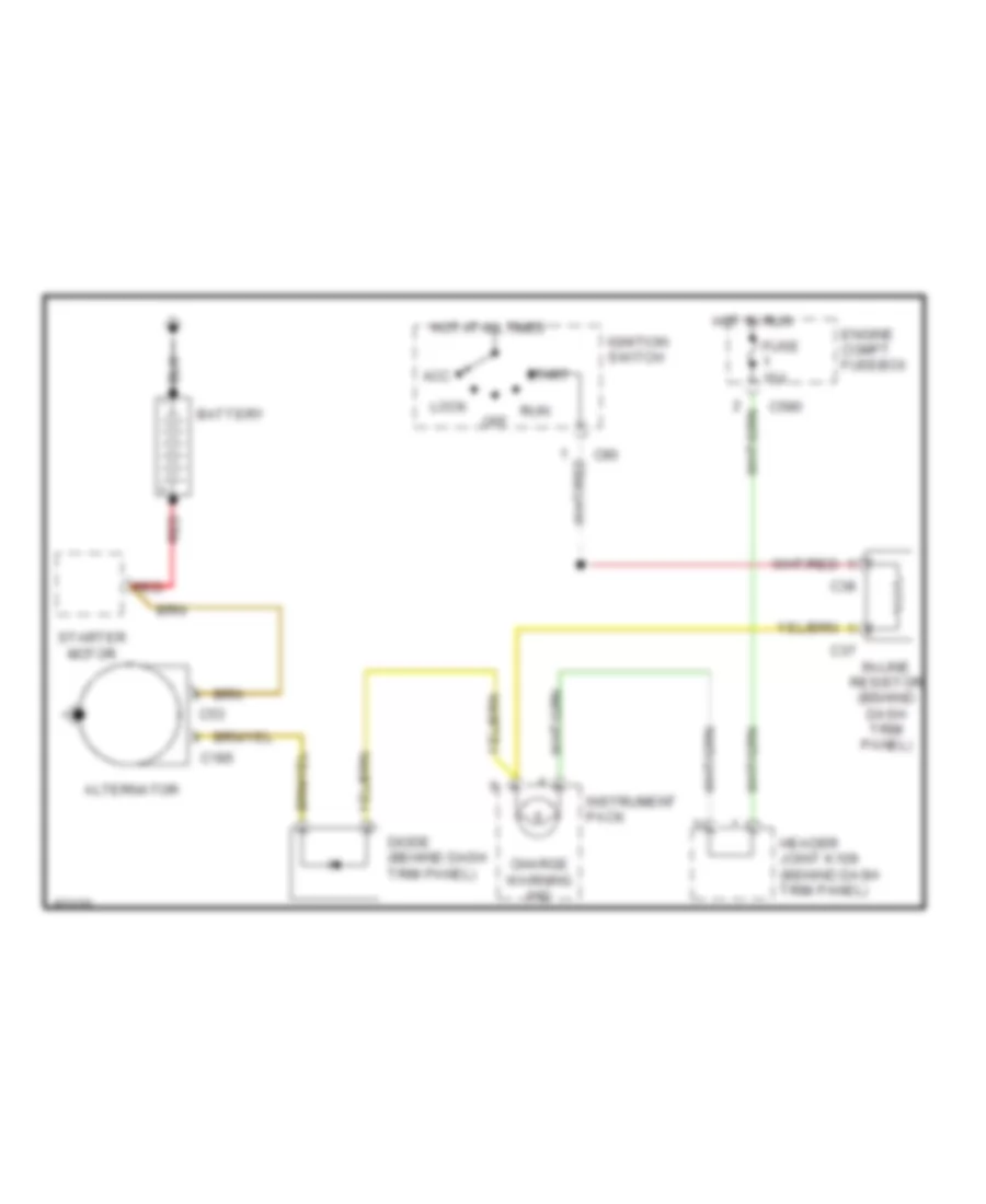
STARTING/CHARGING
Charging Wiring Diagram for Land Rover Defender 90 1997
List of elements for Charging Wiring Diagram for Land Rover Defender 90 1997:
- Acc
- Alternator
- Battery
- C185
- C37
- C38
- C53
- C580
- C90
- Charge warning ind
- Diode (behind dash trim panel)
- Engine compt fusebox
- Fuse 15a
- Header joint k109 (behind dash trim panel)
- Hot at all times
- Hot in run
- Ignition switch
- In-line resistor (behind dash trim panel)
- Instrument pack
- Lock
- Off
- Red
- Run
- Start
- Starter motor
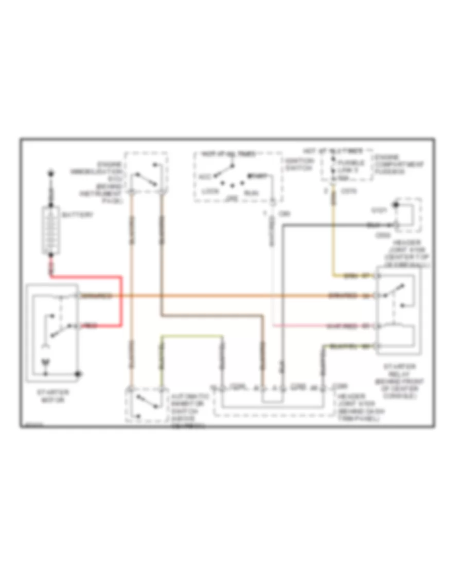
Starting Wiring Diagram for Land Rover Defender 90 1997
List of elements for Starting Wiring Diagram for Land Rover Defender 90 1997:
- Acc
- Automatic inhibitor switch (above gearbox)
- Battery
- C285
- C286
- C550
- C570
- C90
- Engine compartment fusebox
- Engine immobilisation ecu (behind instrument pack)
- Fusible link 5 60a
- G121
- Header joint k108 (center top of firewall)
- Header joint k109 (behind dash trim panel)
- Hot at all times
- Ignition switch
- Lock
- Off
- Red
- Run
- Start
- Starter motor
- Starter relay (behind front of center console)
WARNING SYSTEMS
Warning System Wiring Diagrams for Land Rover Defender 90 1997
List of elements for Warning System Wiring Diagrams for Land Rover Defender 90 1997:
- Buckle switch
- C16
- C230
- C285
- C286
- C287
- C550
- C62
- Engine compartment fuse box
- Fuse 1 15a
- Fuse 11 5a
- Fuse 2 20a
- Fusible link 4 30a
- G121
- Header joint k108 (center top of firewall)
- Header joint k109 (behind dash trim panel)
- Hot at all times
- Hot in start and run
- In-line resistor (left side of dash)
- Instrument dimmer
- Instrument pack
- Left door switch
- Lighting switch
- Multifunction ecu (behind dash trim panel)
- Passenger compartment fuse box
- Red
- Right door switch
- Seat- belt warning lamp
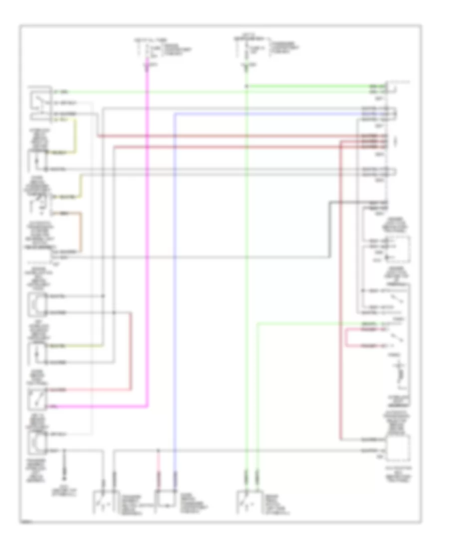
WIPER/WASHER
Wiper/Washer Wiring Diagram for Land Rover Defender 90 1997
List of elements for Wiper/Washer Wiring Diagram for Land Rover Defender 90 1997:
- 87a
- Battery in
- C16
- C286
- C287
- C288
- C289
- C388
- C550
- C62
- C835
- Engine compartment fuse box
- Fast
- Flick wipe
- Fr wipe out
- Front wash in
- Front wash/ wipe switch
- Front washer pump
- Front wiper relay (behind front of center console)
- Fuse 1 15a
- Fuse 17 15a
- Fuse 18 15a
- Fuse 2 20a
- G121
- G412 (center of tail door, behind trim panel)
- Ground
- Header joint k108 (center top of firewall)
- Header joint k109 (behind dash trim panel)
- Hot at all times
- Hot in acc and run
- Hot in start and run
- Ignition in
- Inter
- Intermittent in
- Multifuction ecu (behind dash trim panel)
- Passenger compartment fuse box
- Rear washer pump
- Rear washer switch
- Rear wiper motor
- Rear wiper relay (behind front of center console)
- Rear wiper switch
- Slow
- Wash in rear
- Wash switch
- Windshield wiper motor
- Wiper in rear
- Wiper out rear

 Čeština
 Dansk
Dansk Deutsch
 English
 English
 Español
 Suomi
Suomi Français
 Français
 עברית
עברית Hrvatski
 Magyar
 Italiano
 日本語
日本語 한국어
한국어 Nederlands
 Polski
 Português
 Português
 Română
 Русский
 Slovenčina
 Slovenščina
 Svenska
 Türkçe
 中文 (中国)