AIR CONDITIONING
2.0L
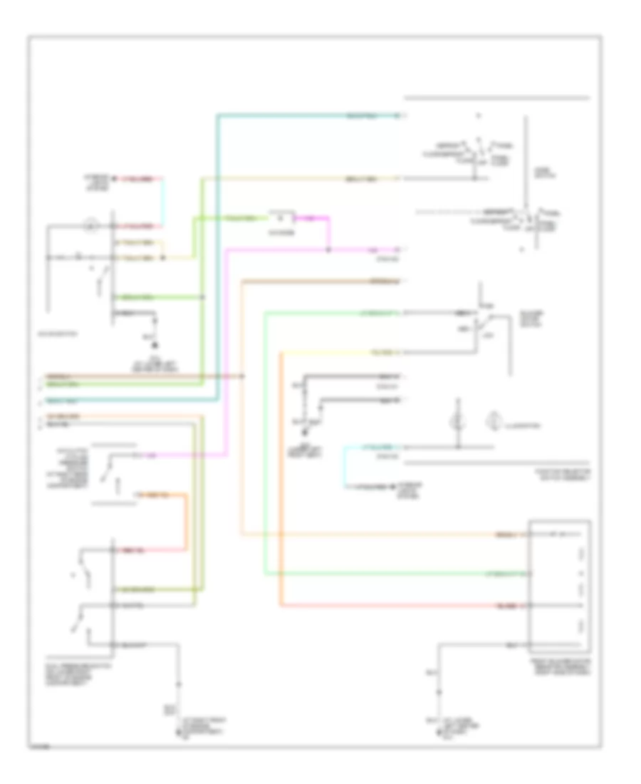
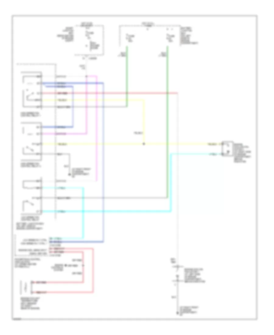
2.0L, Manual A/C Wiring Diagram (1 of 2) for Mazda Tribute s 2005
 https://portal-diagnostov.com/license.html
Automotive Electricians Portal FZCO
Automotive Electricians Portal FZCO
https://portal-diagnostov.com/license.html
https://portal-diagnostov.com/license.html
Automotive Electricians Portal FZCO
Automotive Electricians Portal FZCO
List of elements for 2.0L, Manual A/C Wiring Diagram (1 of 2) for Mazda Tribute s 2005:
- (at lower left center of dash) g14
- (at right front of engine compartment) g2
- (at right front of engine compartment) g5
- (at right front of engine compt) g5
- (behind left rear wheelwell) g20
- 0140-175b
- A/c clutch relay
- A/c clutch solenoid (at left front of engine)
- A/c compressor clutch diode
- Battery junction box (on left side of engine compartment)
- Blower motor relay (behind lower left center of dash)
- Cooling fan relay
- Engine controls system
- Engine cooling fan motor 1 (front of engine compt)
- Engine cooling fan motor 2 (front of engine compt)
- Front blower motor
- Fuse 15a
- Fuse 26 5a
- Fuse 30a
- Fuse 40a
- Fuse 5 2a
- High speed fan control relay 1
- Hot at all times
- Hot in on or start
- J-2280a
- J-2280b
- Low speed fan control relay
- Pcm power diode
- Pcm power relay
- Powertrain control module (pcm) (at upper center of firewall)
- Red
- Smart junction box (rear center of engine compt)
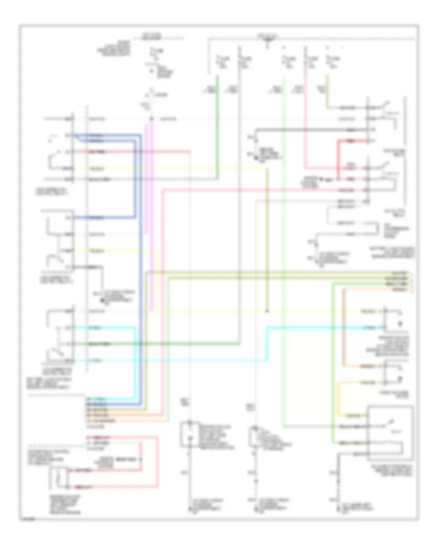
2.0L, Manual A/C Wiring Diagram (2 of 2) for Mazda Tribute s 2005
List of elements for 2.0L, Manual A/C Wiring Diagram (2 of 2) for Mazda Tribute s 2005:
- (at lower left center of dash) g14
- (at right front of engine compartment) g3
- 0740-101
- 0740-102
- 0740-103
- A/c clutch cycling pressure switch (at right rear of engine compartment)
- A/c diode
- A/c on switch
- Blower motor switch
- Defrost
- Dual pressure switch (on lower right front of engine compartment)
- Floor
- Floor/defrost
- Front blower motor resistor assembly (right side of dash)
- Function selector switch assembly
- G14 (at lower left center of dash)
- G15 (under left front seat)
- High
- Illumination
- Interior lights system
- Low
- Med 1
- Med 2
- Mode switch
- Off
- Panel
- Panel/ floor
3.0L
3.0L, Manual A/C Wiring Diagram (1 of 2) for Mazda Tribute s 2005
List of elements for 3.0L, Manual A/C Wiring Diagram (1 of 2) for Mazda Tribute s 2005:
- (at lower left center of dash) g14
- (at right front of engine compartment) g2
- (at right front of engine compartment) g5
- (behind left rear wheelwell) g20
- 0140-275b
- 0140-275e
- 87a
- A/c clutch relay
- A/c clutch solenoid (at left front of engine)
- A/c compressor clutch diode
- Battery junction box (on left side of engine compartment)
- Battery junction box (on left side of engine compartment)
- Blower motor relay (behind lower left center of dash)
- Engine control system
- Engine controls system
- Engine coolant temperature (ect) sensor (at right rear of engine)
- Engine cooling fan motor 1 (at left side of engine compartment, behind radiator)
- Engine cooling fan motor 2 (at right side of engine compartment, behind radiator)
- Front blower motor
- Fuse 15a
- Fuse 2a
- Fuse 30a
- Fuse 40a
- Fuse 50a
- High speed fan control relay 1
- High speed fan control relay 2
- Hot at all times
- Hot in on or start
- J-2280b
- Low speed fan control relay
- Pcm power diode
- Pcm power relay
- Powertrain control module (pcm) (at upper center of firewall)
- Red
- Smart junction box (rear center of) engine compt)
3.0L, Manual A/C Wiring Diagram (2 of 2) for Mazda Tribute s 2005
List of elements for 3.0L, Manual A/C Wiring Diagram (2 of 2) for Mazda Tribute s 2005:
- (at lower left center of dash) g14
- (at right front of engine compartment) g3
- (under left front seat) g15
- 0740-101
- 0740-102
- 0740-103
- A/c clutch cycling pressure switch (at right rear of engine compartment)
- A/c diode
- A/c on switch
- Blower motor switch
- Defrost
- Dual pressure switch (on lower right front of engine compartment)
- Floor
- Floor/defrost
- Front blower motor resistor assembly (right side of dash)
- Function selector switch assembly
- Fuse 5a
- G14 (at lower left center of dash)
- High
- Hot in on or start
- Illumination
- Interior lights system
- J-2280a
- Low
- Med 1
- Med 2
- Mode switch
- Off
- Panel
- Panel/ floor
- Smart junction box (rear center of engine compt)
ANTI-LOCK BRAKES
Anti-lock Brakes Wiring Diagram for Mazda Tribute s 2005
List of elements for Anti-lock Brakes Wiring Diagram for Mazda Tribute s 2005:
- Abs control module (at left rear of engine compartment)
- Abs test connector (at left rear of engine compt)
- Battery junction box (on left side of engine compartment)
- Brake fluid level switch (on brake master cylinder fluid reservoir)
- Brake pedal position switch (on bracket, above brake pedal)
- Computer data lines
- Computer data lines system
- Cruise control system
- Fuse 15a
- Fuse 30a
- Fuse 5a
- Fuse 60a
- G4 (at left front of engine compartment)
- Hot at all times
- Hot in run or start
- J-2280b
- J-2280c
- Left front wheel speed sensor (on left rear of engine compt)
- Left rear wheel speed sensor (at left rear wheelwell)
- Nca
- Red
- Red/pnk
- Right front wheel speed sensor (on right rear of engine compt)
- Right rear wheel speed sensor (at right rear wheelwell)
- Smart junction box (rear center of engine compartment)
- System
ANTI-THEFT
Forced Entry Wiring Diagram for Mazda Tribute s 2005
List of elements for Forced Entry Wiring Diagram for Mazda Tribute s 2005:
- (at rear of left rear door)
- (not used)
- Ajar
- All unlock & lock relay
- Anti-theft hood switch
- Battery junction box (on left side of engine compartment)
- C-312
- Driver side front door lock unit (rear of left front door)
- Driver unlock relay
- Fuse 10a
- Fuse 25a
- Fuse 30a
- Fuse 40a
- G16 (behind left rear wheelwell)
- G17 (under left front seat)
- G20 (behind left rear wheelwell)
- G3 (at right front of engine compartment)
- Hot at all times
- Ignition switch
- J-2280a
- J-2280b
- J-2280c
- J-2280d
- J-2280e
- Left rear door lock actuator
- Liftgate ajar switch
- Liftgate glass ajar switch
- Liftgate lock actuator
- Lock
- Master window/ door lock/ unlock switch
- Microcomputer
- Passenger side front door lock unit (rear of front passenger's door)
- Red
- Right rear door lock actuator (at rear of right rear door)
- Smart junction box (rear center of engine compt)
- Unlock
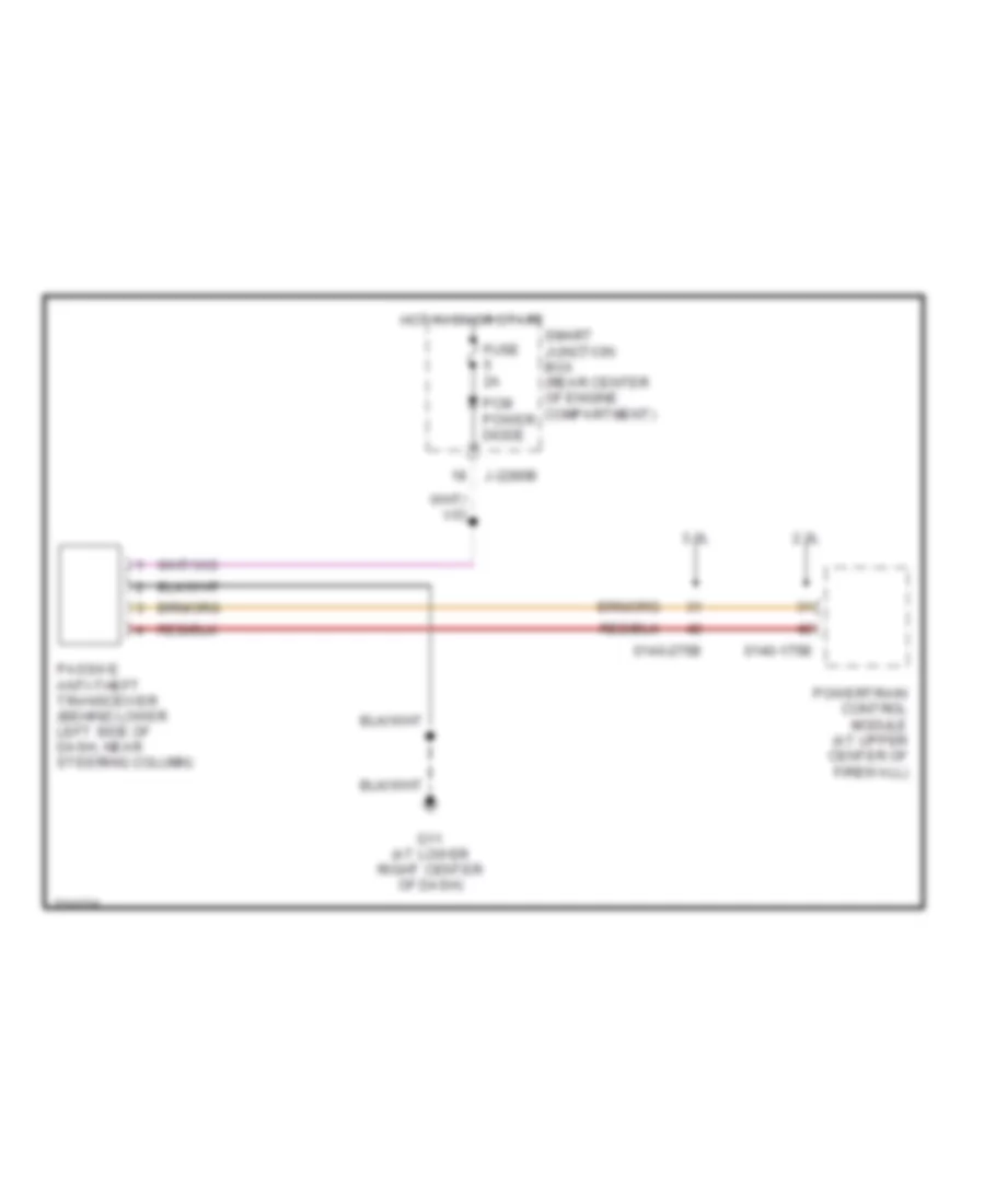
Passive Anti-theft Wiring Diagram for Mazda Tribute s 2005
List of elements for Passive Anti-theft Wiring Diagram for Mazda Tribute s 2005:
- 0140-175b
- 0140-275b
- 2.3l
- 3.0l
- Fuse 2a
- G11 (at lower right center of dash)
- Hot in on or start
- J-2280b
- Passive anti-theft transceiver (behind lower left side of dash, near steering column)
- Pcm power diode
- Powertrain control module (at upper center of firewall)
- Smart junction box (rear center of engine compartment)
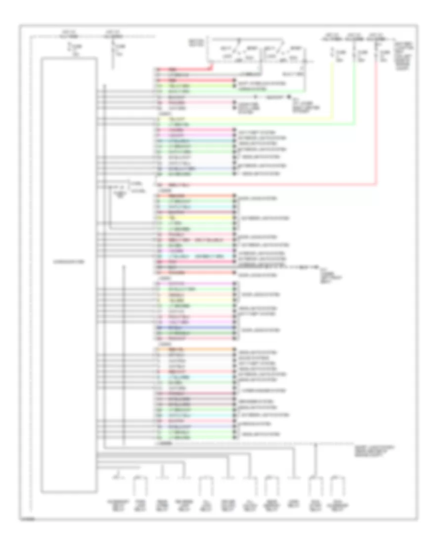
BODY CONTROL MODULES
Body Control Modules Wiring Diagram for Mazda Tribute s 2005
List of elements for Body Control Modules Wiring Diagram for Mazda Tribute s 2005:
- Acc
- Accessory delay relay
- All lock relay
- All unlock relay
- Anti-theft system
- Battery junction box (on left side of engine compt)
- Computer data lines system
- Defogger system
- Door locks system
- Driver unlock relay
- Exterior lights system
- Fuse 10a
- Fuse 15a
- Fuse 25a
- Fuse 40a
- Fuse 6 15a
- G11 (at lower right center of dash)
- G17 (under left front seat)
- Headlights system
- Horn relay
- Horns system
- Hot at all times
- Ignition switch
- Interior lights system
- J-2280a
- J-2280b
- J-2280c
- J-2280d
- J-2280e
- Lock
- Microcomputer
- Off
- Park lamp relay
- Pnk
- Rear defrost relay
- Rear wiper relay
- Red
- Reverse lamp relay
- Run
- Run/ accessory relay
- Run/ start relay
- Shift interlock system
- Smart junction box (rear center of engine compt)
- Sound systems
- Start
- W/drl
- W/o drl
- Warning system
- Wiper/washer system
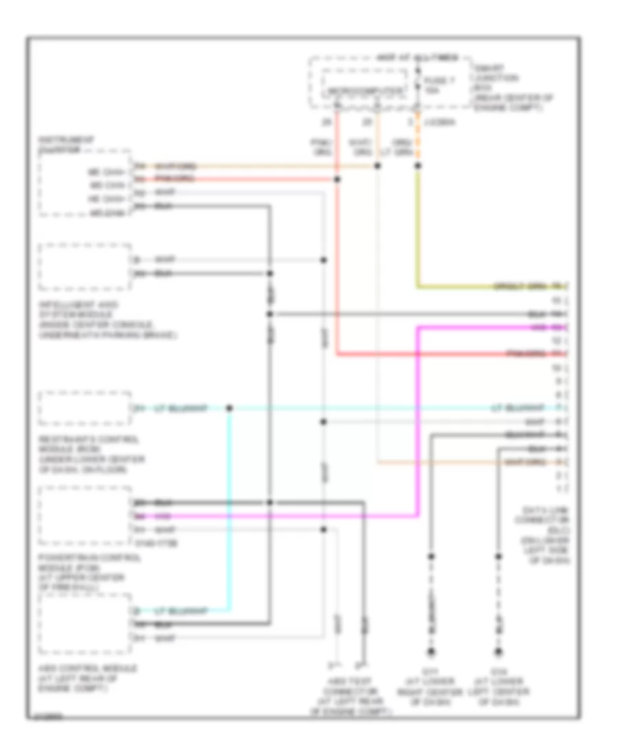
COMPUTER DATA LINES
Computer Data Lines Wiring Diagram for Mazda Tribute s 2005
List of elements for Computer Data Lines Wiring Diagram for Mazda Tribute s 2005:
- 0140-175b
- Abs control module (at left rear of engine compt)
- Abs test connector (at left rear of engine compt)
- Data link connector (dlc) (on lower left side of dash)
- Fuse 7 10a
- G11 (at lower right center of dash)
- G14 (at lower left center of dash)
- Hot at all times
- Hs can+
- Hs can-
- Instrument cluster
- Intelligent 4wd system module (inside center console, underneath parking brake)
- J-2280a
- Microcomputer
- Ms can+
- Ms can-
- Powertrain control module (pcm) (at upper center of firewall)
- Restraints control module (rcm) (under lower center of dash, on floor)
- Smart junction box (rear center of engine compt)
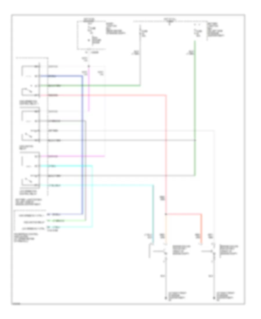
COOLING FAN
2.0L
2.0L, Cooling Fan Wiring Diagram for Mazda Tribute s 2005
List of elements for 2.0L, Cooling Fan Wiring Diagram for Mazda Tribute s 2005:
- (at right front of engine compartment) g2
- 0140-275b
- Battery junction box (on left side of engine compartment)
- Cooling fan relay
- Engine cooling fan motor 1 (front of engine compt)
- Engine cooling fan motor 2 (front of engine compt)
- Fuse 2a
- Fuse 40a
- High speed fan control relay 1
- High speed rly ctrl 1
- Hot at all times
- Hot in on or start
- J-2280b
- Low speed fan control relay
- Low speed rly ctrl
- Pcm power diode
- Powertrain control module (pcm) (at upper center of firewall)
- Smart junction box (rear center of engine compt)
3.0L
3.0L, Cooling Fan Wiring Diagram for Mazda Tribute s 2005
List of elements for 3.0L, Cooling Fan Wiring Diagram for Mazda Tribute s 2005:
- (at right front of engine compartment) g2
- 0140-275b
- 0140-275e
- 87a
- Battery junction box (on left side of engine compartment)
- Engine controls system
- Engine cool sens input
- Engine coolant temperature (ect) sensor (at right rear of engine)
- Engine cooling fan motor 1 (at left side of engine compartment, behind radiator)
- Engine cooling fan motor 2 (at right side of engine compartment, behind radiator)
- Fuse 2a
- Fuse 50a
- High speed fan control relay 1
- High speed fan control relay 2
- High speed rly ctrl 1
- Hot at all times
- Hot in on or start
- J-2280b
- Low speed fan control relay
- Low speed rly ctrl
- Pcm power diode
- Powertrain control module (pcm) (at upper center of firewall)
- Signal return
- Smart junction box (rear center of engine compt)
CRUISE CONTROL
Cruise Control Wiring Diagram for Mazda Tribute s 2005
List of elements for Cruise Control Wiring Diagram for Mazda Tribute s 2005:
- (2.3l) (3.0l)
- (not used)
- 0140-175b
- 0140-175b 0140-275b
- 0140-175t
- 0140-175t 0140-275t
- 2.3l: m/t
- 3.0l
- 3.0l, 2.3l: a/t
- Abs control module (at left rear of engine compt)
- Abs test connector (at left rear of engine compt)
- Air bag sliding contact (behind left side of dash)
- Brake pedal position switch (on bracket, above brake pedal)
- Clutch switch (2.3l: m/t)
- Coast
- Cruise control
- Deactivator switch
- Engine controls system
- Fuse 15a
- Fuse 5a
- G1 (at left rear of engine compt)
- G5 (at right front of engine compt)
- Hot at all times
- Hot in run or start
- Instrument cluster
- J-2280a
- J-2280b
- J-2280c
- J-2280d
- Nca
- Off
- Output shaft speed sensor (a/t) (on right rear of transmission, near left axle flange)
- Powertrain control module (at upper center of firewall)
- Resume
- Set/ accel
- Smart junction box (rear center of engine compt)
- Speed control servo (right rear of engine compt)
- Steering wheel/speed control switch
- Transmission range sensor (on left side of transmission)
- Turbine shaft speed sensor (a/t) (on right rear of transmission)
- Vehicle speed sensor (2.3l: m/t) (on right side of transmission)
DEFOGGERS
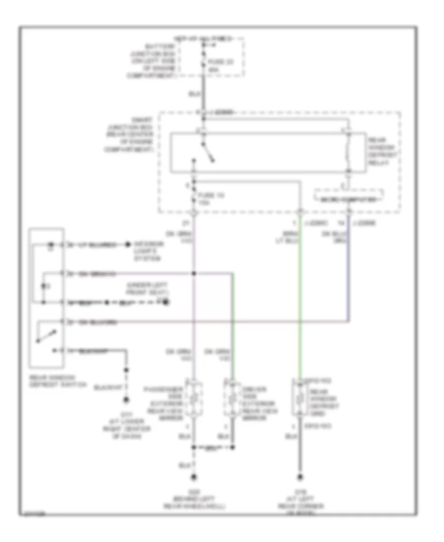
Defoggers Wiring Diagram for Mazda Tribute s 2005
List of elements for Defoggers Wiring Diagram for Mazda Tribute s 2005:
- (under left front seat) g15
- 0912-102
- 0912-103
- Battery junction box (on left side of engine compartment)
- Driver side exterior rear view mirror
- Fuse 10 15a
- Fuse 23 40a
- G11 (at lower right center of dash)
- G18 (at left rear corner of roof)
- G20 (behind left rear wheelwell)
- Hot at all times
- Interior lights system
- J-2280b
- J-2280c
- J-2280e
- Micro computer
- Passenger side exterior rear view mirror
- Rear window defrost grid
- Rear window defrost relay
- Rear window defrost switch
- Smart junction box (rear center of engine compartment)
ENGINE PERFORMANCE
2.3L
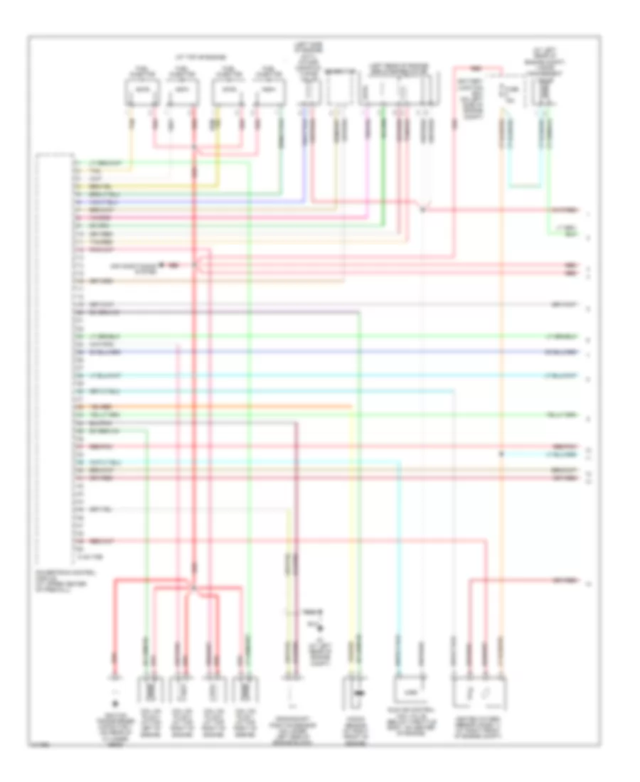
2.3L, Engine Performance Wiring Diagram (1 of 4) for Mazda Tribute s 2005
List of elements for 2.3L, Engine Performance Wiring Diagram (1 of 4) for Mazda Tribute s 2005:
- (at left rear of engine compt) vapor management valve
- (at top of engine)
- (left rear of engine) egr stepper motor
- (left side of engine) (imtv) intake manifold tuning valve
- 0140-175e
- Air conditioning system
- Battery junction box (on left side of engine compt)
- Coil on plug 1 (at top right of engine)
- Coil on plug 2 (at top right of engine)
- Coil on plug 3 (at top right of engine)
- Coil on plug 4 (at top left of engine)
- Crankshaft position sensor (on lower left side of engine block)
- Fuel injector
- Fuse 15a
- G1 (at left rear of engine compt)
- Generator
- Heated oxygen sensor (ho2s) 11 (at right front of engine compt)
- Idle air control (iac) valve (below throttle body, on center of engine)
- Ignition transformer capacitor 1 (on rear of cylinder head)
- Knock sensor (at right front of engine)
- Nca
- Powertrain control module (at upper center of firewall)
- Red
- Red/pnk
- Tan
- Tan/red
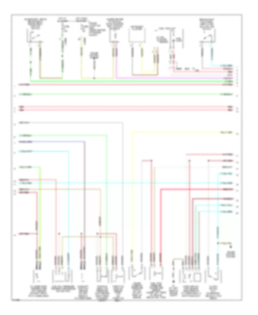
2.3L, Engine Performance Wiring Diagram (2 of 4) for Mazda Tribute s 2005
List of elements for 2.3L, Engine Performance Wiring Diagram (2 of 4) for Mazda Tribute s 2005:
- (behind right kick panel) inertia fuel shutoff (ifs) switch
- (on bracket, above brake pedal) brake pedal position switch
- (under center of vehicle) evap canister vent control solenoid
- Camshaft position sensor (on left rear of cylinder head)
- Clutch switch (m/t) (on bracket, above clutch pedal)
- Cruise control system
- Cylinder head temperature (cht) sensor (on right front of cylinder head)
- Fuel gauge sensor
- Fuel pump
- Fuel rail pressure/ temperature sensor (on fuel rail)
- Fuel tank pressure transducer sensor (under left rear of vehicle, above fuel tank)
- Fuel tank unit
- Fuse 15a
- Fuse 5a
- G1 (at left rear of engine compt)
- G22
- Hot at all times
- Hot in run or start
- Instrument cluster
- J-2280c
- J-2280d
- Manifold absolute pressure (map) sensor (right rear of engine compt)
- Mass airflow (maf) sensor (near rear of cylinder head, in air intake duct)
- Nca
- Power steering pressure switch (on left front of engine)
- Red
- Red/pnk
- Smart junction box (rear center of engine compt)
- Throttle position sensor (tps) (on throttle body)
2.3L, Engine Performance Wiring Diagram (3 of 4) for Mazda Tribute s 2005
List of elements for 2.3L, Engine Performance Wiring Diagram (3 of 4) for Mazda Tribute s 2005:
- (at left rear of engine compt) g1
- (left rear wheelwell) fuel pump driver module
- 0140-175b
- 0914-201
- Air condi- tioning system
- Battery junction box (on left side of engine compt)
- Cooling fans system
- Data link connector (dlc) (on lower left side of dash)
- Fuel pump relay
- Fuse 10a
- Fuse 20a
- Fuse 2a
- Fuse 30a
- Fuse 5a
- G20 (behind left rear wheelwell)
- G22
- G9 (at rear of engine)
- Hot at all times
- Hot in run or start
- J-2280b
- Passive anti-theft transceiver (behind lower left side of dash, near steering column)
- Pcm power diode
- Pcm power relay
- Powertrain control module (at upper center of firewall)
- Red
- Red/pnk
- Smart junction box (rear center of engine compt)
- Starting/ charging system
2.3L, Engine Performance Wiring Diagram (4 of 4) for Mazda Tribute s 2005
List of elements for 2.3L, Engine Performance Wiring Diagram (4 of 4) for Mazda Tribute s 2005:
- (at right side of engine compartment)
- (left front of engine compt) (a/t) transmission hardware unit
- (on left side of transmission)
- (on right side of transmission) (m/t) vehicle speed sensor
- 0140-175t
- A/t
- Electronic pressure control solenoid
- Floor shifter
- Fuse 10a
- Heated oxygen sensor (ho2s) 12
- Hot w/ run or start relay energized
- J-2280-a
- M/t
- O/d switch
- Output shaft speed (oss) sensor (a/t) (on right rear of transmission, near left axle flange)
- Powertrain control module (at upper center of firewall)
- Shift solenoid a
- Shift solenoid b
- Shift solenoid c
- Smart junction box (rear center of engine compt)
- Torque converter clutch solenoid
- Transmission fluid temperature sensor
- Transmission range (tr) sensor
- Turbine shaft speed (tss) sensor (a/t)
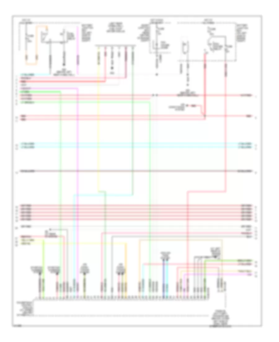
3.0L
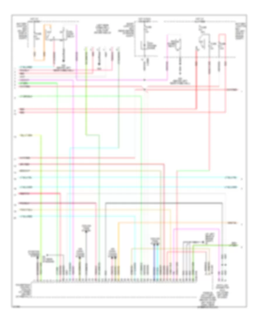
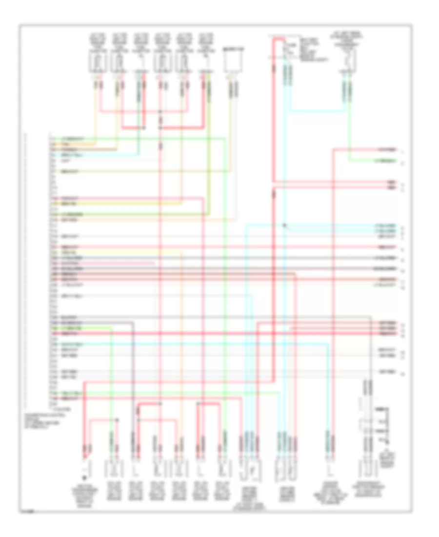
3.0L, Engine Performance Wiring Diagram (1 of 4) for Mazda Tribute s 2005
List of elements for 3.0L, Engine Performance Wiring Diagram (1 of 4) for Mazda Tribute s 2005:
- (at left rear of engine compt) vapor management valve
- (at top left of engine) fuel injector
- (at top right of engine) fuel injector
- 0140-275e
- Battery junction box (on left side of engine compt)
- Coil on plug 1 (at top right of engine)
- Coil on plug 2 (at top right of engine)
- Coil on plug 3 (at top right of engine)
- Coil on plug 4 (at top left of engine)
- Coil on plug 5 (at top left of engine)
- Coil on plug 6 (at top left of engine)
- Crankshaft position sensor (at front of engine block)
- Fuse 15a
- G1 (at left rear of engine compt)
- Generator
- Heated oxygen sensor (ho2s) 11 (at right side of engine compt)
- Heated oxygen sensor (ho2s) 21
- Idle air control (iac) valve (below throttle body, at rear of engine)
- Ignition transformer capacitor 1 (on right front of engine)
- Nca
- Powertrain control module (at upper center of firewall)
- Red
- Red/pnk
- Tan
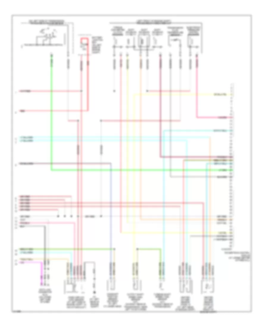
3.0L, Engine Performance Wiring Diagram (2 of 4) for Mazda Tribute s 2005
List of elements for 3.0L, Engine Performance Wiring Diagram (2 of 4) for Mazda Tribute s 2005:
- (behind right kick panel) inertia fuel shutoff (ifs) switch
- (not used)
- (on bracket, above brake pedal) brake pedal position switch
- (under center of vehicle) evap canister vent control solenoid
- C-248
- Cruise control system
- Differential pressure egr vacuum regulator (top rear of engine)
- Differential pressure feedback egr sensor (on right rear of engine)
- Engine coolant temperature (ect) sensor (at right rear of engine)
- Floor shifter
- Fuel gauge sensor
- Fuel pump
- Fuel tank pressure transducer sensor (under left left rear of vehicle, above fuel tank)
- Fuel tank unit
- Fuse 10a
- Fuse 15a
- Fuse 5a
- G22
- Hot at all times
- Hot in run or start
- Hot w/ run or start relay energized
- Injector pressure sensor (front of engine assembly)
- Instrument cluster
- J-2280-a
- J-2280-c
- J-2280d
- Manifold absolute pressure (map) sensor (right rear of engine compt)
- Nca
- O/d switch
- Power steering pressure switch (on left front of engine)
- Red
- Red/pnk
- Smart junction box (rear center of engine compt)
- Throttle position sensor (tps) (on throttle body)
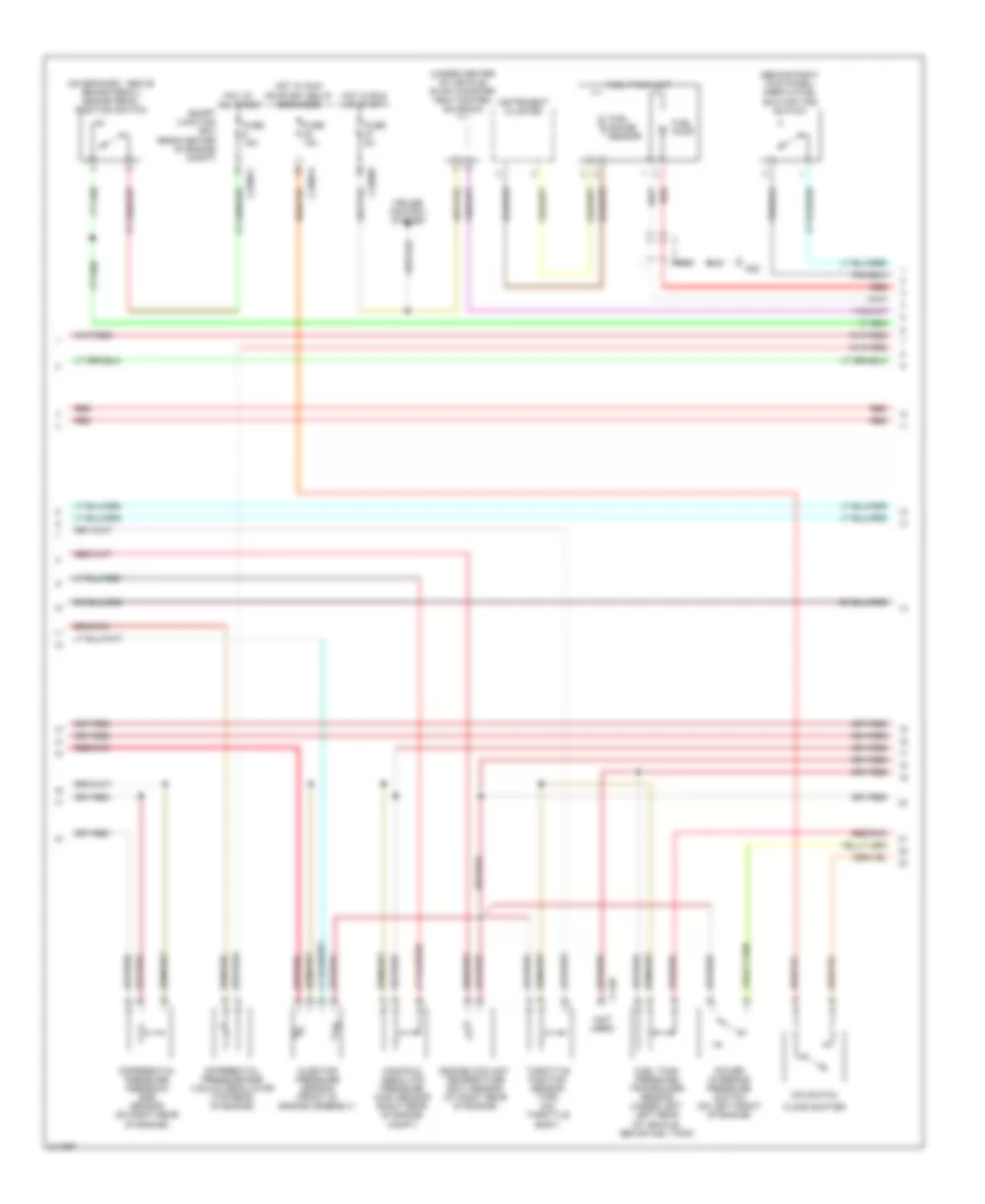
3.0L, Engine Performance Wiring Diagram (3 of 4) for Mazda Tribute s 2005
List of elements for 3.0L, Engine Performance Wiring Diagram (3 of 4) for Mazda Tribute s 2005:
- (at left rear of engine compt) g1
- (left rear wheelwell) fuel pump driver module
- 0140-275b
- 0914-201
- Air condi- tioning system
- Air conditioning system
- Battery junction box (on left side of engine compt)
- Cooling fans system
- Fuel pump relay
- Fuse 20a
- Fuse 2a
- Fuse 30a
- Fuse 5a
- G20 (behind left rear wheelwell)
- G22
- G9 (at rear of engine)
- Hot at all times
- Hot in run or start
- J-2280b
- Passive anti-theft transceiver (behind lower left side of dash, near steering column)
- Pcm power diode
- Pcm power relay
- Powertrain control module (at upper center of firewall)
- Red
- Red/pnk
- Smart junction box (rear center of engine compt)
- Starting/ charging system
- Tan/red
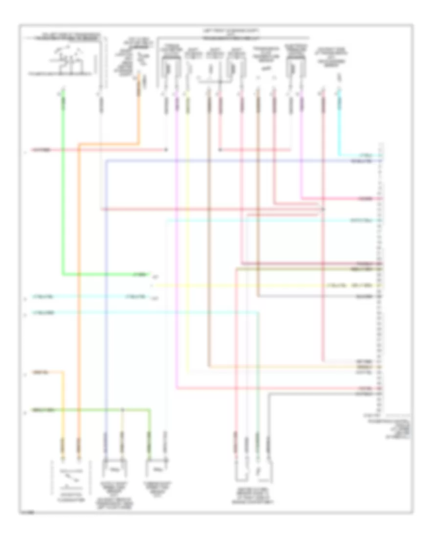
3.0L, Engine Performance Wiring Diagram (4 of 4) for Mazda Tribute s 2005
List of elements for 3.0L, Engine Performance Wiring Diagram (4 of 4) for Mazda Tribute s 2005:
- (left front of engine compt) transmission hardware unit
- (on left side of transmission) transmission range sensor
- 0140-275t
- Battery junction box (on left side of engine compt)
- Camshaft position sensor (on front of left cylinder head)
- Data link connector (dlc) (on lower left side of dash)
- Electronic pressure control solenoid
- Fuse 10a
- G1 (at left rear of engine compt)
- Heated oxygen sensor (ho2s) 12 (at left rear of engine compt)
- Heated oxygen sensor (ho2s) 22 (at left front of engine compt)
- Mass airflow (maf) sensor (at left side of engine compt, in air intake duct)
- Output shaft speed (oss) sensor (a/t) (on right rear of transmission, near left axle flange)
- Powertrain control module (at upper center of firewall)
- Red
- Shift solenoid a
- Shift solenoid b
- Shift solenoid c
- Torque converter clutch solenoid
- Transmission fluid temperature sensor
- Turbine shaft speed (tss) sensor (a/t) (on right rear of transmission)
EXTERIOR LIGHTS
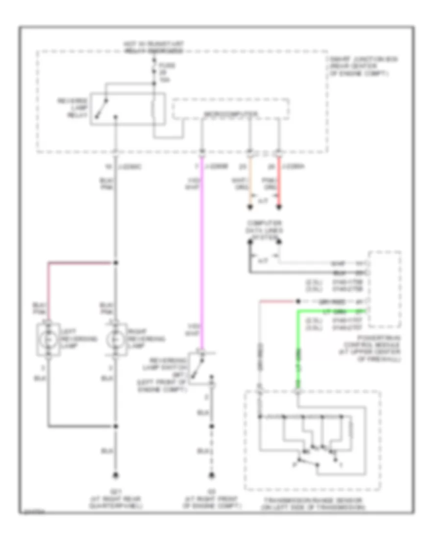
Back-up Lamps Wiring Diagram for Mazda Tribute s 2005
List of elements for Back-up Lamps Wiring Diagram for Mazda Tribute s 2005:
- (2.3l) (3.0l)
- 0140-175b 0140-275b
- 0140-175t 0140-275t
- A/t
- Computer data lines system
- Fuse 10a
- G21 (at right rear quarterpanel)
- G5 (at right front of engine compt)
- Hot w/ run/start relay energized
- J-2280a
- J-2280b
- J-2280c
- Left reversing lamp
- Microcomputer
- Powertrain control module (at upper center of firewall)
- Reverse lamp relay
- Reversing lamp switch (m/t) (left front of engine compt)
- Right reversing lamp
- Smart junction box (rear center of engine compt)
- Transmission range sensor (on left side of transmission)
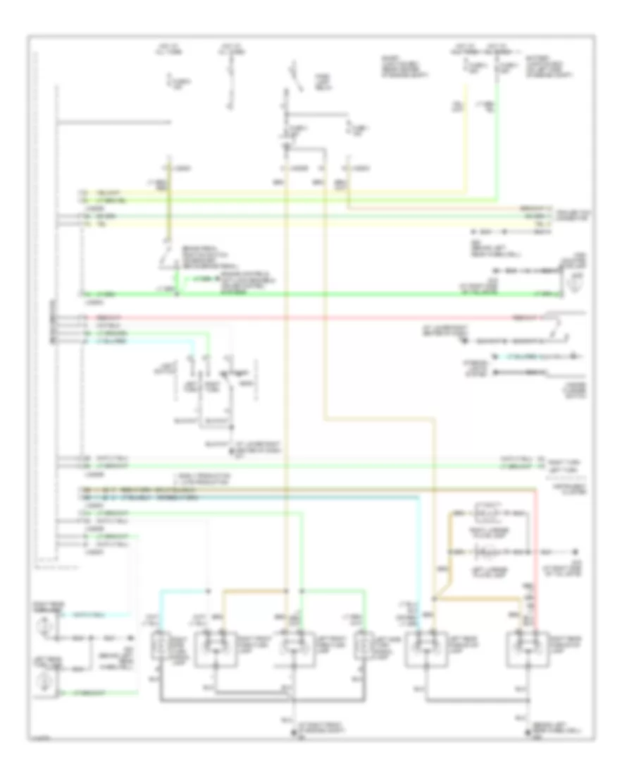
Exterior Lamps Wiring Diagram for Mazda Tribute s 2005
List of elements for Exterior Lamps Wiring Diagram for Mazda Tribute s 2005:
- (4)
- (at lower right center of dash) g11
- (at right front of engine compt) g5
- (behind left rear wheelwell) g20
- (or lt
- Battery junction box (on left side of engine compt)
- Brake pedal position switch (on bracket, above brake pedal)
- Early production
- Engine controls, anti-lock brakes & cruise control systems
- Fuse 1 15a
- Fuse 2 25a
- Fuse 3 15a
- Fuse 3 25a
- Fuse 6 15a
- G19 (at right side of tail gate)
- G20 (behind left rear wheelwell)
- Hazard flasher switch
- Head
- High mounted stoplamp
- Hot at all times
- Instrument cluster
- Interior lights system
- J-2280b
- J-2280c
- J-2280e
- Late production
- Left front park/turn lamp
- Left license plate lamp
- Left rear park/stop lamp
- Left rear turn lamp
- Left side turn signal lamp
- Left turn
- Light switch
- Lom
- Microcomputer
- Off
- Park
- Park lamp relay
- Right front park/turn lamp
- Right license plate lamp
- Right rear park/stop lamp
- Right rear turn lamp
- Right side turn signal lamp
- Right turn
- Smart junction box (rear center of engine compt)
- Trailer tow connector
GROUND DISTRIBUTION
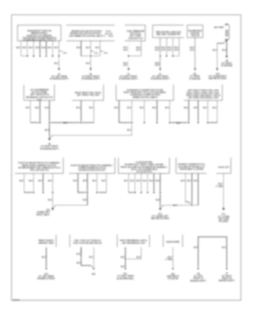
Ground Distribution Wiring Diagram (1 of 2) for Mazda Tribute s 2005
List of elements for Ground Distribution Wiring Diagram (1 of 2) for Mazda Tribute s 2005:
- (2.4l), (2.4l) &
- (3.0l)
- (m/t)
- 2.3l
- 3.0l
- A/c compressor clutch diode, left headlamp &
- Abs control module & abs test connector
- Audio unit
- Battery
- Crankshaft position sensor shield, mass air flow sensor, transmission range sensor & powertrain control module
- Duel pressure switch & anti-theft hood switch
- Engine cooling fan motor 1
- Engine cooling fan motor 2
- Floor shifter, power point, front cigar lighter, front blower motor resistor assembly, data link connector & a/c on switch
- Fuel tank unit shield & fuel pump driver module
- Function selector switch assembly rear window defrost switch, exterior rear view mirror switch & fog lamp switch
- Function selector switch assembly, wiper/washer switch & air bag sliding contact
- G1 (at left rear of engine compt)
- G10 (at lower right center of dash)
- G13 (at lower left side of dash)
- G14 (at lower left center of dash)
- G15 (under left front seat)
- G18 (at left rear corner of roof)
- G2 (at right front of engine compt)
- G21 (at right rear quarterpanel)
- G22
- G23 (center of tailgate)
- G3 (at right front of engine compt)
- G4 (at left front of engine compt)
- G5 (at right front of engine compt)
- G6 (at left front of engine compt)
- G7 (at right front of engine compt)
- G8 (at front of engine)
- G9 (at rear of engine)
- Hazard flasher switch, blower motor relay & instrument cluster
- High speed fan control relay 2
- Left front park/turn lamp, right front park/turn lamp, right side turn signal lamp & left side turn signal lamp
- Nca
- Powertrain control module
- Rear window defrost grid
- Reversing lamp switch
- Right front fog lamp & left front fog lamp
- Right reversing lamp & left reversing lamp
- Subwoofer
- Windshield washer pump motor, right headlamp, a/c clutch solenoid, windshield wiper motor & speed control servo
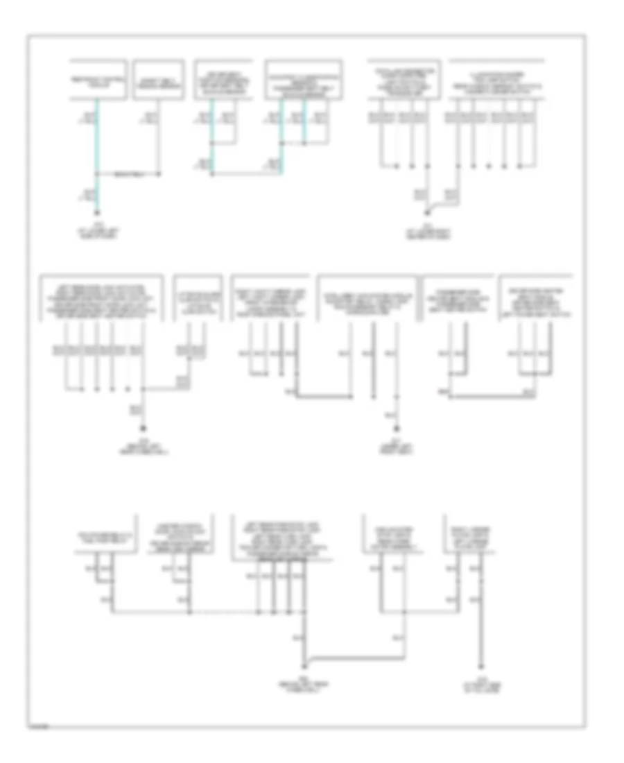
Ground Distribution Wiring Diagram (2 of 2) for Mazda Tribute s 2005
List of elements for Ground Distribution Wiring Diagram (2 of 2) for Mazda Tribute s 2005:
- Data link connector, micro computer, light switch & passive anti-theft transceiver
- Driver seat position sensor & driver seat belt buckle sensor
- Driver side heated seat module, driver side seat heater switch & left power seat switch
- G11 (at lower right center of dash)
- G12 (at lower left side of dash)
- G16 (behind left rear wheelwell)
- G17 (under left front seat)
- G19 (at right side of tail gate)
- G20 (behind left rear wheelwell)
- High mounted stop lamp & rear wiper motor assembly
- Illumination dimmer, fog lamp switch, rear window defrost switch & hazard flasher switch
- Intelligent 4wd system module,
- Left rear door lock actuator, right rear door lock actuator, passenger side front door lock unit, driver side front door lock unit, passenger side seat heater switch & driver side seat heater switch
- Left rear park/stop lamp, right rear park/stop lamp, left rear turn lamp, right rear turn lamp, trailer connector turn lamp & passenger side exterior rear view mirror
- Liftgate glass ajar switch & liftgate ajar switch
- Master window door lock/unlock switch & driver side exterior rear view mirror
- Occupant classification sensor & passenger seat belt buckle sensor
- Passenger side heated seat module & passenger side seat heater switch
- Pcm power relay & fuel pump relay
- Restraint control module
- Right license plate lamp & left license plate lamp
- Right vanity mirror lamp, left vanity mirror lamp, front interior/map lamps assembly & roof opening panel unit
- Run/start relay, cargo lamp, run/accessory relay & microcomputer
- Safety belt tension sensor
HEADLIGHTS
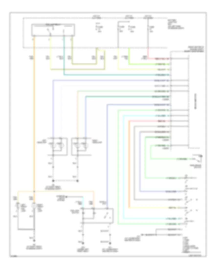
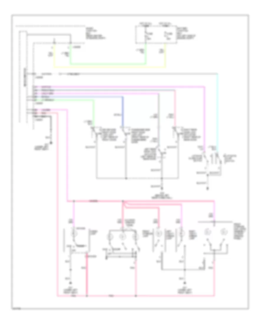
Headlights Wiring Diagram, with DRL for Mazda Tribute s 2005
List of elements for Headlights Wiring Diagram, with DRL for Mazda Tribute s 2005:
- (rear center of engine compt) smart junction box
- 0 off 1 park 2 low 3 high 4 headlamps 5 flash to pass 6 left 7 right
- 20a
- 25a
- 40a
- Battery junction box (on left side of engine compt)
- Fog lamp relay
- Fog lamp switch
- Fuse
- G11 (at lower right center of dash)
- G15 (under left front seat)
- G5 (at right front of engine compt)
- High
- Hot at all times
- Interior lights system
- J-2280b
- J-2280d
- J-2280e
- Left front fog lamp
- Left headlamp
- Light switch
- Low
- Microcomputer
- Park brake switch
- Right front fog lamp
- Right headlamp
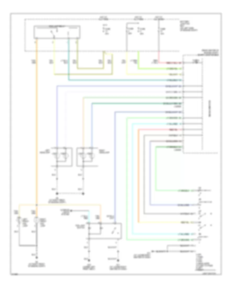
Headlights Wiring Diagram, without DRL for Mazda Tribute s 2005
List of elements for Headlights Wiring Diagram, without DRL for Mazda Tribute s 2005:
- (rear center of engine compt) smart junction box
- 0 off 1 park 2 low 3 high 4 headlamps 5 flash to pass 6 left 7 right
- 20a
- 25a
- 40a
- Battery junction box (on left side of engine compt)
- Fog lamp relay
- Fog lamp switch
- Fuse
- Fuse 6 15a
- G11 (at lower right center of dash)
- G15 (under left front seat)
- G5 (at right front of engine compt)
- High
- Hot at all times
- Interior lights system
- J-2280b
- J-2280e
- Left front fog lamp
- Left headlamp
- Light switch
- Low
- Microcomputer
- Right front fog lamp
- Right headlamp
HORN
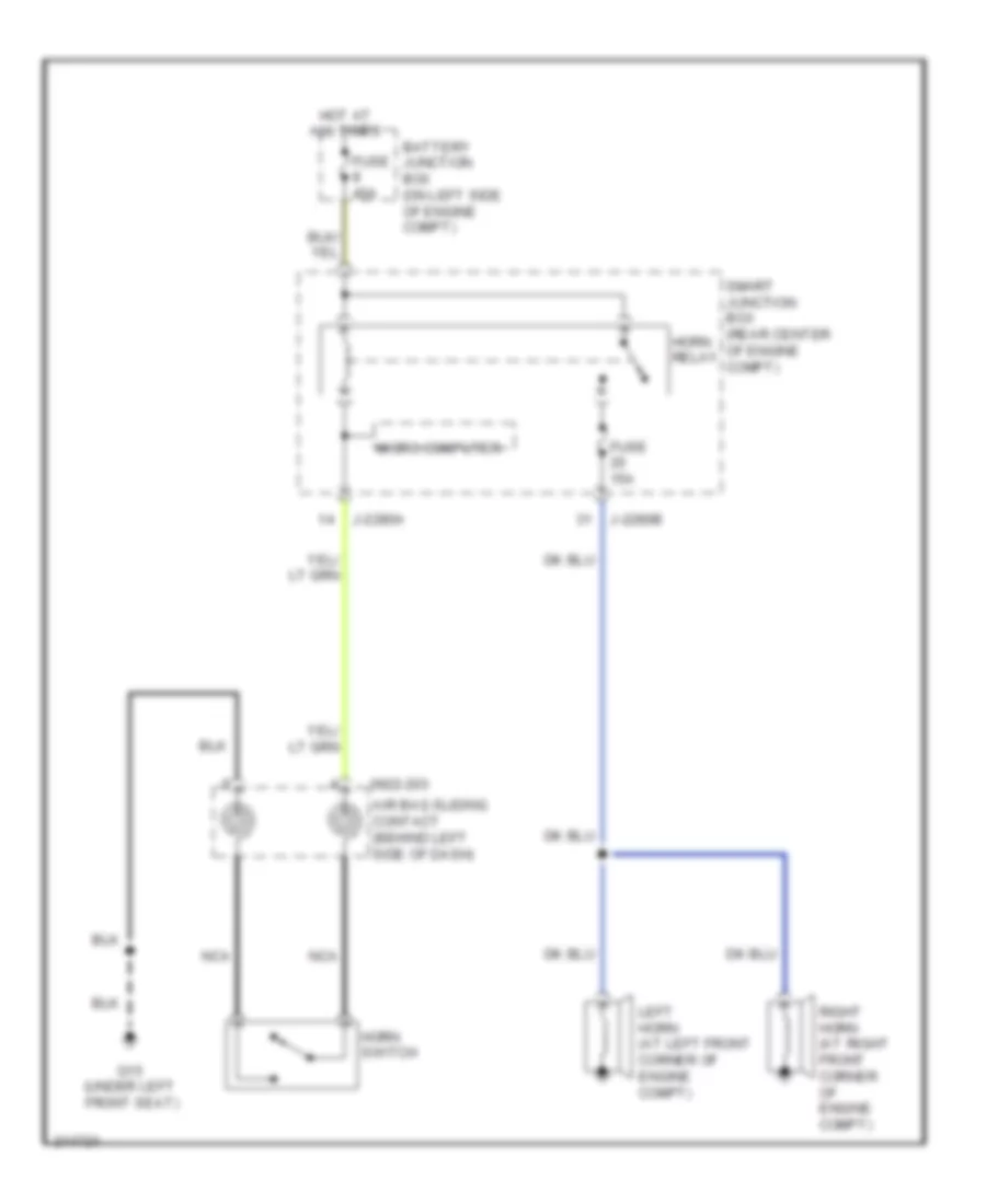
Horn Wiring Diagram for Mazda Tribute s 2005
List of elements for Horn Wiring Diagram for Mazda Tribute s 2005:
- 0922-203
- Air bag sliding contact (behind left side of dash)
- Battery junction box (on left side of engine compt)
- Fuse 15a
- Fuse 40a
- G15 (under left front seat)
- Horn switch
- Horn relay
- Hot at all times
- J-2280a
- J-2280b
- Left horn (at left front corner of engine compt)
- Micro computer
- Nca
- Right horn (at right front corner of engine compt)
- Smart junction box (rear center of engine compt)
INSTRUMENT CLUSTER
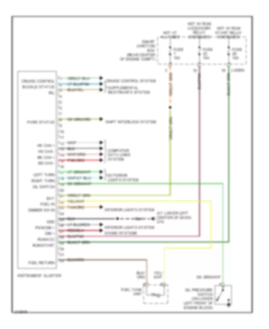
Instrument Cluster Wiring Diagram for Mazda Tribute s 2005
List of elements for Instrument Cluster Wiring Diagram for Mazda Tribute s 2005:
- (at lower left center of dash) g14
- Bat
- Buckle status
- Computer data lines system
- Cruise control
- Cruise control system
- Dim +
- Dimmer sw in
- Exterior lights system
- Fuel in
- Fuel return
- Fuel tank unit
- Fuse 10a
- Gnd
- Hot at all times
- Hot w/ run/ accessory relay energized
- Hot w/ run/ start relay energized
- Hs can +
- Hs can -
- Instrument cluster
- Interior lights system
- J-2280a
- Left turn
- Ms can +
- Ms can -
- Oil pressure switch (on lower left front of engine block)
- Oil switch
- Park status
- Pwm dim +
- Right turn
- Ril
- Run/acc
- Run/start
- Shift interlock system
- Smart junction box (rear center of engine compt)
- Sound systems
INTERIOR LIGHTS
Courtesy Lamps Wiring Diagram for Mazda Tribute s 2005
List of elements for Courtesy Lamps Wiring Diagram for Mazda Tribute s 2005:
- 0918-805
- 0918-806
- Ajar
- Battery junction box (on left side of engine compt)
- Cargo lamp
- Door
- Driver side front door lock unit (left rear of front door)
- Front interior lamp
- Front interior/ map lamps assembly (w/ roof opening panel)
- Fuse 25a
- G16 (behind left rear wheelwell)
- G17 (under left front seat)
- Hot at all times
- J-2280b
- J-2280c
- J-2280d
- J-2280e
- Left rear door lock actuator (left rear of rear door)
- Left vanity mirror lamp
- Liftgate ajar switch
- Liftgate glass ajar switch
- Microcomputer
- Off
- Passenger side front door lock unit (front rear of passenger's door)
- Pnk
- Right rear door lock actuator (right rear of rear door)
- Right vanity mirror lamp
- Smart junction box (rear center of engine compt)
- W/o roof opening panel
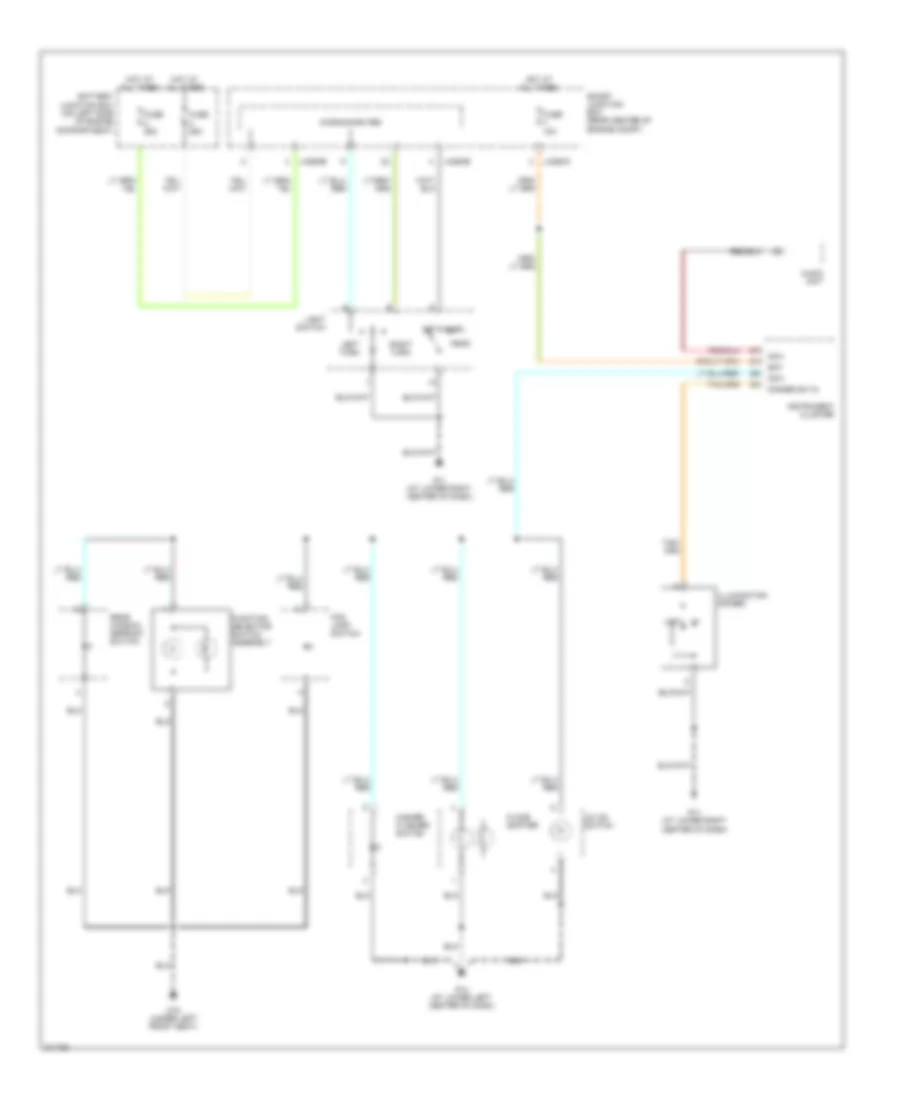
Instrument Illumination Wiring Diagram for Mazda Tribute s 2005
List of elements for Instrument Illumination Wiring Diagram for Mazda Tribute s 2005:
- A/c on switch
- Audio unit
- Bat
- Battery junction box (on left side of engine compartment)
- Dim+
- Dimmer sw in
- Floor shifter
- Fog lamp switch
- Function selector switch assembly
- Fuse 10a
- Fuse 25a
- G11 (at lower right center of dash)
- G14 (at lower left center of dash)
- G15 (under left front seat)
- Hazard flasher switch
- Head
- Hot at all times
- Illumination dimmer
- Instrument cluster
- J-2280a
- J-2280b
- J-2280e
- Left turn
- Light switch
- Low
- Microcomputer
- Off
- Park
- Rear window defrost switch
- Right turn
- Smart junction box (rear center of engine compt)
POWER DISTRIBUTION
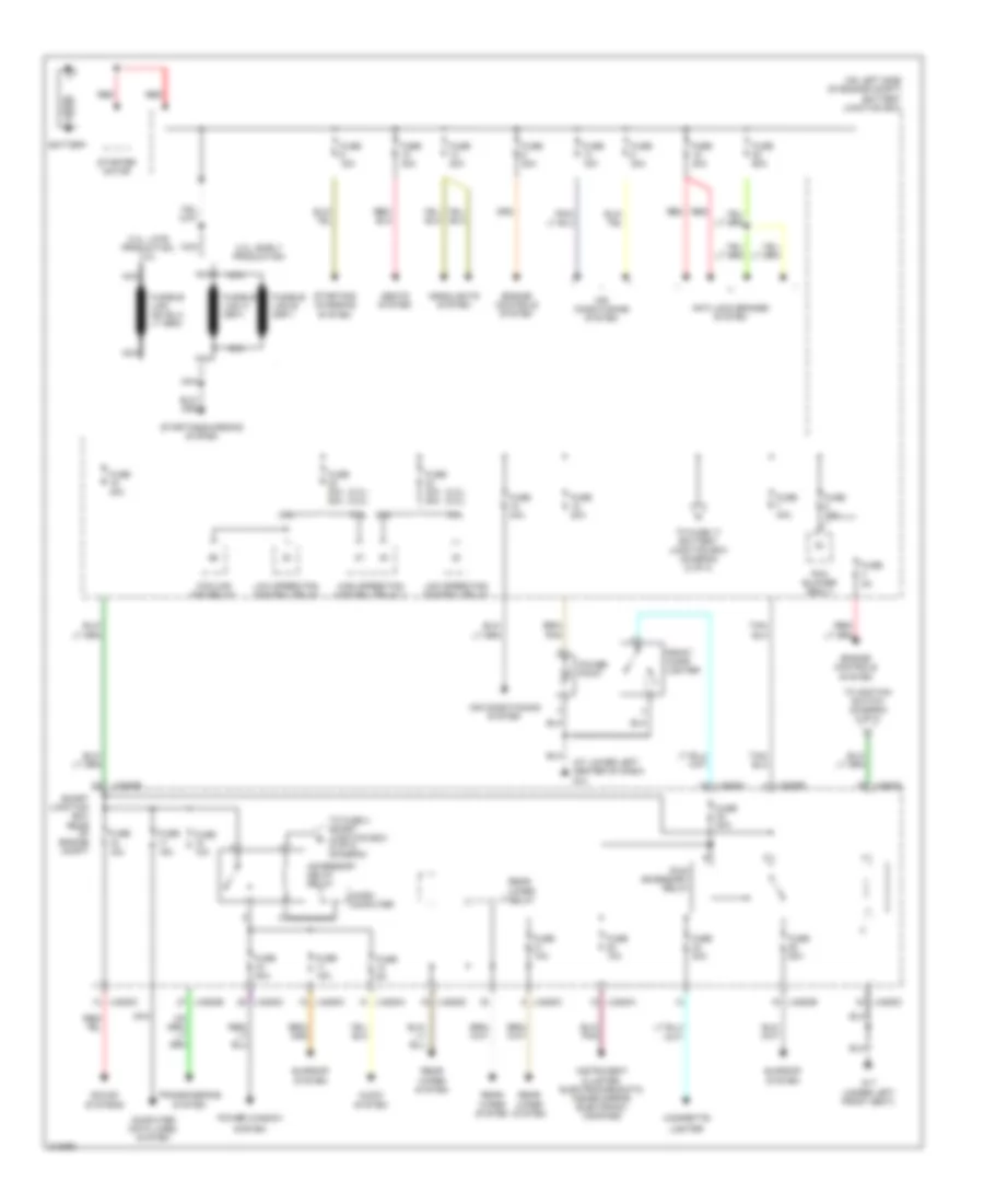
Power Distribution Wiring Diagram (1 of 2) for Mazda Tribute s 2005
List of elements for Power Distribution Wiring Diagram (1 of 2) for Mazda Tribute s 2005:
- (2.3l) (3.0l)
- (at lower left center of dash) g14
- (on left side of engine compt) battery junction box
- 2.3l
- 2.3l: early production
- 2.3l: late production, 3.0l
- 3.0l
- Accessory delay relay
- Air conditioning system
- Anti-lock brakes system
- Audio system
- Battery
- Cigarette
- Computer data lines system
- Cooling fan relay
- Engine controls system
- Front cigar lighter
- Fuse 10a
- Fuse 15a
- Fuse 20a
- Fuse 30a
- Fuse 40a
- Fuse 40a 50a
- Fuse 5a
- Fuse 60a
- G17 (under left front seat)
- Headlights system
- High speed fan control relay 1
- Instrument cluster, electrochromatic inside mirror, electronic compass
- J-2280a
- J-2280b
- J-2280c
- J-2280d
- Lighter
- Low speed fan control relay
- Micro computer
- Nca
- Pcm blower realy
- Power point
- Power window
- Rear wiper relay
- Rear wiper system
- Red
- Run/ accessory relay
- Seats system
- Smart junction box rear of engine compt
- Sound systems
- Starter motor
- Starting/ charging system
- Starting/charging system
- Sunroof system
- System
- To fuse 17 battery junction box (diagram (2 of 2)
- To fuse 4 smart junction box (2 of 2) (diagram
- To ignition switch (diagram 2 of 2)
- Transmissions system
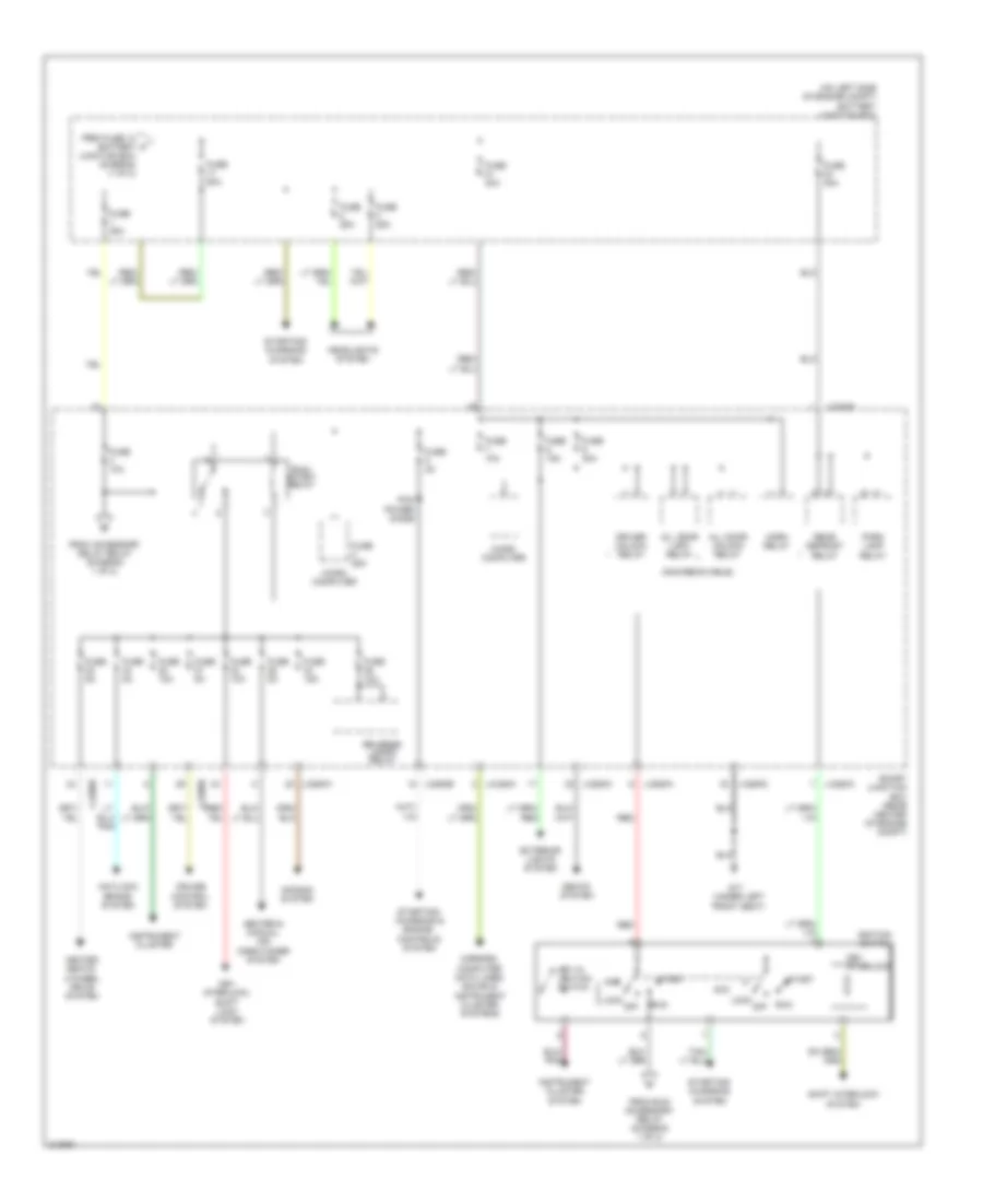
Power Distribution Wiring Diagram (2 of 2) for Mazda Tribute s 2005
List of elements for Power Distribution Wiring Diagram (2 of 2) for Mazda Tribute s 2005:
- (non-removable)
- (on left side of engine compt) battery junction box
- (under left front seat)
- Acc
- Air bag system
- All door lock relay
- All door unlock relay
- Antilock brake system
- Cruise control system
- Driver unlock relay
- Exterior lights system
- From accessory delay relay (diagram 1 of 2)
- From fuse 12 a battery junction box (diagram (1 of 2)
- From run/ accessory relay (diagram 1 of 2)
- Fuse 10a
- Fuse 15a
- Fuse 25a
- Fuse 2a
- Fuse 30a
- Fuse 40a
- Fuse 50a
- Fuse 5a
- G17
- Headlights system
- Heated seats, 4-wheel drive system
- Heater & manual air conditioner system
- Horn relay
- Ignition switch
- Instrument cluster
- Instrument cluster system
- J-2280a
- J-2280b
- J-2280c
- J-2280d
- Key in ignition switch
- Key interlock
- Key interlock, shift lock system
- Lock off
- Micro computer
- Mirrors, computer data lines, sound & instrument cluster systems
- Park lamp relay
- Pcm power diode
- Rear defrost relay
- Red
- Reverse lamps relay
- Run
- Run/ start relay
- Seats system
- Shift interlock system
- Smart junction box (rear center of engine compt)
- Start
- Starting/ charging & engine controls system
- Starting/ charging system
POWER MIRRORS
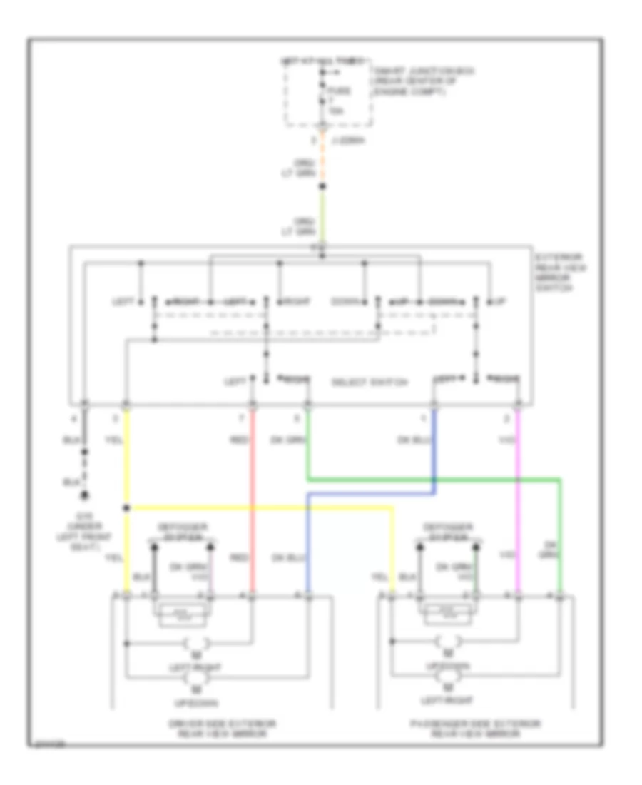
Power Mirrors Wiring Diagram for Mazda Tribute s 2005
List of elements for Power Mirrors Wiring Diagram for Mazda Tribute s 2005:
- Defogger system
- Down
- Driver side exterior rear view mirror
- Exterior rear view mirror switch
- Fuse 10a
- G15 (under left front seat)
- Hot at all times
- J-2280a
- Left
- Left/right
- Passenger side exterior rear view mirror
- Red
- Right
- Select switch
- Smart junction box (rear center of engine compt)
- Up/down
POWER SEATS
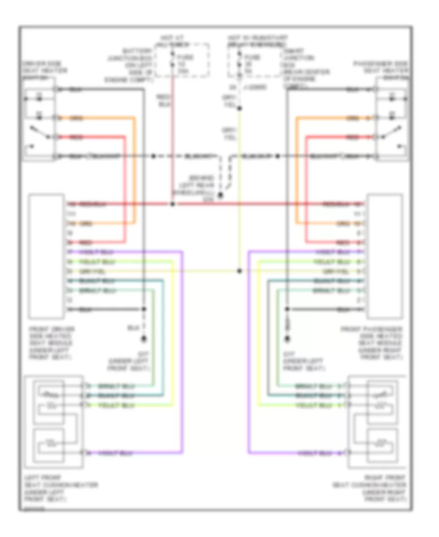
Heated Seats Wiring Diagram for Mazda Tribute s 2005
List of elements for Heated Seats Wiring Diagram for Mazda Tribute s 2005:
- (behind left rear wheelwell) g16
- Battery junction box (on left side of engine compt)
- Driver side seat heater switch
- Front driver side heated seat module (under left front seat)
- Front passenger side heated seat module (under right front seat)
- Fuse 30a
- Fuse 5a
- G17 (under left front seat)
- Hot at all times
- Hot w/ run/start relay energized
- J-2280d
- Left front seat cushion heater (under left front seat)
- Passenger side seat heater switch
- Red
- Right front seat cushion heater (under right front seat)
- Smart junction box (rear center of engine compt)
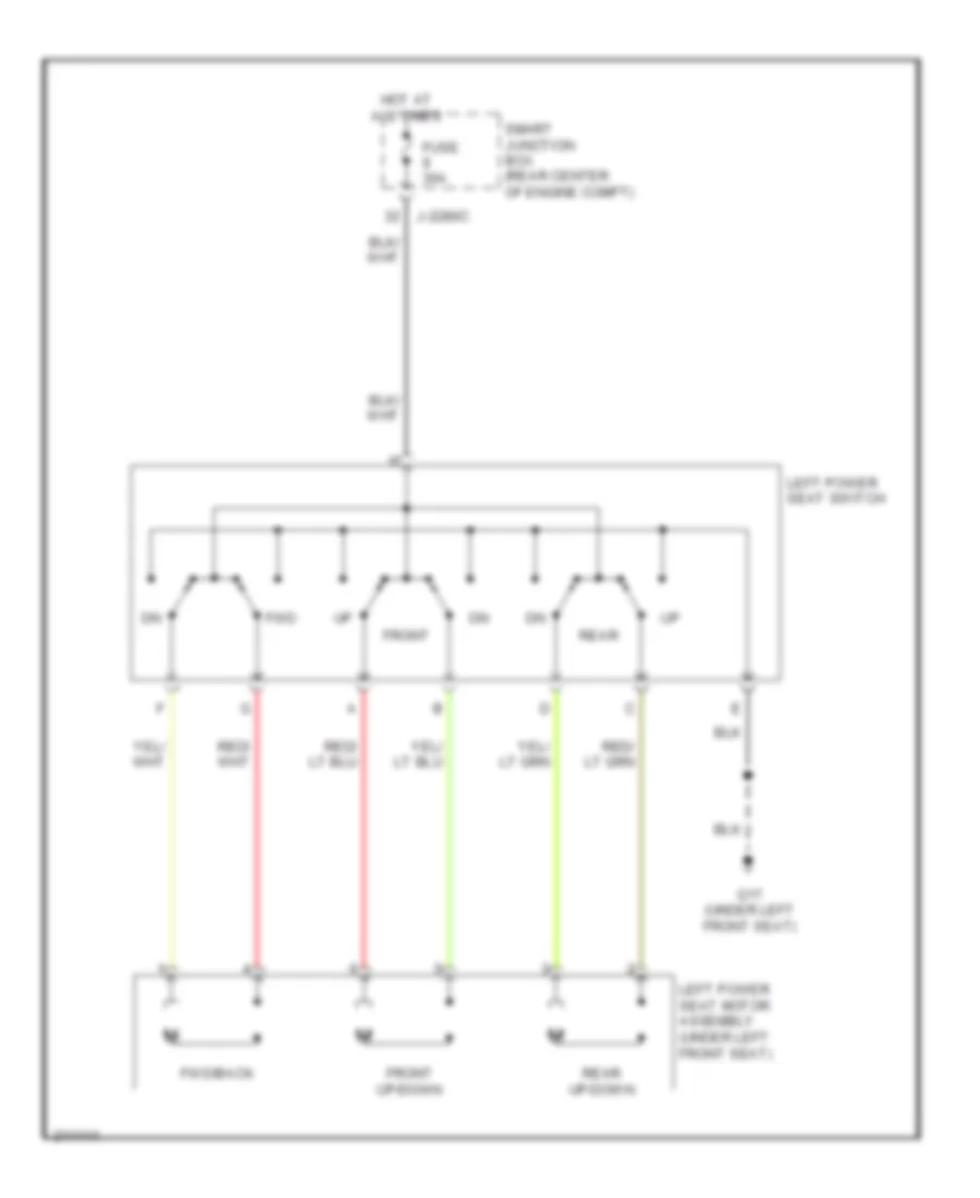
Power Seat Wiring Diagram for Mazda Tribute s 2005
List of elements for Power Seat Wiring Diagram for Mazda Tribute s 2005:
- Front
- Front up/down
- Fuse 30a
- Fwd
- Fwd/back
- G17 (under left front seat)
- Hot at all times
- J-2280c
- Left power seat motor assembly (under left front seat)
- Left power seat switch
- Rear
- Rear up/down
- Smart junction box (rear center of engine compt)
POWER TOP/SUNROOF
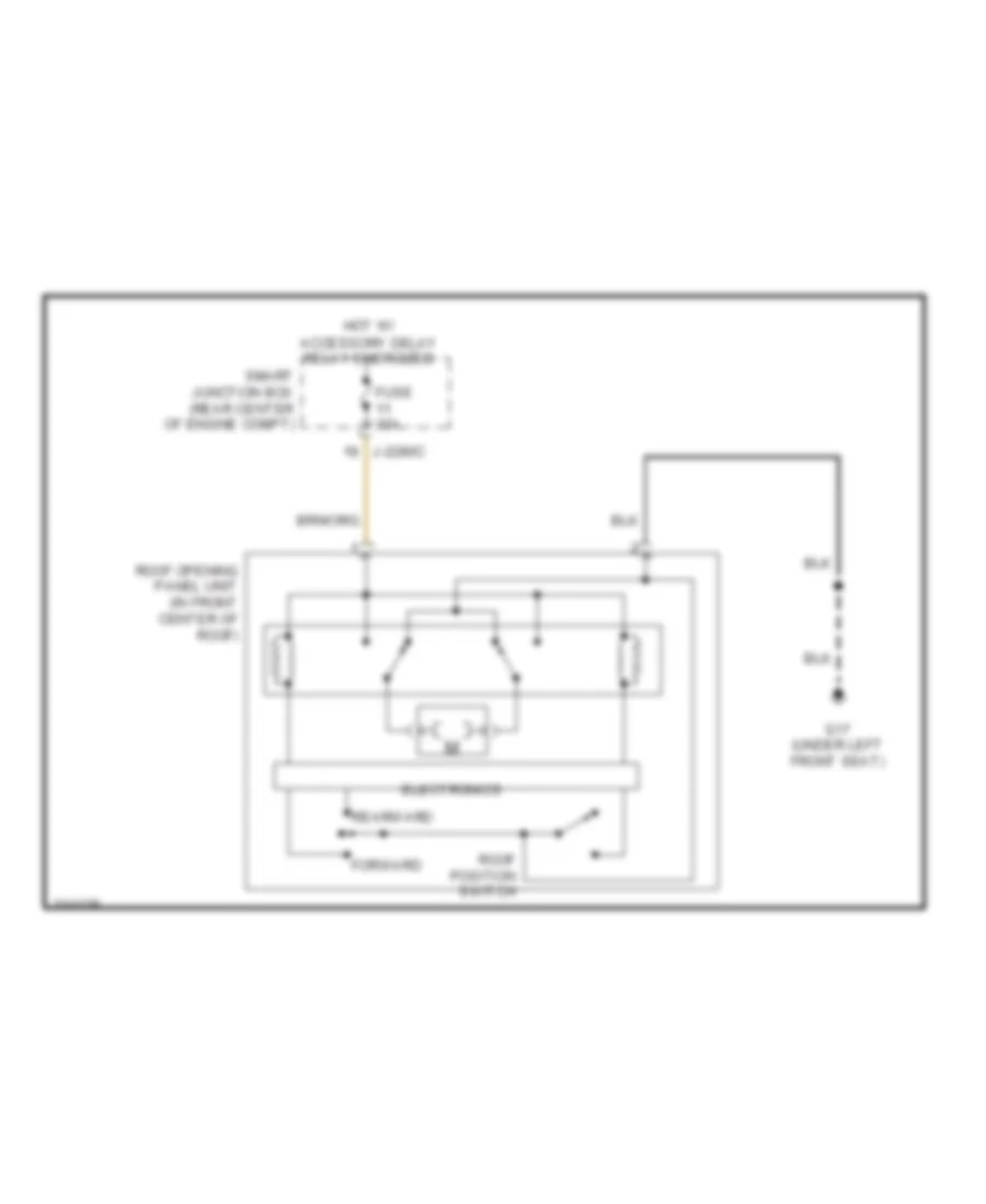
Power Top/Sunroof Wiring Diagram for Mazda Tribute s 2005
List of elements for Power Top/Sunroof Wiring Diagram for Mazda Tribute s 2005:
- Electronics
- Forward
- Fuse 15a
- G17 (under left front seat)
- Hot w/ accessory delay relay energized
- J-2280c
- Rearward
- Roof opening panel unit (in front center of roof)
- Roof position switch
- Smart junction box (rear center of engine compt)
POWER WINDOWS
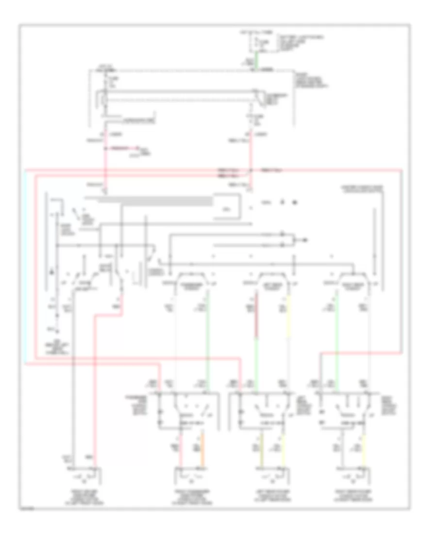
Power Windows Wiring Diagram for Mazda Tribute s 2005
List of elements for Power Windows Wiring Diagram for Mazda Tribute s 2005:
- (not used) c-312
- 40a
- Accessory delay relay
- Battery junction box (on left side of engine compt)
- Cpu
- Door lock/ unlock
- Down
- Down relay
- Driver
- Front driver side power window motor (in left front door)
- Front passenger side power window motor (in right front door)
- Fuse
- Fuse 10a
- Fuse 30a
- G20 (behind left rear wheelwell)
- Hot at all times
- J-2280b
- J-2280c
- J-2280d
- Left rear power window motor (in left rear door)
- Left rear window
- Left rear window adjust switch
- Master window door lock/unlock switch
- Microcomputer
- One touch down
- Passenger side window adjust switch
- Passenger window
- Red
- Right rear power window motor (in right rear door)
- Right rear window
- Right rear window adjust switch
- Smart junction box (rear center of engine compt)
- Window lockout
RADIO
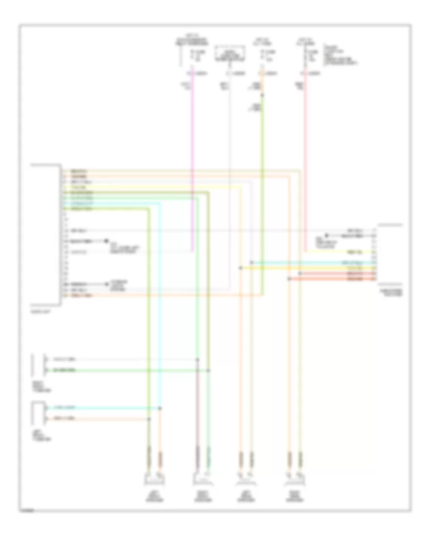
Radio Wiring Diagram for Mazda Tribute s 2005
List of elements for Radio Wiring Diagram for Mazda Tribute s 2005:
- Audio unit
- Fuse 10a
- Fuse 15a
- Fuse 5a
- G13 (at lower left side of dash)
- G23 (center of tailgate)
- Hot at all times
- Hot w/ run/accessory relay energized
- Interior lights system
- J-2280a
- J-2280c
- J-2280e
- Left front speaker
- Left front tweeter
- Left rear speaker
- Micro- computer start status
- Right front speaker
- Right front tweeter
- Right rear speaker
- Smart junction box (rear center of engine compt)
- Subwoofer amplifier
SHIFT INTERLOCK
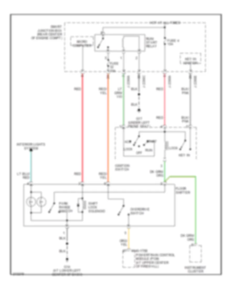
Shift Interlock Wiring Diagram for Mazda Tribute s 2005
List of elements for Shift Interlock Wiring Diagram for Mazda Tribute s 2005:
- 0140-175b
- Acc
- Floor shifter
- Fuse 10a
- Fuse 4 10a
- G14 (at lower left center of dash)
- G17 (under left front seat)
- Hot at all times
- Ignition switch
- Instrument cluster
- Interior lights system
- J-2280a
- J-2280c
- J-2280e
- Key in
- Key in ignition
- Lock
- Micro computer
- Off
- Overdrive switch
- Park range switch
- Powertrain control module (pcm) (at upper center of firewall)
- Red
- Run
- Run/ start relay
- Shift lock solenoid
- Smart junction box (rear center of engine compt)
- Start
STARTING/CHARGING
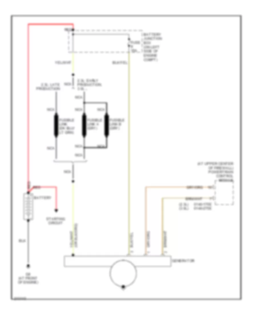
Charging Wiring Diagram for Mazda Tribute s 2005
List of elements for Charging Wiring Diagram for Mazda Tribute s 2005:
- (2.3l) (3.0l)
- (at upper center of firewall) powertrain control module
- 0140-175e 0140-275e
- 2.3l: early production, 3.0l
- 2.3l: late production
- Battery
- Battery junction box (on left side of engine compt)
- Fuse 15a
- G8 (at front of engine)
- Generator
- Nca
- Red
- Starting circuit
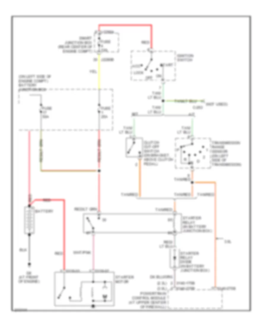
Starting Wiring Diagram for Mazda Tribute s 2005
List of elements for Starting Wiring Diagram for Mazda Tribute s 2005:
- (2.3l)
- (3.0l)
- (not used)
- (on left side of engine compt) battery junction box
- 0119-01
- 0119-02
- 0140-175b
- 0140-275b
- 3.0l
- A/t
- Acc
- Battery
- C-263
- Clutch cut-off switch (on bracket, above clutch pedal)
- Fuse 10a
- Fuse 25a
- Fuse 50a
- G8 (at front of engine)
- Ignition switch
- J2280a
- J2280b
- Lock
- M/t
- Off
- Powertrain control module (at upper center of firewall)
- Red
- Smart junction box (rear center of engine compt)
- Start
- Starter motor
- Starter relay (in battery junction box)
- Starter relay diode (in battery junction box)
- Tan/red
- Transmission range sensor (on left side of transmission)
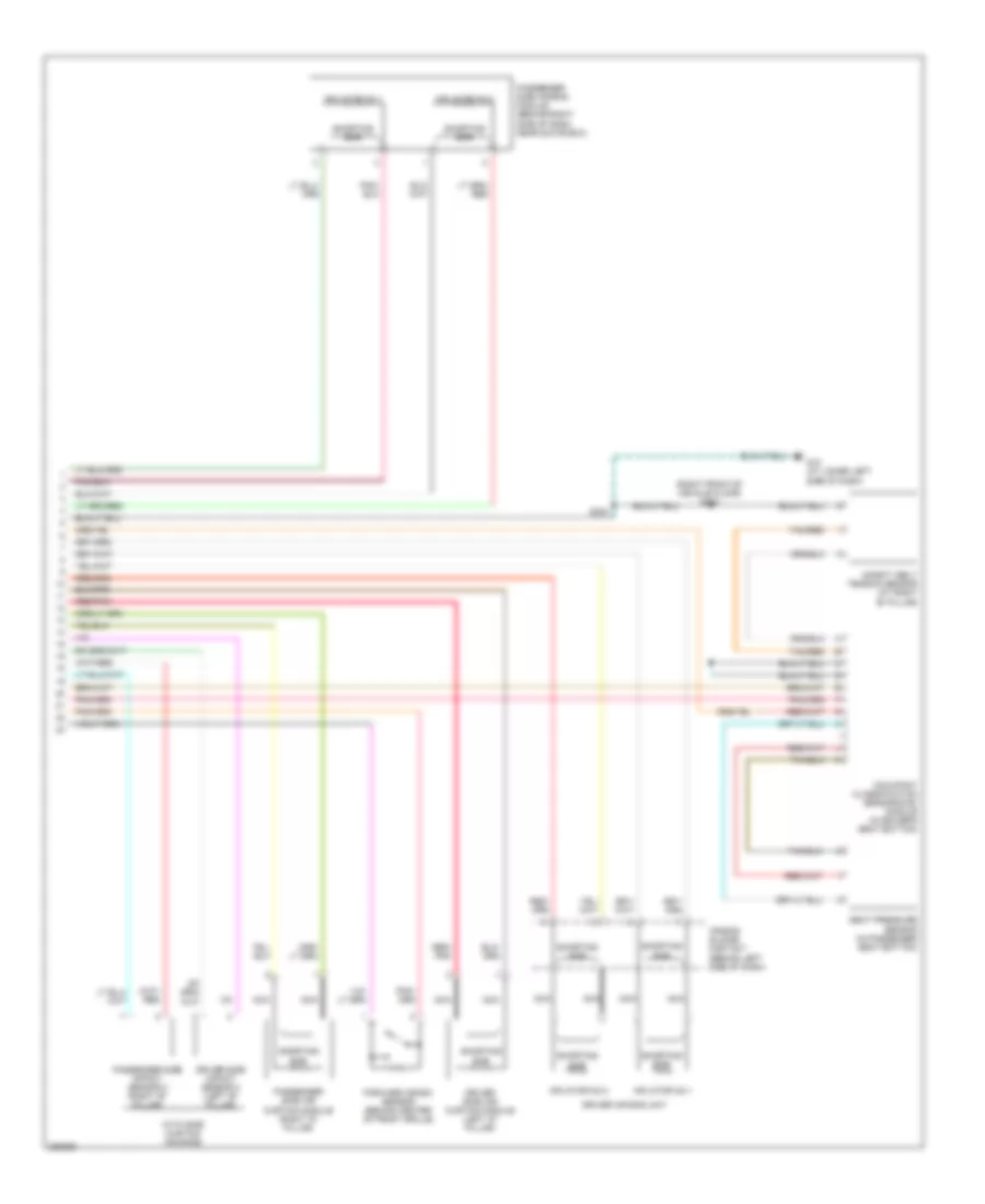
SUPPLEMENTAL RESTRAINTS
Supplemental Restraints Wiring Diagram (1 of 2) for Mazda Tribute s 2005
List of elements for Supplemental Restraints Wiring Diagram (1 of 2) for Mazda Tribute s 2005:
- Air bag deactivation warning ind
- Buckle status
- C101
- C102
- Data link connector (dlc) (on lower left side of dash)
- Driver safety belt retractor pretensioner
- Driver seat position sensor (under driver's seat bottom)
- Driver seat belt buckle sensor
- Driver side impact sensor 1 (under left front seat)
- Fuse 33 15a
- G12 (at lower left side of dash)
- Hot in run or start
- Instrument cluster
- J2280a
- Late production
- Left side air bag module (under left front seat)
- Passenger safety belt retractor pretensioner
- Passenger seat belt buckle sensor
- Passenger side impact sensor 1 (under right front seat)
- Red
- Red/pnk
- Restraints control module (under lower center of dash, on floor)
- Right side air bag module (under right front seat)
- Ril
- S204
- S300 (right front of vehicle floor)
- S327
- S329
- Shorting bar
- Smart junction box (rear center of engine compartment)
Supplemental Restraints Wiring Diagram (2 of 2) for Mazda Tribute s 2005
List of elements for Supplemental Restraints Wiring Diagram (2 of 2) for Mazda Tribute s 2005:
- (right front of vehicle floor) s300
- Air bag sliding contact (behind left side of dash)
- Driver air bag unit
- Driver side air curtain module (left "d" pillar)
- Driver side impact sensor 2 (left "b" pillar)
- Forward crash sensor (behind center of front grille)
- G12 (at lower left side of dash)
- Inflator no.1
- Inflator no.2
- Nca
- Occupant classification sensor(ocs) module (in driver's seat bottom)
- Passenger side air bag module (behind right side of dash, near glove box)
- Passenger side air curtain module (right "d" pillar)
- Passenger side impact sensor 2 (right "b" pillar)
- Red/ pnk
- Red/pnk
- S224
- Safety belt tension sensor (at right "b" pillar)
- Seat pressure sensor (in passenger seat bottom)
- Shorting bar
- Tan/red
- With side curtain air bags
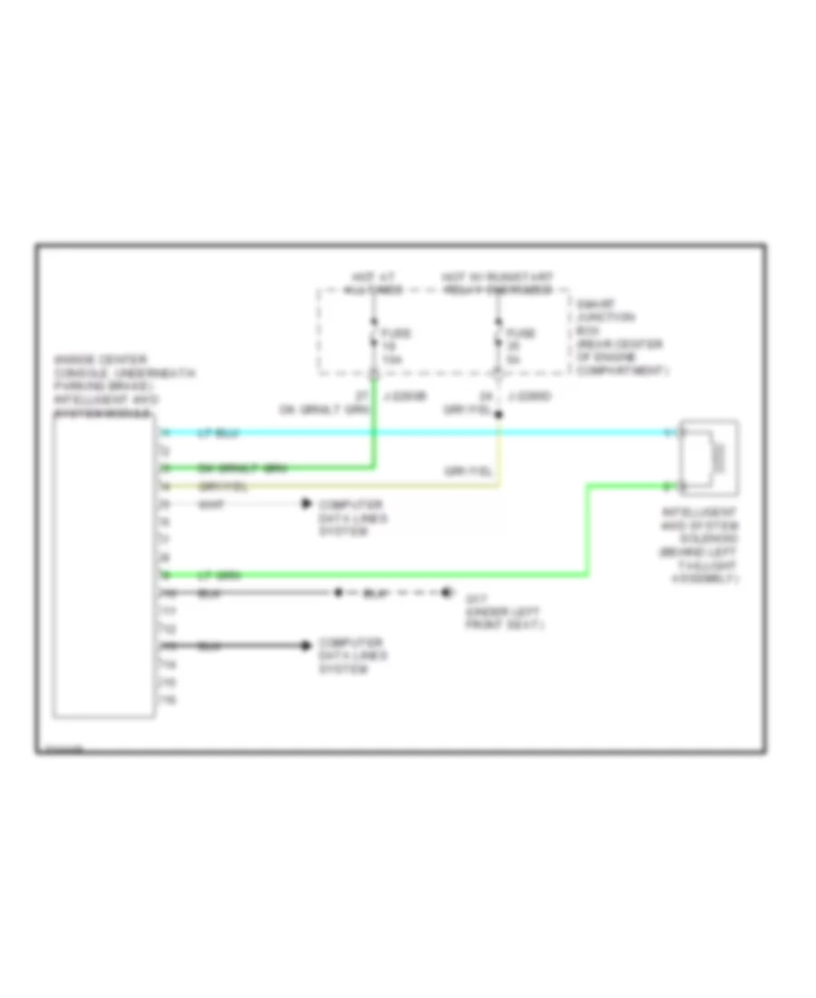
TRANSMISSION
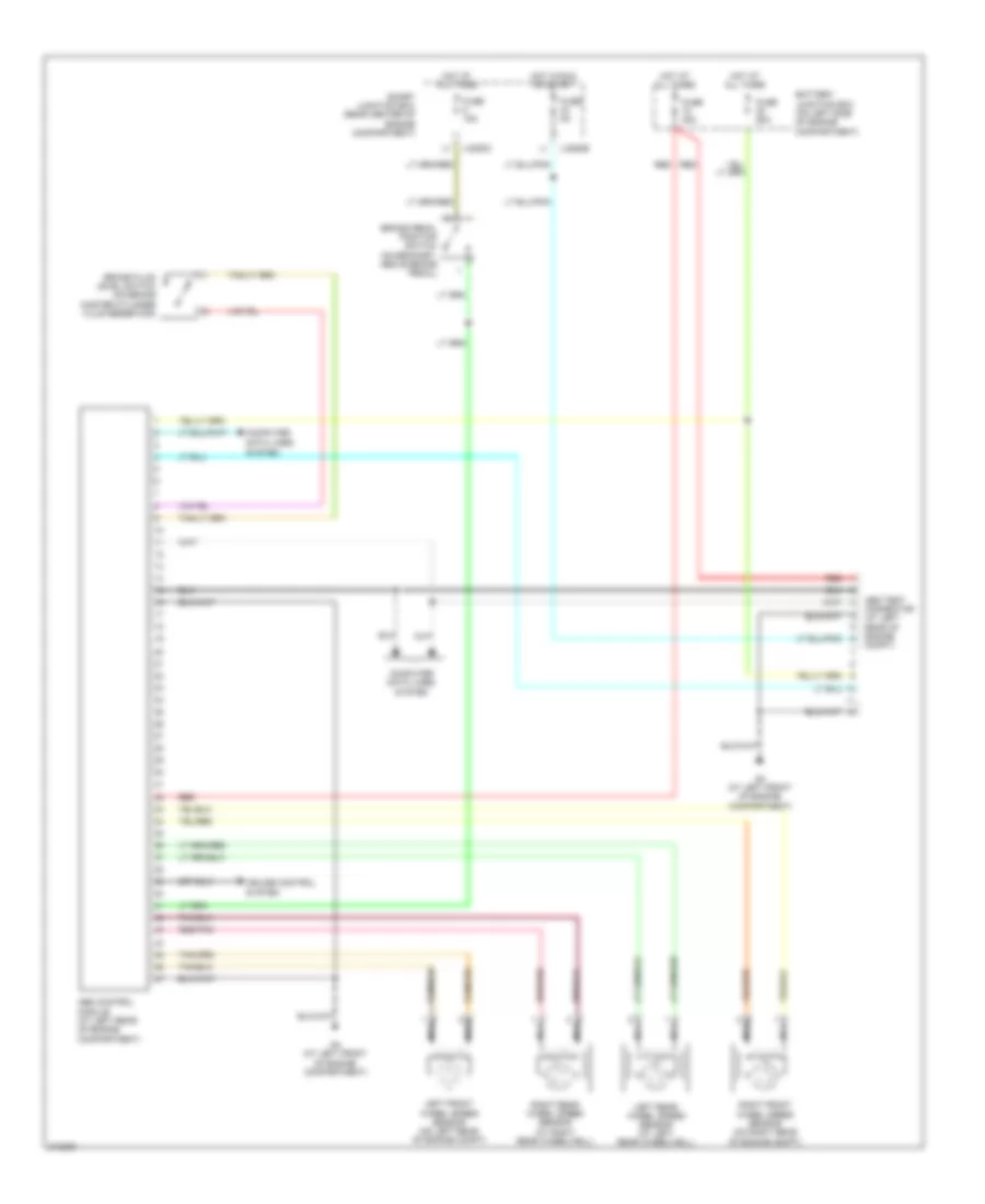
4WD Wiring Diagram for Mazda Tribute s 2005
List of elements for 4WD Wiring Diagram for Mazda Tribute s 2005:
- (inside center console, underneath parking brake) intelligent 4wd system module
- Computer data lines system
- Fuse 10a
- Fuse 5a
- G17 (under left front seat)
- Hot at all times
- Hot w/ run/start relay energized
- Intelligent 4wd system solenoid (behind left taillight assembly)
- J-2280b
- J-2280d
- Smart junction box (rear center of engine compartment)
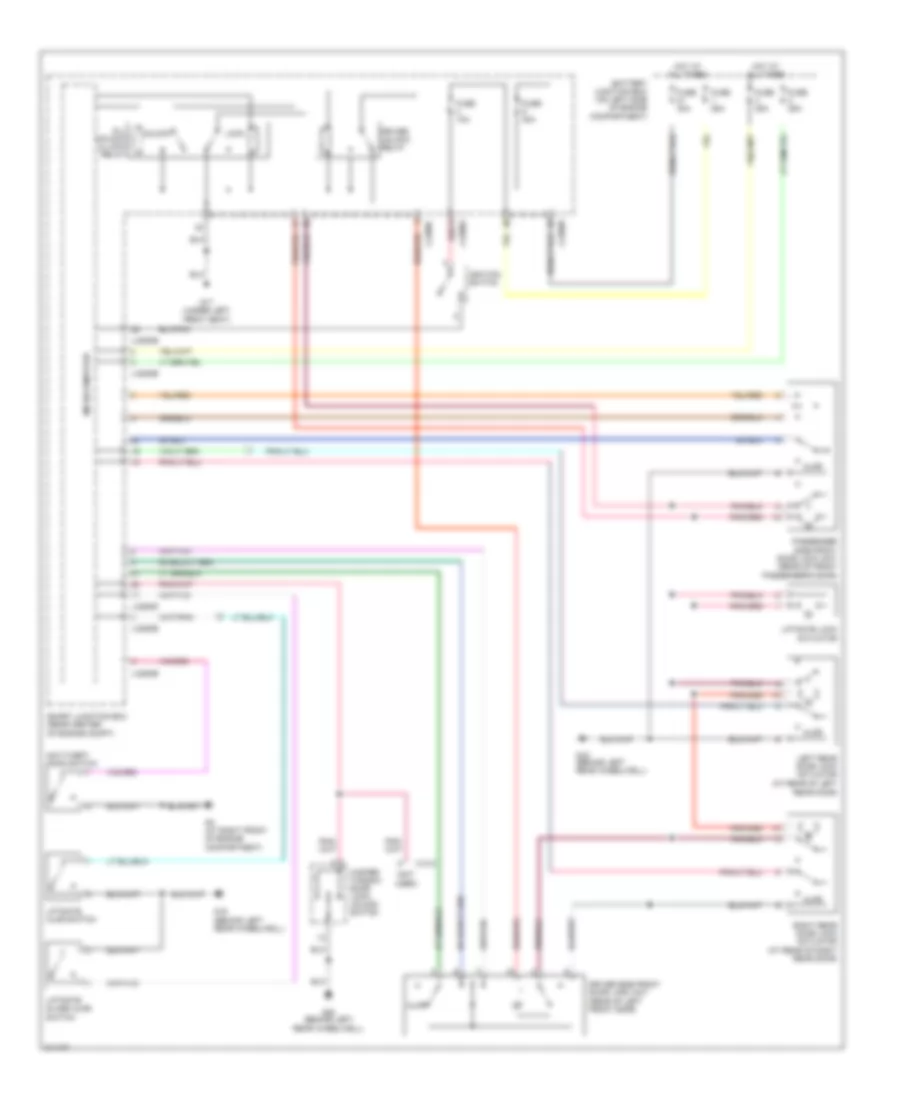
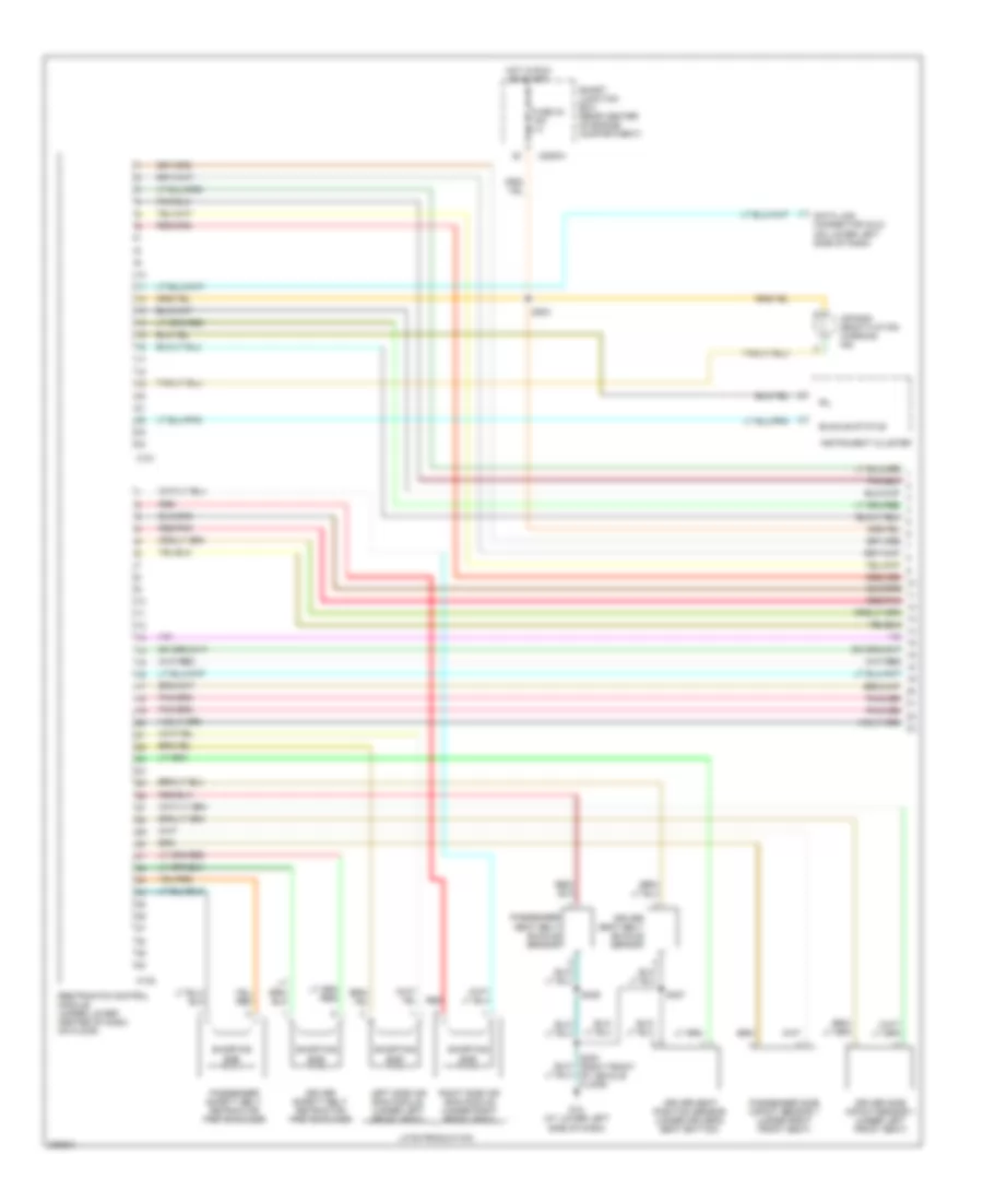
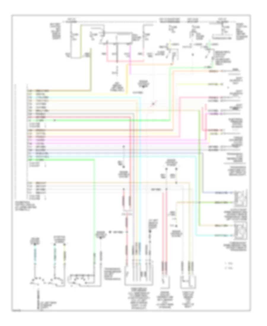
A/T Wiring Diagram for Mazda Tribute s 2005
List of elements for A/T Wiring Diagram for Mazda Tribute s 2005:
- (at left rear of engine compt) g1
- 0140-175b
- 0140-175e
- 0140-175t
- 0140-275b
- 0140-275e
- 0140-275t
- 2.3l
- 3.0l
- Battery junction box (on left side of engine compt)
- Brake pedal position switch (on bracket, above brake pedal)
- Cruise control system
- Electronic pressure control solenoid
- Engine controls system
- Engine coolant temperature (ect) sensor (3.0l) (at right rear of engine)
- Floor shifter
- Fuse 10a
- Fuse 15a
- Fuse 2a
- Fuse 30a
- Fuse 5a
- G20 (behind left rear wheelwell)
- Hot at all times
- Hot in on or start
- Hot w/ run/start relay energized
- Intake duct)
- Mass airflow (maf) sensor (2.3l: near rear of cylinder head, in air intake duct) (3.0l: at left side of engine compt, in air
- Microcomputer
- O/d sw
- Output shaft speed sensor (oss) (on right rear of transmission, near left axle flange)
- Pcm power diode
- Pcm power relay
- Powertrain control module (at upper center of firewall)
- Red
- Shift solenoid a
- Shift solenoid b
- Shift solenoid c
- Smart junction box (rear center of engine compt)
- Starting/ charging system
- Tan/red
- Throttle position sensor (tps) (on throttle body)
- Torque converter clutch solenoid
- Transmission fluid temperature sensor
- Transmission hardware unit (left front of engine compt)
- Transmission range sensor (on left side of transmission)
- Turbine shaft speed sensor (tss) (on right rear of transmission)
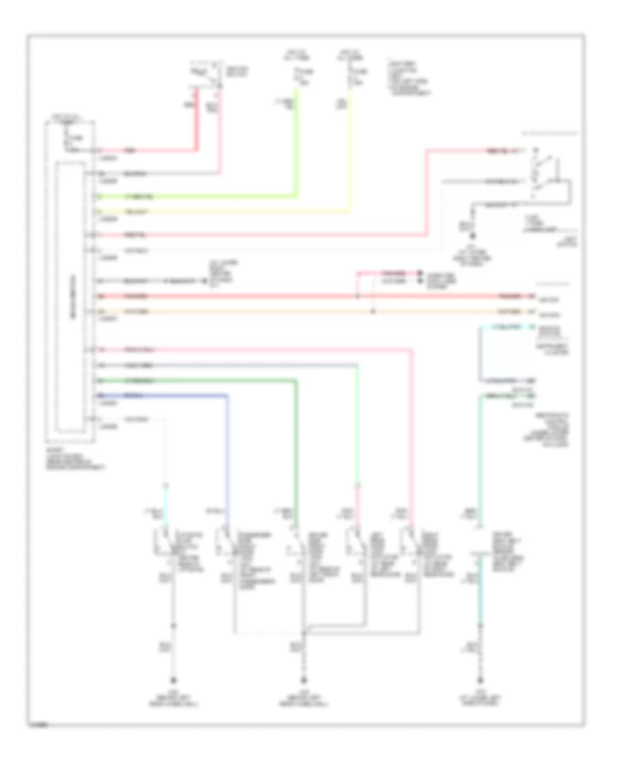
WARNING SYSTEMS
Warning Systems Wiring Diagram for Mazda Tribute s 2005
List of elements for Warning Systems Wiring Diagram for Mazda Tribute s 2005:
- (at lower right center of dash) g11
- 0 off 1 park 2 headlamp
- 0810-101
- 0810-102
- Battery junction box (on left side of engine compartment)
- Buckle status
- Computer data lines system
- Driver seat belt buckle sensor (in driver's seat belt buckle)
- Driver side front door lock unit (at rear of left front door)
- Fuse 10a
- Fuse 25a
- G11 (at lower right center of dash)
- G12 (at lower left side of dash)
- G16 (behind left rear wheelwell)
- Hot at all times
- Ignition switch
- Instrument cluster
- J-2280a
- J-2280b
- J-2280d
- J-2280e
- Key in
- Left rear door lock actuator (at rear of left rear door)
- Liftgate ajar switch (at center rear of liftgate)
- Light switch
- Microcomputer
- Ms can+
- Ms can-
- Passenger side front door lock unit (at rear of front passenger's door)
- Red
- Restraints control module (under lower center of dash, on floor)
- Right rear door lock actuator (at rear of right rear door)
- Smart junction box (rear center of engine compartment)
WIPER/WASHER
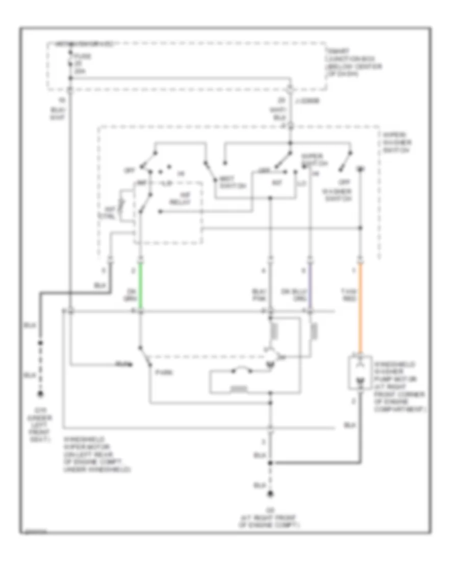
Front Wiper/Washer Wiring Diagram for Mazda Tribute s 2005
List of elements for Front Wiper/Washer Wiring Diagram for Mazda Tribute s 2005:
- Fuse 20a
- G15 (under left front seat)
- G5 (at right front of engine compt)
- Hot in on or acc
- Int
- Int ctrl
- Int relay
- J-2280b
- Mist switch
- Off
- Park
- Run
- Smart junction box (below center of dash)
- Tan/ red
- Washer switch
- Windshield washer pump motor (at right front corner of engine compartment)
- Windshield wiper motor (on left rear of engine compt, under windshield)
- Wiper switch
- Wiper/ washer switch
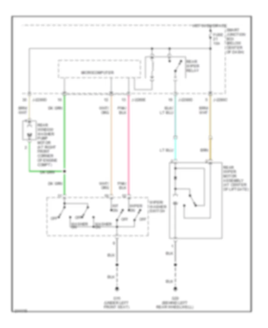
Rear Wiper/Washer Wiring Diagram for Mazda Tribute s 2005
List of elements for Rear Wiper/Washer Wiring Diagram for Mazda Tribute s 2005:
- Fuse 10a
- G15 (under left front seat)
- G20 (behind left rear wheelwell)
- Hot in on or acc
- Int on
- J-2280c
- J-2280d
- J-2280e
- Microcomputer
- Off
- Rear window washer pump motor (at right front corner of engine compt)
- Rear wiper motor assembly (at center of liftgate)
- Rear wiper relay
- Smart junction box (below center of dash)
- Washer on
- Wiper on
- Wiper/ washer switch

 Čeština
 Dansk
Dansk Deutsch
 English
 English
 Español
 Suomi
Suomi Français
 Français
 עברית
עברית Hrvatski
 Magyar
 Italiano
 日本語
日本語 한국어
한국어 Nederlands
 Polski
 Português
 Português
 Română
 Русский
 Slovenčina
 Slovenščina
 Svenska
 Türkçe
 中文 (中国)