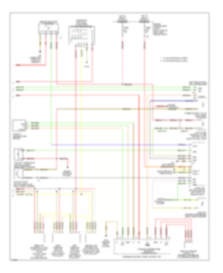
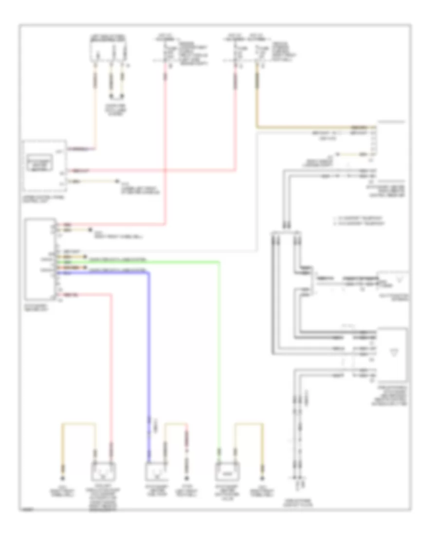
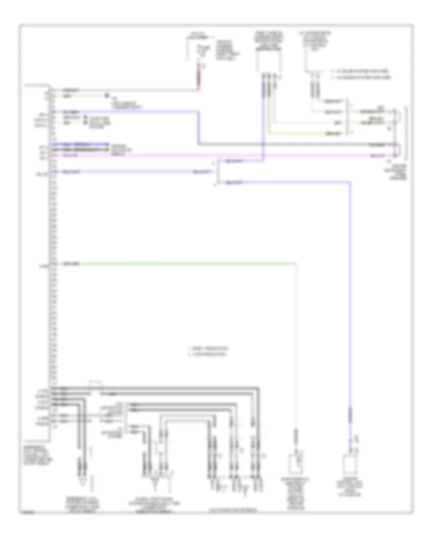
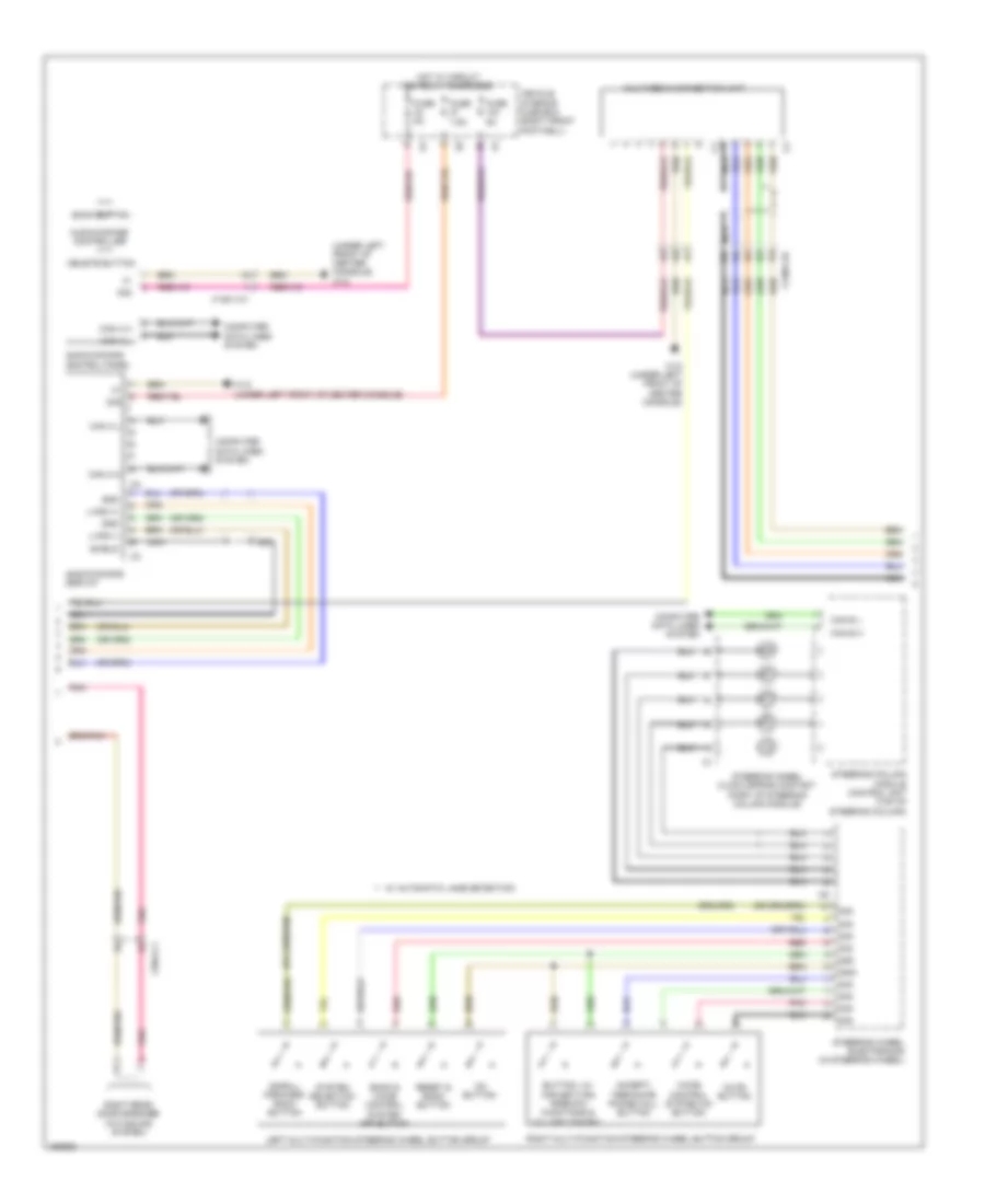
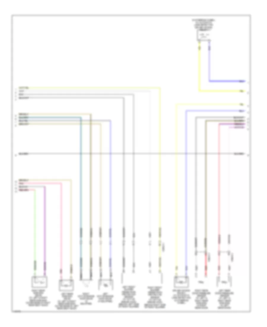
AIR CONDITIONING
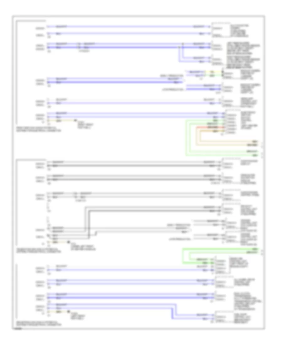
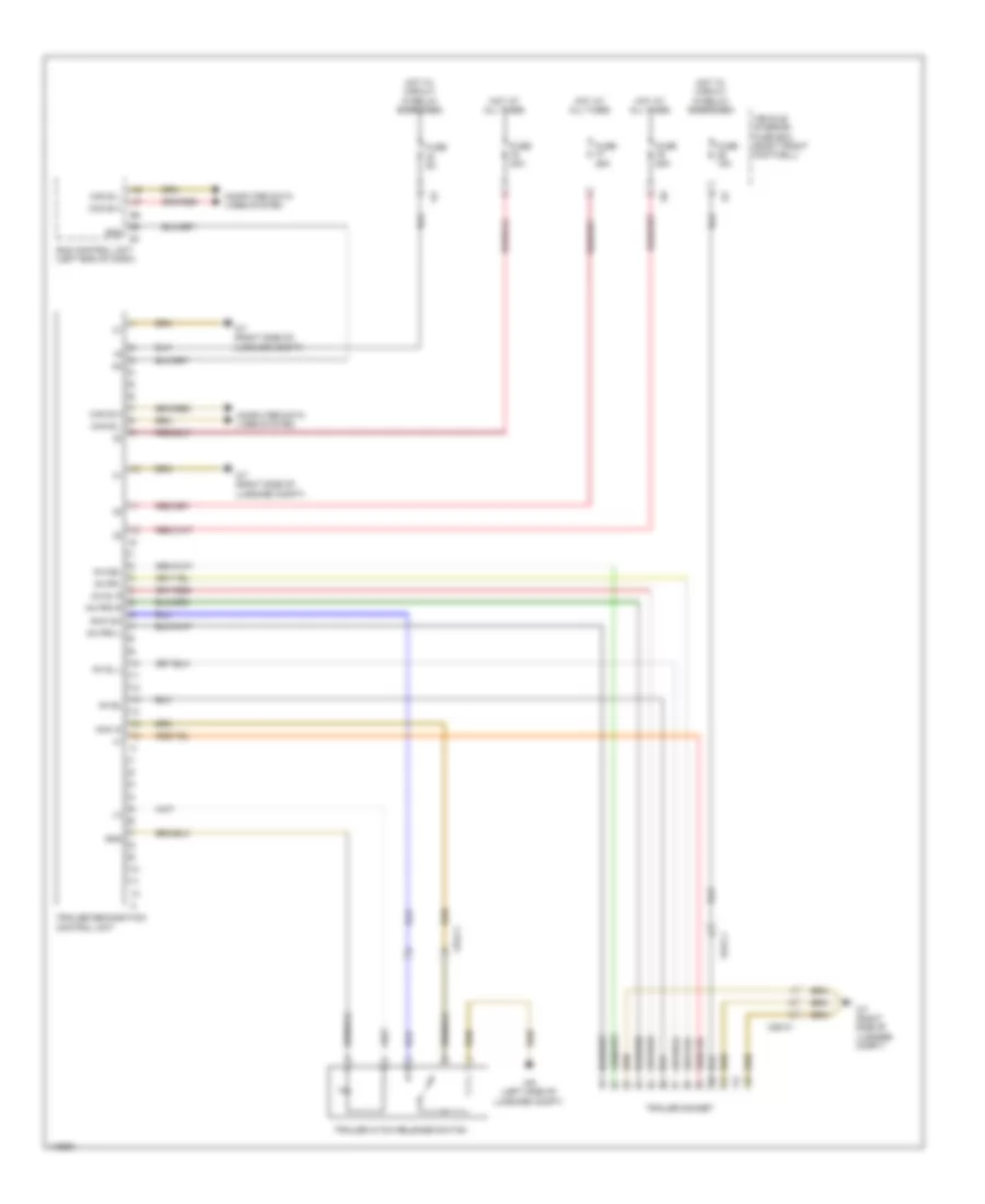
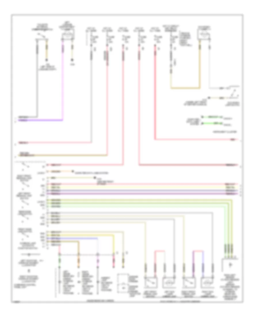
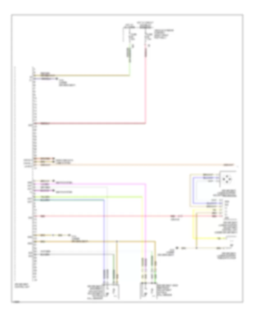
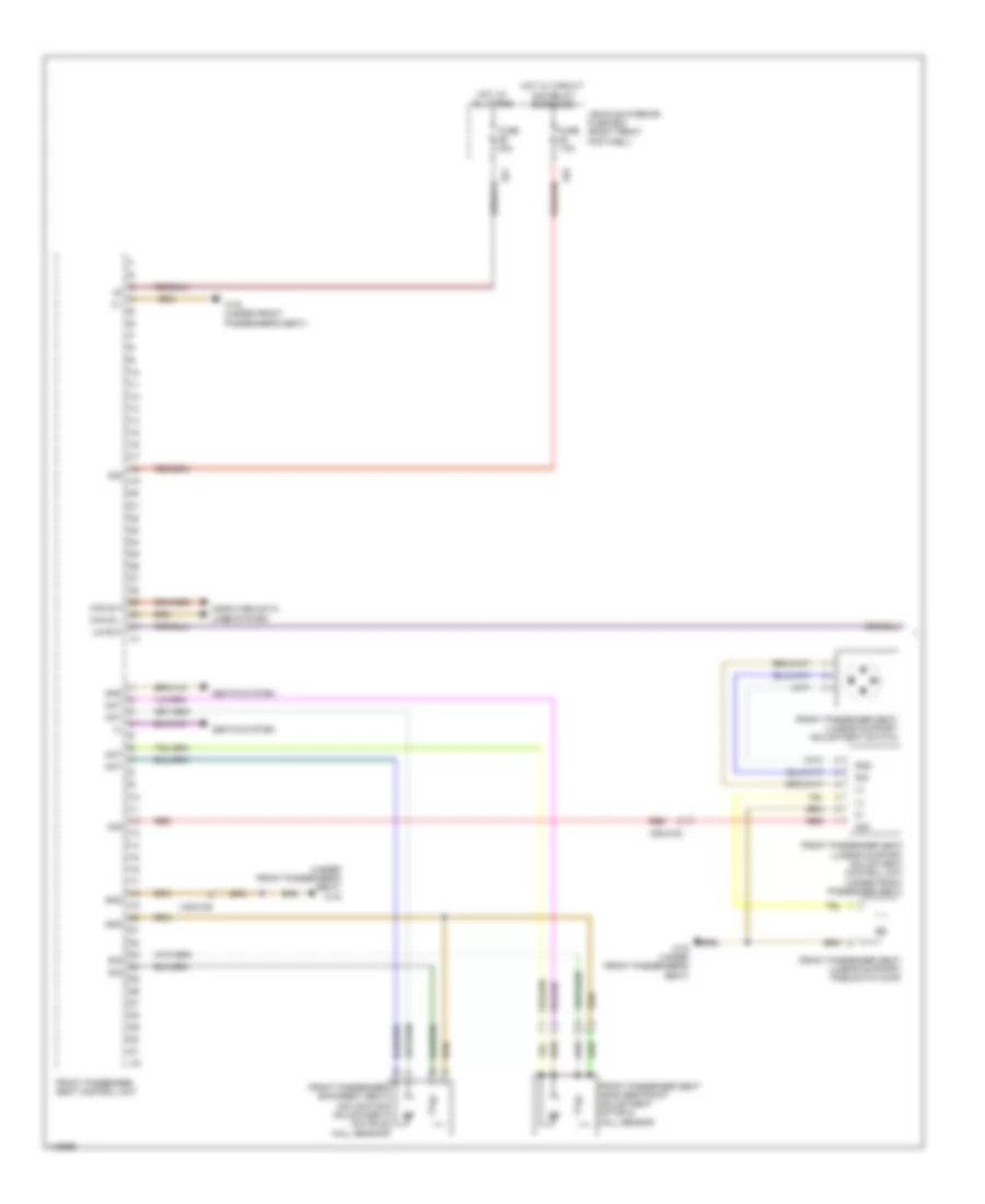
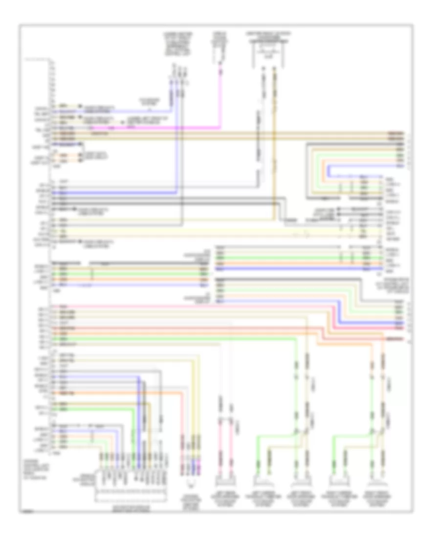
Automatic A/C Wiring Diagram (1 of 2) for Mercedes-Benz CLA250 4Matic 2014
 https://portal-diagnostov.com/license.html
Automotive Electricians Portal FZCO
Automotive Electricians Portal FZCO
https://portal-diagnostov.com/license.html
https://portal-diagnostov.com/license.html
Automotive Electricians Portal FZCO
Automotive Electricians Portal FZCO
List of elements for Automatic A/C Wiring Diagram (1 of 2) for Mercedes-Benz CLA250 4Matic 2014:
- (+)
- (behind left side of front bumper) outside temperature sensor
- (not used)
- (right rear of engine compt) coolant circulation pump
- (under left front of center console)
- 30g
- 34kd
- Ac housing
- Air quality sensor (right rear of engine compt)
- Air recir- culation mode button
- Automatic air conditioning control & operating unit
- Bf-sig
- Blower motor
- Blower regulator
- Can-b h
- Can-b l
- Central air distribution position detection microswitch (comfort) (bottom right side of hvac unit)
- Computer data lines system
- Defogger system
- Evaporator temperature sensor (lower left side of evaporator)
- F-sig
- Front electrical prefuse box (left side of engine compt)
- Fuse 10a
- Fuse 150a
- Fuse 40a
- Fuse 7.5a
- Fuse 80a
- Gnd
- Hot at all times
- Hot w/ circuit 30g relay energized
- In-b8
- Interior temperature sensor (comfort) (left center of dash)
- Lin b8
- Mk (+)
- Mot
- Nca
- Rear window heater button
- Red
- Refrigerant compressor (lower left front of engine)
- Refrigerant pressure sensor (right front of engine compt)
- Rv (+)
- Rv (-)
- S-sig
- S29
- Sig
- Sun sensor (comfort) (top center front of dash)
- Vehicle interior fuse box (right front footwell)
- W/ magnetic clutch
- W/o magnetic clutch
- W12
- W15/1 (right front footwell)
- W3/1 (right front wheelwell)
- X25/14-c1
- X26-c1
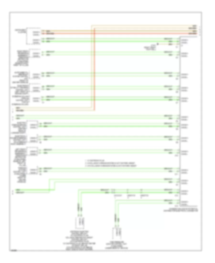
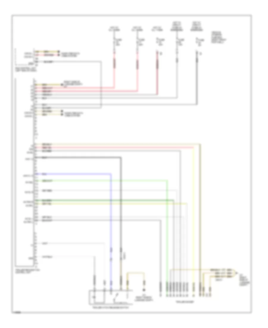
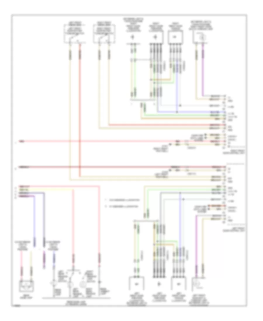
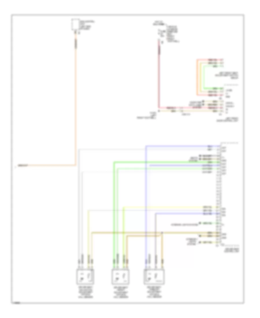
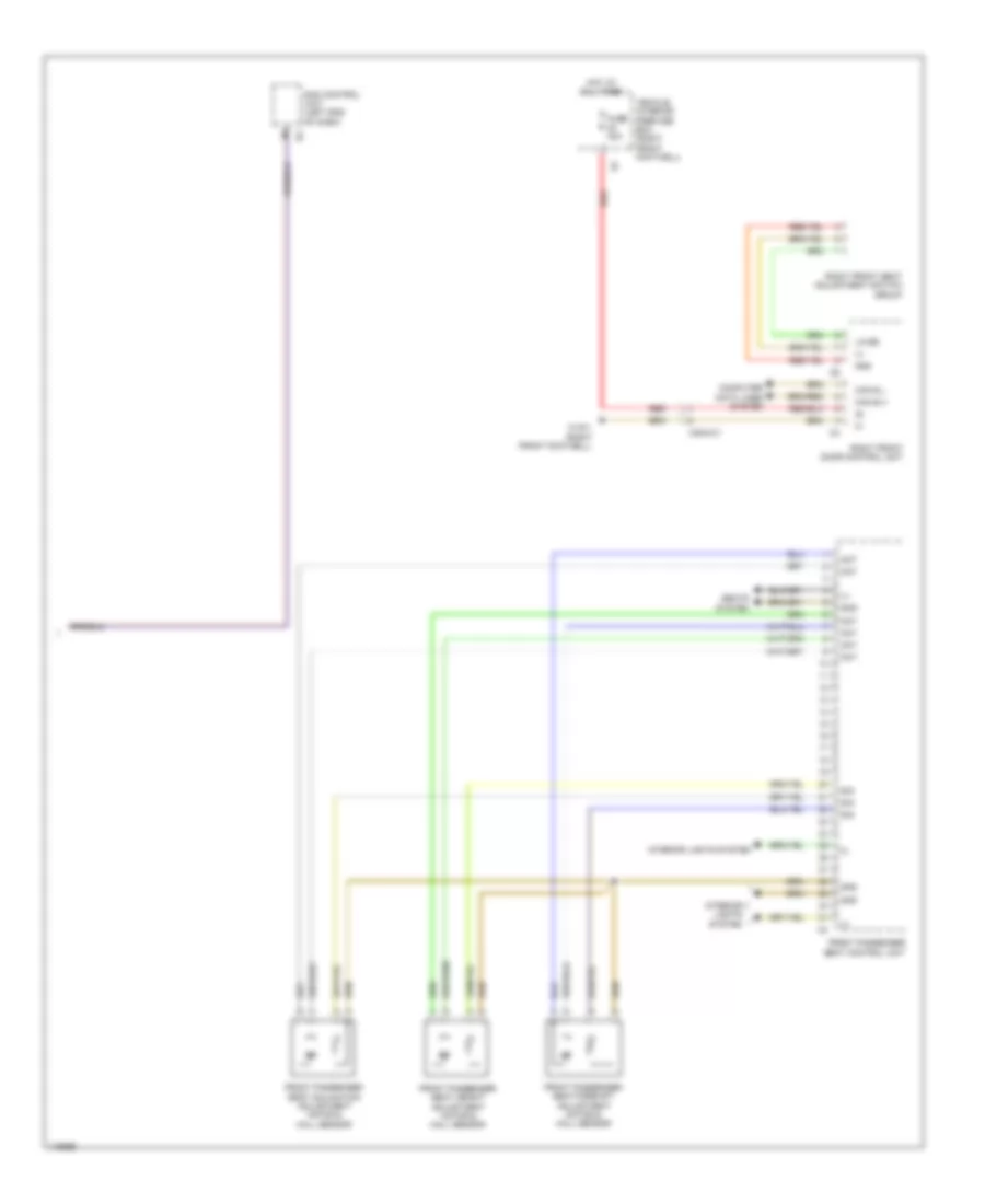
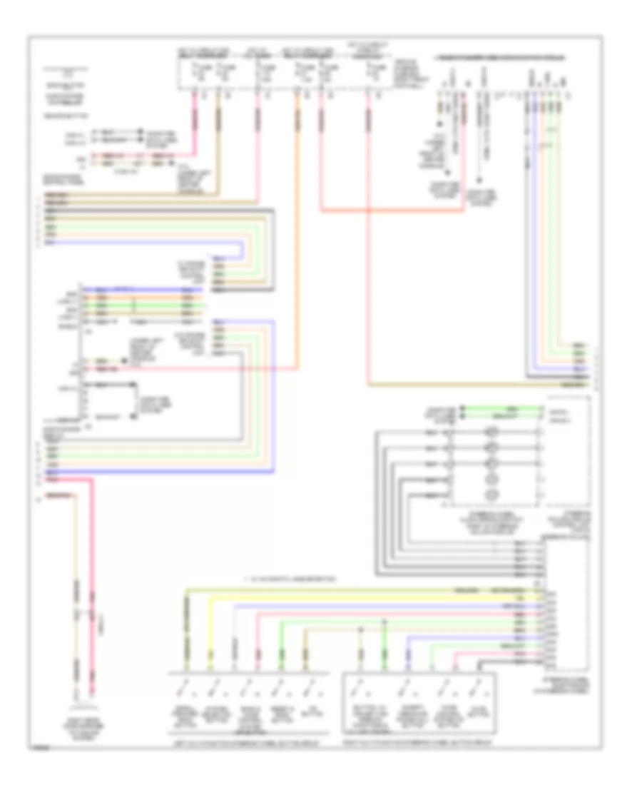
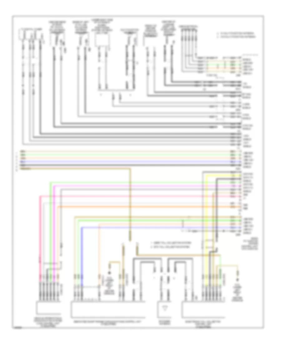
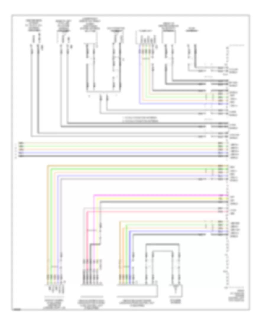
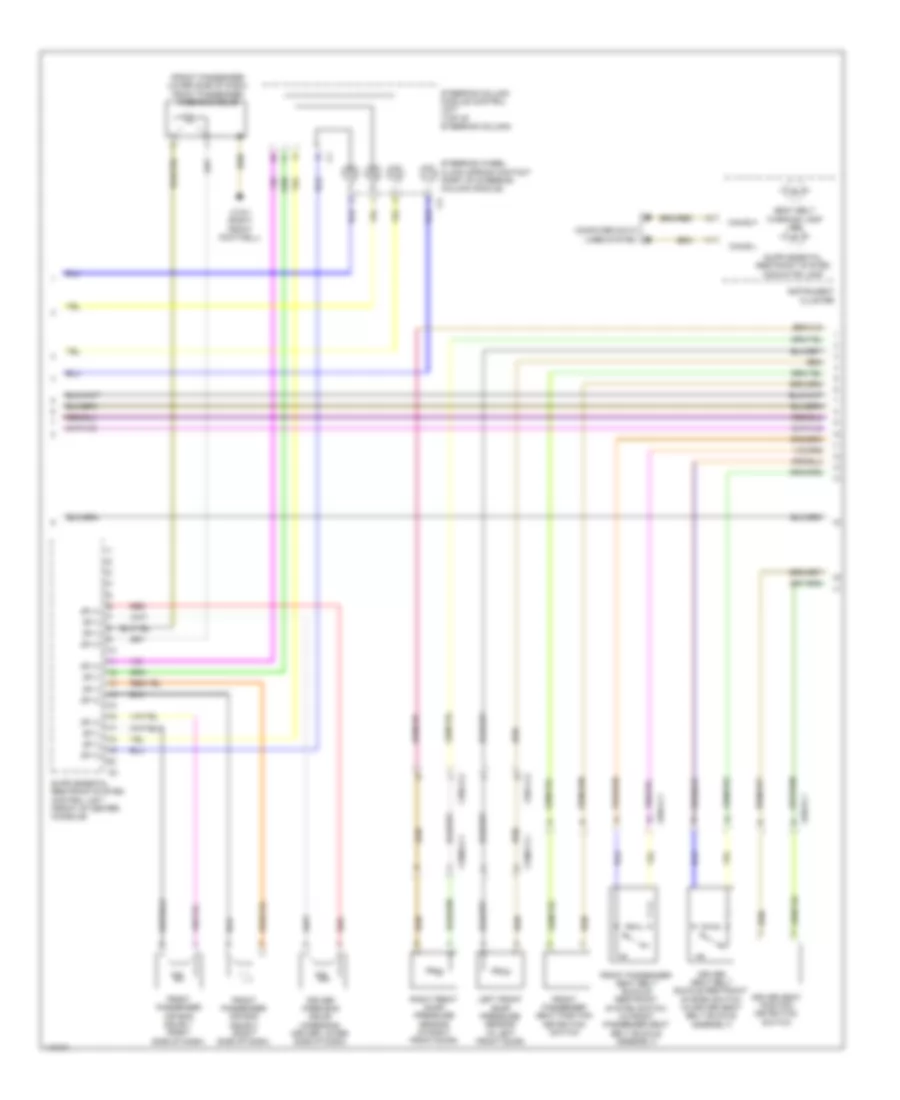
Automatic A/C Wiring Diagram (2 of 2) for Mercedes-Benz CLA250 4Matic 2014
List of elements for Automatic A/C Wiring Diagram (2 of 2) for Mercedes-Benz CLA250 4Matic 2014:
- (+)
- (behind radiator) fan motor
- (center of hvac unit) (if equipped) ptc heater booster
- (left end of dash) sam control unit
- Activated charcoal filter shutoff valve (right of fuel tank)
- Can-i h
- Can-i l
- Central air distribution actuator motor (upper right side of hvac unit)
- Computer data lines system
- Coolant pump switchover valve (right side of engine)
- Coolant temperature sensor (right side of engine)
- Coolant thermostat heating element (right side of engine)
- Engine compartment fuse & relay module (left side engine compt)
- Engine controls system
- Fresh air/ air recirculation flap actuator motor (top left side of hvac blower housing)
- Fuse 15a
- Fuse 5a
- Gnd
- Hot w/ circuit 30g relay energized
- Hot w/ circuit 87m relay energized
- Humidity/ temperature sensor
- Interior temperature sensor w/ integrated fan
- Left blending air flap actuator (comfort) (left side of hvac unit)
- Lin b13
- Me-sfi (me) control module (left front of engine compt)
- Overhead control panel control unit
- Purge control valve (right rear of engine)
- Pwm
- Red
- Right blending air flap actuator (right side of hvac unit)
- Sig
- Uh1
- Vehicle interior humidity & temperature sensor (in overhead console)
- W/ fan motor 300w & 400w
- W/ fan motor 600w & 850w
- W11 (left rear of engine compt)
- W15/7
- W78 (center front of roof)
- W9 (under left headlight assembly)
- X25/13-c2
- X36/2-c1
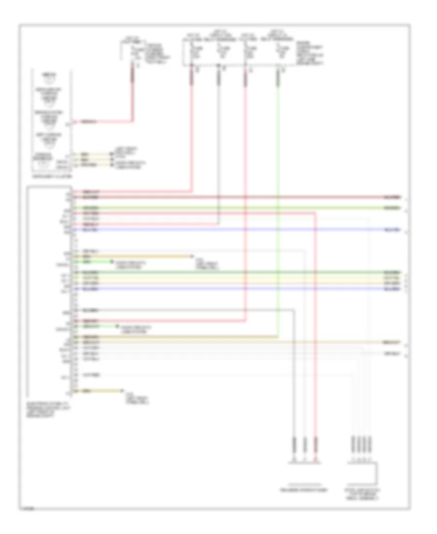
ANTI-LOCK BRAKES
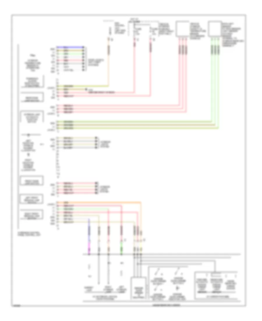
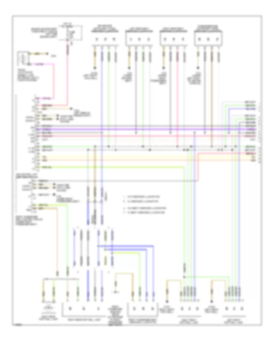
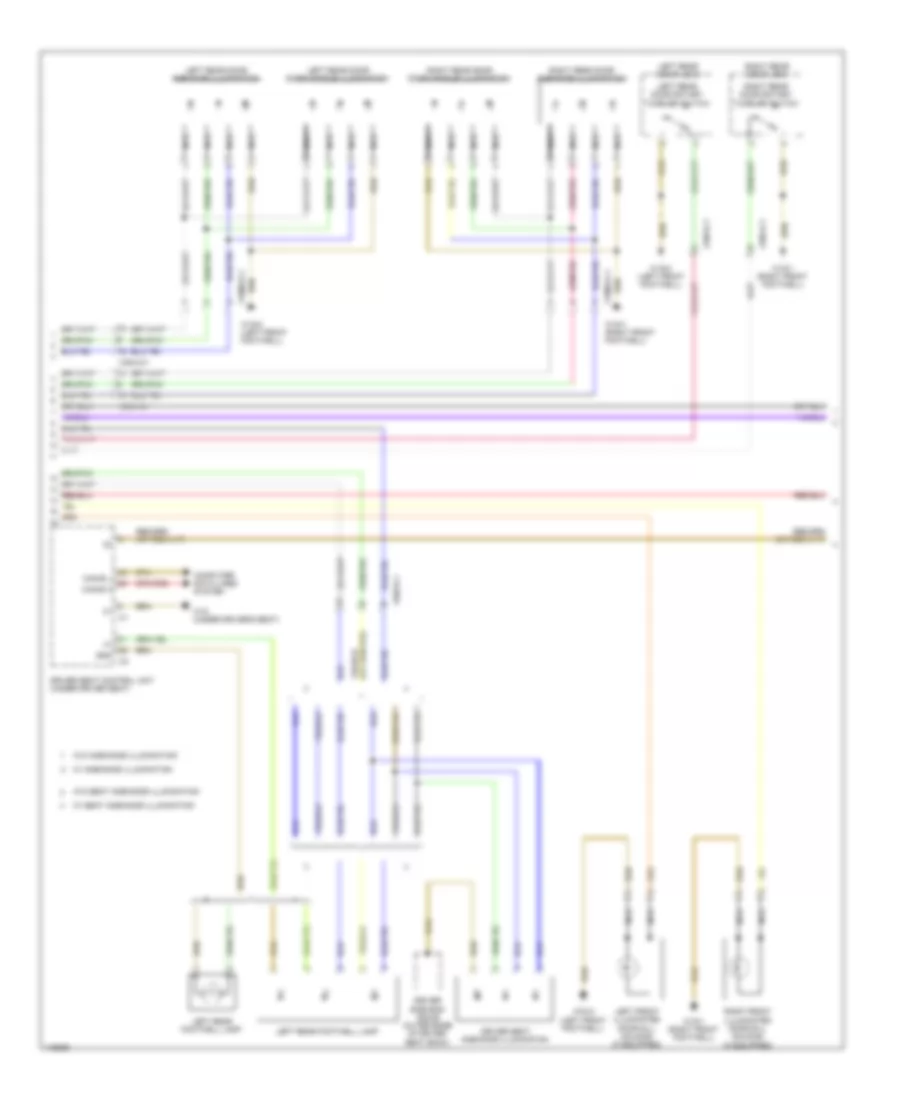
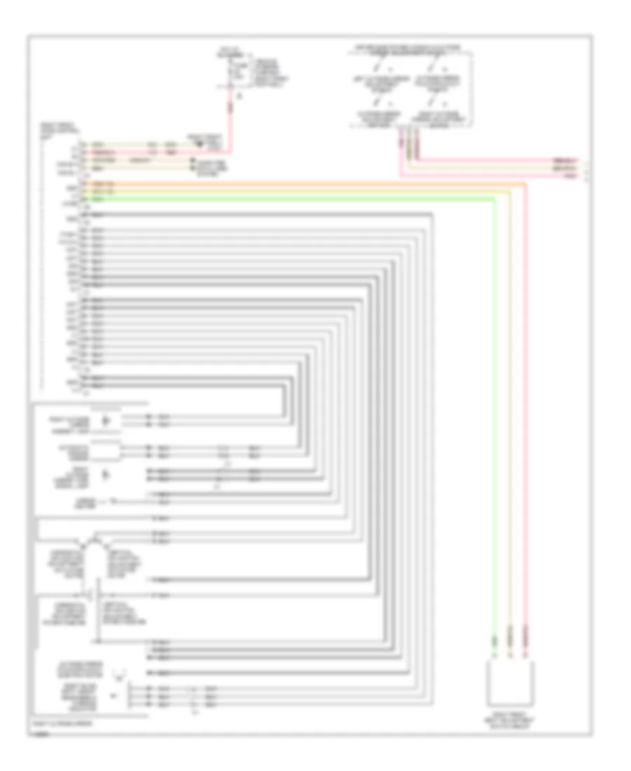
Anti-lock Brakes Wiring Diagram (1 of 2) for Mercedes-Benz CLA250 4Matic 2014
List of elements for Anti-lock Brakes Wiring Diagram (1 of 2) for Mercedes-Benz CLA250 4Matic 2014:
- (left front footwell) w15/2
- 12v +
- 30g
- 5v +
- Abs ind
- Bls h
- Bls l
- Brake system warning lamp ind
- Can e h
- Can e l
- Computer data lines system
- Electronic stability program control unit (left front of engine compt)
- Engine compartment fuse & relay module (left side engine compt)
- Esp warning lamp ind
- Espa/asr off warning lamp ind
- Fehlende informationen
- Fuse 10a
- Fuse 25a
- Fuse 40a
- Fuse 5a
- Gnd
- Hot at all times
- Hot w/ circuit 15 relay energized
- Hot w/ circuit 30g relay energized
- Instrument cluster
- Parking brake ind
- S12
- Sig
- Stop lamp switch (top of brake pedal assembly)
- Vehicle interior fuse box (right front footwell)
- W70 (left front wheelwell)
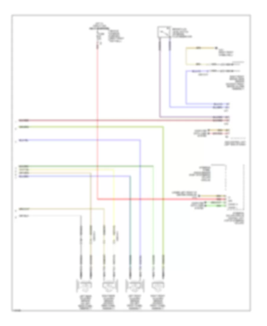
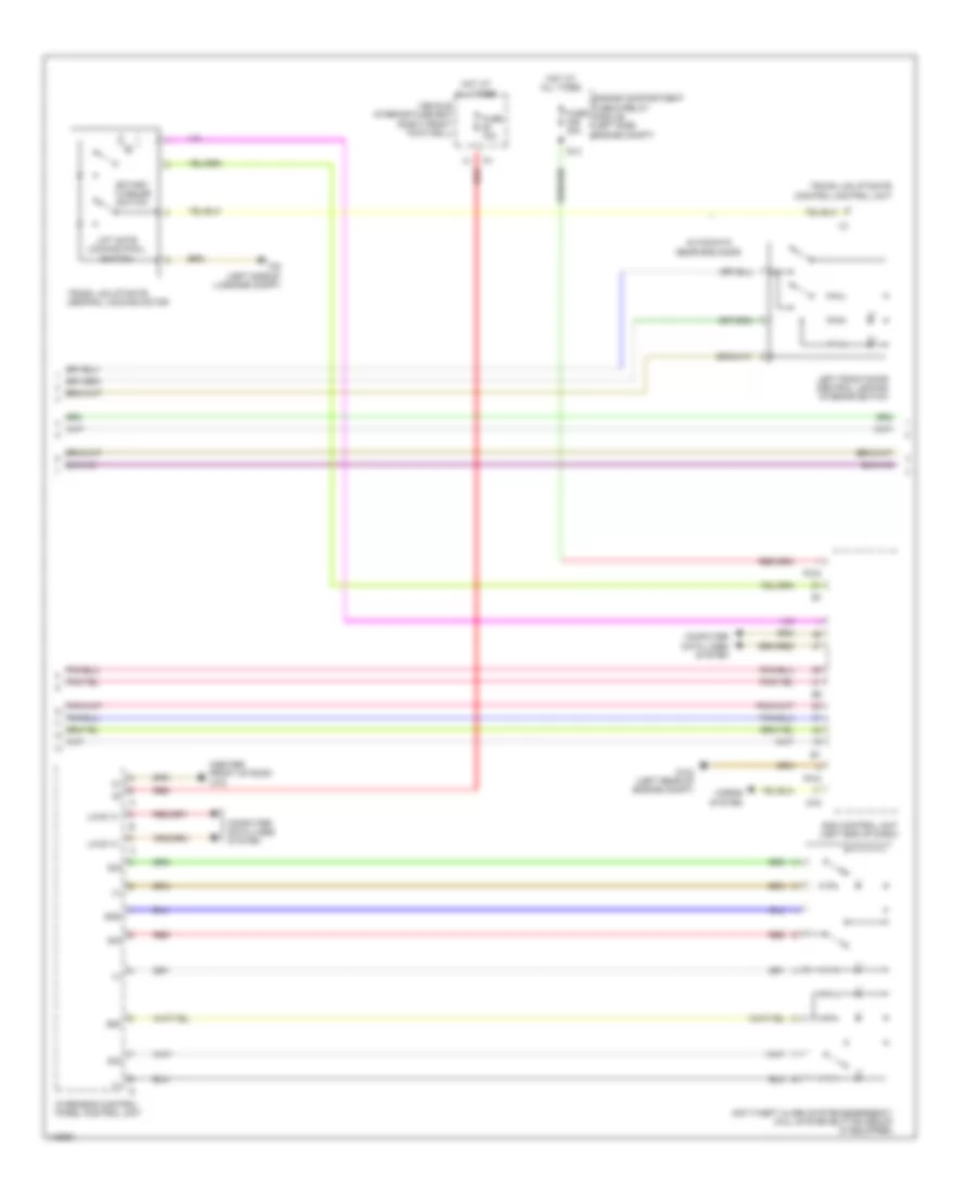
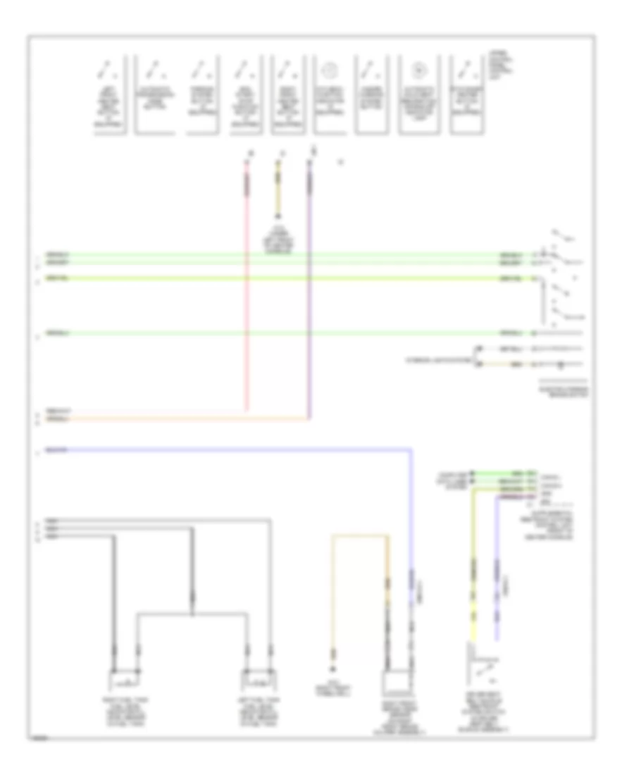
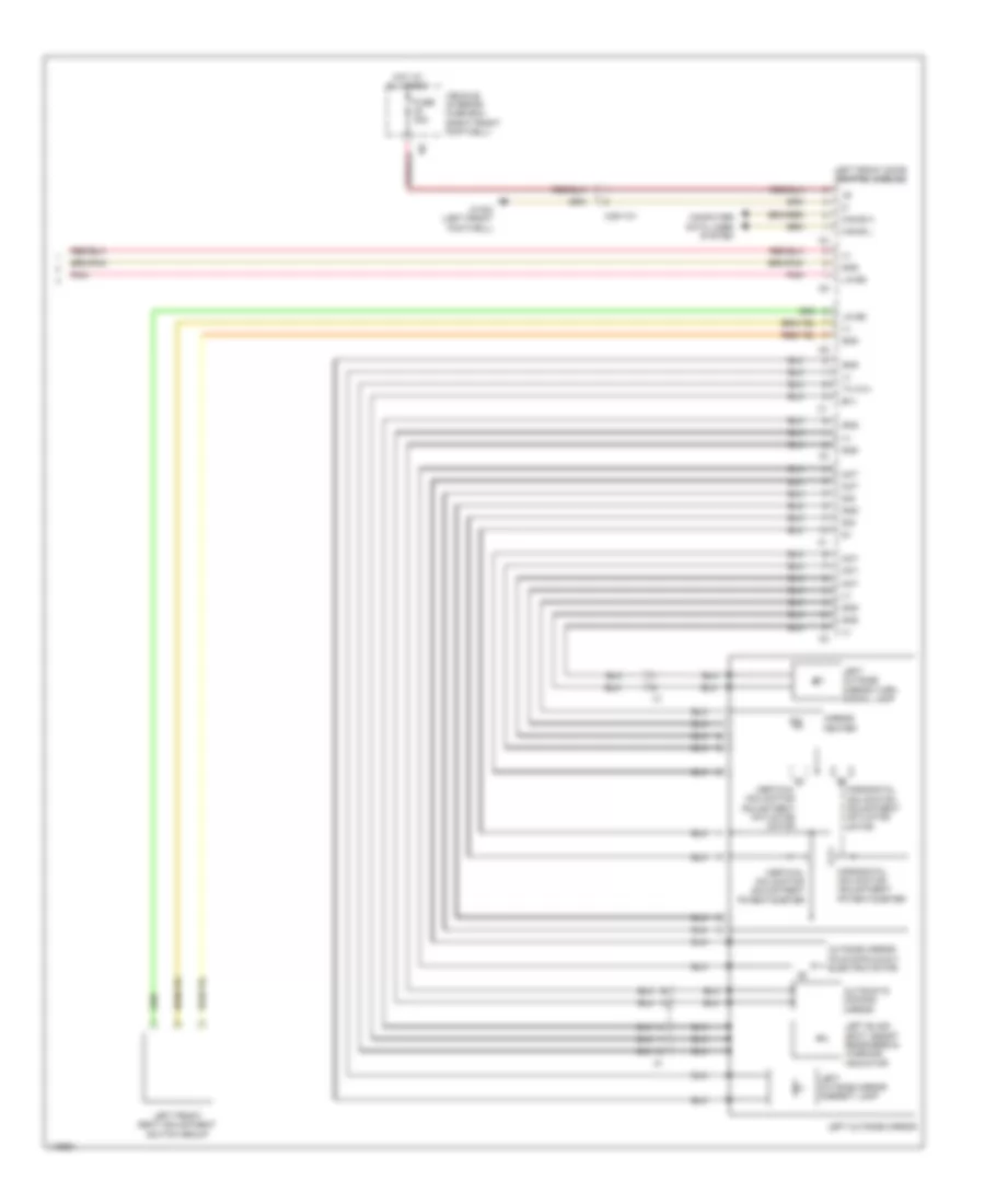
Anti-lock Brakes Wiring Diagram (2 of 2) for Mercedes-Benz CLA250 4Matic 2014
List of elements for Anti-lock Brakes Wiring Diagram (2 of 2) for Mercedes-Benz CLA250 4Matic 2014:
- (under left front of center console) w12
- 30g
- Brake fluid level switch (on brake fluid reservoir)
- Can e1 h
- Can e1 l
- Computer data lines system
- Fuse 5a
- Hot w/ circuit 30g relay energized
- Left front axle rpm sensor (on left front wheel assembly)
- Left rear axle rpm sensor (on left rear wheel assembly)
- Nca
- Red
- Right front axle rpm sensor (on right front wheel assembly)
- Right front brake wear sensor (on right front brake caliper assembly)
- Right rear axle rpm sensor (on right rear wheel assembly)
- Sam control unit (left end of dash)
- Steering column module control unit (top of steering column)
- Steering wheel angle sensor (part of steering column module)
- Uh1
- Uh2
- Vehicle interior fuse box (right front footwell)
- W3/1 (right front wheelwell)
- X25/13-c1
- X25/14-c1
- X88/12-c1
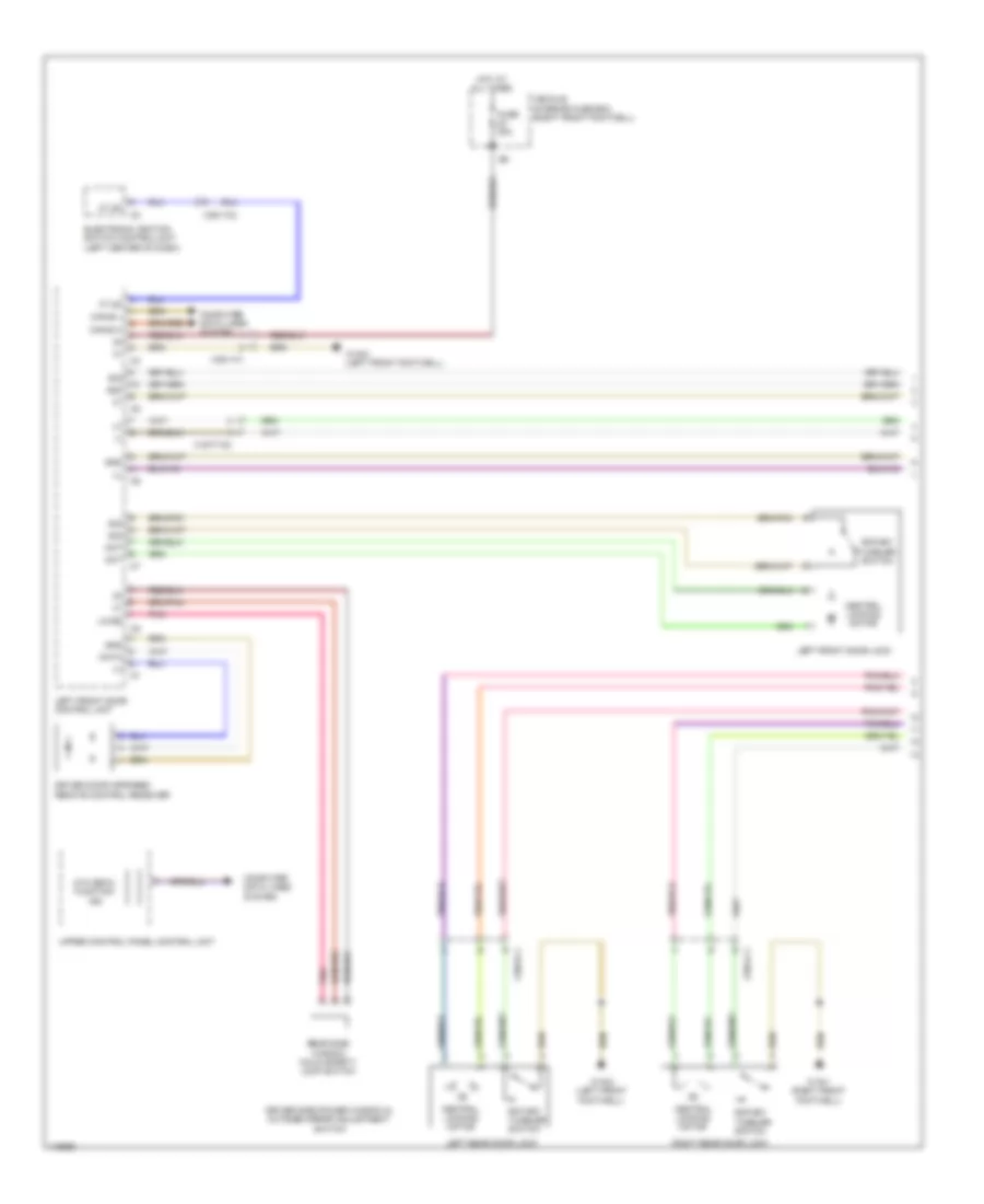
ANTI-THEFT
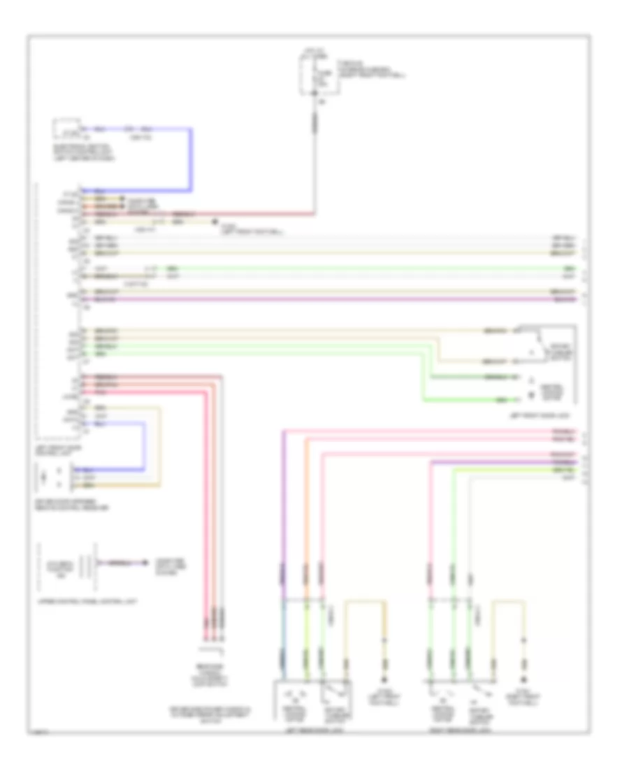
Anti-theft Wiring Diagram (1 of 3) for Mercedes-Benz CLA250 4Matic 2014
List of elements for Anti-theft Wiring Diagram (1 of 3) for Mercedes-Benz CLA250 4Matic 2014:
- (+)
- (-)
- 58d
- Ata (edw) function ind
- Can-b h
- Can-b l
- Central locking motor
- Computer data lines system
- Data
- Driver door infrared remote control receiver
- Driver side power window & outside mirror adjustment switch
- Electronic ignition switch control/unit (left center of dash)
- Ft df
- Fuse 30a
- Gnd
- Hot at all times
- Left front door control unit
- Left front door lock
- Left rear door lock
- Lin b5
- Mot
- Pnk
- Rear side window child safety lock switch
- Right rear door lock
- Rotary tumbler switch
- Sig
- Upper control panel control unit
- Vehicle interior fuse box (right front footwell)
- W15/1 (right front footwell)
- W15/2 (left front footwell)
- X157/7-c2
- X35/1-c1
- X35/1-c2
- X35/3-c1
- X35/4-c1
Anti-theft Wiring Diagram (2 of 3) for Mercedes-Benz CLA250 4Matic 2014
List of elements for Anti-theft Wiring Diagram (2 of 3) for Mercedes-Benz CLA250 4Matic 2014:
- (+)
- (center front of roof) w78
- 58d
- Anti-theft alarm system/emergency call system button group (if equipped)
- Automatic rear end door
- Computer data lines system
- Engine compartment fuse & relay module (left side engine compt)
- Fuse 10a
- Fuse 40a
- Gnd
- Horns system
- Hot at all times
- Left front door central locking interior switch
- Lift gate locking pawl switch
- Lin b 13
- Overhead control panel control unit
- Pw2
- Red
- Rotary tumbler switch
- S13
- Sam control unit (left end of dash)
- Sig
- Trunk lid/liftgate central locking motor
- Trunk lid/liftgate control control unit
- Uh2
- Vehicle interior fuse box (right front footwell)
- W3/2 (left rear of engine compt)
- W6 (left side of luggage compt)
Anti-theft Wiring Diagram (3 of 3) for Mercedes-Benz CLA250 4Matic 2014
List of elements for Anti-theft Wiring Diagram (3 of 3) for Mercedes-Benz CLA250 4Matic 2014:
- (+)
- (-)
- (under left front of center console) w12
- Ata (edw)/towing sensor/interior motion sensor control unit (in overhead control panel)
- Can b h
- Can b l
- Can-b h
- Can-b l
- Can-c h
- Can-c l
- Can-e h
- Can-e l
- Central locking motor
- Computer data
- Computer data lines system
- Dual clutch fully integrated transmission control controller unit (in transmission)
- Electronic ignition switch control unit (left center of dash)
- Fuse 10a
- Fuse 30a
- Fuse 5a
- Gnd
- Hot at all times
- Instrument cluster
- Left front door exit & warning lamp (w/ exterior lights package)
- Left front door handle illumination (w/ exterior lights package)
- Lines system
- Rear window glass breakage sensor (w/ interior protection)
- Red
- Right front door central locking interior switch
- Right front door control unit
- Right front door exit & warning lamp (w/ exterior lights package)
- Right front door handle illumination (w/ exterior lights package)
- Right front door lock
- Rotary tumbler switch
- Sig
- Vehicle interior fuse box (right front footwell)
- W15/1 (right front footwell)
- W78 (center front of roof)
- W8/4
- X157/6-c2
- X35/2-c1
- Zv-mot +
BODY CONTROL MODULES
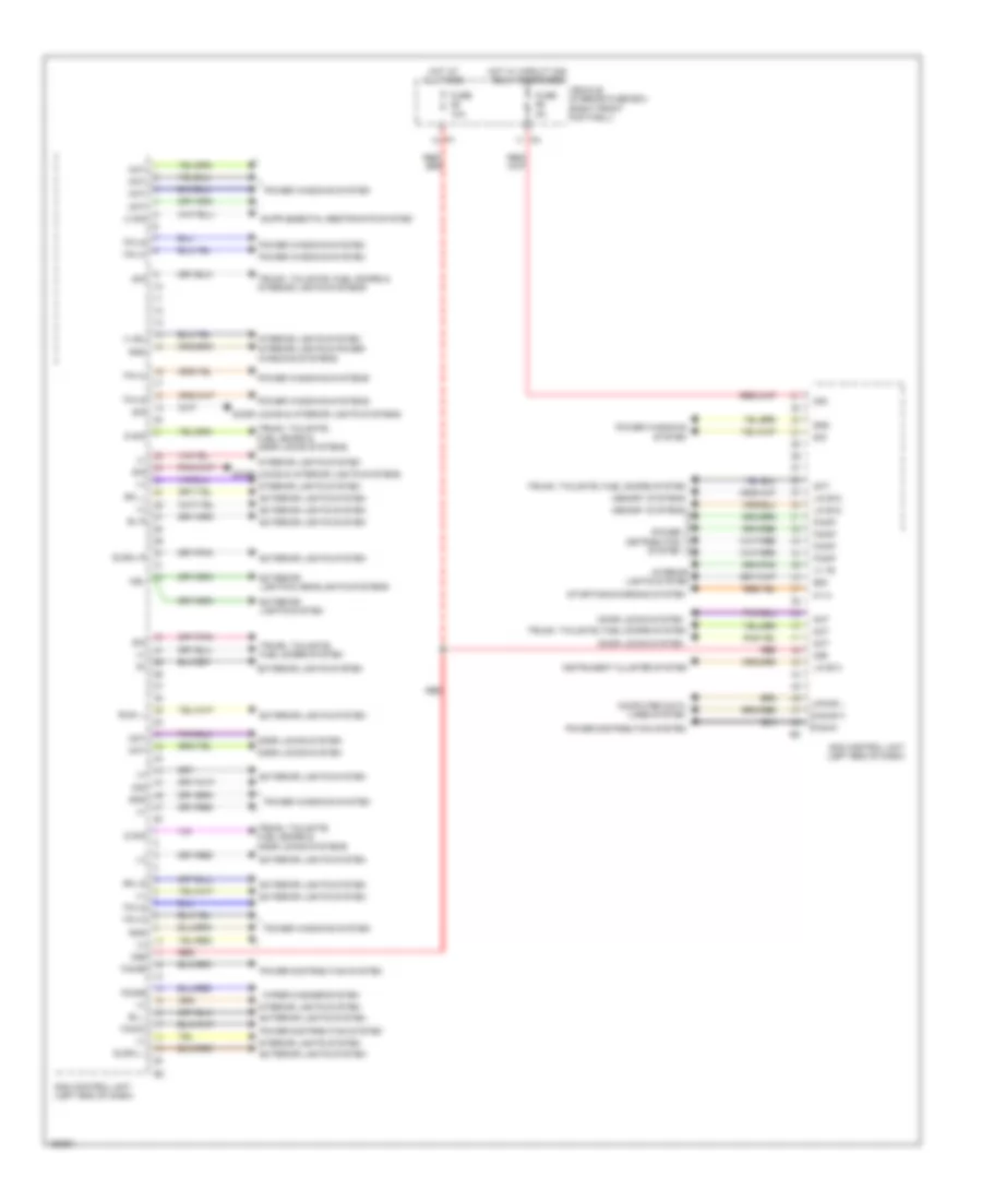
Body Control Modules Wiring Diagram (1 of 2) for Mercedes-Benz CLA250 4Matic 2014
List of elements for Body Control Modules Wiring Diagram (1 of 2) for Mercedes-Benz CLA250 4Matic 2014:
- (+)
- (+) bu
- (+) ye
- 30b
- 30g
- 58d
- Bl l
- Bl r
- Blsl l
- C sig
- Can-b h
- Can-b l
- Computer data lines system
- Door locks & interior lights systems
- Door locks system
- Exterior lights & headlights systems
- Exterior lights system
- F34ka
- F34kb
- F34kc
- F34ke
- F34kf
- Fuse 10a
- Fuse 5a
- Gnd
- Hot at all times
- Hot w/ circuit 30g relay energized
- Instrument cluster system
- Interior lights system
- Interior lights system interior lights & power windows systems
- K114
- Lin b12
- Lin b13
- Memory systems
- Mot
- Nsl
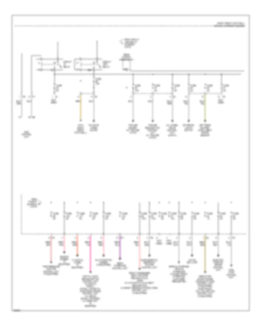
- Power distribution system
- Power windows system
- Power windows systems
- Red
- Rfl l
- Rfl r
- S sig
- Sam control unit (left end of dash)
- Sig
- Slsml l
- Slsml r
- Starting/charging system
- Tfh o
- Tfh s
- Trunk, tailgate, fuel doors & door locks systems
- Trunk, tailgate, fuel doors & interior lights systems
- Trunk, tailgate, fuel doors system
- Vehicle interior fuse box (right front footwell)
- Wiper/washer system
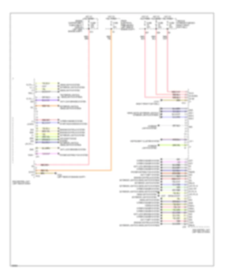
Body Control Modules Wiring Diagram (2 of 2) for Mercedes-Benz CLA250 4Matic 2014
List of elements for Body Control Modules Wiring Diagram (2 of 2) for Mercedes-Benz CLA250 4Matic 2014:
- (+)
- 30 ab
- 30 fh
- 30 ib sra
- 30 zv
- 30l
- 58d
- Air conditioning system exterior lights & headlights systems
- Anti-lock brakes system
- Anti-theft system
- Engine compartment fuse & relay module (left side engine compt)
- Engine controls system
- Exterior lights & headlights systems
- Exterior lights system
- F32k1
- F58kj
- F58kk
- F58kl
- F58kr
- Fl l
- Fra l
- Fra r
- Front electrical prefuse box (left side of engine compt)
- Fuse 30a
- Fuse 40a
- Gnd
- Headlights system
- Headlights, exterior lights & interior lights systems
- Horns system
- Hot at all times
- Instrument cluster system
- Interior lights system
- Lin 1
- Lin b15
- Mot
- Pltfl l
- Pltfl r
- Power distribution system
- Pw1
- Pw2
- Red
- S13
- S27
- S28
- Sam control unit (left end of dash)
- Sig
- Sig 1
- Sig 2
- Sig 3
- Starting/charging system
- Uh1
- Uh2
- Upltfl l
- Upltfl r
- Vehicle interior fuse box (right front footwell)
- W15/1 (right front footwell)
- W3/2 (left rear of engine compt)
- Wiper/washer system
- Wmv pp
- Wsa
COMPUTER DATA LINES
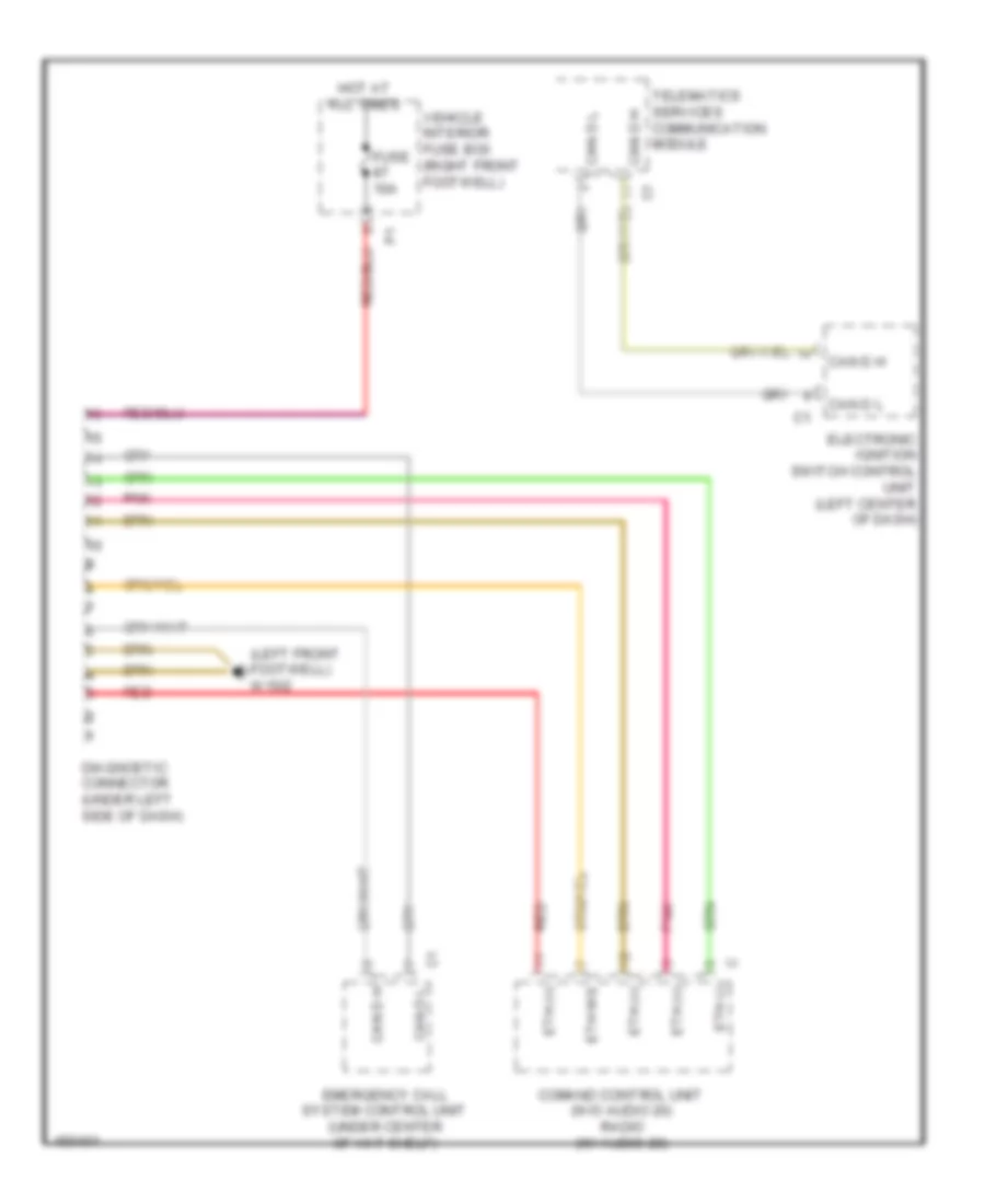
Data Link Connector Wiring Diagram for Mercedes-Benz CLA250 4Matic 2014
List of elements for Data Link Connector Wiring Diagram for Mercedes-Benz CLA250 4Matic 2014:
- (left front footwell) w15/2
- Can d h
- Can d l
- Comand control unit (w/o audio 20) radio (w/ audio 20)
- Diagnostic connector (under left side of dash)
- Electronic ignition switch control unit (left center of dash)
- Emergency call system control unit (under center of hat shelf)
- Eth (+)
- Eth (-)
- Eth ws
- Fuse 10a
- Hot at all times
- Pnk
- Red
- Telematics services communication module
- Vehicle interior fuse box (right front footwell)
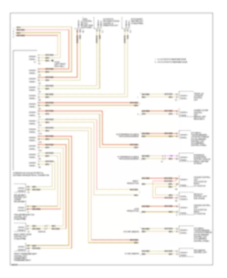
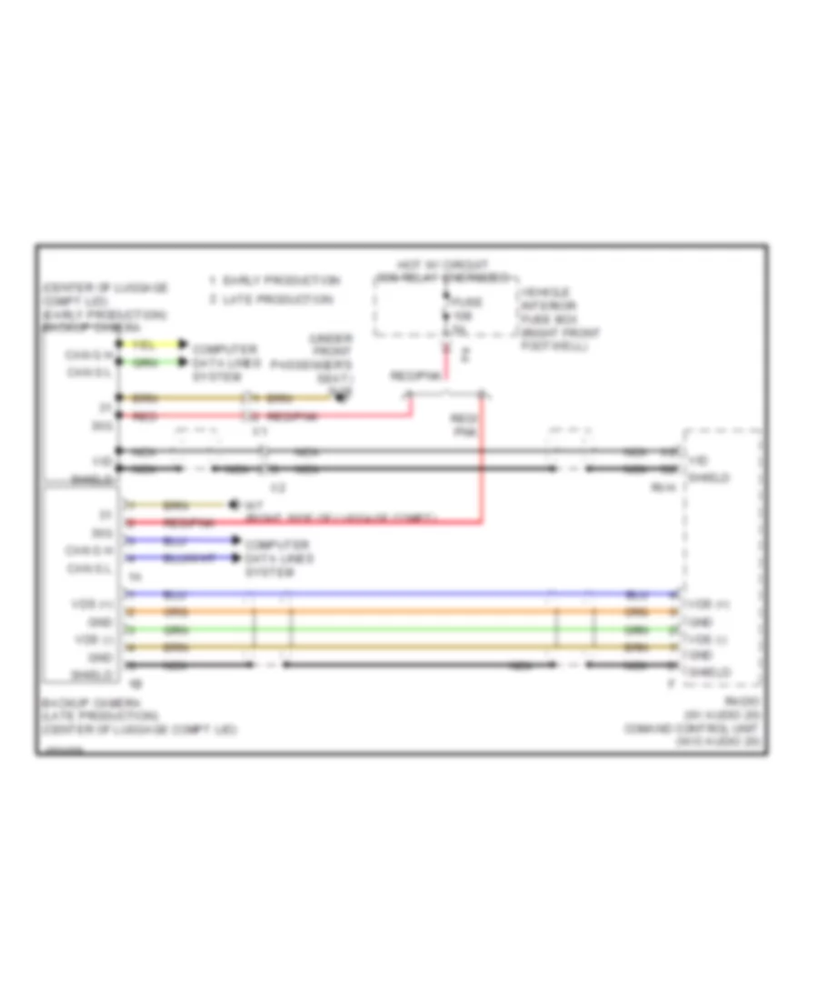
High/Low Bus Wiring Diagram (1 of 3) for Mercedes-Benz CLA250 4Matic 2014
List of elements for High/Low Bus Wiring Diagram (1 of 3) for Mercedes-Benz CLA250 4Matic 2014:
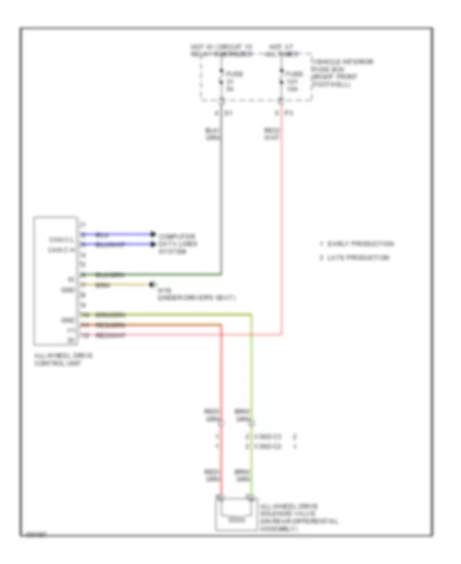
- All-wheel drive control unit (if equipped)
- Audio/comand control panel
- Audio/comand display
- Backup camera (center of luggage compt lid)
- C1a
- Can-a h
- Can-a l
- Can-b h
- Can-b l
- Can-c h
- Can-c l
- Can-e h
- Can-e l
- Can-g h
- Can-g l
- Comand control unit (w/o audio 20) radio (w/o audio 20)
- Cradle for navigation module (if equipped)
- Drive kit control unit for iphone (if equipped)
- Drivetrain can (can c) potential distributor electrical connector
- Dual clutch transmission fully integrated transmission control controller unit (if equipped) (in transmission)
- Early production
- Electronic ignition switch control unit (left center of dash)
- Front end can (can g) potential distributor electrical connector
- Fuel pump control unit (behind right rear seat)
- Headlamp control unit (upper right footwell)
- Late production
- Left rear bumper intelligent radar sensor (w/ blind spot assist) (behind left rear end of rear bumper)
- Me-sfi (me) control unit (left front of engine compt)
- Multi-function camera (if equipped) (top center of windshield)
- Right rear bumper intelligent radar sensor (w/ blind spot assist) (behind right rear end of rear bumper)
- Telematics can (can a) potential distributor electrical connector
- W12 (under left front of center console)
- W15/1 (right front footwell)
- W15/2 (left front footwell)
- X1/61-c1
- X138/1-c1
- X172/2-c1
High/Low Bus Wiring Diagram (2 of 3) for Mercedes-Benz CLA250 4Matic 2014
List of elements for High/Low Bus Wiring Diagram (2 of 3) for Mercedes-Benz CLA250 4Matic 2014:
- C10
- C11
- C12
- C13
- Can-e h
- Can-e l
- Chassis can (can e) potential distributor electrical connector
- Distronic electric controller unit (w/ distronic plus) collision prevention assist controller unit (w/o distronic plus) (w/ distronic plus: behind center of front grille) (w/o distronic plus: behind right side of front bumper)
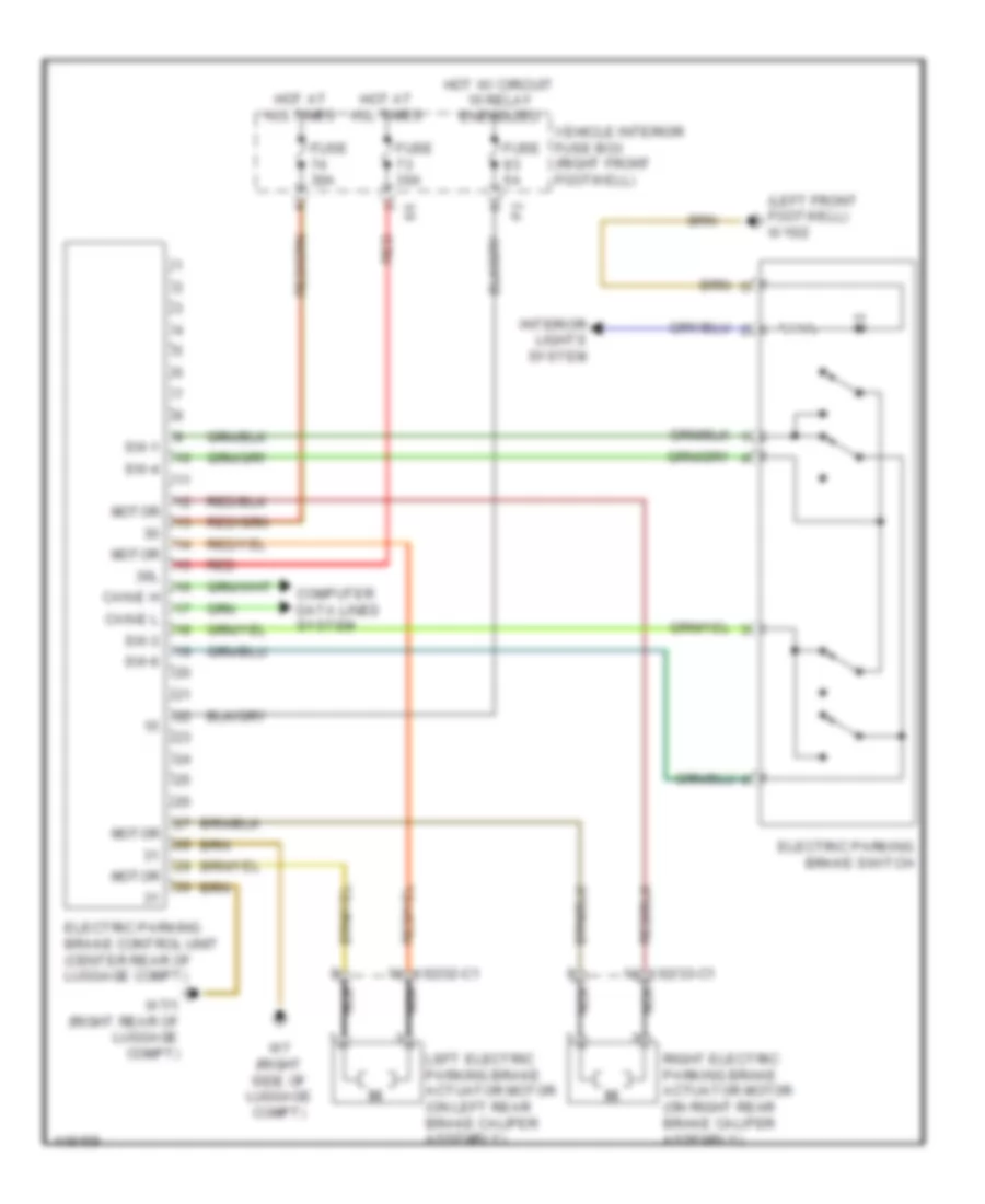
- Electric parking brake control unit (center rear of luggage compt)
- Electrical power steering control unit (on steering rack assembly)
- Electronic stability program control unit (left front of engine compt)
- Instrument cluster
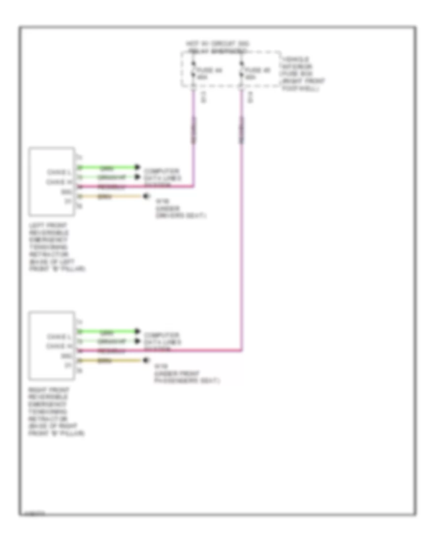
- Left front reversible emergency tensioning retractor (if equipped) (base of left front "b" pillar)
- Parking system control unit (if equipped) (under front of center console)
- Right front reversible emergency tensioning retractor (if equipped) (base of right front "b" pillar)
- Steering column module control unit (top of steering column)
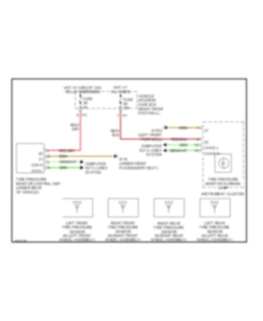
- Tire pressure monitor control unit (if equipped) (under rear of vehicle)
- W/ distronic plus
- W/collision warning system & active park assist
- W/o collision warning system & active park assist
- W15/1 (right front footwell)
- X213/3-c1
- X26/27-c2
- X26/27-c3
High/Low Bus Wiring Diagram (3 of 3) for Mercedes-Benz CLA250 4Matic 2014
List of elements for High/Low Bus Wiring Diagram (3 of 3) for Mercedes-Benz CLA250 4Matic 2014:
- Ata (edw)/ towing sensor/ liftgate interior motion sensor control unit (in overhead control panel)
- Automatic air conditioning control & operating unit
- C10
- C11
- C12
- C13
- Camera cover control unit (behind left rear seat)
- Can-b h
- Can-b l
- Comand control unit (w/o audio 20) radio (w/ audio 20)
- Drive kit control unit for iphone
- Driver seat control unit (under driver seat)
- Early production
- Front passenger seat control unit (under front passenger seat)
- Interior can (can b) potential distributor electrical connector
- Keyless-go control unit
- Late production
- Panoramic sliding roof control module (front center of roof)
- Right front door control unit (if equipped)
- Sam control unit (left end of dash)
- Stationary heater unit (if equipped)
- Trailer recognition control unit (if equipped)
- Trunk lid/ liftgate control unit
- W/ automatic rear end door
- W/ keyless-go
- W/ panaromic glass & top sliding sunroof
- W/o automatic rear end door
- W/o keyless-go
- W/o panaromic glass & top sliding sunroof
- W15/2 (left front footwell)
- X35/2-c2
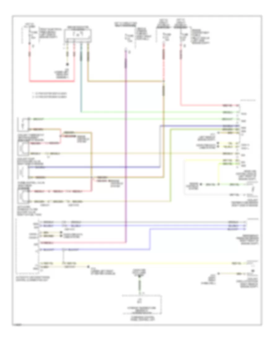
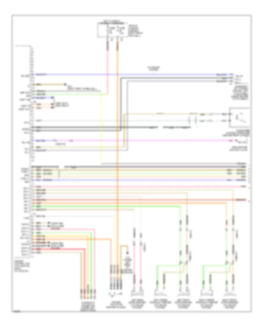
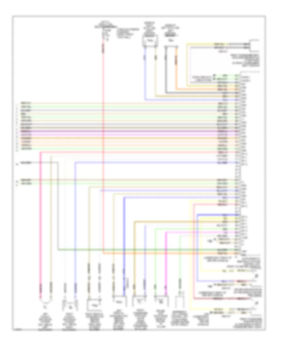
COOLING FAN
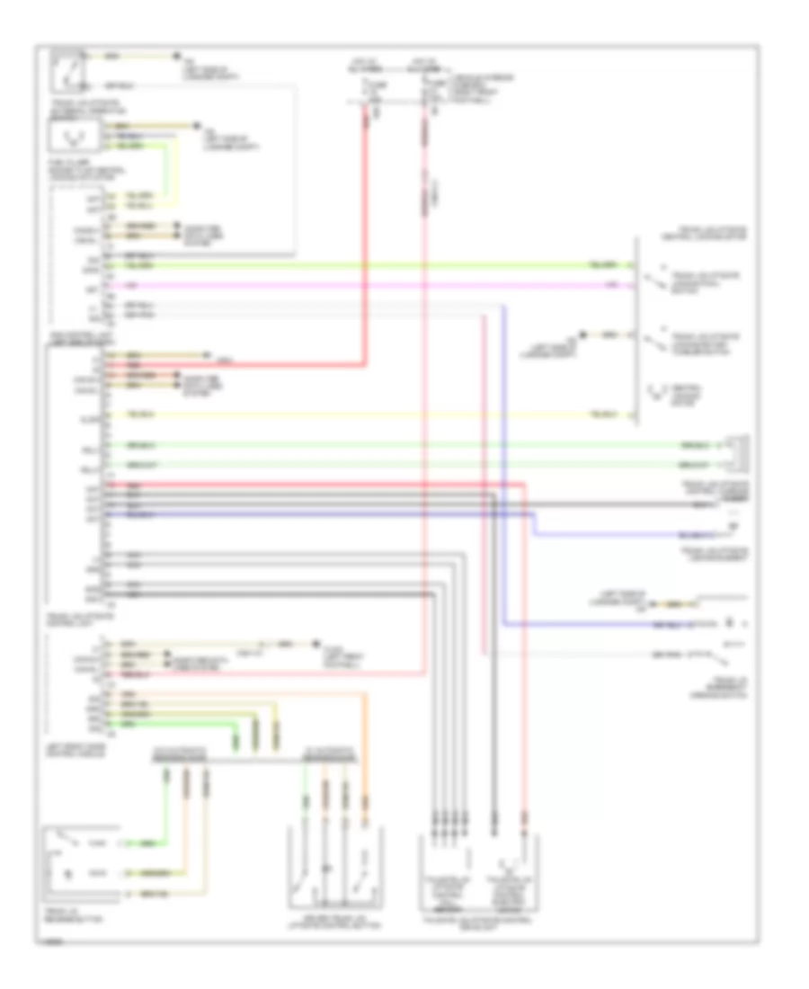
Cooling Fan Wiring Diagram for Mercedes-Benz CLA250 4Matic 2014
List of elements for Cooling Fan Wiring Diagram for Mercedes-Benz CLA250 4Matic 2014:
- (+)
- (behind radiator) fan motor
- 30g
- Activated charcoal filter shutoff valve (right of fuel tank)
- Automatic air conditioning control & operating unit
- Can-b h
- Can-b l
- Can-i h
- Can-i l
- Computer data lines system
- Coolant circulation pump (right rear of engine compt)
- Coolant pump switchover valve (right side of engine)
- Coolant temperature sensor (right side of engine)
- Coolant thermostat heating element (right side of engine)
- Engine compartment fuse & relay module (left side engine compt)
- Engine controls system
- Front electrical prefuse box (left side of engine compt)
- Fuse 15a
- Fuse 5a
- Fuse 7.5a
- Fuse 80a
- Gnd
- Hot at all times
- Hot w/ circuit 30g relay energized
- Hot w/ circuit 87m relay energized
- Interior temperature sensor w/ integrated fan
- Lin b13
- Me-sfi (me) control module (left front of engine compt)
- Overhead control panel control unit
- Purge control valve (right rear of engine)
- Pwm
- Red
- Refrigerant pressure sensor (right front of engine compt)
- Sig
- Vehicle interior fuse box (right front footwell)
- W/ fan motor 300w & 400w
- W/ fan motor 600w & 850w
- W11 (left rear of engine compt)
- W12 (under left front of center console)
- W3/1 (right front wheelwell)
- W9 (under left headlight assembly)
- X25/13-c2
- X25/14-c1
- X36/2-c1
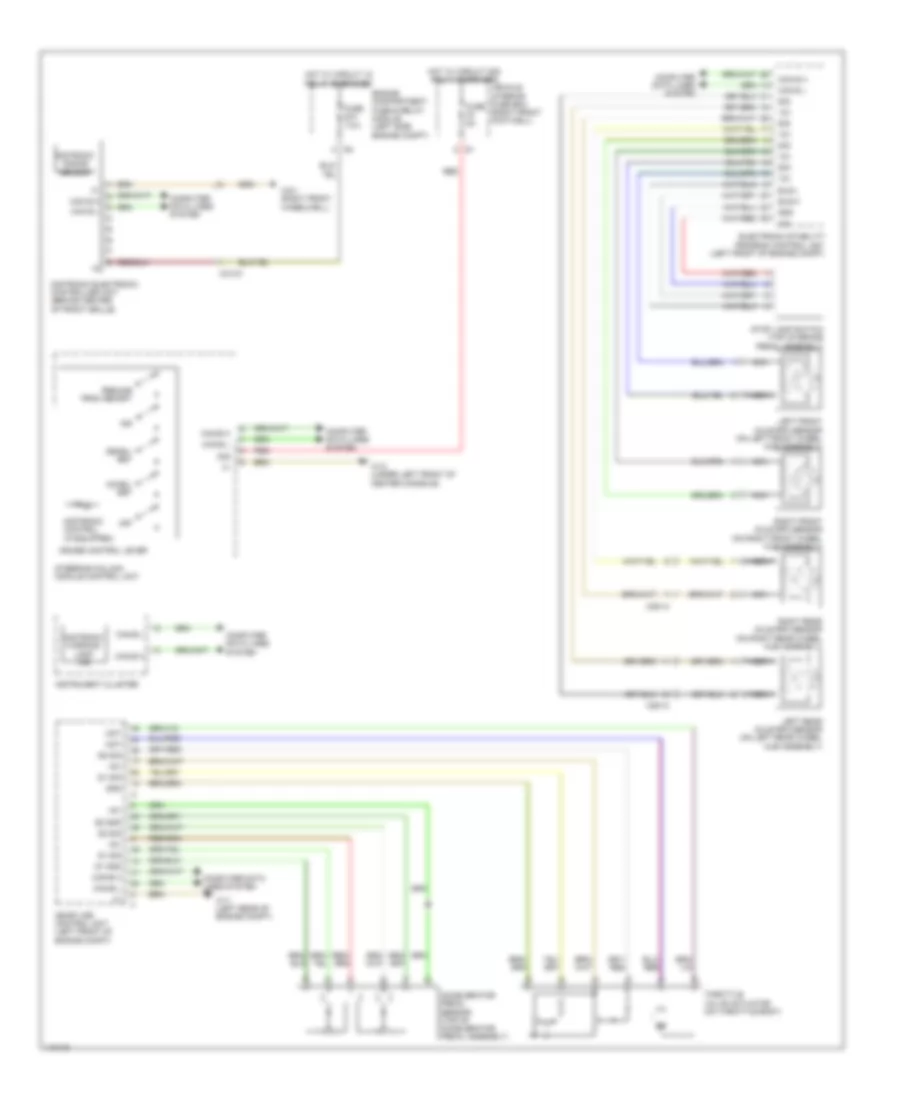
CRUISE CONTROL
Cruise Control Wiring Diagram for Mercedes-Benz CLA250 4Matic 2014
List of elements for Cruise Control Wiring Diagram for Mercedes-Benz CLA250 4Matic 2014:
- +5v
- 12v
- 30g
- Accel/ set
- Accelerator pedal sensor (top of accelerator pedal assembly)
- Bls-h
- Bls-l
- Can e h
- Can e l
- Can-e h
- Can-e l
- Computer data lines system
- Cruise control lever
- Decel/ set
- Distronic control (if equipped)
- Distronic electronic controller unit (behind center of front grille)
- Distronic radar sensor
- Distronic warning lamp ind
- Electronic stability program control unit (left front of engine compt)
- Engine compartment fuse & relay module (left side engine compt)
- Fuse 5a
- Fuse 7.5a
- Gnd
- Hot w/ circuit 15 relay energized
- Hot w/ circuit 30g relay energized
- Ind
- Instrument cluster
- Left front axle rpm sensor (on left front wheel hub assembly)
- Left rear axle rpm sensor (on left rear wheel hub assembly)
- Me-sfi (me) control unit (left front of engine compt)
- Mot
- Nca
- Off
- Red
- Resume from memory
- Right front axle rpm sensor (on right front wheel hub assembly)
- Right rear axle rpm sensor (on right rear wheel hub assembly)
- S1 gnd
- S1 sig
- S2 gnd
- S2 sig
- Sig
- Steering column module control unit
- Stop lamp switch (top of brake pedal assembly)
- Throttle valve actuator (on throttle body)
- Vehicle interior fuse box (right front footwell)
- W11 (left rear of engine compt)
- W12 (under left front of center console)
- W3/1 (right front wheelwell)
- X213/3
- X25/13
- X25/14
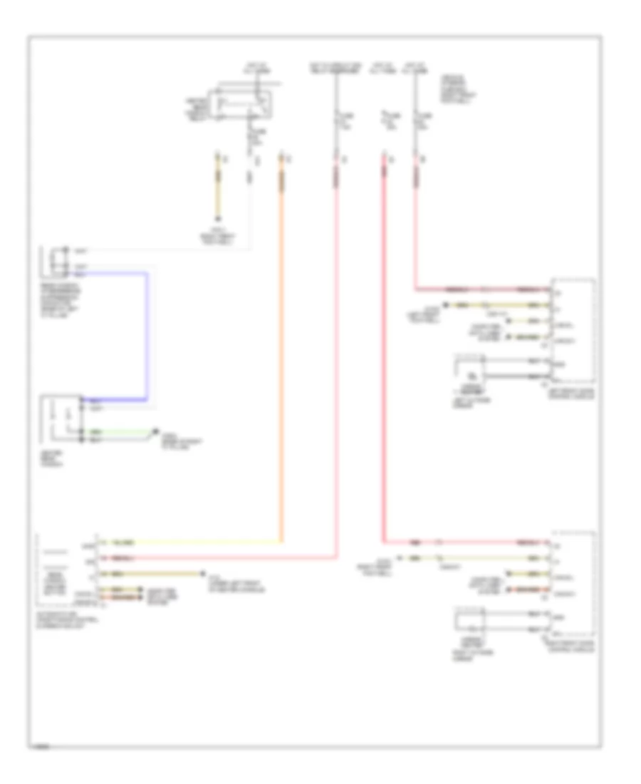
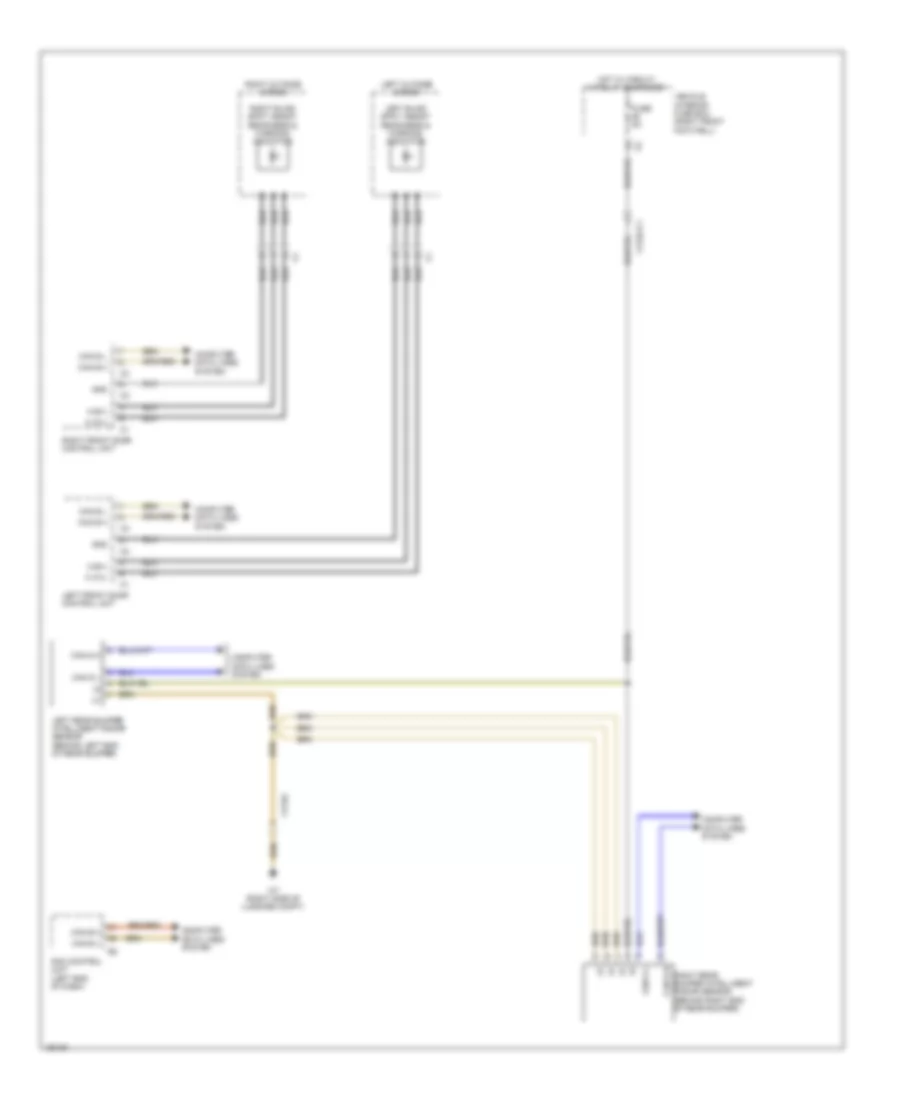
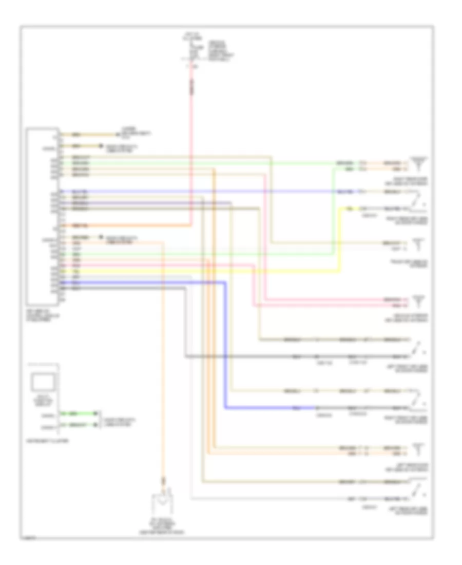
DEFOGGERS
Defoggers Wiring Diagram for Mercedes-Benz CLA250 4Matic 2014
List of elements for Defoggers Wiring Diagram for Mercedes-Benz CLA250 4Matic 2014:
- & operating unit
- (+)
- (-)
- 30g
- 34kd
- Automatic air conditioning control
- Can b h
- Can b l
- Computer data lines system
- Fuse 30a
- Fuse 40a
- Fuse 7.5a
- Gnd
- Heated rear window
- Heated rear window relay
- Hot at all times
- Hot w/ circuit 30g relay energized
- Left front door control module
- Left outside mirror
- Mirror heater
- Rear window heater button
- Rear window interference suppression capacitor (base of left "c" pillar)
- Red
- Right front door control module
- Right outside mirror
- S11
- Vehicle interior fuse box (right front footwell)
- W12 (under left front of center console)
- W15/1 (right front footwell)
- W15/2 (left front footwell)
- W29/4 (base of right "c" pillar)
- X35/1-c1
- X35/2-c1
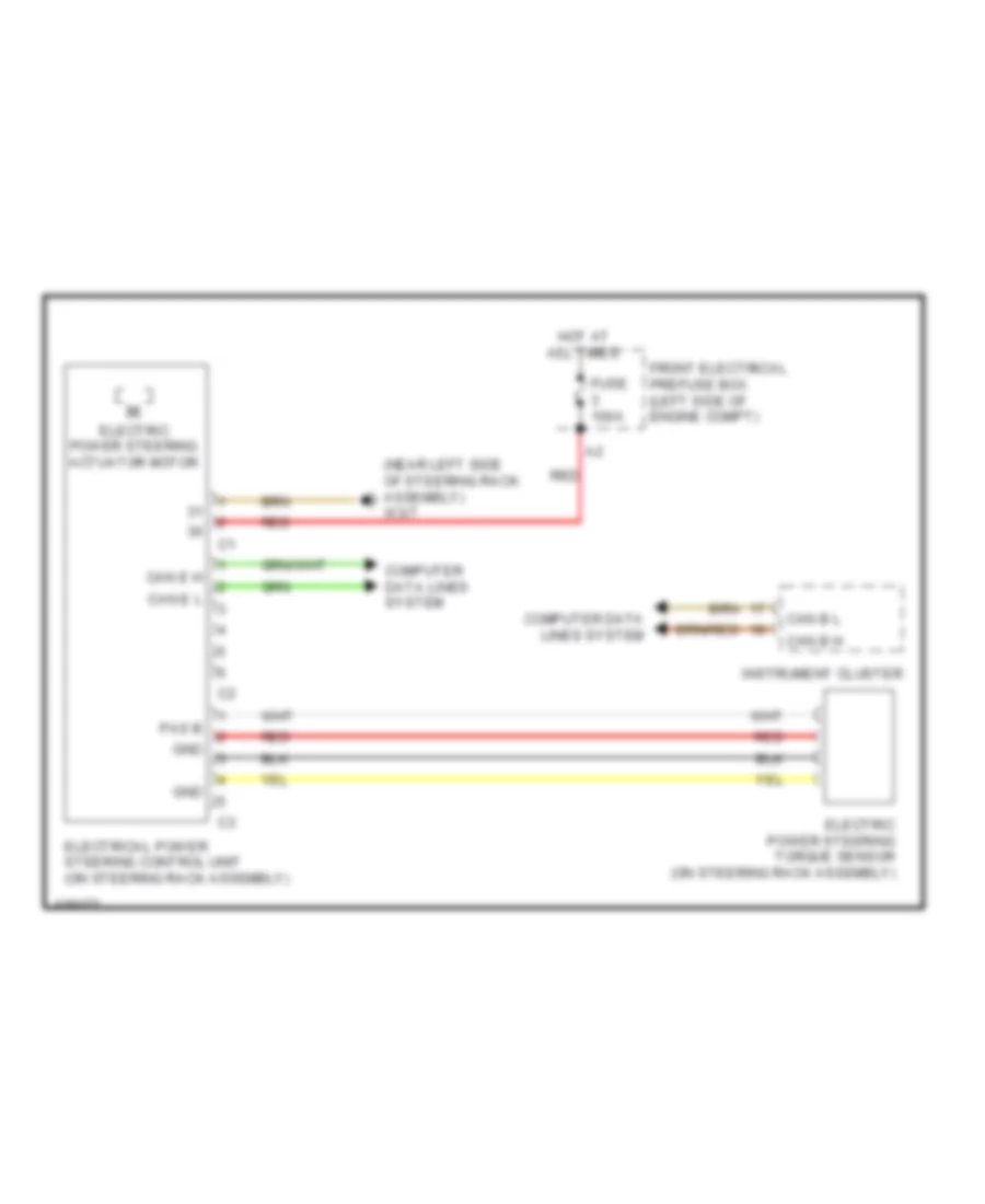
ELECTRONIC POWER STEERING
Electronic Power Steering Wiring Diagram for Mercedes-Benz CLA250 4Matic 2014
List of elements for Electronic Power Steering Wiring Diagram for Mercedes-Benz CLA250 4Matic 2014:
- (near left side of steering rack assembly) w3/7
- Can b h
- Can b l
- Can e h
- Can e l
- Computer data lines system
- Electric power steering actuator motor
- Electric power steering torque sensor (on steering rack assembly)
- Electrical power steering control unit (on steering rack assembly)
- Front electrical prefuse box (left side of engine compt)
- Fuse 100a
- Gnd
- Hot at all times
- Instrument cluster
- Pas b
- Red
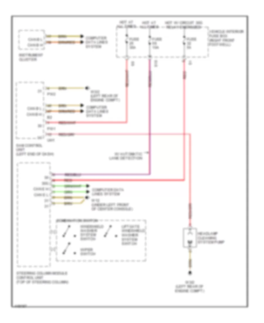
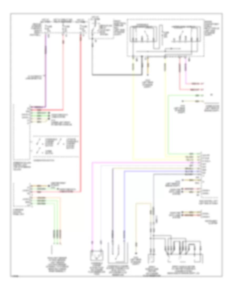
Power Steering Column Wiring Diagram for Mercedes-Benz CLA250 4Matic 2014
List of elements for Power Steering Column Wiring Diagram for Mercedes-Benz CLA250 4Matic 2014:
- (+)
- (in steering wheel) driver air bag squib 1
- (in steering wheel) driver air bag squib 2
- 30g
- 58d
- Accelerate & set switch
- Accept/terminate phone call button
- Back & voice control system off button
- Button + & - for setting specific functions & volume control
- Can-e h
- Can-e l
- Center horns button
- Combination switch
- Computer data lines system
- Cruise control lever
- Decelerate & set switch
- Direct select lever
- Distronic control (if equipped)
- Fuse 10a
- Fuse 5a
- Gnd
- Headlamp flasher/high beam switch liftgate windshield washer system switch
- Hot at all times
- Hot w/ circuit 30g relay energized
- Indicator switch
- Left fanfare horn system button
- Left multi-function steering wheel button group
- Low beam switch
- Mute button
- Off switch
- Ok button
- Pnk
- Red
- Reset and 'back' button
- Resume from memory switch
- Right fanfare horn system button
- Right multi-function steering wheel button group
- S18
- Scroll forward/ back button
- Sig
- Steering column module control unit (top of steering column)
- Steering wheel angle sensor
- Steering wheel clock spring contact (part of steering column module)
- Steering wheel downshift button (if equipped)
- Steering wheel electronics (in steering wheel)
- Steering wheel upshift button (if equipped)
- Steering wheel vibration motor (in bottom steering wheel spoke)
- System selection button
- Turn signal lamp switch
- Vehicle interior fuse box (right front footwell)
- Voice control system on button
- W/ automatic lane detection
- W12 (under left front of center console)
- Windshield washer system switch
- Wipe switch
ENGINE ACCESSORIES
Stationary Heater Wiring Diagram for Mercedes-Benz CLA250 4Matic 2014
List of elements for Stationary Heater Wiring Diagram for Mercedes-Benz CLA250 4Matic 2014:
- (+)
- (left end of dash) sam control unit
- (left front footwell)
- A tel
- Can b h
- Can b l
- Computer data lines system
- Coolant circulation pump (w/o comfort automatic air conditioning) (right rear of engine compt)
- Engine compartment fuse & relay module (left side engine compt)
- Fuse 20a
- Fuse 5a
- Hot at all times
- Lin 1
- Mobile phone & stationary heater radio remote control antenna splitter
- Mobile phone contact plate
- Multi-function antenna
- Nca
- Red
- Shd
- Shd a sdar
- Sig
- Stationary heater button
- Stationary heater fuel pump
- Stationary heater radio remote control receiver
- Stationary heater switchover valve
- Stationary heater unit
- Upper control panel control unit
- Vehicle interior fuse box (right front footwell)
- W/ comfort telephony
- W/o comfort telephony
- W12 (under left front of center console)
- W15/2
- W3/1 (right front wheelwell)
- W7 (right side of luggage compt)
- X25/14-c2
- X36/2-c1
- X39/37-c1
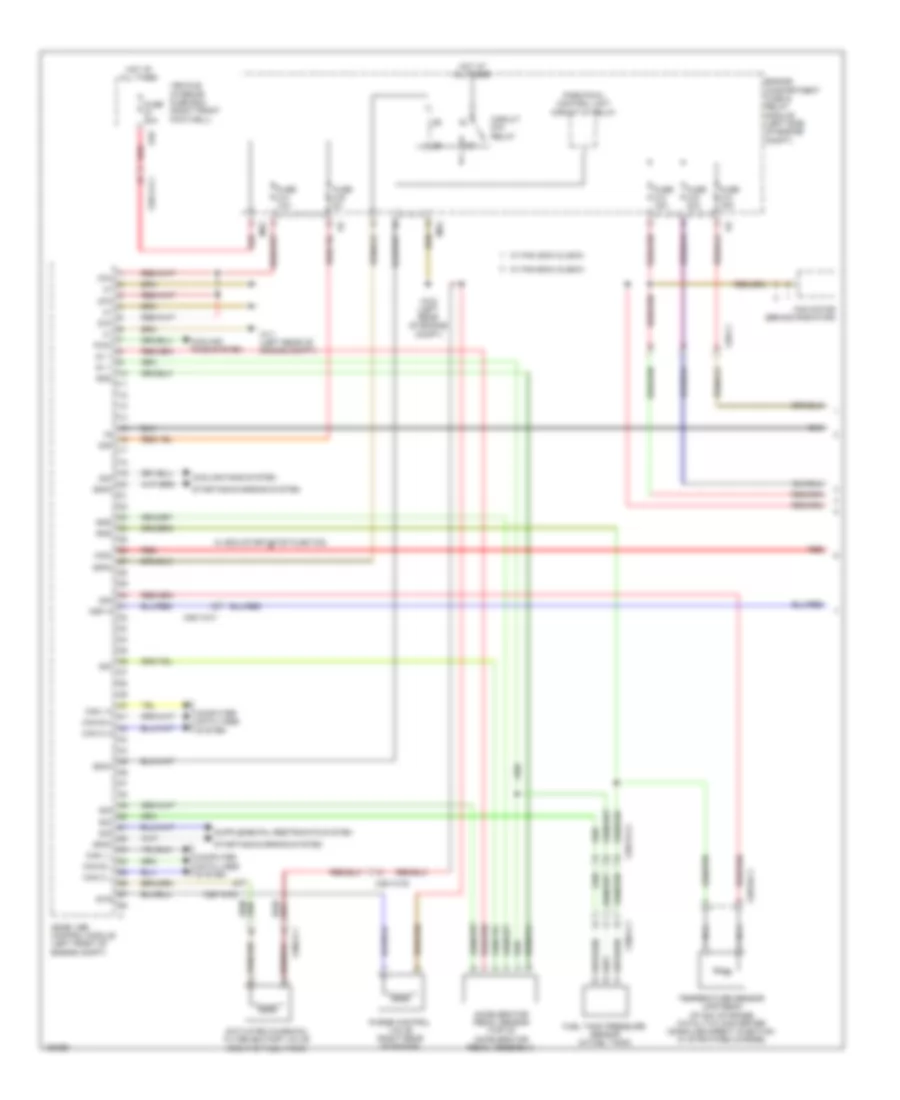
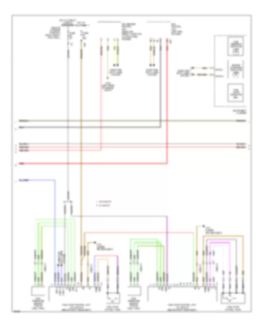
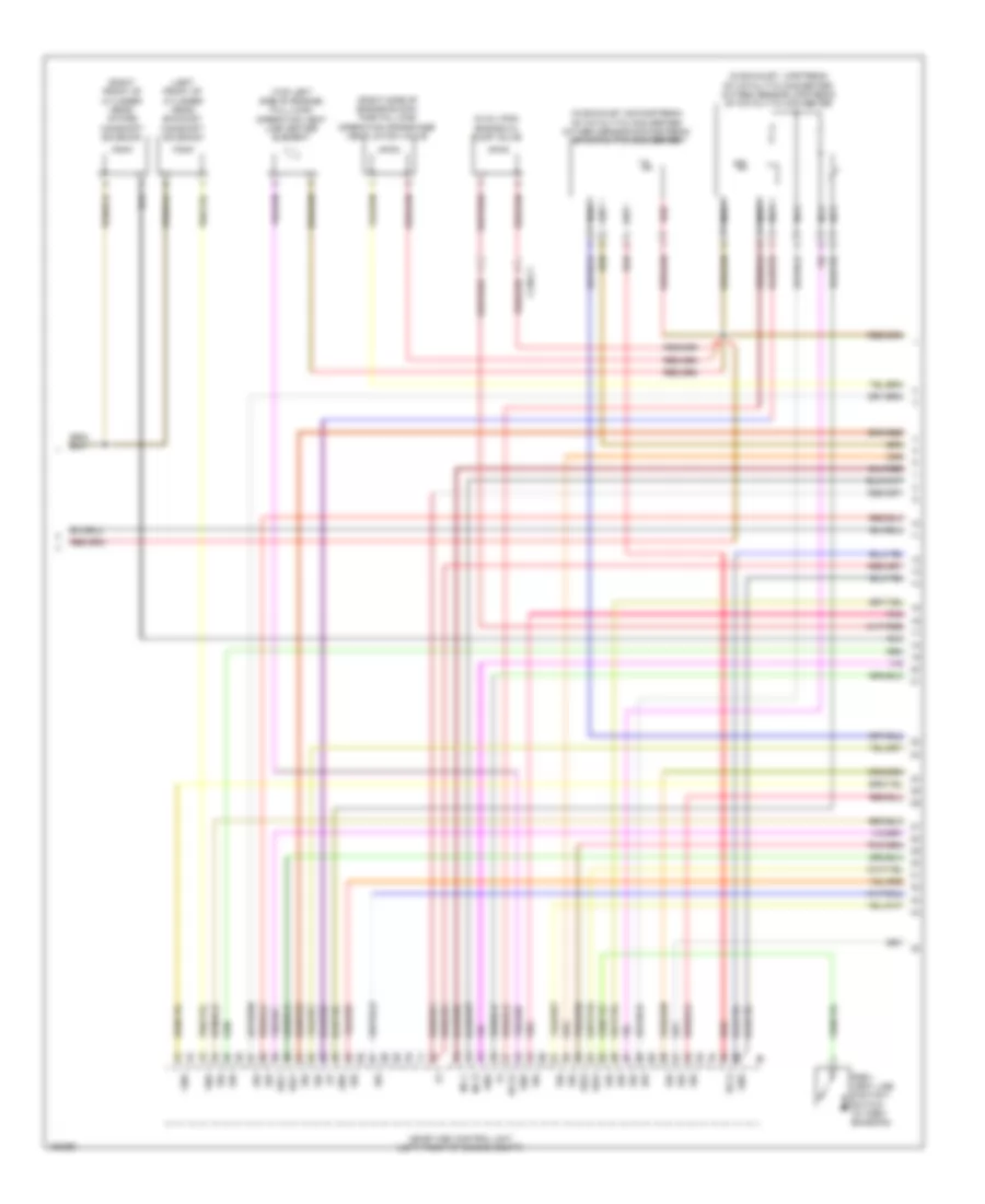
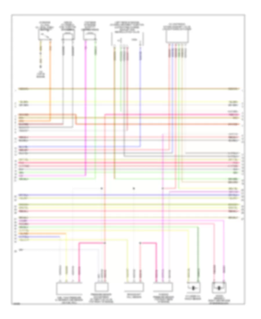
ENGINE PERFORMANCE
2.0L TURBO
2.0L Turbo, Engine Performance Wiring Diagram (1 of 7) for Mercedes-Benz CLA250 4Matic 2014
List of elements for 2.0L Turbo, Engine Performance Wiring Diagram (1 of 7) for Mercedes-Benz CLA250 4Matic 2014:
- 30g
- 58km
- 58kn
- 58ko
- 5v +
- 87m
- Accelerator pedal sensor (top of accelerator pedal assembly)
- Activated charcoal filter shutoff valve (right of fuel tank)
- Can c h
- Can c l
- Can e h
- Can e l
- Can i h
- Can i l
- Circuit 87m relay
- Computer data lines system
- Cooling fans system
- Engine compartment fuse & relay module (left side of engine compt)
- Fan motor (behind radiator)
- Fuel tank pressure sensor (in fuel tank)
- Fuse 10a
- Fuse 15a
- Fuse 20a
- Fuse 30a
- Fuse 5a
- Gnd
- Hot at all times
- Ksp a
- Me-sfi (me) control module (left front of engine compt)
- Mr2
- Nca
- Park pawl control unit circuit 87 relay
- Purge control valve (right rear of engine)
- Pwm
- Red
- S10
- Sig
- Starting/charging system
- Str
- Temperature sensor upstream of nox storage catalytic converter (gasoline direct injection w/ stratified charge)
- Vehicle interior fuse box (right front footwell)
- W/ eco start/stop function
- W/ fan 300w & 400w
- W/ fan 600w & 850w
- W11 (left rear of engine compt)
- W3/2 (left rear of engine compt)
- Wsa
- X25/13-c1
- X25/13-c2
- X25/14-c1
- X25/18-c1
- X26-c1
- X36/2-c1
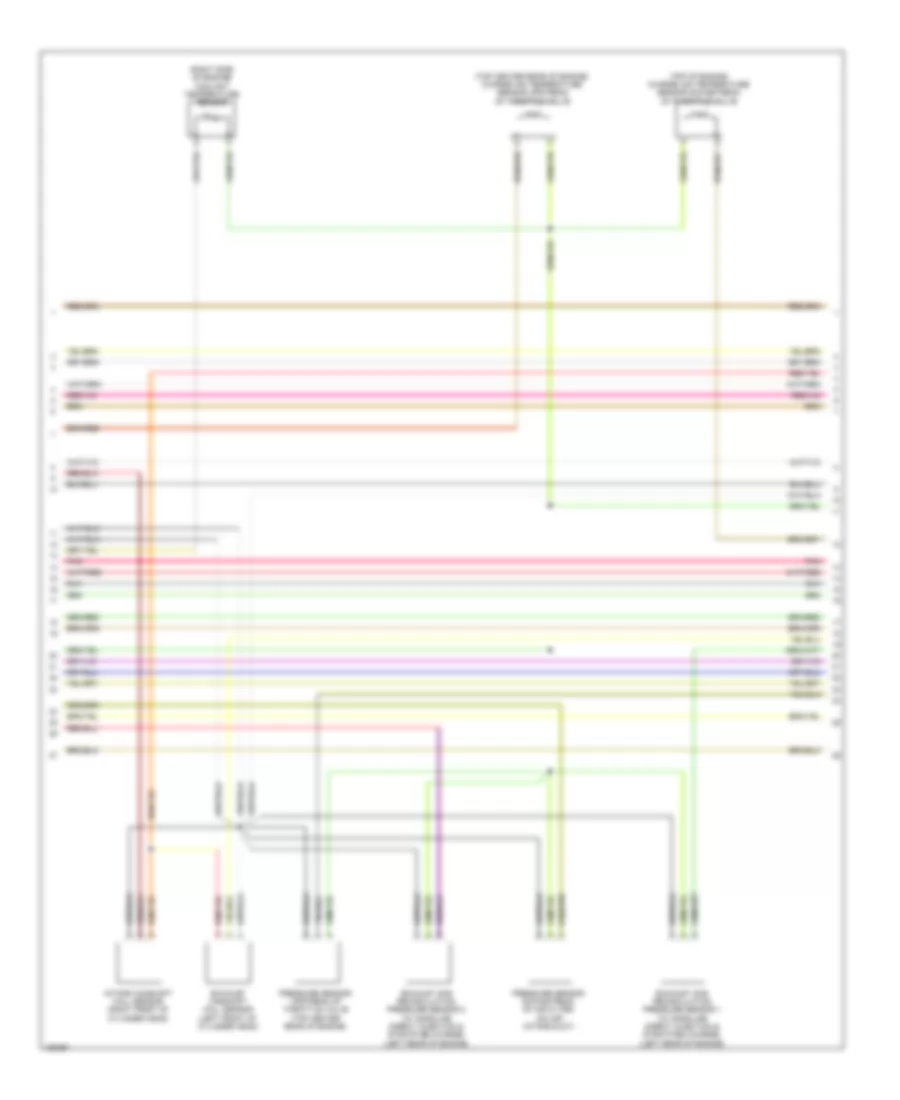
2.0L Turbo, Engine Performance Wiring Diagram (2 of 7) for Mercedes-Benz CLA250 4Matic 2014
List of elements for 2.0L Turbo, Engine Performance Wiring Diagram (2 of 7) for Mercedes-Benz CLA250 4Matic 2014:
- (+)
- 5v +
- Can b h
- Can b l
- Can c h
- Can c l
- Computer data lines system
- Engine diagnosis indicator lamp
- Fuel level indicator
- Fuel pressure sensor (top of fuel tank)
- Fuel pump (in fuel tank)
- Fuel pump control unit (w/ 4matic) (behind right rear seat)
- Fuel pump control unit (w/o 4matic) (behind right rear seat)
- Fuel reserve indicator lamp
- Fuse 25a
- Fuse 5a
- Gnd
- Hot at all times
- Hot w/ circuit 15 relay energized
- Instrument cluster
- Ksp a
- Nca
- Nox sensor control unit (gasoline direct injection w/ stratified charge)
- Pwm
- Red
- S25
- Sam control unit (left end of dash)
- Sig
- System data lines computer
- Uh2
- Vehicle interior fuse box (right front footwell)
- W/ 4matic
- W/o 4matic
- W18 (under driver's seat)
- W3/2 (left rear of engine compt)
- X36/2-c1
2.0L Turbo, Engine Performance Wiring Diagram (3 of 7) for Mercedes-Benz CLA250 4Matic 2014
List of elements for 2.0L Turbo, Engine Performance Wiring Diagram (3 of 7) for Mercedes-Benz CLA250 4Matic 2014:
- (+)
- (in exhaust, downstream of catalytic converter) oxygen sensor downstream of catalytic converter
- (in exhaust, upstream of catalytic converter) oxygen sensor upstream of catalytic converter
- (in oil pan) engine oil pump valve
- (left front of cylinder head) exhaust camshaft solenoid
- (right front of cylinder head) intake camshaft solenoid
- (right side of engine block) partial load operation crankcase ventilation valve
- (top left side of engine) full-load operation vent line heater element
- Gnd
- He (+)
- He (-)
- Inj h
- Inj l
- Me-sfi (me) control unit (left front of engine compt)
- Nca
- Pnk
- Pzev vent line contact switch (w/ pzev emission)
- Red
- Sig
- Sig1
- Sig2
- X130-c1
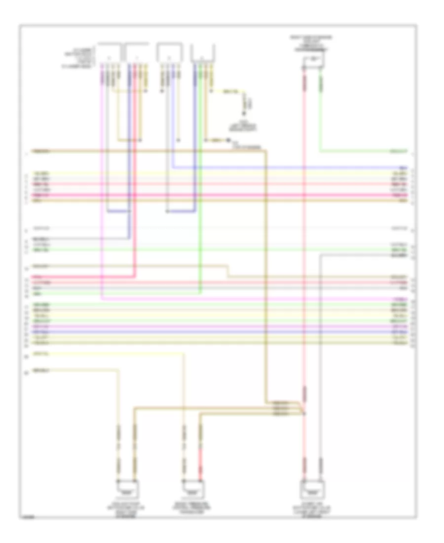
2.0L Turbo, Engine Performance Wiring Diagram (4 of 7) for Mercedes-Benz CLA250 4Matic 2014
List of elements for 2.0L Turbo, Engine Performance Wiring Diagram (4 of 7) for Mercedes-Benz CLA250 4Matic 2014:
- (above cylinder 2) fuel injector cylinder 2
- (in engine oil pan) oil level check switch
- (left rear of engine) (w/ gasoline direct injection & stratified charge) exhaust gas recirculation valve
- (top rear of engine) quantity control valve
- (w/ camtronic) intake camshaft valve lift switching actuator
- Crankshaft hall sensor
- Cylinder 3+4 knock sensor
- Fuel tank pressure & temperature sensor (on fuel rail)
- Knock sensor 2 (right center side of engine block)
- Pnk
- Pressure sensor downstream of throttle valve (top front of engine)
- Purging pressure sensor (top right rear of engine)
- W2 (top of engine)
2.0L Turbo, Engine Performance Wiring Diagram (5 of 7) for Mercedes-Benz CLA250 4Matic 2014
List of elements for 2.0L Turbo, Engine Performance Wiring Diagram (5 of 7) for Mercedes-Benz CLA250 4Matic 2014:
- (right side of engine) coolant temperature sensor
- (top center rear of engine) charge air temperature sensor upstream of throttle valve
- (top of engine) charge air temperature sensor downstream of throttle valve
- Exhaust camshaft hall sensor (left front of cylinder head)
- Exhaust gas recirculation pressure sensor 1 (w/ gasoline direct injection & stratified charge) (left rear of engine)
- Exhaust gas recirculation pressure sensor 2 (w/ gasoline direct injection & stratified charge) (left rear of engine)
- Intake camshaft hall sensor (right front of cylinder head)
- Pnk
- Pressure sensor downstream of air filter (on air intake duct)
- Pressure sensor upstream of throttle valve (top center rear of engine)
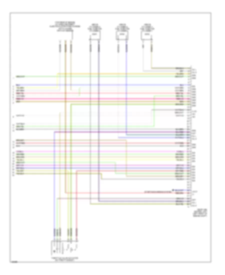
2.0L Turbo, Engine Performance Wiring Diagram (6 of 7) for Mercedes-Benz CLA250 4Matic 2014
List of elements for 2.0L Turbo, Engine Performance Wiring Diagram (6 of 7) for Mercedes-Benz CLA250 4Matic 2014:
- (right side of engine) coolant thermostat heating element
- Boost pressure control pressure transducer
- Coolant pump switchover valve (right side of engine)
- Cylinder ignition coils 1, 2, 3 & 4 (top of cylinder head)
- Divert air switchover valve (lower left front of engine)
- Pnk
- Red
- W2 (top of engine)
- W3/2 (left rear of engine compt)
- X26-c1
2.0L Turbo, Engine Performance Wiring Diagram (7 of 7) for Mercedes-Benz CLA250 4Matic 2014
List of elements for 2.0L Turbo, Engine Performance Wiring Diagram (7 of 7) for Mercedes-Benz CLA250 4Matic 2014:
- (+)
- (+) 5v
- (above cylinder 1) fuel injector cylinder 1
- (above cylinder 3) fuel injector cylinder 3
- (above cylinder 4) fuel injector cylinder 4
- (top rear of engine) (w/ gasoline direct injection & stratified charge) hot film mass air flow sensor
- +5v
- Gnd
- Inj h
- Inj l
- Lin c1
- Me-sfi (me) control unit (left front of engine compt)
- Mot
- Sig
- Starting/charging system
- Throttle valve actuator (on throttle body)
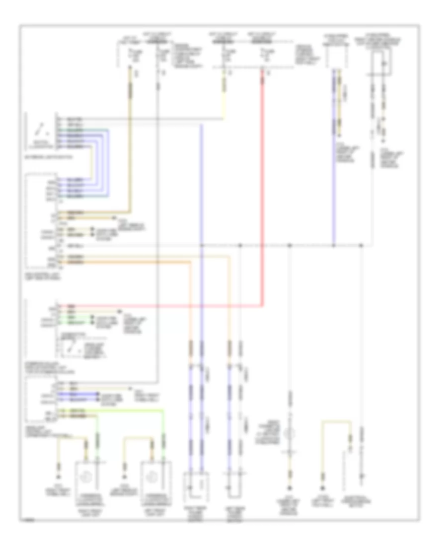
EXTERIOR LIGHTS
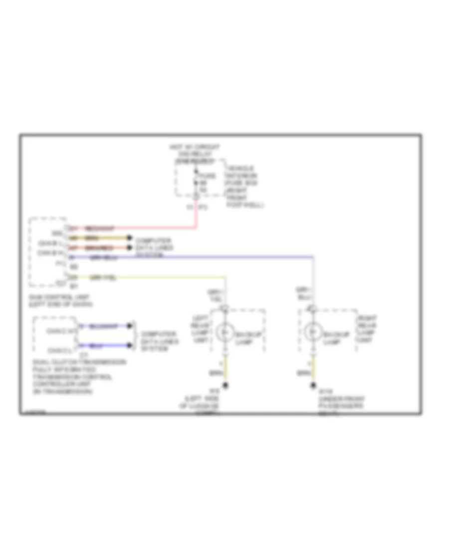
Backup Lamps Wiring Diagram for Mercedes-Benz CLA250 4Matic 2014
List of elements for Backup Lamps Wiring Diagram for Mercedes-Benz CLA250 4Matic 2014:
- (+)
- 30g
- Backup lamp
- Can b h
- Can b l
- Can c h
- Can c l
- Computer data lines system
- Dual clutch transmission fully integrated transmission control controller unit (in transmission)
- Fuse 5a
- Hot w/ circuit 30g relay energized
- Left rear lamp unit
- Right rear lamp unit
- Sam control unit (left end of dash)
- Vehicle interior fuse box (right front footwell)
- W19 (under front passenger's seat)
- W6 (left side of luggage compt)
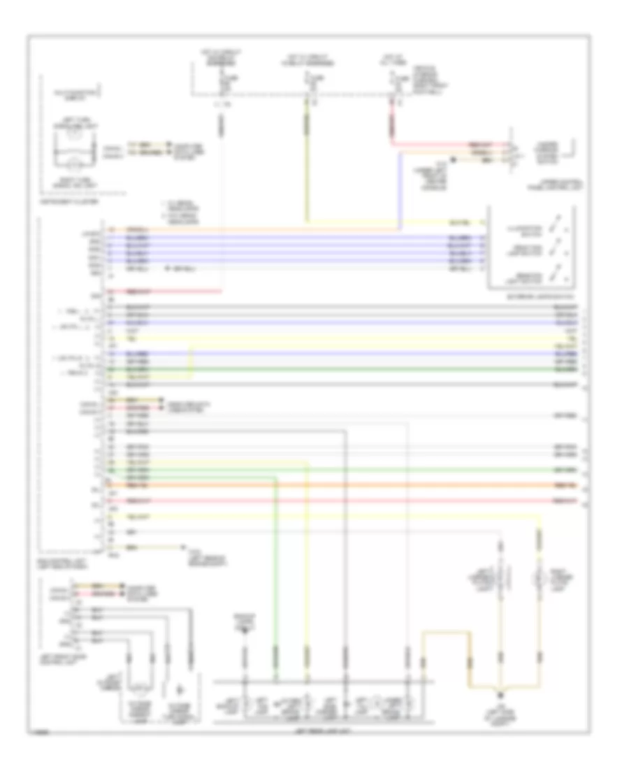
Exterior Lamps Wiring Diagram (1 of 3) for Mercedes-Benz CLA250 4Matic 2014
List of elements for Exterior Lamps Wiring Diagram (1 of 3) for Mercedes-Benz CLA250 4Matic 2014:
- (+)
- 30g
- 30l
- 58d
- Backup lamps circuit
- Can b h
- Can b l
- Computer data lines system
- Exterior lights switch
- Fra l
- Fra r
- Front fog lamp switch
- Fuse 5a
- Gnd
- Hazard warning system switch
- Headlamps
- Hot at all times
- Hot w/ circuit 15 relay energized
- Hot w/ circuit 30g relay energized
- Illumination switch
- Inner left brake lamp
- Instrument cluster
- Left backup lamp
- Left fog lamp
- Left front door control unit
- Left license plate lamp
- Left outside mirror
- Left rear lamp unit
- Left side- marker lamp
- Left tail lamp
- Left turn signal ind light
- Lin 1
- Lin b15
- Multi-function display
- Outer left brake lamp
- Outside mirror ambient lamp
- Outside mirror turn signal lamp
- Pltfl l
- Pltfl r
- Pw2
- Rear fog light switch
- Right license plate lamp
- Right turn signal ind light
- Sam control unit (left end of dash)
- Sig1
- Sig2
- Sig3
- Uh1
- Uh2
- Upltfl l
- Upltfl r
- Upper control panel control unit
- Vehicle interior fuse box (right front footwell)
- W/ xenon
- W/o xenon headlamps
- W12 (under left front of center console)
- W3/2 (left rear of engine compt)
- W6 (left side of luggage compt)
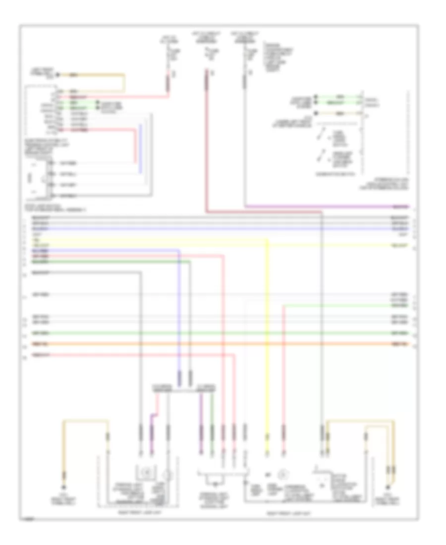
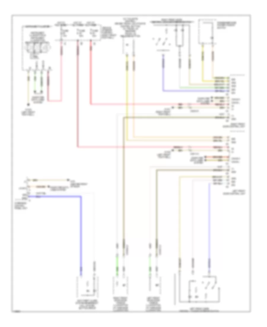
Exterior Lamps Wiring Diagram (2 of 3) for Mercedes-Benz CLA250 4Matic 2014
List of elements for Exterior Lamps Wiring Diagram (2 of 3) for Mercedes-Benz CLA250 4Matic 2014:
- (+) 12
- (left front wheelwell) w70
- Active curve illumination actuator motor (w/ intelligent light system)
- Bls h
- Bls l
- Can e h
- Can e l
- Combination switch
- Computer data lines system
- Cornering illumination (w/ intelligent light system)
- Electronic stability program control unit (left front of engine compt)
- Engine compartment fuse & relay module (left side engine compt)
- Fuse 40a
- Fuse 5a
- Gnd
- Headlamp flasher/ high beam switch
- Hot at all times
- Hot w/ circuit 15 relay energized
- Parking light, standing light & daytime running light
- Parking light, standing light, high beam & daytime running light
- Right front lamp unit
- S12
- Side- marker lamp
- Steering column module control unit (top of steering column)
- Stop lamp switch (top of brake pedal assembly)
- Turn signal lamp
- Turn signal lamps switch
- Turn signal light & side marker light
- W/ xenon headlamp
- W/o xenon headlamp
- W12 (under left front of center console)
- W3/1 (right front wheelwell)
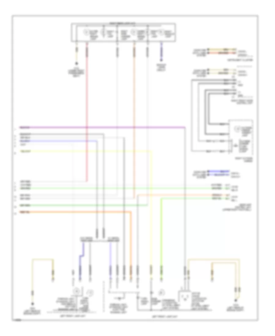
Exterior Lamps Wiring Diagram (3 of 3) for Mercedes-Benz CLA250 4Matic 2014
List of elements for Exterior Lamps Wiring Diagram (3 of 3) for Mercedes-Benz CLA250 4Matic 2014:
- (+)
- Abl l
- Abl r
- Active curve illumination actuator motor (w/ intelligent light system)
- Backup lamps circuit
- Can b h
- Can b l
- Can g h
- Can g l
- Computer data lines system
- Cornering illumination (w/ intelligent light system)
- Gnd
- Headlamp control unit (upper right footwell)
- Inner right brake lamp
- Instrument cluster
- Left front lamp unit
- Lin g1
- Lin g2
- Outer right brake lamp
- Outside mirror ambient lamp
- Outside mirror turn signal lamp
- Parking light, standing light & daytime running light
- Parking light, standing light, high beam & daytime running light
- Right backup lamp
- Right fog lamp
- Right front door control unit
- Right outside mirror
- Right rear lamp unit
- Right side- marker lamp
- Right tail lamp
- Side- marker lamp
- Turn signal lamp
- Turn signal light & side marker light
- W/ xenon headlamp
- W/o xenon headlamp
- W19 (under front passenger's seat)
- W3/2 (left rear of engine compt)
Trailer Light Wiring Diagram, Early Production for Mercedes-Benz CLA250 4Matic 2014
List of elements for Trailer Light Wiring Diagram, Early Production for Mercedes-Benz CLA250 4Matic 2014:
- (+)
- Ah bl
- Ah fra l
- Ah fra r
- Ah nsl
- Ah rfl
- Ah sl l
- Ah sl r
- Ahk io
- Ahk nio
- Can b h
- Can b l
- Computer data lines system
- Fuse 15a
- Fuse 20a
- Fuse 25a
- Fuse 5a
- Gnd
- Hot at all times
- Hot w/ circuit 15 relay energized
- Sam control unit (left end of dash)
- Trailer hitch release switch
- Trailer recognition control unit
- Trailer socket
- Vehicle interior fuse box (right front footwell)
- W6 (left side of luggage compt)
- W7 (right side of luggage compt)
- X52-c1
Trailer Light Wiring Diagram, Late Production for Mercedes-Benz CLA250 4Matic 2014
List of elements for Trailer Light Wiring Diagram, Late Production for Mercedes-Benz CLA250 4Matic 2014:
- (+)
- (right side of luggage compt) w7
- 30g
- Ah bl
- Ah fra l
- Ah fra r
- Ah nsl
- Ah rfl
- Ah sl l
- Ah sl r
- Ahk i o
- Ahk n i o
- Can b h
- Can b l
- Computer data lines system
- Fuse 15a
- Fuse 20a
- Fuse 25a
- Fuse 5a
- Gnd
- Hot at all times
- Hot w/ circuit 15 relay energized
- Sam control unit (left end of dash)
- Trailer hitch release switch
- Trailer recognition control unit
- Trailer socket
- Vehicle interior fuse box (right front footwell)
- W7 (right side of luggage compt)
- X52-c1
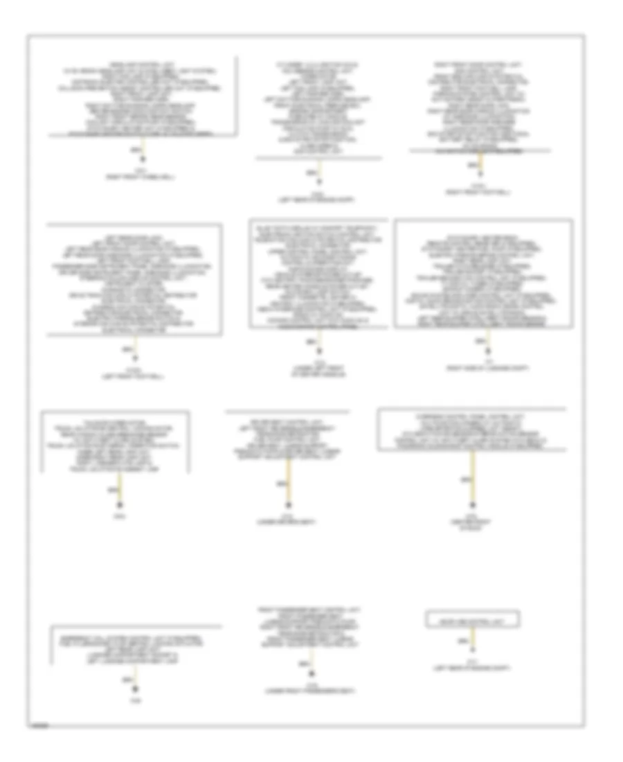
GROUND DISTRIBUTION
Ground Distribution Wiring Diagram for Mercedes-Benz CLA250 4Matic 2014
List of elements for Ground Distribution Wiring Diagram for Mercedes-Benz CLA250 4Matic 2014:
- Cylinder 1,2,3,4 ignition coils, nox sensor control unit, wiper motor, left front lamp unit, left fog lamp (if equipped), left fanfare horn, left daytime running lamps headlamp, front electrical prefuse box, engine compartment fuse & relay module, transmission oil cooling coolant circulation pump (w/ dual clutch transmission & eco start/stop function), alarm siren & sam control unit
- Driver seat control unit, left front reversible emergency tensioning retractor, fuel pump control unit, driver seat lumbar support pneumatic pump & driver seat lumbar support adjustment control unit
- Emergency call system control unit (if equipped), fuel filler/socket flap central locking actuator, left rear lamp unit, luggage compartment socket & left luggage compartment lamp
- Front passenger seat control unit, front passenger seat lumbar support pneumatic pump, right front reversible emergency tensioning retractor & front passenger seat lumbar support adjustment control unit
- Headlamp control unit (w/ bi xenon headlamp unit & intelligent light system), right fog lamp (if equipped), distronic electric controller unit (if equipped), collision prevention assist controller unit (if equipped), right front lamp unit, right fanfare horn, right daytime running lamps headlamp, center engine hood contact switch, right front brake wear sensor, coolant circulation pump (if equipped), stationary heater unit (if equipped) & stationary heater switch over valve (if equipped)
- Left rear door lock, left front door control unit, left rear door handle illumination (if equipped), left rear door ambiance illumination (if equipped), left front footwell lamp, passenger side instrument panel ambiance illumination, driver side instrument panel ambiance illumination, steering column module control unit, instrument cluster, diagnostic connector, drive train can (can c) potential distributor electrical connector, chassis can (can e) potential distributor electrical connector, electric parking brake switch & interior can (can b) potential distributor electrical connector
- Me sfi (me) control unit
- Overhead control panel control unit, multifunction camera (w/ automatic lane detection & speed limit assist), ata (edw)/towing sensor/interior motion sensor control unit (w/ anti-theft alarm system (ata (edw)) & panoramic sliding roof control module (if equipped)
- Right front door control unit, sam control unit, front end can (can g) potential distributor electrical connector, right front footwell lamp, parking system control unit (w/ active park assist & parktronic), right rear door lock, right rear door handle illumination (w/ ambiance illumination), right rear door ambiance illumination (if equipped), eco start/stop function additional battery relay (if equipped), ac housing & navigation module (if equipped)
- Stationary heater radio remote control receiver (if equipped), stationary heater fuel pump (if equipped), electric parking brake control unit, right rear lamp unit, trailer hitch release (if equipped), trailer socket (if equipped), trailer recognition control unit (if equipped), tv digital tuner (if equipped), backup camera (if equipped), sound system amplifier control unit (if equipped), digital audio broadcasting control unit (if equipped), satellite digital audio radio (sdar) control unit (w/ sirius satellite radio), left rear bumper intelligent radar sensor & right rear bumper intelligent radar sensor
- Tailgate wiper motor, trunk lid/liftgate central locking motor, rear window glass breakage sensor (w/ anti-theft alarm system), trunk lid/liftgate external operation switch, inner left rear lamp unit, inner right rear lamp unit, right license plate lamp & trunk lid/liftgate ambient lamp
- W11 (left rear of engine compt)
- W12 (under left front of center console)
- W15/1 (right front footwell)
- W15/2 (left front footwell)
- W18 (under driver's seat)
- W19 (under front passenger's seat)
- W3/1 (right front wheelwell)
- W3/2 (left rear of engine compt)
- W48
- W7 (right side of luggage compt)
- W78 (center front of roof)
- W8/4
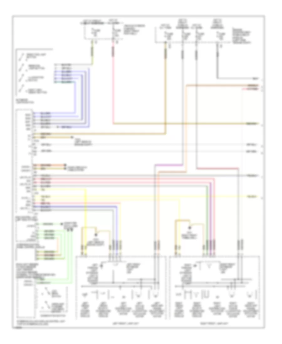
HEADLIGHTS
Headlights Wiring Diagram (1 of 2) for Mercedes-Benz CLA250 4Matic 2014
List of elements for Headlights Wiring Diagram (1 of 2) for Mercedes-Benz CLA250 4Matic 2014:
- (+)
- (left rear of engine compt)
- 30g
- 58d
- Can b h
- Can b l
- Can e h
- Can e l
- Combination switch
- Computer data lines system
- Engine compartment fuse & relay module (left side engine compt)
- Exterior lights switch
- Front fog lamp button
- Fuse 15a
- Fuse 30a
- Fuse 40a
- Fuse 5a
- Gnd
- Headlamp flasher/ high beam switch
- Hot at all times
- Hot w/ circuit 15 relay energized
- Illumination switch
- Left active curve illumination actuator motor
- Left front exterior light led
- Left front lamp unit
- Left headlamp range adjustment actuator motor
- Left light distribution actuator motor
- Left parking light, standing light & daytime running light
- Left xenon bulb w/ integrated ignition module
- Lin b13
- Low beam switch
- Night view assist button
- Overhead control panel control module
- Pltfl l
- Pw2
- Rain/light sensor (w/ rain sensor) light sensor (w/o rain sensor) (integral to interior rearview mirror base assembly)
- Rear fog lamp button
- Right active curve illumination actuator motor
- Right front exterior light led
- Right front lamp unit
- Right headlamp range adjustment actuator motor
- Right light distribution actuator motor
- Right parking light, standing light & daytime running light
- Right xenon bulb w/ integrated ignition module
- S13
- Sam control unit (left end of dash)
- Sig
- Sig1
- Sig2
- Sig3
- Steering column module control unit (top of steering column)
- Uh1
- Uh2
- Upltfl l
- Upltfl r
- Vehicle interior fuse box (right front footwell)
- W3/1 (right front wheelwell)
- W3/2
- W3/2 (left rear of engine compt)
Headlights Wiring Diagram (2 of 2) for Mercedes-Benz CLA250 4Matic 2014
List of elements for Headlights Wiring Diagram (2 of 2) for Mercedes-Benz CLA250 4Matic 2014:
- (+) 5v
- (right front wheelwell) w3/1
- (under front passenger's seat) w19
- Abl l
- Abl r
- Can b h
- Can b l
- Can e h
- Can e l
- Can g h
- Can g l
- Computer data lines system
- Electric parking brake control unit (center rear of luggage compt)
- Electric parking brake switch
- Front axle level sensor (bi-xenon headlamp) (in front right wheelwell)
- Front fog lamp indicator lamp
- Gnd
- Headlamp control unit (upper right footwell)
- High beam indicator lamp
- Inner left rear lamp unit
- Inner right rear lamp unit
- Instrument cluster
- Interior lights system
- Left fog lamp
- Left rear fog lamp
- Lin g1
- Lin g2
- Low beam indicator lamp
- Rear axle level sensor (in rear right wheelwell)
- Rear fog lamp indicator lamp
- Right fog lamp
- Right rear fog lamp
- Sig
- Sw 1
- Sw 3
- Sw 4
- Sw 6
- W15/2 (left front footwell)
- W3/1 (right front wheelwell)
- W3/2 (left rear of engine compt)
- W6 (left side of luggage compt)
- W7/1 (right rear of luggage compt)
- X25/14-c2
HORN
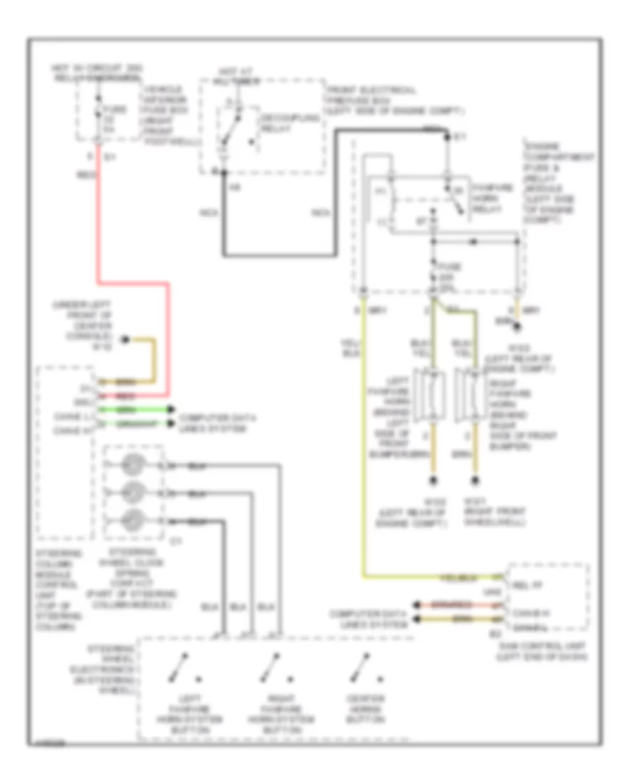
Horn Wiring Diagram for Mercedes-Benz CLA250 4Matic 2014
List of elements for Horn Wiring Diagram for Mercedes-Benz CLA250 4Matic 2014:
- (+)
- (-)
- (under left front of center console) w12
- 30g
- Button
- Can-b h
- Can-b l
- Can-e h
- Can-e l
- Center horns button
- Computer data lines system
- Decoupling relay
- Engine compartment fuse & relay module (left side of engine compt)
- Fanfare horn relay
- Front electrical prefuse box (left side of engine compt)
- Fuse 15a
- Fuse 5a
- Hot at all times
- Hot w/ circuit 30g relay energized
- Left fanfare horn (behind left side of front bumper)
- Left fanfare horn system
- Mr1
- Nca
- Red
- Rel ff
- Right fanfare horn (behind right side of front bumper)
- Right fanfare horn system
- Sam control unit (left end of dash)
- Steering column module control unit (top of steering column)
- Steering wheel clock spring contact (part of steering column module)
- Steering wheel electronics (in steering wheel)
- Uh2
- Vehicle interior fuse box (right front footwell)
- W3/1 (right front wheelwell)
- W3/2 (left rear of engine compt)
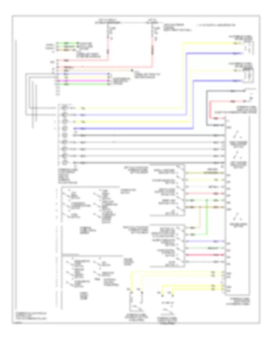
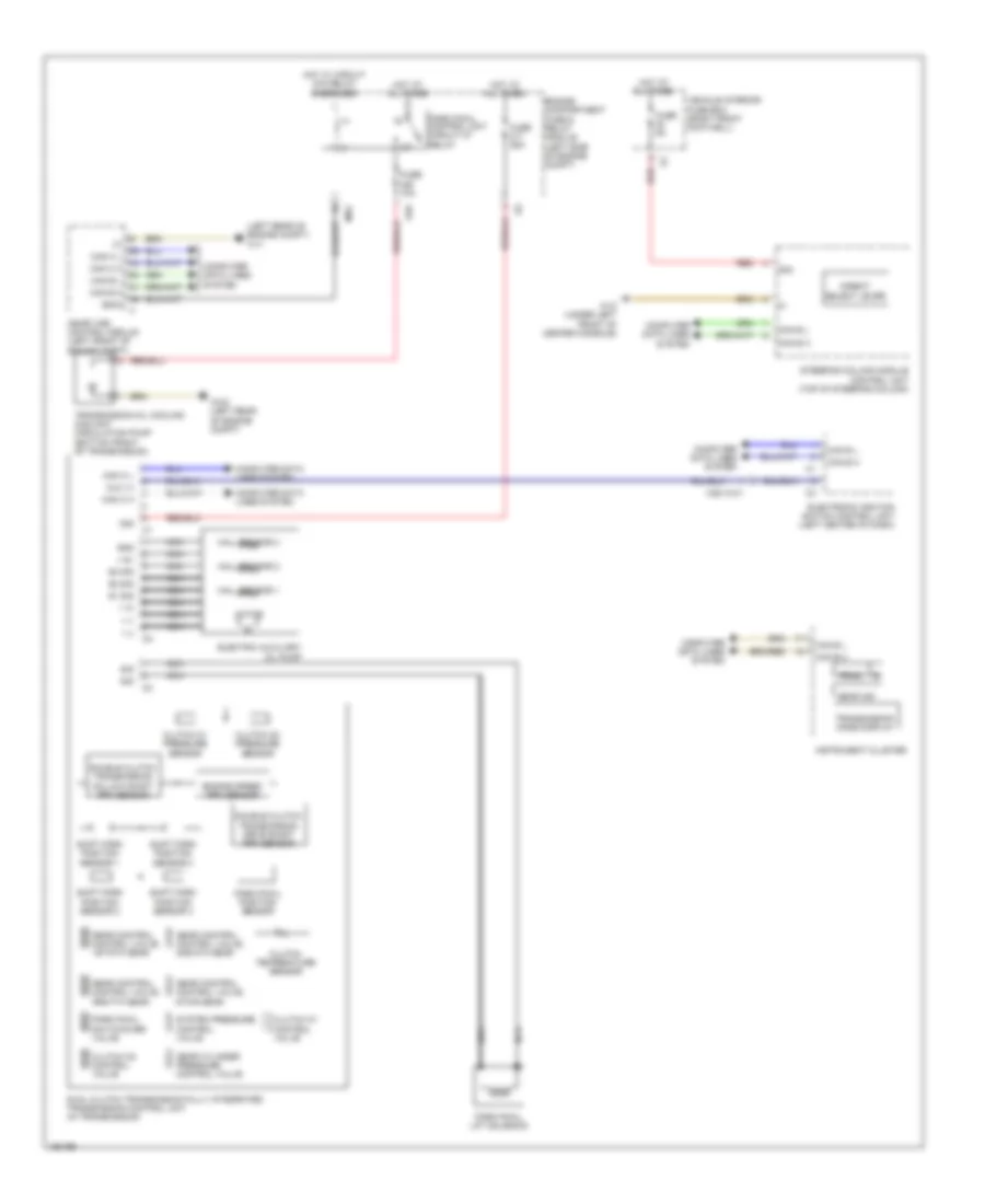
INSTRUMENT CLUSTER
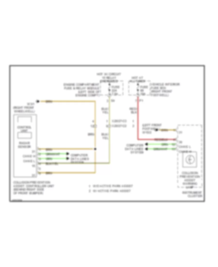
Collision Avoidance Wiring Diagram for Mercedes-Benz CLA250 4Matic 2014
List of elements for Collision Avoidance Wiring Diagram for Mercedes-Benz CLA250 4Matic 2014:
- (left front footwell) w15/2
- Can e h
- Can e l
- Collision prevention assist controller unit (behind right side of front bumper)
- Collision prevention assist warning lamp
- Computer data lines system
- Control unit
- Engine compartment fuse & relay module (left side of engine compt)
- Fuse 10a
- Fuse 7.5a
- Hot at all times
- Hot w/ circuit 15 relay energized
- Instrument cluster
- Radar sensor
- Vehicle interior fuse box (right front footwell)
- W/ active park assist
- W/o active park assist
- W3/1 (right front wheelwell)
- X26/27-c2
- X26/27-c3
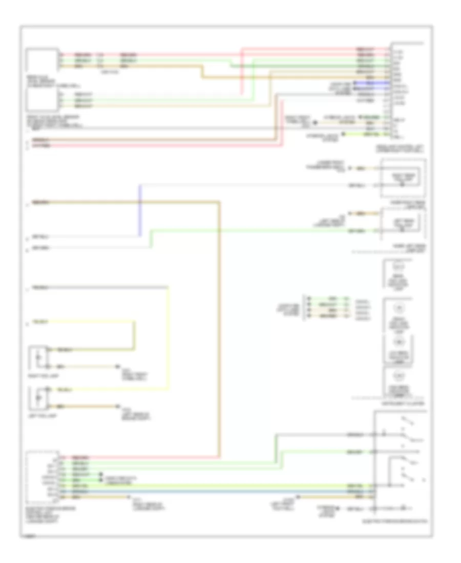
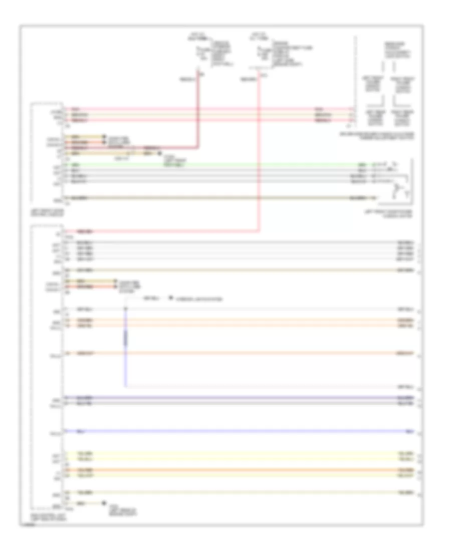
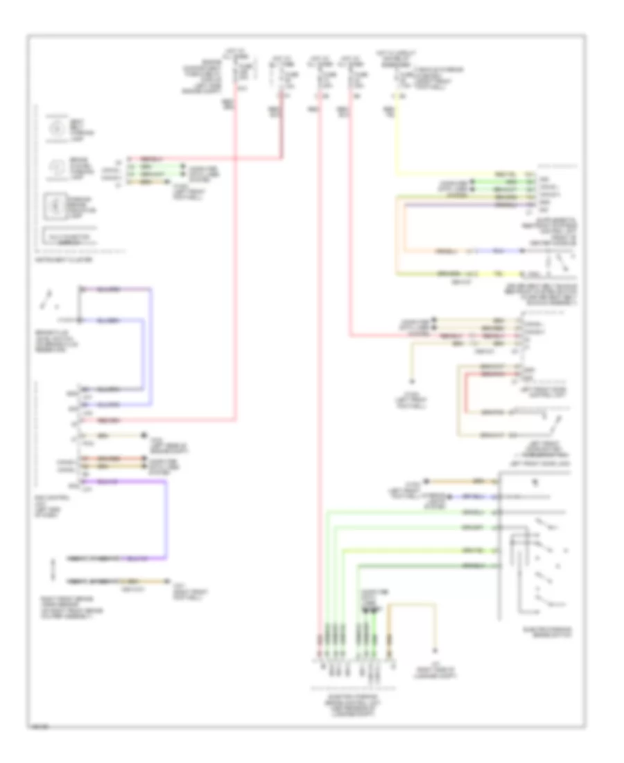
Instrument Cluster Wiring Diagram (1 of 2) for Mercedes-Benz CLA250 4Matic 2014
List of elements for Instrument Cluster Wiring Diagram (1 of 2) for Mercedes-Benz CLA250 4Matic 2014:
- (center rear of luggage compt) electric parking brake control unit
- (dual clutch transmission)
- Anti-lock brake system indicator lamp
- Brake fluid level switch (on brake fluid reservoir)
- Brake system warning lamp
- Can b h
- Can b l
- Can e h
- Can e l
- Collision prevention assist warning lamp (w/ collision warning system) distronic warning lamp (w/ distronic plus)
- Computer data lines system
- Coolant level switch (in engine coolant reservoir)
- Coolant temperature gauge
- Coolant temperature warning lamp
- Electronic stability program warning lamp
- Engine diagnosis indicator lamp
- Esp/asr off warning lamp
- Front fog lamp indicator lamp
- Fuel level indicator gauge
- Fuel reserve indicator lamp
- Fuse 10a
- Fuse 30a
- Fuse 5a
- Gear indicator (prnd)
- Gnd
- High beam indicator lamp
- Hot at all times
- Instrument cluster
- Instrument illumination
- Instrument illumination brightness control
- Left turn signal ind lamp
- Lin 1
- Lines system computer data
- Low beam indicator lamp
- Multi-function display
- Nca
- Outside temperature sensor (behind left side of front bumper)
- Parking brake indicator lamp
- Pw2
- Rear fog lamp indicator lamp
- Red
- Right turn signal ind lamp
- Sam control unit (left front of dash)
- Seat belt warning lamp
- Sig
- Speedometer
- Standing lamps indicator lamp
- Sw 1
- Sw 3
- Sw 4
- Sw 6
- Tachometer
- Tire pressure monitor warning lamp (if equipped)
- Transmission mode display (s)
- Uh1
- Uh2
- Vehicle interior fuse box (right front footwell)
- W15/2 (left front footwell)
- W3/2 (left rear of engine compt)
- W7 (right side of luggage compt)
- X18/3-c1
- X36/2-c1
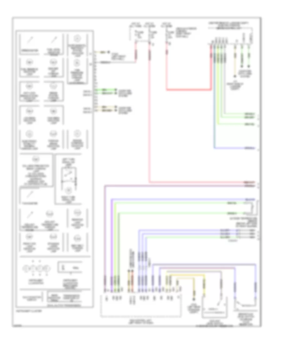
Instrument Cluster Wiring Diagram (2 of 2) for Mercedes-Benz CLA250 4Matic 2014
List of elements for Instrument Cluster Wiring Diagram (2 of 2) for Mercedes-Benz CLA250 4Matic 2014:
- Ata (edw) function indicator (if equipped)
- Automatic child seat recognition air bag off indicator lamp
- Automatic transmission mode button
- Can e h
- Can e l
- Computer data lines system
- Driver seat belt buckle restraint system switch (in driver seat belt buckle assembly)
- Eco start/ stop function button (if equipped)
- Electric parking brake switch
- Gnd
- Hazard warning system button
- Interior lights system
- Left front heated seat button (if equipped)
- Left fuel tank fuel level indicator fill level sensor (in fuel tank)
- Lin 1
- Nca
- Parking system button (if equipped)
- Right front brake wear sensor (on right front brake caliper assembly)
- Right front heated seat button (if equipped)
- Right fuel tank fuel level indicator fill level sensor (in fuel tank)
- Sig
- Stationary heater button (if equipped)
- Upper control panel control unit
- W12 (under left front of center console)
- W3/1 (right front wheelwell)
- X55/3-c1
- X88/12-c1
Overhead Console Wiring Diagram for Mercedes-Benz CLA250 4Matic 2014
List of elements for Overhead Console Wiring Diagram for Mercedes-Benz CLA250 4Matic 2014:
- (+)
- (w/ exterior lights & vision package)
- (w/ mirror package)
- 30g
- 58d
- Ambient lamp
- Door locks & anti-theft systems
- Forward automatic dimming mirror light sensor
- Front dome lamp switch
- Fuse 10a
- Garage door opener (if equipped)
- Garage door opener button 1
- Garage door opener button 2
- Garage door opener button 3
- Garage door opener indicator lamp
- Gnd
- Hot at all times
- Inside rearview mirror
- Inside rearview mirror dimming
- Interior lamp automatic function switch
- Interior lights system
- Interior temperature sensor w/ integrated fan
- Left front reading lamp switch
- Left interior lamp
- Left mounting console incident illumination
- Lin b13
- Overhead control panel control unit
- Panoramic sliding roof switch (if equipped)
- Rain/light sensor (w/ rain sensor) light sensor (w/o rain sensor) (integral to interior rearview mirror base assembly)
- Rear dome lamp switch
- Rearward automatic dimming mirror light sensor
- Red
- Right front reading lamp switch
- Right interior lamp
- Right mounting console incident illumination
- Sam control unit (left end of dash)
- Sig
- Vehicle interior fuse box (right front footwell)
- Vehicle interior humidity & temperature sensor (in overhead console)
- W78 (center front of roof)
INTERIOR LIGHTS
Courtesy Lamps Wiring Diagram (1 of 4) for Mercedes-Benz CLA250 4Matic 2014
List of elements for Courtesy Lamps Wiring Diagram (1 of 4) for Mercedes-Benz CLA250 4Matic 2014:
- (+)
- (+) bu
- (+) rd
- (+) ye
- Can-b h
- Can-b l
- Computer data lines system
- Driver-side instrument panel ambiance illumination
- Engine compartment fuse & relay module (left side engine compt)
- Front passenger seat ambiance illumination
- Front passenger seat control module (under front passenger seat)
- Front passenger side bag squib (outer edge of front passenger seat back)
- Fuse 40a
- Gnd
- Hot at all times
- Left front footwell lamp
- Left rear seat ambiance illumination
- Passenger-side instrument panel ambiance illumination
- Pw2
- Right front footwell lamp
- Right rear footwell lamp
- Right rear seat ambiance illumination
- S13
- Sam control unit (left end of dash)
- Sig
- Trunk lid/liftgate ambient lamp (exterior light & vision package)
- W/ ambiance illumination
- W/ seat ambiance illumination
- W/o ambiance illumination
- W/o seat ambiance illumination
- W12 (under left front of center console)
- W15/1 (right front footwell)
- W15/2 (left front footwell)
- W18 (under driver's seat)
- W19 (under front passenger's seat)
- W3/2 (left rear of engine compt)
- W8/4
- X55/3-c1
Courtesy Lamps Wiring Diagram (2 of 4) for Mercedes-Benz CLA250 4Matic 2014
List of elements for Courtesy Lamps Wiring Diagram (2 of 4) for Mercedes-Benz CLA250 4Matic 2014:
- (+)
- Can-b h
- Can-b l
- Computer data lines system
- Driver seat ambiance illumination
- Driver seat control unit (under driver seat)
- Driver side bag squib (outer edge of driver seat back)
- Gnd
- Left front illuminated door sill molding (if equipped)
- Left rear door ambiance illumination
- Left rear door door handle illumination
- Left rear door lock
- Left rear door rotary tumbler switch
- Left rear footwell lamp
- Nca
- Right front illuminated door sill molding (if equipped)
- Right rear door ambiance illumination
- Right rear door door handle illumination
- Right rear door lock
- Right rear door rotary tumbler switch
- W/ ambiance illumination
- W/ seat ambiance illumination
- W/o ambiance illumination
- W/o seat ambiance illumination
- W15/1 (right front footwell)
- W15/2 (left front footwell)
- W18 (under driver's seat)
- X100/3-c1
- X100/4-c1
- X35/3-c1
- X35/4-c1
- X55/3-c1
Courtesy Lamps Wiring Diagram (3 of 4) for Mercedes-Benz CLA250 4Matic 2014
List of elements for Courtesy Lamps Wiring Diagram (3 of 4) for Mercedes-Benz CLA250 4Matic 2014:
- (+)
- 58d
- Ambient lamp (exterior light & vision package)
- Can e h
- Can e l
- Computer data lines system
- Front dome lamp switch
- Fuse 10a
- Fuse 30a
- Fuse 5a
- Garage door opener
- Garage door opener indicator lamp
- Glove box lamp
- Glove box lamp switch
- Gnd
- Hot at all times
- Hot w/ circuit 15r1 relay energized
- Inside rearview mirror
- Instrument cluster
- Interior lamp automatic function switch
- Left front mirror lamp switch
- Left front reading lamp switch
- Left inside rearview mirror interior lamp (exterior light & vision package)
- Left luggage compartment lamp
- Left mounting console incident illumination
- Left sun visor mirror lamp
- Lin b13
- Overhead control panel unit
- Pnk
- Rain/light sensor (w/ rain sensor) light sensor (w/o rain sensor) (integral to interior rearview mirror base assembly)
- Rear dome lamp switch
- Red
- Right front mirror lamp switch
- Right front reading lamp switch
- Right inside rearview mirror interior lamp (exterior light & vision package)
- Right mounting console incident illumination
- Right sun visor mirror lamp
- S21
- S22
- Sun visors w/ illuminated mirrors
- Tailgate external operation switch
- Vehicle interior fuse box (right front footwell)
- W12 (under left front of center console)
- W48
- W6 (left side of luggage compt)
- W78 (center front of roof)
- X29-c1
Courtesy Lamps Wiring Diagram (4 of 4) for Mercedes-Benz CLA250 4Matic 2014
List of elements for Courtesy Lamps Wiring Diagram (4 of 4) for Mercedes-Benz CLA250 4Matic 2014:
- (+)
- (+) rd
- (+) ye
- (+)/(+) ye
- (exterior light & vision package) right front door ambiance illumination
- (exterior light & vision package) right front door exit & warning lamp
- Can b h
- Can b l
- Computer data lines system
- Gnd
- Left front door ambiance illumination
- Left front door ambiance illumination (exterior light & vision package)
- Left front door control unit
- Left front door exit & warning lamp (exterior light & vision package)
- Left front door handle illumination
- Left front door lock
- Left front door rotary tumbler switch
- Left rear reading lamp
- Left rear reading lamp switch
- Nca
- Rear ambient lamp
- Rear dome lamp
- Rear dome lamp (w/ reading lamps)
- Red
- Right front door ambiance illumination
- Right front door control unit
- Right front door handle illumination
- Right front door lock
- Right front door rotary tumbler switch
- Right rear reading lamp
- Right rear reading lamp switch
- Sig
- W/ ambiance illumination
- W/ exterior light & vision package
- W/o ambiance illumination
- W/o exterior light & vision package
- W15/1 (right front footwell)
- W15/2 (left front footwell)
- X157/6-c1
- X157/6-c2
- X157/7-c1
- X157/7-c2
- X35/1-c1
- X35/2-c1
Instrument Illumination Wiring Diagram (1 of 2) for Mercedes-Benz CLA250 4Matic 2014
List of elements for Instrument Illumination Wiring Diagram (1 of 2) for Mercedes-Benz CLA250 4Matic 2014:
- (if equipped) front center console cup holder ambiance illumination
- (if equipped) two-way radio switch
- 30g
- 58d
- Abl l
- Abl r
- Can e h
- Can e l
- Can g h
- Can g l
- Can-b h
- Can-b l
- Combination switch
- Computer data lines system
- Cornering illumination (if equipped)
- Electrical parking brake switch
- Engine compartment fuse & relay module (left side engine compt)
- Exterior lights switch
- Front cigarette lighter w/ ashtray illumination (if equipped)
- Fuse 15a
- Fuse 40a
- Fuse 5a
- Gnd
- Headlamp control unit (upper right footwell)
- Headlamp flasher/ high beam switch
- Hot at all times
- Hot w/ circuit 15 relay energized
- Hot w/ circuit 30g relay energized
- Left front lamp unit
- Left rear power window switch
- Nca
- Pw2
- Red
- Right front lamp unit
- Right rear power window switch
- S13
- Sam control unit (left end of dash)
- Sig 1
- Sig 2
- Sig 3
- Steering column module control unit (top of steering column)
- Switch illumination
- Vehicle interior fuse box (right front footwell)
- W12 (under left front of center console)
- W15/2 (left front footwell)
- W3/1 (right front wheelwell)
- W3/2 (left rear of engine compt)
- X100/4-c1
- X138/1-c1
- X138/1-c4
- X300/3-c1
- X35/3-c1
- X35/4-c1
Instrument Illumination Wiring Diagram (2 of 2) for Mercedes-Benz CLA250 4Matic 2014
List of elements for Instrument Illumination Wiring Diagram (2 of 2) for Mercedes-Benz CLA250 4Matic 2014:
- (+)
- (w/ tailgate control) driver trunk lid/liftgate control button (w/ trunk lid release) trunk lid release button
- 58d
- Anti-theft alarm system/emergency call system button group
- Can b h
- Can b l
- Can e h
- Can e l
- Computer data lines system
- Fuse 10a
- Fuse 30a
- Gnd
- Hot at all times
- Instrument cluster
- Instrument illumination & instrument illumination brightness control
- Left front door central locking interior switch
- Left front door control unit
- Left front door door handle illumination (w/ ambiance illumination)
- Lin b13
- Overhead control panel unit
- Passenger side power window switch
- Red
- Right front door central locking interior switch
- Right front door control unit
- Right front door door handle illumination (w/ ambiance illumination)
- Sig
- Vehicle interior fuse box (right front footwell)
- W15/1 (right front footwell)
- W15/2 (left front footwell)
- W78 (center front of roof)
- X157/6-c2
- X157/7-c2
- X35/1-c1
- X35/2-c1
MEMORY SYSTEMS
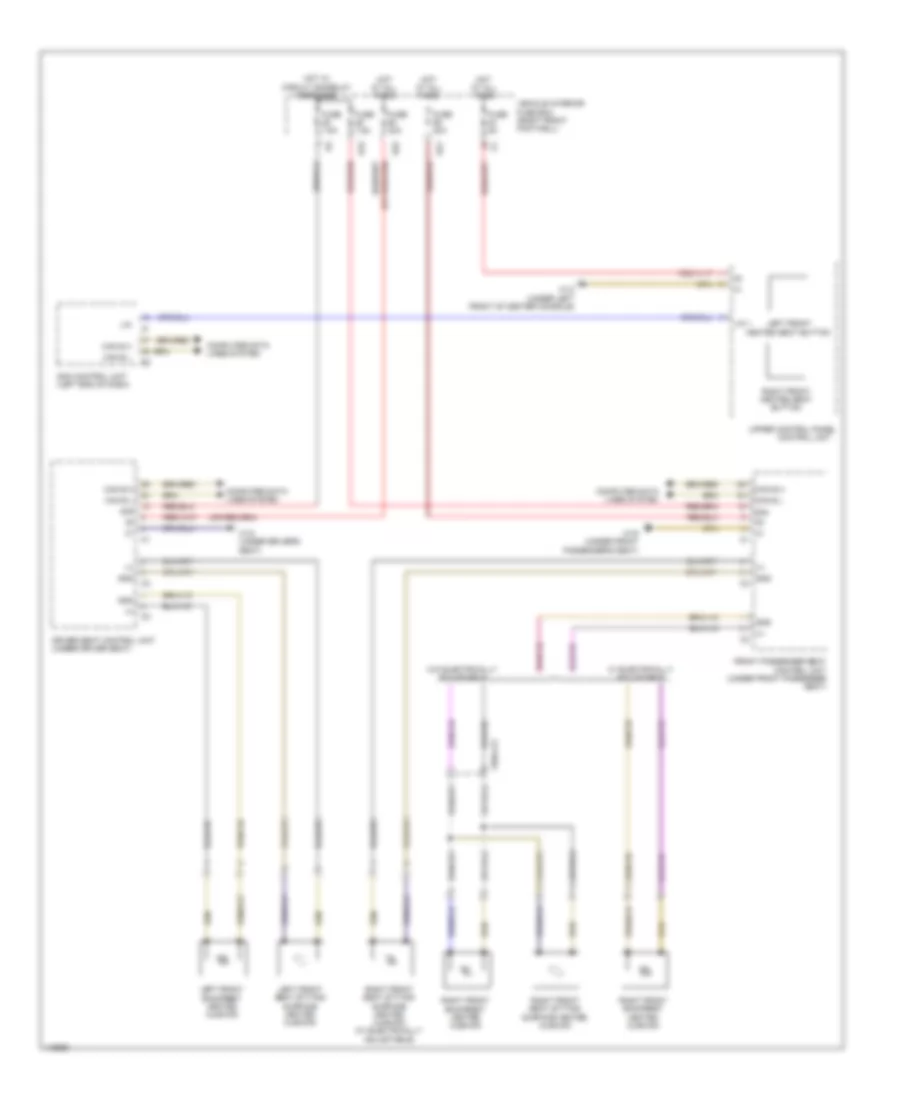
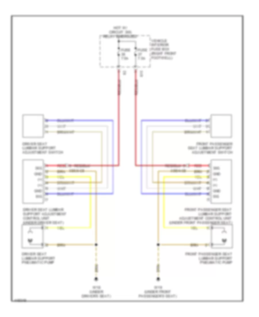
Driver"s Memory Seat Wiring Diagram (1 of 2) for Mercedes-Benz CLA250 4Matic 2014
List of elements for Driver"s Memory Seat Wiring Diagram (1 of 2) for Mercedes-Benz CLA250 4Matic 2014:
- (+)
- 30g
- Can b h
- Can b l
- Computer data lines system
- Driver seat backrest inclination adjustment motor & hall sensor
- Driver seat control unit
- Driver seat head restraint adjustment motor & hall sensor
- Driver seat lumbar support adjustment control unit (under driver seat)
- Driver seat lumbar support adjustment switch
- Driver seat lumbar support pneumatic pump
- Fuse 30a
- Fuse 7.5a
- Gnd
- Hot at all times
- Hot w/ circuit 30g relay energized
- Lin b12
- Mot
- Red
- S22
- Seats system
- Sig
- Vehicle interior fuse box (right front footwell)
- W18 (under driver's seat)
- X55/4-c5
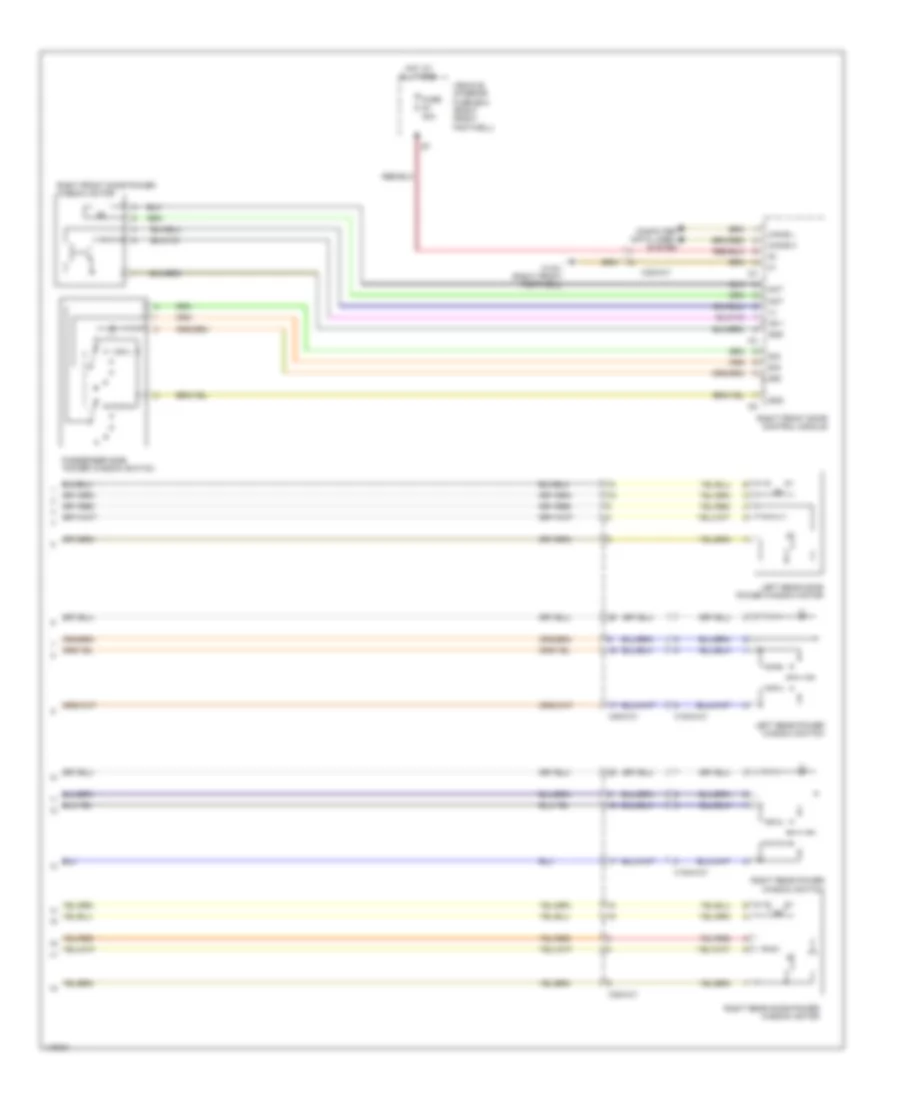
Driver"s Memory Seat Wiring Diagram (2 of 2) for Mercedes-Benz CLA250 4Matic 2014
List of elements for Driver"s Memory Seat Wiring Diagram (2 of 2) for Mercedes-Benz CLA250 4Matic 2014:
- (+)
- Can b h
- Can b l
- Computer data lines system
- Driver seat control unit
- Driver seat fore/aft adjustment motor & hall sensor
- Driver seat height adjustment motor & hall sensor
- Driver seat inclination adjustment motor & hall sensor
- Fuse 30a
- Gnd
- Hot at all times
- Interior lights system
- Left front door control unit
- Left front seat adjustment switch group
- Lin b5
- Mot
- Sam control unit (left end of dash)
- Seats system
- Sig
- Vehicle interior prefuse box (right front footwell)
- W15/2 (left front footwell)
- X35/1-c1
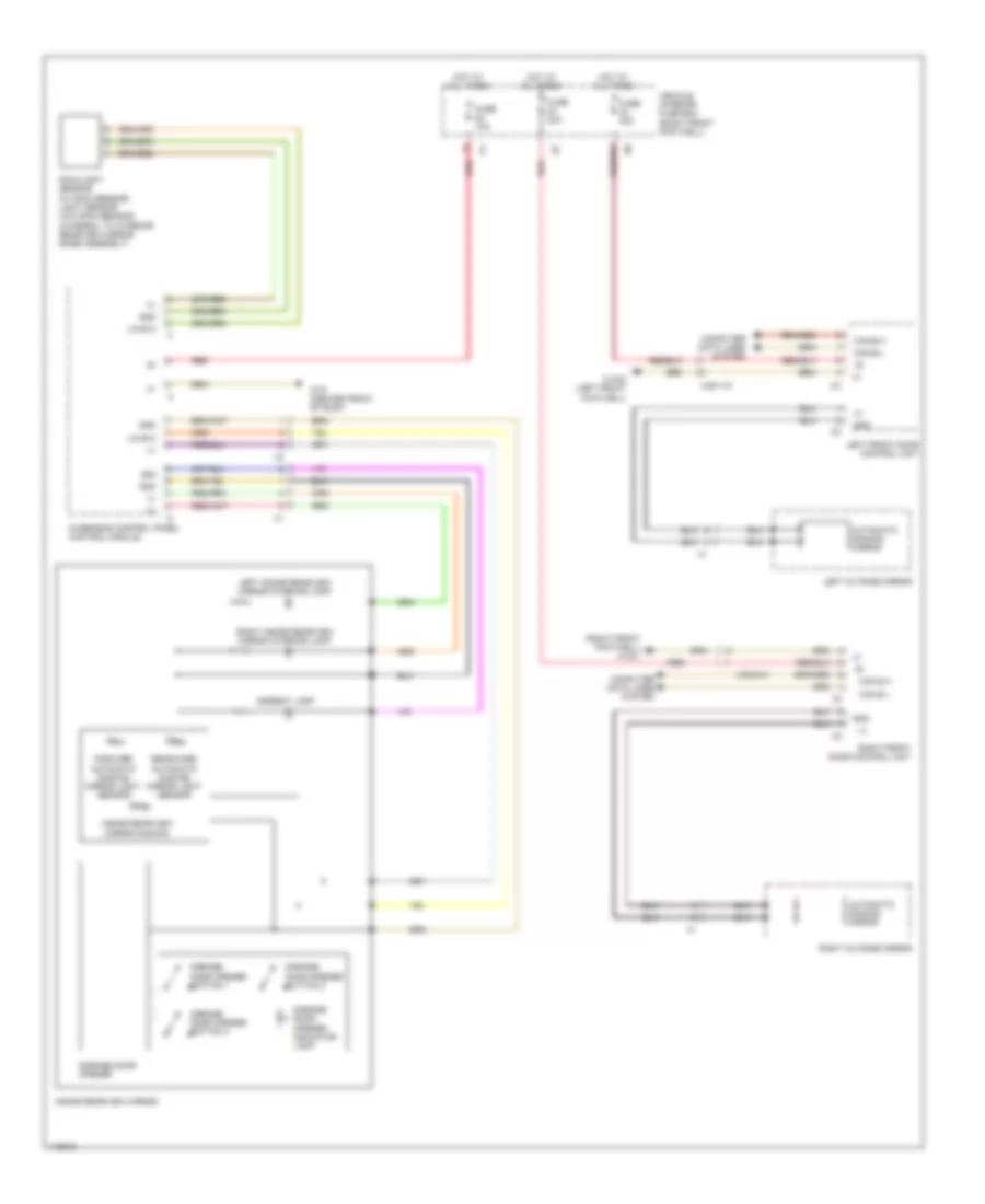
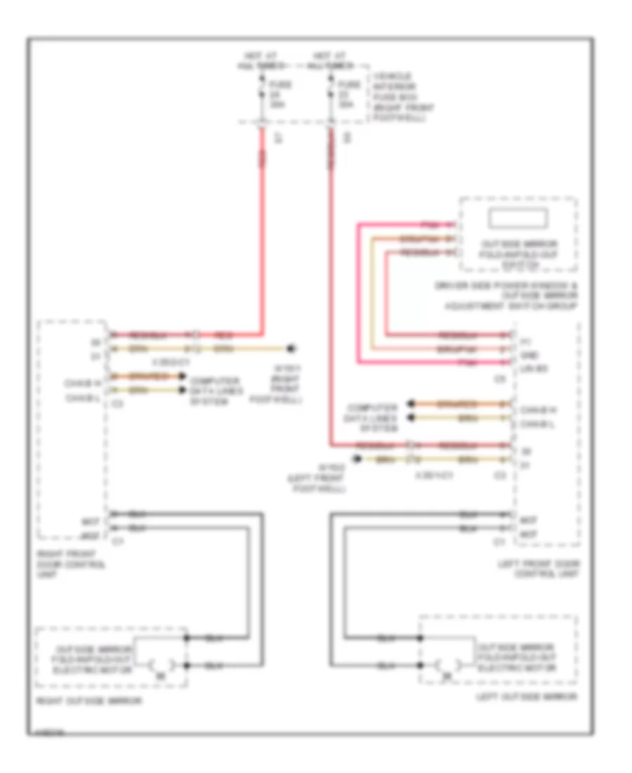
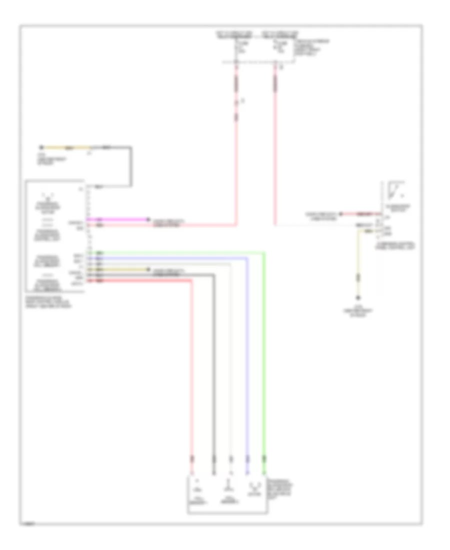
Memory Mirrors Wiring Diagram (1 of 2) for Mercedes-Benz CLA250 4Matic 2014
List of elements for Memory Mirrors Wiring Diagram (1 of 2) for Mercedes-Benz CLA250 4Matic 2014:
- (+)
- (right front footwell) w15/1
- Automatic dimming mirror
- Can b h
- Can b l
- Computer data lines system
- Driver side power window & outside mirror adjustment switch
- Fuse 30a
- Gnd
- Horizontal inclination adjustment actuator motor
- Horizontal inclination adjustment potentiometer
- Hot at all times
- Left outside mirror adjustment switch
- Lin b6
- Mirror heater
- Mot
- Outside mirror adjustment switch
- Outside mirror fold-in/fold-out electric motor
- Outside mirror fold-in/fold-out switch
- Pnk
- Red
- Right blind spot assist readiness & warning indicator
- Right front door control unit
- Right front seat adjustment switch group
- Right outside mirror
- Right outside mirror adjustment switch
- Right outside mirror ambient lamp
- Right outside mirror turn signal lamp
- Sig
- Ta b(+)
- Ta w(+)
- Vehicle interior fuse box (right front footwell)
- Vertical inclination adjustment actuator motor
- Vertical inclination adjustment potentiometer
- X35/2-c1
Memory Mirrors Wiring Diagram (2 of 2) for Mercedes-Benz CLA250 4Matic 2014
List of elements for Memory Mirrors Wiring Diagram (2 of 2) for Mercedes-Benz CLA250 4Matic 2014:
- (+)
- Automatic dimming mirror
- B(+)
- Can-b h
- Can-b l
- Computer data lines system
- Fuse 30a
- Gnd
- Horizontal inclination adjustment actuator motor
- Horizontal inclination adjustment potentiometer
- Hot at all times
- Left blind spot assist readiness & warning indicator
- Left front door control module
- Left front seat adjustment switch group
- Left outside mirror
- Left outside mirror ambient lamp
- Left outside mirror turn signal lamp
- Lin b5
- Mirror heater
- Mot
- Outside mirror fold-in/fold-out electric motor
- Pnk
- Sig
- Ta w(+)
- Vehicle interior fuse box (right front footwell)
- Vertical inclination adjustment actuator motor
- Vertical inclination adjustment potentiometer
- W15/2 (left front footwell)
- X35/1-c1
Passenger"s Memory Seat Wiring Diagram (1 of 2) for Mercedes-Benz CLA250 4Matic 2014
List of elements for Passenger"s Memory Seat Wiring Diagram (1 of 2) for Mercedes-Benz CLA250 4Matic 2014:
- (+)
- (under front passenger's seat) w19
- 30g
- Can b h
- Can b l
- Computer data lines system
- Front passenger backrest seat inclination adjustment motor & hall sensor
- Front passenger seat control unit
- Front passenger seat head restraint adjustment motor & hall sensor
- Front passenger seat lumbar support adjustment control unit (under front passenger seat)
- Front passenger seat lumbar support adjustment switch
- Front passenger seat lumbar support pneumatic pump
- Fuse 30a
- Fuse 7.5a
- Gnd
- Hot at all times
- Hot w/ circuit 30g relay energized
- Lin b12
- Mot
- Red
- S15
- S21
- Seats system
- Sig
- Vehicle interior fuse box (right front footwell)
- W19 (under front passenger's seat)
- X35/4-c5
- X55/4-c5
Passenger"s Memory Seat Wiring Diagram (2 of 2) for Mercedes-Benz CLA250 4Matic 2014
List of elements for Passenger"s Memory Seat Wiring Diagram (2 of 2) for Mercedes-Benz CLA250 4Matic 2014:
- (+)
- Can b h
- Can b l
- Computer data lines system
- Front passenger seat control unit
- Front passenger seat fore/aft adjustment motor & hall sensor
- Front passenger seat height adjustment motor & hall sensor
- Front passenger seat inclination adjustment motor & hall sensor
- Fuse 30a
- Gnd
- Hot at all times
- Interior lights system
- Lin b5
- Mot
- Red
- Right front door control unit
- Right front seat adjustment switch group
- Sam control unit (left end of dash)
- Seats system
- Sig
- Vehicle interior prefuse box (right front footwell)
- W15/1 (right front footwell)
- X35/2-c1
NAVIGATION
Blind Spot Information System Wiring Diagram for Mercedes-Benz CLA250 4Matic 2014
List of elements for Blind Spot Information System Wiring Diagram for Mercedes-Benz CLA250 4Matic 2014:
- A b(+)
- A w(+)
- Can b h
- Can b l
- Can s h
- Can s l
- Computer data lines system
- Fuse 5a
- Gnd
- Hot w/ circuit 15 relay energized
- Left blind spot assist readiness & warning indicator
- Left front door control unit
- Left outside mirror
- Left rear bumper intelligent radar sensor (behind left end of rear bumper)
- Right blind spot assist readiness & warning indicator
- Right front door control unit
- Right outside mirror
- Right rear bumper intelligent radar sensor (behind right end of rear bumper)
- Sam control unit (left end of dash)
- Vehicle interior fuse box (right front footwell)
- W7 (right side of luggage compt)
- X172/2
- X172/2-c1
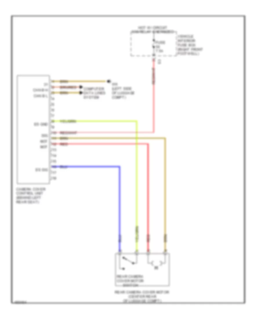
Camera Cover Control Wiring Diagram for Mercedes-Benz CLA250 4Matic 2014
List of elements for Camera Cover Control Wiring Diagram for Mercedes-Benz CLA250 4Matic 2014:
- 30g
- Camera cover control unit (behind left rear seat)
- Can b h
- Can b l
- Computer data lines system
- Es gnd
- Es sig
- Fuse 7.5a
- Hot w/ circuit 30g relay energized
- Mot
- Rear camera cover motor (center rear of luggage compt)
- Rear camera cover motor switch
- Red
- Vehicle interior fuse box (right front footwell)
- W6 (left side of luggage compt)
Emergency Call Wiring Diagram for Mercedes-Benz CLA250 4Matic 2014
List of elements for Emergency Call Wiring Diagram for Mercedes-Benz CLA250 4Matic 2014:
- (left side of luggage compt)
- (right side of luggage compt) sound system amplifier control unit
- (w/ iphone drive kit 4/4s & 5) iphone drive kit control unit
- 1a2
- A adar
- A gps
- A not
- A tel
- As (+)
- As (-)
- C sig
- Can d h
- Can d l
- Center instrument panel speaker
- Comand actuation circuit
- Comand control unit (w/o audio 20) radio (w/ audio 20)
- Computer data lines system
- Early production
- Emergency call system antenna (under right side of hat shelf)
- Emergency call system control unit (under center of hat shelf)
- Fuse 5a
- Global positioning system antenna splitter (under right side of hat shelf)
- Hot at all times
- Late production
- Mf (+)
- Mf (-)
- Multi-function antenna
- Nca
- Shield
- Tel st
- Vehicle interior fuse box (right front footwell)
- W/ navigation system
- W/ sound system amplifier
- W/o navigation system
- W/o sound system amplifier
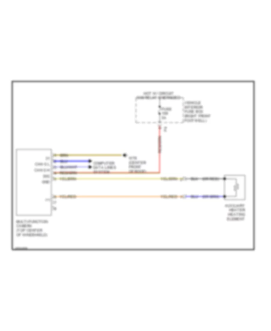
Multifunction Camera Wiring Diagram for Mercedes-Benz CLA250 4Matic 2014
List of elements for Multifunction Camera Wiring Diagram for Mercedes-Benz CLA250 4Matic 2014:
- (+)
- (or red)
- 30g
- Auxiliary heater heating element
- Can g h
- Can g l
- Computer data lines system
- Fuse 5a
- Gnd
- Hot w/ circuit 30g relay energized
- Multi-function camera (top center of windshield)
- Vehicle interior fuse box (right front footwell)
- W78 (center front of roof)
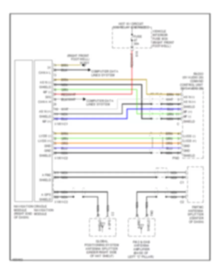
Navigation Wiring Diagram for Mercedes-Benz CLA250 4Matic 2014
List of elements for Navigation Wiring Diagram for Mercedes-Benz CLA250 4Matic 2014:
- (right front footwell) w15/1
- 30g
- A fm2
- A gps
- As n (+)
- As n (-)
- Can a h
- Can a l
- Computer data lines system
- Cradle navigation module
- Fm 2 & dab antenna amplifier (base of left "c" pillar)
- Fm/tmc antenna splitter (center of dash)
- Fm2
- Fuse 30a
- Global positioning system antenna splitter (under right side of hat shelf)
- Gnd
- Hot w/ circuit 30g relay energized
- Lvds (+)
- Lvds (-)
- Mf (+)
- Mf (-)
- Navigation module (right end of dash)
- Nca
- Pnd
- Radio (w/ audio 20) comand control unit (w/o audio 20)
- S16
- Shield
- Vehicle interior fuse box (right front footwell)
- X1/61-c1
- X1/61-c2
- X1/61-c3
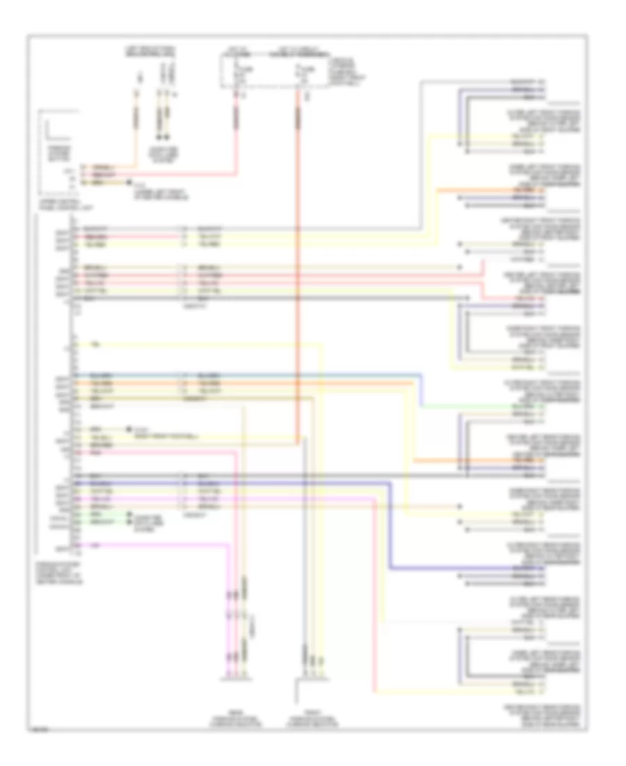
Parktronic Wiring Diagram for Mercedes-Benz CLA250 4Matic 2014
List of elements for Parktronic Wiring Diagram for Mercedes-Benz CLA250 4Matic 2014:
- (+)
- (left end of dash) sam control unit
- 30g
- Can b h
- Can b l
- Can e h
- Can e l
- Center left front parking system distance sensor (behind center left side of front bumper)
- Center left rear parking system distance sensor (behind inner left center of rear bumper)
- Center right front parking system distance sensor (behind center right side of front bumper)
- Center right rear parking system distance sensor (behind center right side of rear bumper)
- Computer data lines system
- Ddat
- Front parking system warning indicator
- Fuse 5a
- Gnd
- Hot at all times
- Hot w/ circuit 30g relay energized
- Inner left front parking system distance sensor (behind inner left side of front bumper)
- Inner left rear parking system distance sensor (behind inner left side of rear bumper)
- Inner right front parking system distance sensor (behind inner right side of front bumper)
- Inner right rear parking system distance sensor (behind inner right side of rear bumper)
- Lin 1
- Outer left front parking system distance sensor (behind outer left side of front bumper)
- Outer left rear parking system distance sensor (behind outer left side of rear bumper)
- Outer right front parking system distance sensor (behind outer right side of front bumper)
- Outer right rear parking system distance sensor (behind outer right side of rear bumper)
- Parking system button
- Parking system control unit (under front of center console)
- Pnk
- Rear parking system warning indicator
- S12
- Upper control panel control unit
- Vehicle interior fuse box (right front footwell)
- W12 (under left front of center console)
- W15/1 (right front footwell)
- X26/27-c1
- X35/28-c1
- X35/37-c1
Rear Camera Wiring Diagram for Mercedes-Benz CLA250 4Matic 2014
List of elements for Rear Camera Wiring Diagram for Mercedes-Benz CLA250 4Matic 2014:
- (center of luggage compt lid) (early production) backup camera
- (under front passenger's seat) w19
- 30g
- Backup camera (late production) (center of luggage compt lid)
- Can g h
- Can g l
- Computer data lines system
- Early production
- Fuse 5a
- Gnd
- Hot w/ circuit 30g relay energized
- Late production
- Nca
- Radio (w/ audio 20) comand control unit (w/o audio 20)
- Red
- Red/ pnk
- Red/pnk
- Rvh
- Shield
- Vds (+)
- Vds (-)
- Vehicle interior fuse box (right front footwell)
- Vid
- W7 (right side of luggage compt)
POWER DISTRIBUTION
Power Distribution Wiring Diagram (1 of 5) for Mercedes-Benz CLA250 4Matic 2014
List of elements for Power Distribution Wiring Diagram (1 of 5) for Mercedes-Benz CLA250 4Matic 2014:
- (left side of engine compt) front electrical prefuse box
- (not used)
- (right front footwell) vehicle interior fuse box
- 85a
- 85b
- 86a
- 86b
- Alternator
- Audio/ comand control panel
- Audio/ comand display
- Automatic air conditioning control & operating unit
- Battery sensor
- Circuit 30g relay
- Decoupling relay
- Driver seat control unit (w/ memory)
- Driver seat lumbar support adjustment control unit (if equipped) & driver seat control unit (w/ memory)
- Eco start/ stop function additional battery relay
- Electric parking brake control unit
- Electrical power steering control unit
- Fan motor
- Front passenger seat control unit
- Front passenger seat control unit (if equipped)
- Fuel pump control unit
- Fuse 100a
- Fuse 10a
- Fuse 125a
- Fuse 150a
- Fuse 200a
- Fuse 200a (or 250a)
- Fuse 20a
- Fuse 25a
- Fuse 300a
- Fuse 30a
- Fuse 40a
- Fuse 5a
- Fuse 7.5a
- Fuse 7.5a (or 5a)
- Fuse 70a
- Fuse 80a
- Fuse n/a
- Left front door control unit
- On board electrical system battery
- Overhead control panel control unit
- Ptc heater booster (if equipped)
- Pw2
- Pyrofuse (on battery positive (+) post)
- Red
- Right front door control unit
- S10
- S15
- S18
- S19
- S20
- S21
- S22
- S23
- S24
- S25
- S26
- Sam control unit
- Sound system amplifier control unit (if equipped)
- Starter
- Steering column module control unit
- Telematics services communication module (early production) & keyless-go control unit (if equipped)
- To engine compartment fuse & relay module (diagram 2 of 5)
- To engine compartment fuse & relay module (diagram 3 of 5)
- To fuse 110 (diagram 2 of 5)
- To fuse 26 (diagram 5 of 5)
- To fuse 47 (diagram 2 of 5)
- Trailer recognition control unit (if equipped)
- Trunk lid/lift gate control unit
- Uh1
- W10 (left side of engine compt)
- W3/2 (left rear of engine compt)
- X25/14-c1
Power Distribution Wiring Diagram (2 of 5) for Mercedes-Benz CLA250 4Matic 2014
List of elements for Power Distribution Wiring Diagram (2 of 5) for Mercedes-Benz CLA250 4Matic 2014:
- (+)
- (-)
- (diagram 1 of 5)
- (left side engine compt) engine compartment fuse & relay module
- (not used)
- (right front footwell) vehicle interior fuse box
- (w/ eco start/ stop function)
- 30z
- Ac housing
- Alarm siren (w/ anti-theft alarm system)
- All-wheel drive control unit (4matic)
- Ata (edw)/towing sensor/interior motion sensor control unit
- Camera cover control unit (w/ backup camera)
- Charging socket electrical connector (w/ emergency vehicles)
- Circuit 15 relay (unlatched)
- Circuit relay
- Diagnostic connector
- Distronic electric controller unit & collision prevention assist controller unit
- Electronic stability program control unit
- Fanfare horn relay
- Fm, am & cl (zv) antenna amplifier
- From front electrical prefuse box (diagram 1 of 5)
- From fuse 46 c
- From fuse 63 d (diagram 1 of 5)
- Fuse 10a
- Fuse 15a
- Fuse 20a
- Fuse 240a 25a
- Fuse 240b n/a
- Fuse 25a
- Fuse 30a
- Fuse 40a
- Fuse 5a
- Fuse 7.5a
- Fuse n/a
- Headlamp control unit
- Heated windshield relay
- Instrument cluster
- Iphone drive kit control unit (if equipped) & comand fan motor (if equipped)
- Left front lamp unit
- Left front lamp unit (w/ static led headlamp)
- Left front reversible emergency tensioning retractor (w/ pre- safe)
- Mobile phone electrical connector (w/ comfort telephony)
- Mr1
- Mr2
- Navigation module (if equipped) & iphone cradle control unit (reinstallation for iphone)
- Overhead control panel control unit
- Panoramic sliding roof control module (if equipped)
- Parking system control unit (w/ active park assist)
- Pw1
- Pw2
- Radio (w/ audio 20) & comand control unit (w/o audio 20)
- Red
- Red/ pnk
- Right front lamp unit
- Right front lamp unit (w/ static led headlamp)
- Right front reversible emergency tensioning retractor (w/ pre- safe)
- S12
- S13
- S14
- S16
- S17
- S27
- S28
- S29
- Sam control unit
- Starter circuit relay
- Stationary heater radio remote control receiver (if equipped)
- Stationary heater unit (if equipped)
- Telematics services communication module (late production) & emergency call system control unit
- To circuit 15r2 relay (diagram 3 of 5)
- To circuit 87 relay (diagram 3 of 5)
- To electronic ignition switch control unit (diagram 5 of 5)
- To fuse 99 (diagram 4 of 5)
- Uh2
- Upper control panel control unit
- W3/2 (left rear of engine compt)
- W7 (right side of luggage compt)
- Windshield wiper on/off relay
Power Distribution Wiring Diagram (3 of 5) for Mercedes-Benz CLA250 4Matic 2014
List of elements for Power Distribution Wiring Diagram (3 of 5) for Mercedes-Benz CLA250 4Matic 2014:
- (+)
- (-)
- (not used)
- (right front footwell) vehicle interior fuse box
- (under left front of center console) w12
- 15r2
- 87m
- Alternator, coolant thermostat heating element, boost pressure control pressure transducer, coolant pump switchover valve, divert air switchover valve, oxygen sensor downstream of catalytic converter, engine oil pump valve, partial load operation crankcase ventilation valve & full load operation vent line heater element
- Ashtray illumination
- Backup relay
- Cigarette lighter heating element
- Circuit 15r2 relay
- Circuit 87 relay
- Circuit 87m relay
- Cylinder 1, 2, 3 & 4 ignition coils
- Dual clutch transmission fully integrated transmission control controller unit (if equipped)
- Electronic stability program control unit
- Engine compartment fuse & relay module (left side engine compt)
- From circuit 15 relay b (diagram 2 of 5)
- From fuse 79 h (diagram 2 of 5)
- From vehicle interior fuse box (diagram 1 of 5)
- Front cigar lighter w/ ashtray illumination
- Fuse 10a
- Fuse 15a
- Fuse 20a
- Fuse 25a
- Fuse 5a
- Fuse 7.5a
- Fuse n/a
- Heated rear window relay
- Heated windshield relay
- Intake camshaft solenoid, exhaust camshaft solenoid & cylinder 1, 2, 3 & 4 gas injection valves
- Interior lights system
- Luggage compartment socket
- Me-sfi (me) control unit
- Mr2
- Not used
- Park pawl control unit circuit 87 relay
- Radiator shutters actuator (if equipped)
- Rear center console power outlet
- Red
- Sam control unit
- To circuit 15r1 relay (diagram 4 of 5)
- Vehicle interior power outlet
- W/ ashtray package/smoker package
- W/o ashtray package/smoker package
- W12 (under left front of center console)
- W15/1 (right front footwell)
- W3/2 (left rear of engine compt)
- W6 (left side of luggage compt)
- X138/1-c1
Power Distribution Wiring Diagram (4 of 5) for Mercedes-Benz CLA250 4Matic 2014
List of elements for Power Distribution Wiring Diagram (4 of 5) for Mercedes-Benz CLA250 4Matic 2014:
- (+)
- (-)
- (not used)
- (right front footwell) vehicle interior fuse box
- 15r1
- All-wheel drive control unit (4matic)
- Backup camera (if equipped)
- Circuit 15r1 relay
- Circuit relay
- Dedicated short-range communications control unit (if equipped) electronic toll collection control unit (if equipped)
- Digital audio broadcasting control unit (w/ digital radio), satellite digital audio radio (sdar) control unit (w/ sirius satellite radio) & tuner unit (if equipped)
- Electric parking brake control unit
- Exterior lights switch
- From circuit 15r2 relay (diagram 3 of 5)
- From fuse 97 (diagram 2 of 5)
- Front passenger seat occupied recognition & acsr (w/ automatic child seat recognition) & weight sensing system (wss) control unit (if equipped)
- Fuel pump control unit
- Fuse 15a
- Fuse 1a
- Fuse 5a
- Fuse 7.5a
- Fuse n/a
- Glove box lamp
- Left rear bumper intelligent radar sensor
- Media interface control unit
- Multifunction camera (if equipped)
- Rear window wiper relay
- Red/ pnk
- Sam control unit
- Special-purpose vehicle interface (w/ electronic interface, customer requested)
- Tailgate wiper motor
- Tire pressure monitor control unit (if equipped)
- Trailer recognition control unit (w/ trailer hitch)
- Trailer socket (w/ trailer hitch)
- Tv digital tuner (if equipped)
- W15/1 (right front footwell)
Power Distribution Wiring Diagram (5 of 5) for Mercedes-Benz CLA250 4Matic 2014
List of elements for Power Distribution Wiring Diagram (5 of 5) for Mercedes-Benz CLA250 4Matic 2014:
- A hf
- Aux (+)
- Can b h
- Can b l
- Can d h
- Can d l
- Can e h
- Can e l
- Can g h
- Can g l
- Computer data lines system
- Dual clutch transmission fully integrated transmission control controller unit
- Eco start/ stop function additional battery relay
- Eco start/stop function additional battery
- Electronic ignition switch control unit (left center of dash)
- Fm, am & cl (zv) antenna amplifier
- From k fuse 56 (diagram 1 of 5)
- From vehicle interior fuse box (diagram 2 of 5)
- Ft df
- Fuse 10a
- Left front door control unit
- Pb 30b
- Red
- Sam control unit
- Vehicle interior fuse box (right front footwell)
- W12 (under left front of center console)
- W83/2 (under right front of center console)
- X25/13-c1
- X35/1-c2
- X4/48-c1
POWER DOOR LOCKS
Automatic Door Locks Wiring Diagram (1 of 3) for Mercedes-Benz CLA250 4Matic 2014
List of elements for Automatic Door Locks Wiring Diagram (1 of 3) for Mercedes-Benz CLA250 4Matic 2014:
- (+)
- (-)
- 58d
- Ata (edw) function ind
- Can-b h
- Can-b l
- Central locking motor
- Computer data lines system
- Data
- Driver door infrared remote control receiver
- Driver side power window & outside mirror adjustment switch
- Electronic ignition switch control/unit (left center of dash)
- Ft df
- Fuse 30a
- Gnd
- Hot at all times
- Left front door control unit
- Left front door lock
- Left rear door lock
- Lin b5
- Mot
- Pnk
- Rear side window child safety lock switch
- Right rear door lock
- Rotary tumbler switch
- Sig
- Upper control panel control unit
- Vehicle interior fuse box (right front footwell)
- W15/1 (right front footwell)
- W15/2 (left front footwell)
- X157/7-c2
- X35/1-c1
- X35/1-c2
- X35/3-c1
- X35/4-c1
Automatic Door Locks Wiring Diagram (2 of 3) for Mercedes-Benz CLA250 4Matic 2014
List of elements for Automatic Door Locks Wiring Diagram (2 of 3) for Mercedes-Benz CLA250 4Matic 2014:
- (+)
- (center front of roof) w78
- 58d
- Anti-theft alarm system/emergency call system button group (if equipped)
- Automatic rear end door
- Computer data lines system
- Engine compartment fuse & relay module (left side engine compt)
- Fuse 10a
- Fuse 40a
- Gnd
- Horns system
- Hot at all times
- Left front door central locking interior switch
- Lift gate locking pawl switch
- Lin b 13
- Overhead control panel control unit
- Pw2
- Red
- Rotary tumbler switch
- S13
- Sam control unit (left end of dash)
- Sig
- Trunk lid/liftgate central locking motor
- Trunk lid/liftgate control control unit
- Uh2
- Vehicle interior fuse box (right front footwell)
- W3/2 (left rear of engine compt)
- W6 (left side of luggage compt)
Automatic Door Locks Wiring Diagram (3 of 3) for Mercedes-Benz CLA250 4Matic 2014
List of elements for Automatic Door Locks Wiring Diagram (3 of 3) for Mercedes-Benz CLA250 4Matic 2014:
- (+)
- (-)
- (under left front of center console) w12
- Ata (edw)/towing sensor/interior motion sensor control unit (in overhead control panel)
- Can b h
- Can b l
- Can-b h
- Can-b l
- Can-c h
- Can-c l
- Can-e h
- Can-e l
- Central locking motor
- Computer data
- Computer data lines system
- Dual clutch fully integrated transmission control controller unit (in transmission)
- Electronic ignition switch control unit (left center of dash)
- Fuse 10a
- Fuse 30a
- Fuse 5a
- Gnd
- Hot at all times
- Instrument cluster
- Left front door exit & warning lamp (w/ exterior lights package)
- Left front door handle illumination (w/ exterior lights package)
- Lines system
- Rear window glass breakage sensor (w/ interior protection)
- Red
- Right front door central locking interior switch
- Right front door control unit
- Right front door exit & warning lamp (w/ exterior lights package)
- Right front door handle illumination (w/ exterior lights package)
- Right front door lock
- Rotary tumbler switch
- Sig
- Vehicle interior fuse box (right front footwell)
- W15/1 (right front footwell)
- W78 (center front of roof)
- W8/4
- X157/6-c2
- X35/2-c1
- Zv-mot +
Keyless Go System Wiring Diagram for Mercedes-Benz CLA250 4Matic 2014
List of elements for Keyless Go System Wiring Diagram for Mercedes-Benz CLA250 4Matic 2014:
- (under driver's seat) w18
- Ant
- Can-b h
- Can-b l
- Can-e h
- Can-e l
- Computer data lines system
- Fm, am & cl (zv) antenna amplifier (center rear of roof)
- Fuse 5a
- Hot at all times
- Instrument cluster
- Keyless go control module (if equipped)
- Left front keyless go door handle
- Left rear door keyless go antenna
- Left rear keyless go door handle
- Multi- function display
- Pnk
- Right front keyless go door handle
- Right rear door keyless go antenna
- Right rear keyless go door handle
- Sig
- Trunk keyless go antenna
- Vehicle interior fuse box (right front footwell)
- Vehicle interior keyless go antenna
- X100/1-c3
- X100/2-c3
- X35/1-c2
- X35/2-c2
- X35/3-c1
- X35/4-c1
POWER MIRRORS
Automatic Day/Night Mirror Wiring Diagram for Mercedes-Benz CLA250 4Matic 2014
List of elements for Automatic Day/Night Mirror Wiring Diagram for Mercedes-Benz CLA250 4Matic 2014:
- (+)
- (right front footwell) w15/1
- 58d
- Ambient lamp
- Automatic dimming mirror
- Can b h
- Can b l
- Can-b h
- Can-b l
- Computer data lines system
- Forward automatic dimming mirror light sensor
- Fuse 10a
- Fuse 30a
- Garage door opener
- Garage door opener button 1
- Garage door opener button 2
- Garage door opener button 3
- Garage door opener indicator lamp
- Gnd
- Hot at all times
- Inside rearview mirror
- Inside rearview mirror dimming
- Left front door control unit
- Left inside rearview mirror interior lamp
- Left outside mirror
- Lin b13
- Overhead control panel control module
- Rain/light sensor (w/ rain sensor) light sensor (w/o rain sensor) (integral to interior rearview mirror base assembly)
- Rearward automatic dimming mirror light sensor
- Red
- Right front door control unit
- Right inside rearview mirror interior lamp
- Right outside mirror
- Vehicle interior fuse box (right front footwell)
- W15/2 (left front footwell)
- W78 (center front of roof)
- X35/1-c1
- X35/2-c1
Fold-back Mirrors Wiring Diagram for Mercedes-Benz CLA250 4Matic 2014
List of elements for Fold-back Mirrors Wiring Diagram for Mercedes-Benz CLA250 4Matic 2014:
- (+)
- Can b h
- Can b l
- Can-b h
- Can-b l
- Computer data lines system
- Driver side power window & outside mirror adjustment switch group
- Fuse 30a
- Gnd
- Hot at all times
- Left front door control unit
- Left outside mirror
- Lin b5
- Mot
- Outside mirror fold-in/fold-out electric motor
- Outside mirror fold-in/fold-out switch
- Pnk
- Red
- Right front door control unit
- Right outside mirror
- Vehicle interior fuse box (right front footwell)
- W15/1 (right front footwell)
- W15/2 (left front footwell)
- X35/1-c1
- X35/2-c1
POWER SEATS
Heated Seats Wiring Diagram for Mercedes-Benz CLA250 4Matic 2014
List of elements for Heated Seats Wiring Diagram for Mercedes-Benz CLA250 4Matic 2014:
- (+)
- 30g
- Can b h
- Can b l
- Computer data
- Computer data lines system
- Control unit
- Driver seat control unit (under driver seat)
- Front passenger seat control unit (under front passenger seat)
- Fuse 30a
- Fuse 5a
- Fuse 7.5a
- Gnd
- Hot at all times
- Hot w/ circuit 30g relay energized
- Left front backrest heated cushion
- Left front heated seat button
- Left front seat sitting surface heated cushion
- Lin
- Lin 1
- Lines system
- Right front backrest heated cushion
- Right front heated seat button
- Right front seat sitting surface heated cushion
- Right front seat sitting surface heated cushion (w/ electrically adjustable)
- S15
- S21
- S22
- Sam control unit (left end of dash)
- Upper control panel
- Vehicle interior fuse box (right front footwell)
- W/ electrically adjustable
- W/o electrically adjustable
- W12 (under left front of center console)
- W18 (under driver's seat)
- W19 (under front passenger's seat)
- X55/4-c5
Lumbar Wiring Diagram for Mercedes-Benz CLA250 4Matic 2014
List of elements for Lumbar Wiring Diagram for Mercedes-Benz CLA250 4Matic 2014:
- (+)
- 30g
- Driver seat lumbar support adjustment control unit (under driver seat)
- Driver seat lumbar support adjustment switch
- Driver seat lumbar support pneumatic pump
- Front passenger seat lumbar support adjustment control unit (under front passenger seat)
- Front passenger seat lumbar support adjustment switch
- Front passenger seat lumbar support pneumatic pump
- Fuse 7.5a
- Gnd
- Hot w/ circuit 30g relay energized
- Red
- S15
- Sig
- Vehicle interior fuse box (right front footwell)
- W18 (under driver's seat)
- W19 (under front passenger's seat)
- X55/3-c5
- X55/4-c5
POWER TOP/SUNROOF
Power Top/Sunroof Wiring Diagram for Mercedes-Benz CLA250 4Matic 2014
List of elements for Power Top/Sunroof Wiring Diagram for Mercedes-Benz CLA250 4Matic 2014:
- (+)
- 30g
- Can b h
- Can b l
- Computer data
- Computer data lines system
- Fuse 10a
- Fuse 30a
- Gnd
- Hall sensor 1
- Hall sensor 2
- Hot w/ circuit 30g relay energized
- Lin
- Lines system
- Mot(+)
- Motor
- Overhead control panel control unit
- Panoramic sliding roof control module (front center of roof)
- Panoramic sliding roof control unit
- Panoramic sliding roof hall sensor 1
- Panoramic sliding roof hall sensor 2
- Panoramic sliding roof motor
- Panoramic sliding roof roller sun blind drive unit
- Red
- Sig 1
- Sig 2
- Sliding roof switch
- Vehicle interior fuse box (right front footwell)
- W78 (center front of roof)
POWER WINDOWS
Power Windows Wiring Diagram (1 of 2) for Mercedes-Benz CLA250 4Matic 2014
List of elements for Power Windows Wiring Diagram (1 of 2) for Mercedes-Benz CLA250 4Matic 2014:
- (+)
- 58d
- Can b h
- Can b l
- Computer data lines system
- Driver side power window & outside mirror adjustment switch
- Engine compartment fuse & relay module (left side engine compt)
- Fuse 30a
- Fuse 40a
- Gnd
- Hot at all times
- Interior lights system
- Left front door control module
- Left front door power window motor
- Left front power window switch
- Left rear power window switch
- Lin b5
- Mot
- Pnk
- Pw2
- Rear side window child safety lock switch
- Right front power window switch
- Right rear power window switch
- S13
- Sam control unit (left end of dash)
- Sig
- Tfh o
- Tfh s
- Vehicle interior fuse box (right front footwell)
- W15/2 (left front footwell)
- W3/2 (left rear of engine compt)
- X35/1-c1
Power Windows Wiring Diagram (2 of 2) for Mercedes-Benz CLA250 4Matic 2014
List of elements for Power Windows Wiring Diagram (2 of 2) for Mercedes-Benz CLA250 4Matic 2014:
- (+)
- 58d
- Can b h
- Can b l
- Computer
- Data lines
- Fuse 30a
- Gnd
- Hot at all times
- Hs 1
- Left rear door power window motor
- Left rear power window switch
- Mot
- Passenger side
- Power window switch
- Right front door control module
- Right front door power window motor
- Right rear door power window motor
- Right rear power window switch
- Sig
- System
- Vehicle interior fuse box (right front footwell)
- W15/1 (right front footwell)
- X100/3-c1
- X100/4-c1
- X35/2-c1
- X35/3-c1
- X35/4-c1
RADIO
COMAND Actuation Wiring Diagram, Early Production (1 of 3) for Mercedes-Benz CLA250 4Matic 2014
List of elements for COMAND Actuation Wiring Diagram, Early Production (1 of 3) for Mercedes-Benz CLA250 4Matic 2014:
- (+)
- (center front of roof) hands-free system microphone
- (under center of hat shelf) (if equipped) emergency call system control unit
- (under left front of center console) w12
- 30g
- As (+)
- As (-)
- As gnd
- As l
- As n (+)
- As n (-)
- As r
- Aux gnd
- Aux l
- Aux r
- Can a h
- Can a l
- Can b h
- Can b l
- Comand control unit (w/o audio 20) radio (w/ audio 20)
- Comand fan motor (center of dash)
- Computer data lines system
- Cradle navigation module
- Diag
- Gnd
- Hsd
- Iphone drive kit control unit (w/ iphone drive kit 4/4s & 5)
- Left front door speaker (w/o sound system)
- Left mirror triangle tweeter (w/o sound system)
- Left rear door speaker (w/o sound system)
- Lvds (+)
- Lvds (-)
- Mf (+)
- Mf (-)
- Mobile phone contact plate
- Mos
- Most data bus circuit
- Most in
- Most out
- Most ws
- Navigation module (right end of dash)
- Nca
- Pnd
- Pnk
- Red
- Right front door speaker (w/o sound system)
- Right mirror triangle tweeter (w/o sound system)
- Shield
- Tel set
- Tel st
- Tel ws
- V sig
- W/ audio/comand display
- W/0 audio/comand display
- W/o sound system
- X1/61-c1
- X1/61-c2
- X100/1-c1
- X100/2-c1
- X35/1-c1
- X35/2-c1
- X35/3-c1
- X39/37-c2
COMAND Actuation Wiring Diagram, Early Production (2 of 3) for Mercedes-Benz CLA250 4Matic 2014
List of elements for COMAND Actuation Wiring Diagram, Early Production (2 of 3) for Mercedes-Benz CLA250 4Matic 2014:
- (under left front of center console) w12
- 30g
- 58d
- Accept/ terminate phone call button
- Audio/comand control panel
- Audio/comand controller
- Audio/comand display
- Back & voice control system off button
- Back button
- Button + & - for setting specific functions & volume control
- C3 s
- Can a h
- Can a l
- Can d h (pins: 12 to 18 not used)
- Can d l (pins: 3 to 9 not used)
- Can e h
- Can e l
- Computer data lines system
- Delete button
- Fuse 1a
- Fuse 30a
- Fuse 5a
- Fuse 7.5a
- Gnd
- Hot at all times
- Hot w/ circuit 15 relay energized
- Hot w/ circuit 30g relay energized
- Left multi-function steering wheel button group
- Lvds (+)
- Lvds (-)
- Mute button
- Nca
- Ok button
- Pnk
- Red
- Reset & back button
- Right multi-function steering wheel button group
- Right rear door speaker (w/o sound system)
- Scroll forward/ back button
- Shield
- Sig
- Steering column module control unit (top of steering column)
- Steering wheel clock spring contact (part of steering column module)
- Steering wheel electronics (in steering wheel)
- System selection button
- Telematics services communication module
- V bus
- Vehicle interior fuse box (right front footwell)
- Voice control system on button
- W/ automatic lane detection
- W/ iphone drive kit control unit
- W/o iphone drive kit control unit
- W12 (under left front of center console)
- X138/1-c1
- X35/4-c1
COMAND Actuation Wiring Diagram, Early Production (3 of 3) for Mercedes-Benz CLA250 4Matic 2014
List of elements for COMAND Actuation Wiring Diagram, Early Production (3 of 3) for Mercedes-Benz CLA250 4Matic 2014:
- (+)
- (base of left "c" pillar) fm 2 & dab antenna amplifier
- (center of luggage compt lid) (if equipped) backup camera
- (center rear of roof) fm, am & cl (zv) antenna amplifier
- (under right side of hatshelf) global positioning system antenna splitter
- A fm1 am
- A fm1/am
- A fm2 x
- A gps
- Afm1
- An1
- Bt kom s shield
- Data rx
- Data tx
- Dedicated short-range communications control unit (if equipped)
- Dsr
- Dsrc toll collection system
- Electronic toll collection control unit (if equipped)
- Etc toll collection system
- Etc/dsrc antenna
- Fm2
- Gnd
- Gps
- Kom
- Multi-function antenna
- Nca
- Pnk
- Radio (w/ audio 20) comand control unit (w/o audio 20)
- Res
- Rvh
- S shield
- S1 shield
- S2 shield
- Shield
- Tv digital tuner
- Usb
- Usb (+)5v
- Usb d(+)
- Usb d(-)
- Usb electrical connector
- Usb gnd
- Vehicle information & communication system (vics) control unit (if equipped)
- Vid
- Vid c
- Vid c c2
- Vid y
- W/ multi-function antenna
- W/o multi-function antenna
- W12 (under left front of center console)
- X a gps
- X1 a fm2
- X137/1-c1
- X137/1-etc
- X137/1-vic
- X138/1-c2
COMAND Actuation Wiring Diagram, Late Production (1 of 3) for Mercedes-Benz CLA250 4Matic 2014
List of elements for COMAND Actuation Wiring Diagram, Late Production (1 of 3) for Mercedes-Benz CLA250 4Matic 2014:
- (+)
- 1a1
- 1a2
- 30g
- As (+)
- As (-)
- Can a h
- Can a l
- Can b h
- Can b l
- Comand control unit (w/o audio 20) radio (w/ audio 20)
- Comand fan motor (center of dash)
- Computer data lines system
- Diagnostic connector (under left side of dash)
- Emergency call system control unit (if equipped) (under center of hat shelf)
- Eth (+)
- Eth (-)
- Eth ws
- Fuse 5a
- Fuse 7.5a
- Gnd
- Hands-free system microphone (center front of roof)
- Hot w/ circuit 30g relay energized
- Left front door speaker (w/o sound system)
- Left mirror triangle tweeter (w/o sound system)
- Left rear door speaker (w/o sound system)
- Lvds (+)
- Lvds (-)
- Mf (+)
- Mf (-)
- Mobile phone contact plate
- Most data bus circuit
- Most in
- Most out
- Most ws
- Nca
- Pnk
- Red
- Right front door speaker (w/o sound system)
- Right mirror triangle tweeter (w/o sound system)
- Shield
- Tel set
- Tel st
- Tel ws
- Usb (+)5v
- V sig
- Vehicle interior fuse box (right front footwell)
- W/o sound system
- W12 (under left front of center console)
- W3/1 (right front wheelwell)
- X100/1-c1
- X100/2-c1
- X35/1-c1
- X35/2-c1
- X35/3-c1
- X39/37-c2
COMAND Actuation Wiring Diagram, Late Production (2 of 3) for Mercedes-Benz CLA250 4Matic 2014
List of elements for COMAND Actuation Wiring Diagram, Late Production (2 of 3) for Mercedes-Benz CLA250 4Matic 2014:
- (under left front of center console) w12
- 30g
- 58d
- Accept/ terminate phone call button
- Audio/comand control panel
- Audio/comand controller
- Audio/comand display
- Back & voice control system off button
- Back button
- Button + & - for setting specific functions & volume control
- Can a h
- Can a l
- Can e h
- Can e l
- Computer data lines system
- Delete button
- Fuse 5a
- Fuse 7.5a
- Gnd
- Hot w/ circuit 30g relay energized
- Left multi-function steering wheel button group
- Lvds (+)
- Lvds (-)
- Multimedia connection unit
- Mute button
- Nca
- Ok button
- Pnk
- Red
- Reset & back button
- Right multi-function steering wheel button group
- Right rear door speaker (w/o sound system)
- S c1
- Scroll forward/ back button
- Shield
- Sig
- Steering column module control unit (top of steering column)
- Steering wheel clock spring contact (part of steering column module)
- Steering wheel electronics (in steering wheel)
- System selection button
- Vehicle interior fuse box (right front footwell)
- Voice control system on button
- W/ automatic lane detection
- W12 (under left front of center console)
- X138/1-c1
- X138/4-2a
- X35/4-c1
COMAND Actuation Wiring Diagram, Late Production (3 of 3) for Mercedes-Benz CLA250 4Matic 2014
List of elements for COMAND Actuation Wiring Diagram, Late Production (3 of 3) for Mercedes-Benz CLA250 4Matic 2014:
- (+)12v
- (base of left "c" pillar) fm 2 & dab antenna amplifier
- (center rear of roof) fm, am & cl (zv) antenna amplifier
- (under right side of hat shelf) global positioning system antenna splitter
- A fm1 am
- A fm1/am
- A fm2 x
- A gps
- Afm1
- Aux
- Backup camera (if equipped) (center of luggage compt lid)
- Dat
- Dedicated short-range communications control unit (if equipped)
- Etc/dsrc antenna
- Fm2
- Gnd
- Multi-function antenna
- Nca
- Pnk
- Radio (w/ audio 20) comand control unit (w/o audio 20)
- S1 shield
- S2 shield
- S31
- Shield
- Tuner unit
- Usb (+)5v
- Usb d(+)
- Usb d(-)
- Usb gnd
- Vds (+)
- Vds (-)
- Vehicle information & communication system (vics) control unit (if equipped)
- Vid
- W/ multi-function antenna
- W/o multi-function antenna
- Wla
- Wlan antenna
- X a gps s shield
- X a wlan s shield
- X bt kom s shield
- X1 a fm2
- X137/1-vic
Digital Radio Wiring Diagram for Mercedes-Benz CLA250 4Matic 2014
List of elements for Digital Radio Wiring Diagram for Mercedes-Benz CLA250 4Matic 2014:
- (right side of luggage compt) w7
- 30g
- A dabii
- A dabl
- Dab
- Digital audio broadcasting control unit
- Fm 2 & dab antenna amplifier (base of left "c" pillar)
- Fuse 5a
- Hot w/ circuit 30g relay energized
- Most data bus circuit
- Most in
- Most out
- Most ws
- Nca
- Shd
- Shield
- Vehicle interior fuse box (right front footwell)
- X a dabii
Iphone Drive Kit Control Wiring Diagram for Mercedes-Benz CLA250 4Matic 2014
List of elements for Iphone Drive Kit Control Wiring Diagram for Mercedes-Benz CLA250 4Matic 2014:
- (right front footwell) w15/1
- (under left front of center console) w12
- 30g
- A gps
- As (+)
- As (-)
- As gnd
- As l
- As r
- Audio/comand display
- Aux gnd
- Aux l
- Aux r
- Can a h
- Can a l
- Can b h
- Can b l
- Center instrument panel speaker
- Comand control unit (w/o audio 20) radio (w/ audio 20)
- Computer data lines system
- Fuse 30a
- Fuse 5a
- Fuse 7.5a
- Gnd
- Hot at all times
- Hot w/ circuit 30g relay energized
- Hsd
- Iphone drive kit control unit
- Iphone drive kit control unit electrical connection
- Lvds (+)
- Lvds (-)
- Multi-function antenna
- Nca
- Red
- Shield
- Sound system amplifier control unit (right side of luggage compt)
- Vehicle interior fuse box (right front footwell)
MOST Data Bus Wiring Diagram, Early Production for Mercedes-Benz CLA250 4Matic 2014
List of elements for MOST Data Bus Wiring Diagram, Early Production for Mercedes-Benz CLA250 4Matic 2014:
- (w/ sirius satellite radio) satellite digital audio radio (sdar) control unit
- Comand control unit (w/o audio 20) radio (w/ audio 20)
- Digital audio broadcasting control unit (w/ digital radio)
- Mos
- Most in
- Most out
- Most ws
- Sound system amplifier control unit (w/ sound system) (right side of luggage compt)
- Tv digital tuner (w/ tv tuner)
MOST Data Bus Wiring Diagram, Late Production for Mercedes-Benz CLA250 4Matic 2014
List of elements for MOST Data Bus Wiring Diagram, Late Production for Mercedes-Benz CLA250 4Matic 2014:
- 1a2
- Comand control unit (w/o audio 20) radio (w/ audio 20)
- Mos
- Most in
- Most out
- Most ws
- S11
- Sound system amplifier control unit (w/ sound system) (right side of luggage compt)
- Tuner unit (w/ tv tuner, sirius satellite radio & digital radio)
- W/ sound system
- W/o sound system
Satellite Radio Wiring Diagram for Mercedes-Benz CLA250 4Matic 2014
List of elements for Satellite Radio Wiring Diagram for Mercedes-Benz CLA250 4Matic 2014:
- (right side of luggage compt) w7
- 30g
- A sdar
- Fuse 5a
- Hot w/ circuit 30g relay energized
- Most data bus circuit
- Most in
- Most out
- Most ws
- Multi-function antenna
- Nca
- Satellite digital audio radio (sdar) control unit
- Shield
- Vehicle interior fuse box (right front footwell)
Sound Amplifier Wiring Diagram (1 of 2) for Mercedes-Benz CLA250 4Matic 2014
List of elements for Sound Amplifier Wiring Diagram (1 of 2) for Mercedes-Benz CLA250 4Matic 2014:
- As (+)
- As (-)
- Center instrument panel speaker
- Emergency call system control unit (w/ emergency call/assistance system) (under center of hat shelf)
- Fuse 40a
- Hot w/ circuit 30g relay energized
- Iphone drive kit control unit (w/ iphone drive kit 4/45 & 5)
- Left rear surround speaker
- Most
- Most data bus circuit
- Most in
- Most out
- Most ws
- Nca
- Pnk
- Red
- Right rear surround speaker
- S23
- Sound system amplifier control unit (right side of luggage compt)
- Tel set
- Vehicle interior fuse box (right front footwell)
- W/ iphone drive kit 4/4s & 5
- W/o iphone drive kit 4/4s
- W7 (right side of luggage compt)
Sound Amplifier Wiring Diagram (2 of 2) for Mercedes-Benz CLA250 4Matic 2014
List of elements for Sound Amplifier Wiring Diagram (2 of 2) for Mercedes-Benz CLA250 4Matic 2014:
- Bass speaker
- Left front door speaker
- Left mirror triangle tweeter
- Left rear door speaker
- Left rear door tweeter
- Nca
- Pnk
- Red
- Right front door speaker
- Right mirror triangle tweeter
- Right rear door speaker
- Right rear door tweeter
- X100/1-c1
- X100/2-c1
- X100/3-c1
- X100/4-c1
- X35/1-c1
- X35/2-c1
- X35/3-c1
- X35/4-c1
TV Tuner Wiring Diagram for Mercedes-Benz CLA250 4Matic 2014
List of elements for TV Tuner Wiring Diagram for Mercedes-Benz CLA250 4Matic 2014:
- (right side of luggage compt) w7
- 30g
- A tv1
- A tv2
- Fuse 5a
- Hot w/ circuit 30g relay energized
- Mos
- Most data bus circuit
- Most in
- Most out
- Most ws
- Nca
- Radio (w/ audio 20) comand control unit (w/o audio 20)
- Shield
- Tv 1 antenna amplifier
- Tv 2 antenna amplifier
- Tv 3 antenna amplifier
- Tv digital tuner
- Vehicle interior fuse box (right front footwell)
- Vid c
- Vid y
Tuner Wiring Diagram for Mercedes-Benz CLA250 4Matic 2014
List of elements for Tuner Wiring Diagram for Mercedes-Benz CLA250 4Matic 2014:
- (right side of luggage compt) w7
- 30g
- A dabiii
- A dabl
- A sdar
- A tv1
- A tv2
- A tv3
- Dab
- Fm 2 & dab antenna amplifier (w/ digital radio) (base of left "c" pillar)
- Fuse 5a
- Gnd
- Hot w/ circuit 30g relay energized
- Most data bus circuit
- Most in
- Most out
- Most ws
- Multi-function antenna (w/ sirius satellite radio)
- Nca
- Radio (w/ audio 20) comand control unit (w/o audio 20)
- S11
- S21
- S22
- S23
- S31
- S33
- Shield
- Shield a sdar
- Tuner unit
- Tv 1 antenna amplifier (w/ tv tuner)
- Tv 2 antenna amplifier
- Tv 3 antenna amplifier (w/ tv tuner)
- Vds (+)
- Vds (-)
- Vehicle interior fuse box (right front footwell)
- W/ digital radio
- W/ tv tuner
- W/o digital radio nca
SHIFT INTERLOCK
Shift Interlock Wiring Diagram for Mercedes-Benz CLA250 4Matic 2014
List of elements for Shift Interlock Wiring Diagram for Mercedes-Benz CLA250 4Matic 2014:
- (left front footwell) w15/2
- 30l
- Can-e h
- Can-e l
- Computer data lines system
- Electric parking brake control unit (center rear of luggage compt)
- Electric parking brake switch
- Fuse 30a
- Fuse 5a
- Hot at all times
- Hot w/ circuit 15 relay energized
- Interior lights system
- Left electric parking brake actuator motor (on left rear brake caliper assembly)
- Motor
- Nca
- Red
- Right electric parking brake actuator motor (on right rear brake caliper assembly)
- Sw-1
- Sw-3
- Sw-4
- Sw-6
- Vehicle interior fuse box (right front footwell)
- W7 (right side of luggage compt)
- W7/1 (right rear of luggage compt)
- X62/32-c1
- X62/33-c1
STARTING/CHARGING
Charging Wiring Diagram for Mercedes-Benz CLA250 4Matic 2014
List of elements for Charging Wiring Diagram for Mercedes-Benz CLA250 4Matic 2014:
- (right front footwell) eco start/stop function additional battery relay
- Additional battery
- Alternator
- Can b h
- Can b l
- Can e h
- Can e l
- Computer data lines system
- Decoupling relay
- Front electrical prefuse box (left side of engine compt)
- Fuse 10a
- Fuse 200a
- Fuse 300a
- Hot w/ decoupling relay energized
- Instrument cluster
- K114
- Lin
- Lin c1
- Me-sfi (me) control unit (left front of engine compt)
- On board electrical system battery
- Pyrofuse
- Red
- Sam control unit (left end of dash)
- Starter
- Uh1
- Vehicle interior fuse box (right front footwell)
- W10 (left side of engine compt)
- W15/1 (right front footwell)
- W83/2 (under right front of center console)
- X4/48-c1
Starting Wiring Diagram for Mercedes-Benz CLA250 4Matic 2014
List of elements for Starting Wiring Diagram for Mercedes-Benz CLA250 4Matic 2014:
- 58km
- Can b h
- Can b l
- Can c h
- Can c l
- Can e h
- Can e l
- Charging circuit
- Computer data lines system
- Dual clutch transmission fully integrated transmission control controller unit (in transmission)
- Electronic ignition switch control unit (left center of dash)
- Engine compartment fuse & relay module (left side engine compt)
- Fuse 25a
- Hot w/ circuit 15 relay energized
- Lin
- Me-sfi (me) control unit (left front of engine compt)
- Mr1
- Mr2
- On board electrical system battery
- Pyrofuse
- Red
- Sam control unit (left end of dash)
- Starter
- Starter circuit relay
- Uh1
- W10 (left side of engine compt)
- W3/2 (left rear of engine compt)
- X26-c1
SUPPLEMENTAL RESTRAINTS
Emergency Seat Belt Tensioners Wiring Diagram for Mercedes-Benz CLA250 4Matic 2014
List of elements for Emergency Seat Belt Tensioners Wiring Diagram for Mercedes-Benz CLA250 4Matic 2014:
- 30g
- Can e h
- Can e l
- Computer data lines system
- Fuse 44 40a
- Fuse 45 40a
- Hot w/ circuit 30g relay energized
- Left front reversible emergency tensioning retractor (base of left front "b" pillar)
- Right front reversible emergency tensioning retractor (base of right front "b" pillar)
- S13
- S14
- Vehicle interior fuse box (right front footwell)
- W18 (under driver's seat)
- W19 (under front passenger's seat)
Supplemental Restraint Wiring Diagram (1 of 4) for Mercedes-Benz CLA250 4Matic 2014
List of elements for Supplemental Restraint Wiring Diagram (1 of 4) for Mercedes-Benz CLA250 4Matic 2014:
- (in center rear seat belt buckle assembly) center rear seat belt buckle switch
- (in left rear seat belt buckle assembly) left rear seat belt buckle switch
- (in right rear seat belt buckle assembly) right rear seat belt buckle switch
- Automatic child seat recognition air bag off ind lamp
- C sig
- Computer data lines system
- Driver-side anchor fitting tensioner squib
- Front passenger anchor fitting tensioner squib
- Front passenger seat occupied recognition & acsr (in front passenger's seat cushion)
- Fuse 7.5a
- Gnd
- Hot w/ circuit 15r1 socket relay energized
- Left rear emergency tensioning retractor squib (base of left rear "c" pillar)
- Lin e2
- Me-sfi (me) control unit (left front of engine compt)
- Pnk
- Ps (+)
- Ps (-)
- Pyrofuse (on battery positive (+) post)
- Recognition
- Right rear emergency tensioning retractor squib (base of right rear "c" pillar)
- Sam control unit (left end of dash)
- Sig
- Upper panel control unit
- Vehicle interior fuse box (right front footwell)
- W/ automatic child seat recognition
- W/o automatic child seat
- W26 (under right front of center console)
- Weight sensing system (wss) control unit
- X25/13-c1
- X55/3-c1
- X55/4-c1
- Zp (+)
- Zp (-)
Supplemental Restraint Wiring Diagram (2 of 4) for Mercedes-Benz CLA250 4Matic 2014
List of elements for Supplemental Restraint Wiring Diagram (2 of 4) for Mercedes-Benz CLA250 4Matic 2014:
- (in steering wheel) (w/ automatic lane detection) driver air bag squib 1
- Driver air bag squib 2 (w/ automatic lane detection) (in steering wheel)
- Left active engine hood squib (if equipped)
- Left front bumper pedestrian protection sensor (w/ active engine hood) (behind left side of front bumper)
- Left rear door pressure sensor (w/ left & right rear side bag) (in left rear door)
- Left rear side bag squib (w/ left & right rear side bag) (outer edge of left rear seat back)
- Nca
- Pnk
- Red
- Right active engine hood squib (if equipped)
- Right front bumper pedestrian protection sensor (w/ active engine hood) (behind right side of front bumper)
- Right rear door pressure sensor (w/ left & right rear side bag) (in right rear door)
- Right rear side bag squib (w/ left & right rear side bag) (outer edge of right rear seat back)
- X25/2-c1
- X35/3-c1
- X35/4-c1
Supplemental Restraint Wiring Diagram (3 of 4) for Mercedes-Benz CLA250 4Matic 2014
List of elements for Supplemental Restraint Wiring Diagram (3 of 4) for Mercedes-Benz CLA250 4Matic 2014:
- (front passenger lower side of dash) front passenger knee bag squib
- Can-b h
- Can-b l
- Computer data lines system
- Driver knee bag squib (knee bag) (driver lower side of dash)
- Driver seat belt buckle restraint system switch (in driver seat belt buckle assembly)
- Driver seat position detection switch
- Front passenger air bag squib 1 (right side of dash)
- Front passenger air bag squib 2 (right side of dash)
- Front passenger seat belt buckle restraint system switch (in front passenger seat belt buckle assembly)
- Front passenger seat position detection switch
- Instrument cluster
- Left front door pressure sensor (in left front door)
- Red
- Right front door pressure sensor (in right front door)
- Seat belt warning lamp ind
- Steering column module control unit (top of steering column)
- Steering wheel clock spring contact (part of steering column module)
- W15/1 (right front footwell)
- X100/1-c1
- X100/2-c1
- X35/1-c2
- X35/2-c2
- X55/3-c1
- X55/4-c1
- Zp (+)
- Zp (-)
Supplemental Restraint Wiring Diagram (4 of 4) for Mercedes-Benz CLA250 4Matic 2014
List of elements for Supplemental Restraint Wiring Diagram (4 of 4) for Mercedes-Benz CLA250 4Matic 2014:
- (+)
- (base of left "b" pillar) left side bag sensor
- (base of right "b" pillar) right side bag sensor
- (under right front of center console)
- 15r1
- 30g
- C sig
- Can e h
- Can e l
- Computer data lines system
- Driver etr (gus) squib (base of driver "b" pillar)
- Driver side bag squib (outer edge of driver seat back)
- Emergency call system control unit (if equipped) (under center of hat shelf)
- Front passenger etr (gus) squib (base of front passenger "b" pillar)
- Front passenger seat occupied recognition (if equipped) (in front passenger's seat cushion)
- Front passenger side bag squib (outer edge of front passenger seat back)
- Fuse 7.5a
- Gnd
- Hot w/ circuit 30g relay energized
- Left frontal acceleration sensor (behind left end of front bumper)
- Left window bag squib (in roof rail above left rear door)
- Right frontal acceleration sensor (behind right end of front bumper)
- Right window bag squib (in roof rail above right rear door)
- Sig
- Vehicle interior fuse box (right front footwell)
- W26
- W26 (under right front of center console)
- X25/13-c1
- X55/3-c1
- X55/4-c1
- Zp (+)
- Zp (-)
TRANSMISSION
A/T Wiring Diagram for Mercedes-Benz CLA250 4Matic 2014
List of elements for A/T Wiring Diagram for Mercedes-Benz CLA250 4Matic 2014:
- (+)
- (-)
- (left rear of engine compt) w11
- + 5v
- + u
- + v
- + w
- 30g
- 58ko
- Aux (+)
- Can b h
- Can b l
- Can c h
- Can c l
- Can e h
- Can e l
- Clutch k1 control valve
- Clutch k1 pressure sensor
- Clutch k2 control valve
- Clutch k2 pressure sensor
- Clutch temperature sensor
- Computer data lines system
- Direct select lever
- Double clutch transmission drive shaft rpm sensor
- Double clutch transmission hollow shaft rpm sensor
- Dual clutch transmission fully integrated transmission control unit (in transmission)
- Electric auxiliary oil pump
- Electronic ignition switch control unit (left center of dash)
- Engine compartment fuse & relay module (left side of engine compt)
- Engine speed rpm sensor
- Fuse 10a
- Fuse 25a
- Fuse 5a
- Gear control control valve, 1st/5th gear
- Gear control control valve, 2nd/4th gear
- Gear control control valve, 3rd/7th gear
- Gear control control valve, 6th/r gear
- Gear cylinder pressure control valve
- Gear ind
- Gnd
- Hall sensor 1
- Hall sensor 2
- Hall sensor 3
- Hot at all times
- Hot w/ circuit 87m relay energized
- Instrument cluster
- Me-sfi (me) control module (left front of engine compt)
- Motor
- Mr2
- Nca
- Park pawl control unit circuit 87 relay
- Park pawl lift solenoid
- Park pawl position sensor
- Park pawl switchover valve
- Prnd
- Red
- S1 sig
- S10
- S2 sig
- S3 sig
- Shift fork position sensor 1
- Shift fork position sensor 2
- Shift fork position sensor 3
- Shift fork position sensor 4
- Sig
- Steering column module control unit (top of steering column)
- System pressure control valve
- Transmission mode display
- Transmission oil cooling coolant circulation pump (bottom front of transmission)
- Vehicle interior fuse box (right front footwell)
- W12 (under left front of center console)
- W3/2 (left rear of engine compt)
- X25/13-c1
AWD Wiring Diagram for Mercedes-Benz CLA250 4Matic 2014
List of elements for AWD Wiring Diagram for Mercedes-Benz CLA250 4Matic 2014:
- (+)
- All-wheel drive control unit
- All-wheel drive solenoid valve (on rear differential assembly)
- Can c h
- Can c l
- Computer data lines system
- Early production
- Fuse 10a
- Fuse 5a
- Gnd
- Hot at all times
- Hot w/ circuit 15 relay energized
- Late production
- Vehicle interior fuse box (right front footwell)
- W18 (under driver's seat)
- X36/2-c2
- X36/2-c3
TRUNK, TAILGATE, FUEL DOOR
Trunk Pull-Down Wiring Diagram for Mercedes-Benz CLA250 4Matic 2014
List of elements for Trunk Pull-Down Wiring Diagram for Mercedes-Benz CLA250 4Matic 2014:
- (+)
- (left side of luggage compt) w6
- 58d
- As_(+)
- As_(-)
- Can b h
- Can b l
- Central locking motor
- Computer data lines system
- Driver trunk lid/ liftgate control button
- Fuel filler/ socket flap central locking actuator
- Fuse 30a
- Fuse 40a
- Gnd
- Hot at all times
- Left front door control module
- Mot
- Nca
- Red
- S sig
- S26
- Sam control unit (left end of dash)
- Sig
- Sig1
- Sig2
- S_sig
- Tailgate lid/ liftgate control electric motor
- Tailgate lid/ liftgate control hall sensor
- Tailgate lid/liftgate control drive unit
- Trunk lid emergency opening switch
- Trunk lid release button
- Trunk lid/liftgate central locking motor
- Trunk lid/liftgate control unit
- Trunk lid/liftgate control warning buzzer
- Trunk lid/liftgate external operation switch
- Trunk lid/liftgate locking element
- Trunk lid/liftgate locking pawl switch
- Trunk lid/liftgate locking rotary tumbler switch
- Vehicle interior fuse box (right front footwell)
- W/ automatic rear-end door
- W/o automatic rear-end door
- W15/2 (left front footwell)
- W6 (left side of luggage compt)
- W8/4
- X35/1-c1
WARNING SYSTEMS
Seat Belt Warning Wiring Diagram for Mercedes-Benz CLA250 4Matic 2014
List of elements for Seat Belt Warning Wiring Diagram for Mercedes-Benz CLA250 4Matic 2014:
- 30g
- Brake fluid level switch (on brake fluid reservoir)
- Brake system warning lamp
- Can e h
- Can e l
- Can-b h
- Can-b l
- Computer data lines system
- Driver seat belt buckle restraint system switch (in driver seat belt buckle assembly)
- Electric parking brake control unit (center rear of luggage compt)
- Electric parking brake switch
- Engine compartment fuse & relay module (left side engine compt)
- Fuse 10a
- Fuse 30a
- Fuse 40a
- Fuse 7.5a
- Gnd
- Hot at all times
- Hot w/ circuit 30g relay energized
- Instrument cluster
- Interior lights system
- Left front door control unit
- Left front door lock
- Left front door rotary tumbler switch
- Multi-function display
- Nca
- Parking brake indicator lamp
- Pw2
- Red
- Right front brake wear sensor (on right front brake caliper assembly)
- S13
- Sam control unit (left end of dash)
- Seat belt warning lamp
- Sig
- Sw 1
- Sw 3
- Sw 4
- Sw 6
- Uh1
- Uh2
- Vehicle interior fuse box (right front footwell)
- W15/2 (left front footwell)
- W3/1 (right front footwell)
- W3/2 (left rear of engine compt)
- W7 (right side of luggage compt)
- X55/3-c1
- X88/12-c1
Tire Pressure Monitoring Wiring Diagram for Mercedes-Benz CLA250 4Matic 2014
List of elements for Tire Pressure Monitoring Wiring Diagram for Mercedes-Benz CLA250 4Matic 2014:
- Can e h
- Can e l
- Can h
- Can l
- Computer data lines system
- Fuse 10a
- Fuse 5a
- Hot at all times
- Hot w/ circuit 30g relay energized
- Instrument cluster
- Left front tire pressure sensor (in left front wheel assembly)
- Left rear tire pressure sensor (in left rear wheel assembly)
- Right front tire pressure sensor (in right front wheel assembly)
- Right rear tire pressure sensor (in right rear wheel assembly)
- Tire pressure monitor control unit (under rear of vehicle)
- Tire pressure monitor warning lamp
- Vehicle interior fuse box (right front footwell)
- W15/2 (left front footwell)
- W19 (under front passenger's seat)
WIPER/WASHER
Headlamp Washer Wiring Diagram for Mercedes-Benz CLA250 4Matic 2014
List of elements for Headlamp Washer Wiring Diagram for Mercedes-Benz CLA250 4Matic 2014:
- (+)
- 30g
- Can b h
- Can b l
- Can e h
- Can e l
- Combination switch
- Computer data lines system
- Fuse 10a
- Fuse 30a
- Fuse 5a
- Headlamp cleaning system pump
- Hot at all times
- Hot w/ circuit 30g relay energized
- Instrument cluster
- Liftgate windshield washer system switch
- Pw1
- Pw2
- Red
- S18
- Sam control unit (left end of dash)
- Steering column module control unit (top of steering column)
- Uh1
- Vehicle interior fuse box (right front footwell)
- W/ automatic lane detection
- W12 (under left front of center console)
- W3/2 (left rear of engine compt)
- Windshield washer system switch
- Wiper switch
Wiper/Washer Wiring Diagram for Mercedes-Benz CLA250 4Matic 2014
List of elements for Wiper/Washer Wiring Diagram for Mercedes-Benz CLA250 4Matic 2014:
- (+)
- (center front of roof) w78
- 30g
- 87a
- 87b
- Can b h
- Can b l
- Can e h
- Can e l
- Combination switch
- Computer data lines system
- Decoupling relay (w/ start/ stop system)
- Engine compartment fuse & relay module (left side of engine compt)
- Front electrical prefuse box (left side of engine compt)
- Ft r e a
- Ft r st
- Fuse 10a
- Fuse 30a
- Fuse 5a
- Gnd
- Hot at all times
- Hot w/ circuit 30g relay energized
- Instrument cluster
- Liftgate windshield washer system switch
- Lin b13
- Mot
- Mr1
- Nca
- Overhead control panel unit
- Pw2
- Rain/light sensor (w/ rain sensor) light sensor (w/o rain sensor) (integral to interior rearview mirror base assembly)
- Red
- S18
- Sam control unit (left end of dash)
- Sig
- Spray nozzle heater (w/ heated windshield washer system) (rear side of engine compt lid)
- Spray nozzle hose heater (on washer fluid reservoir)
- Steering column control unit (top of steering column)
- Uh2
- Vehicle interior fuse box (right front footwell)
- W/ automatic lane detection
- W12 (under left front of center console)
- W3/2 (left rear of engine compt)
- Windshield washer system pump (on washer fluid reservoir tank)
- Windshield washer system switch
- Windshield washer system washer fluid level switch (on washer fluid reservoir)
- Windshield wiper on/off relay
- Wiper level 1/2 relay
- Wiper motor (left rear of engine compt)
- Wiper switch
- Wmv pp
- X88/7-c1

 Čeština
 Dansk
Dansk Deutsch
 English
 English
 Español
 Suomi
Suomi Français
 Français
 עברית
עברית Hrvatski
 Magyar
 Italiano
 日本語
日本語 한국어
한국어 Nederlands
 Polski
 Português
 Português
 Română
 Русский
 Slovenčina
 Slovenščina
 Svenska
 Türkçe
 中文 (中国)