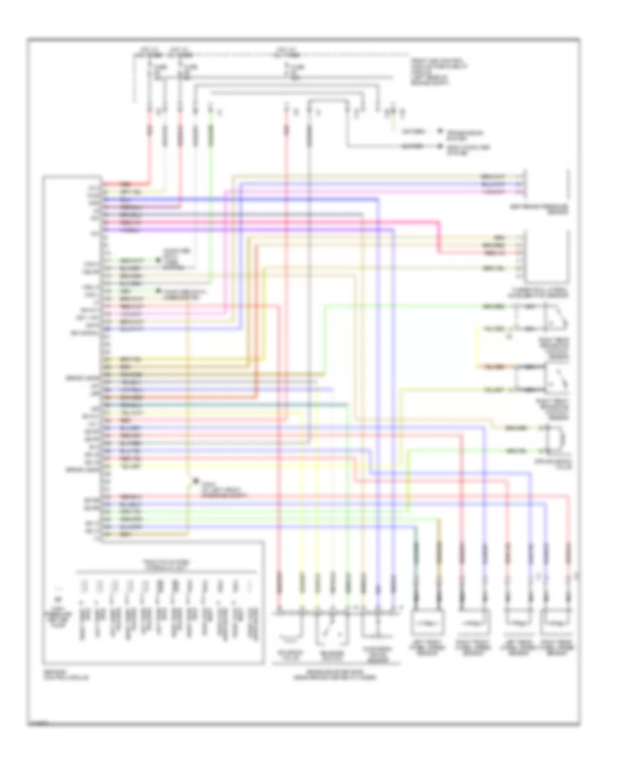
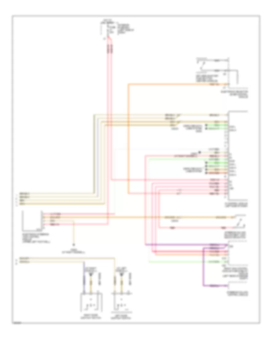
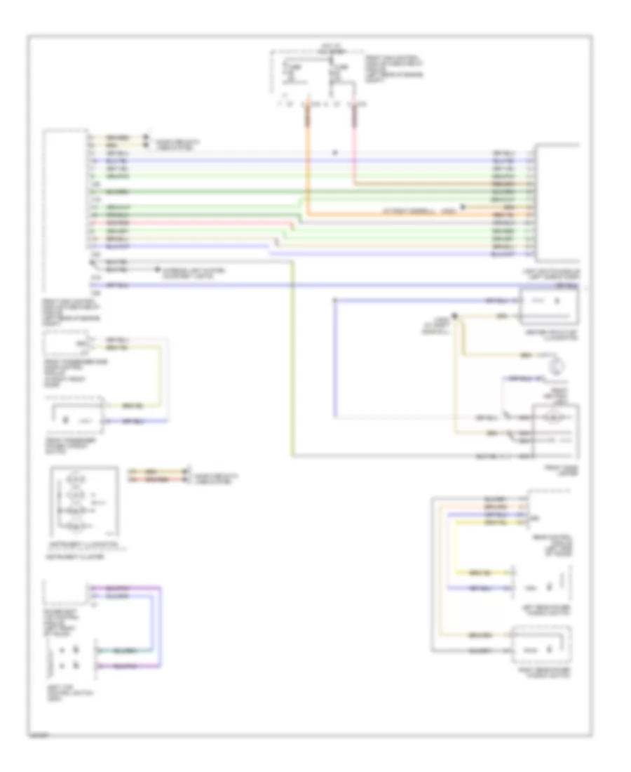
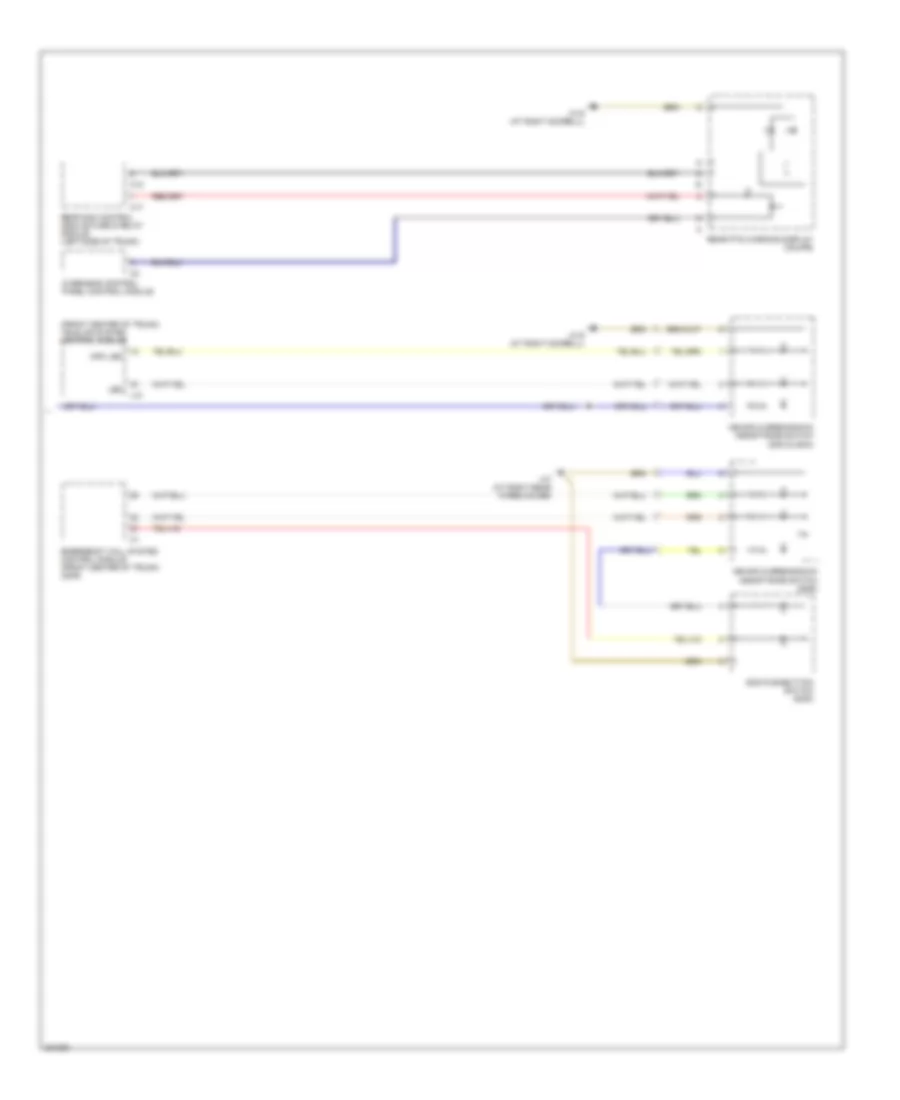
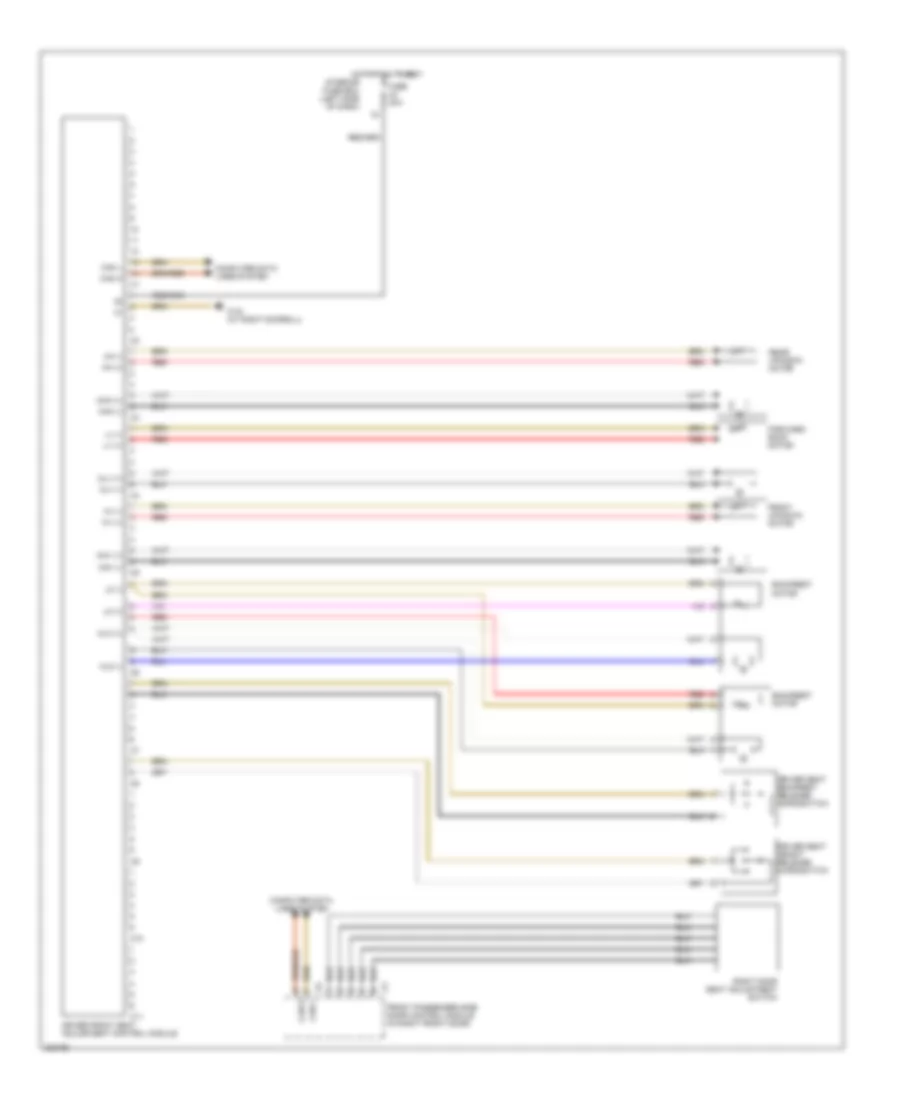
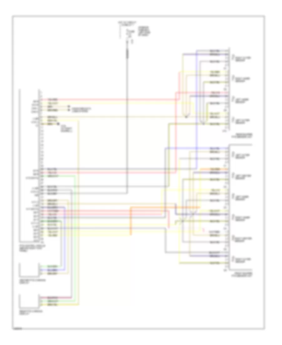
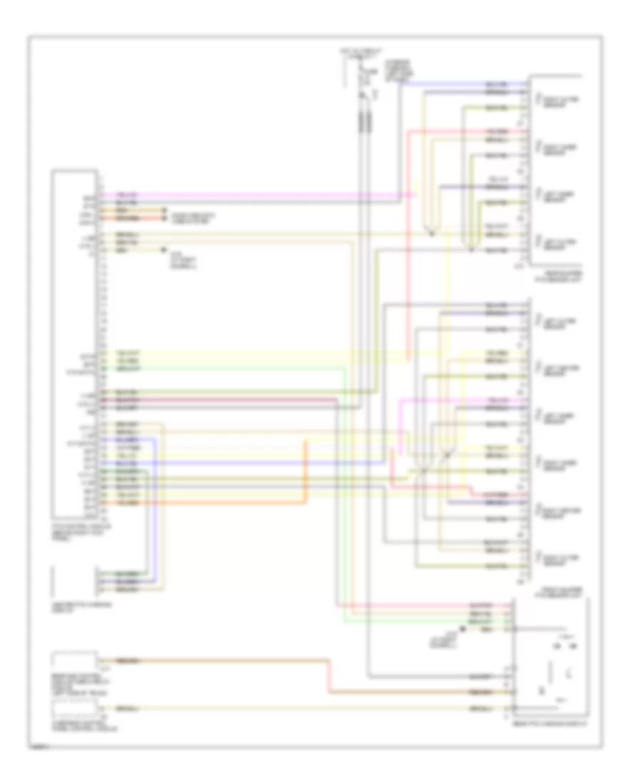
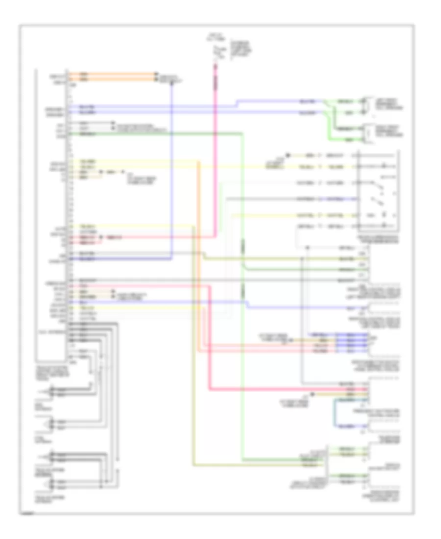
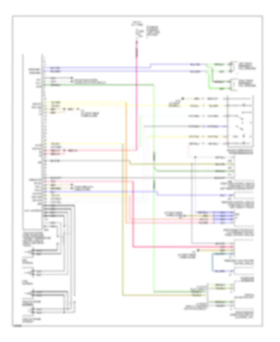
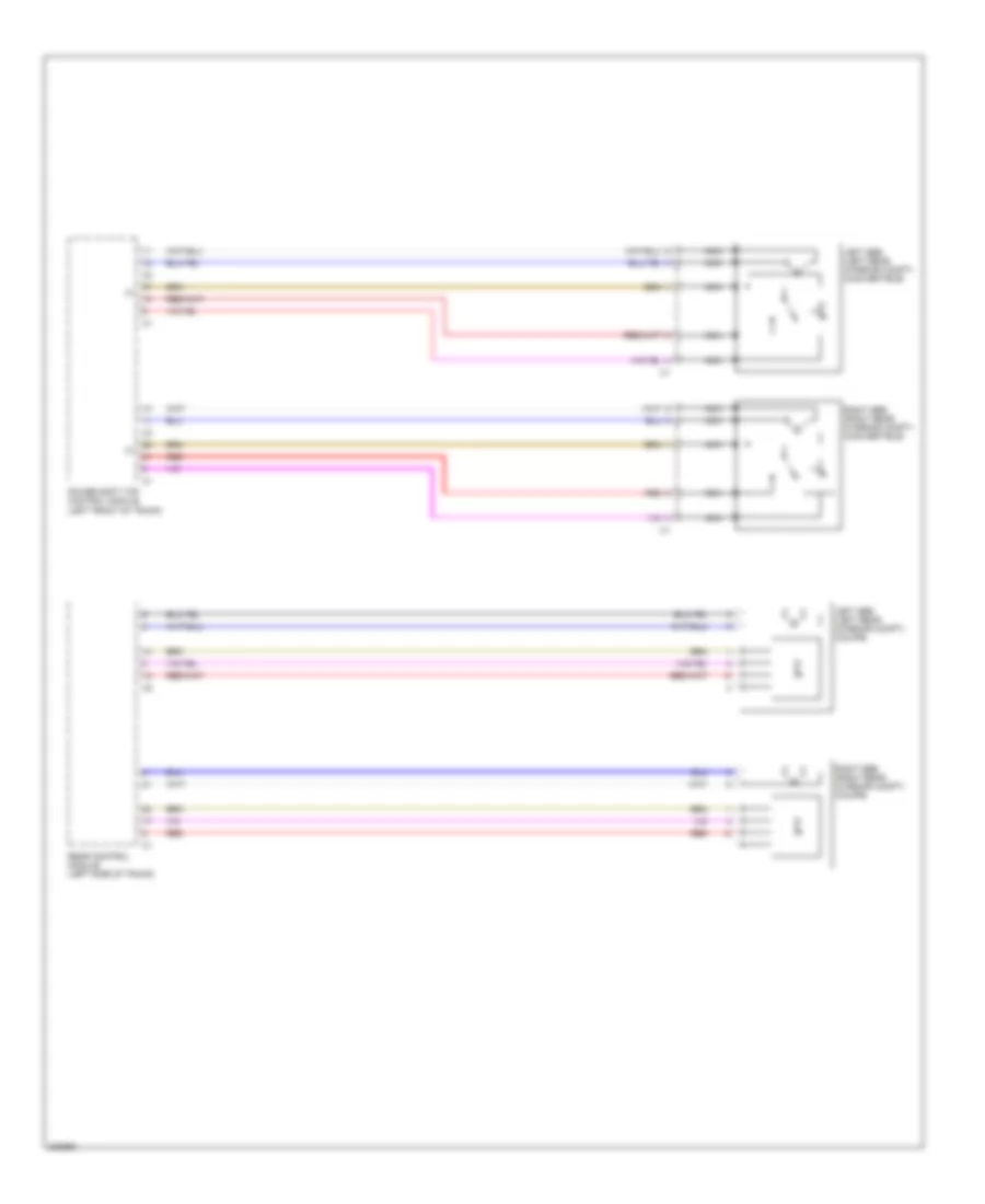
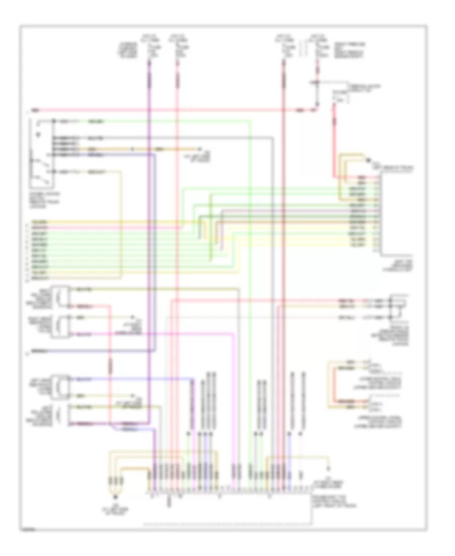
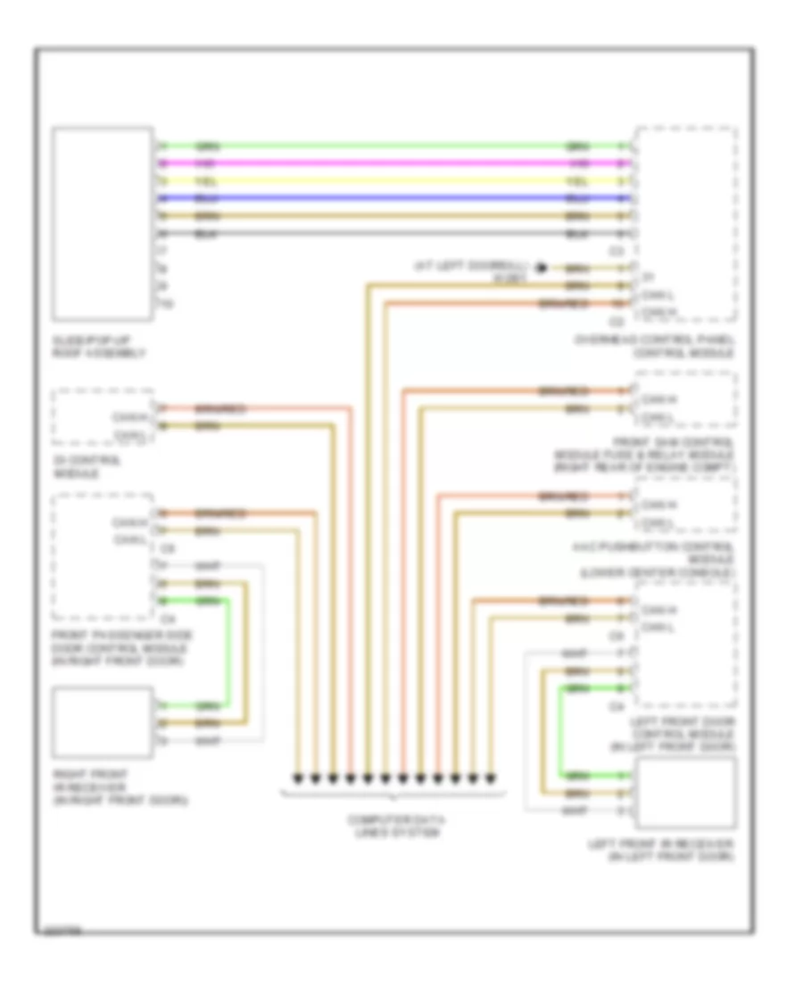
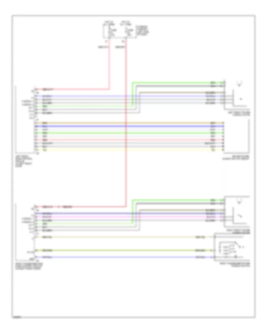
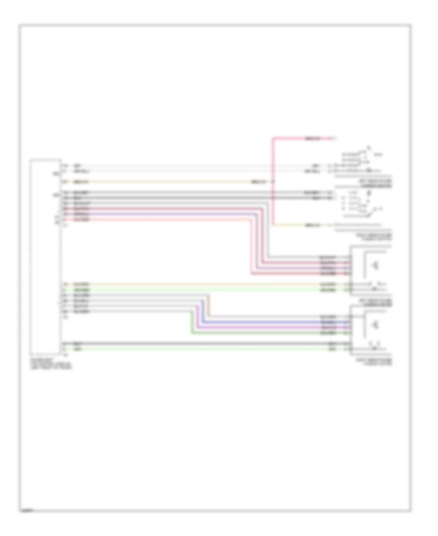
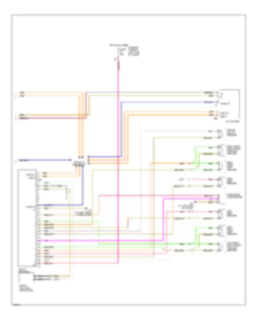
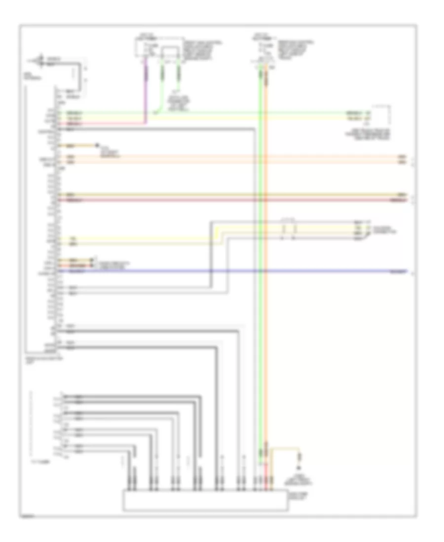
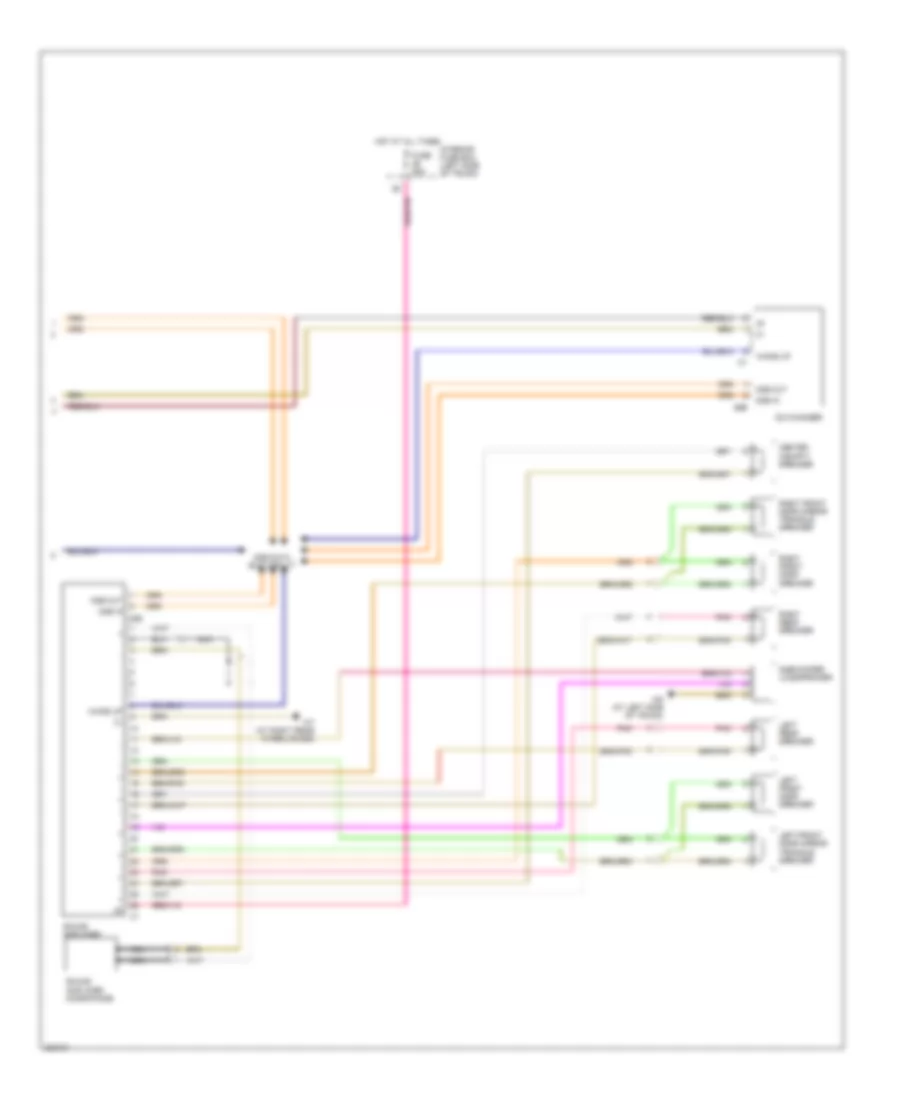
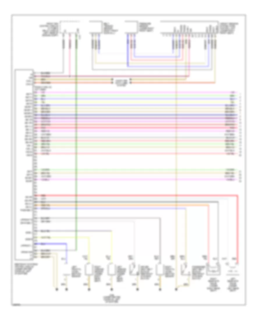
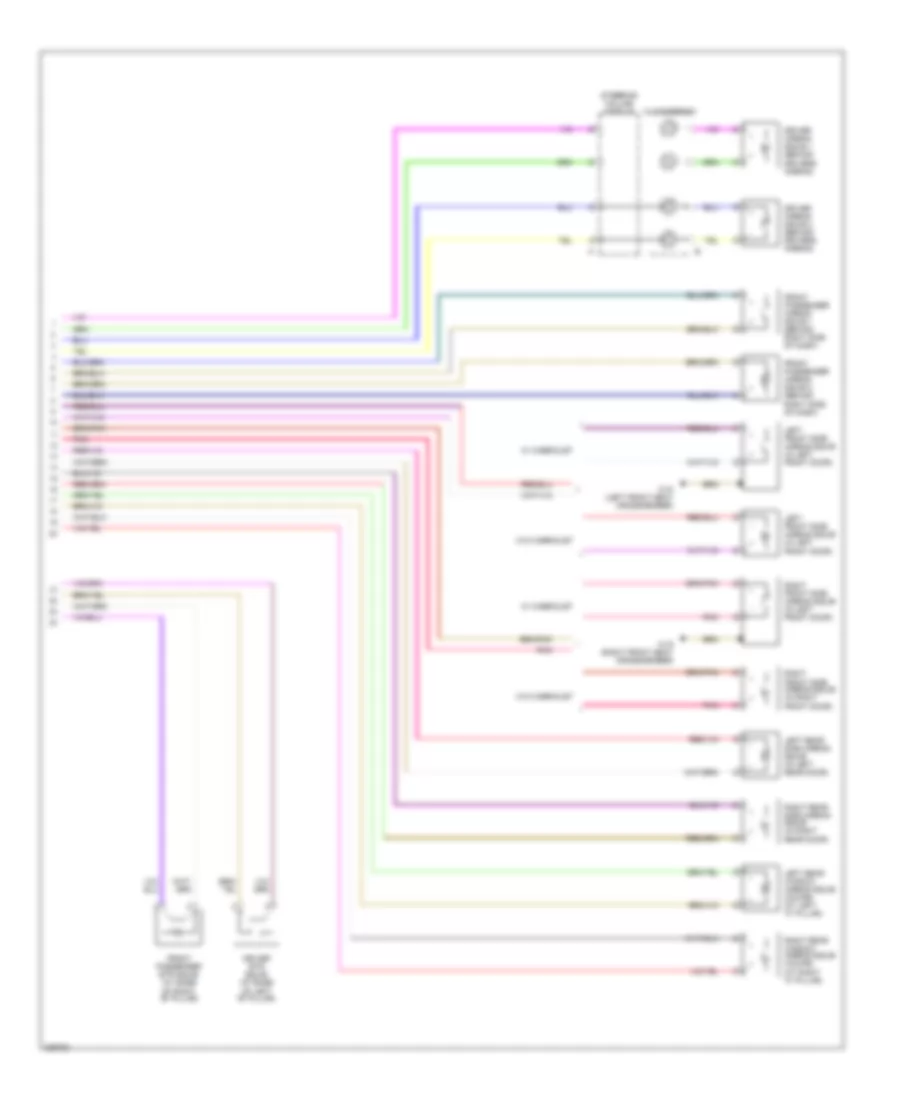
AIR CONDITIONING
Automatic A/C Wiring Diagram for Mercedes-Benz CLK320 2005
 https://portal-diagnostov.com/license.html
Automotive Electricians Portal FZCO
Automotive Electricians Portal FZCO
https://portal-diagnostov.com/license.html
https://portal-diagnostov.com/license.html
Automotive Electricians Portal FZCO
Automotive Electricians Portal FZCO
List of elements for Automatic A/C Wiring Diagram for Mercedes-Benz CLK320 2005:
- (in left front of engine compt) refrigerant pressure & temperature sensor
- 12v
- 15 ges.
- A/c recir- culation unit (right side of dash)
- A/c recirculation unit (right side of dash)
- Aac pushbutton control module (lower center console)
- Automatic climate control multifunction sensor (right rear of engine compt)
- Automatic climate control sun sensor (rear of engine hood)
- Blower motor
- Blower regulator
- C15
- C19
- C20
- Can h
- Can l
- Computer data lines system
- Data out
- Evaporator temperature sensor (left front footwell)
- Fresh air/recirculated air flaps actuator motor (under glove box)
- Front sam control module fuse & relay module (left rear of engine compt)
- Fuse 15a
- Fuse 40a
- Fuse 7.5a
- Hot at all times
- Instrument cluster
- Interior fuse box (left side of dash)
- Left footwell flap actuator motor (behind instru- ment panel)
- Left blending air flap actuator (left side of dash)
- Left defroster vent flap actuator motor (right side of instrument panel)
- Left fresh air flap actuator (front middle console)
- Nca
- Rear blower electronic selector wheel
- Rear blower motor (in middle console)
- Rear blower motor control module (lower center console)
- Red
- Right footwell flap actuator motor (right side of dash)
- Right blending air flap actuator (under glove box)
- Right defroster vent flap actuator motor (center of dash)
- Right fresh air flap actuator (front middle console)
- Signal
- Upper control panel control module (upper center cockpit)
- W16/4 (right front of engine compt)
- W28/1 (at left doorsill)
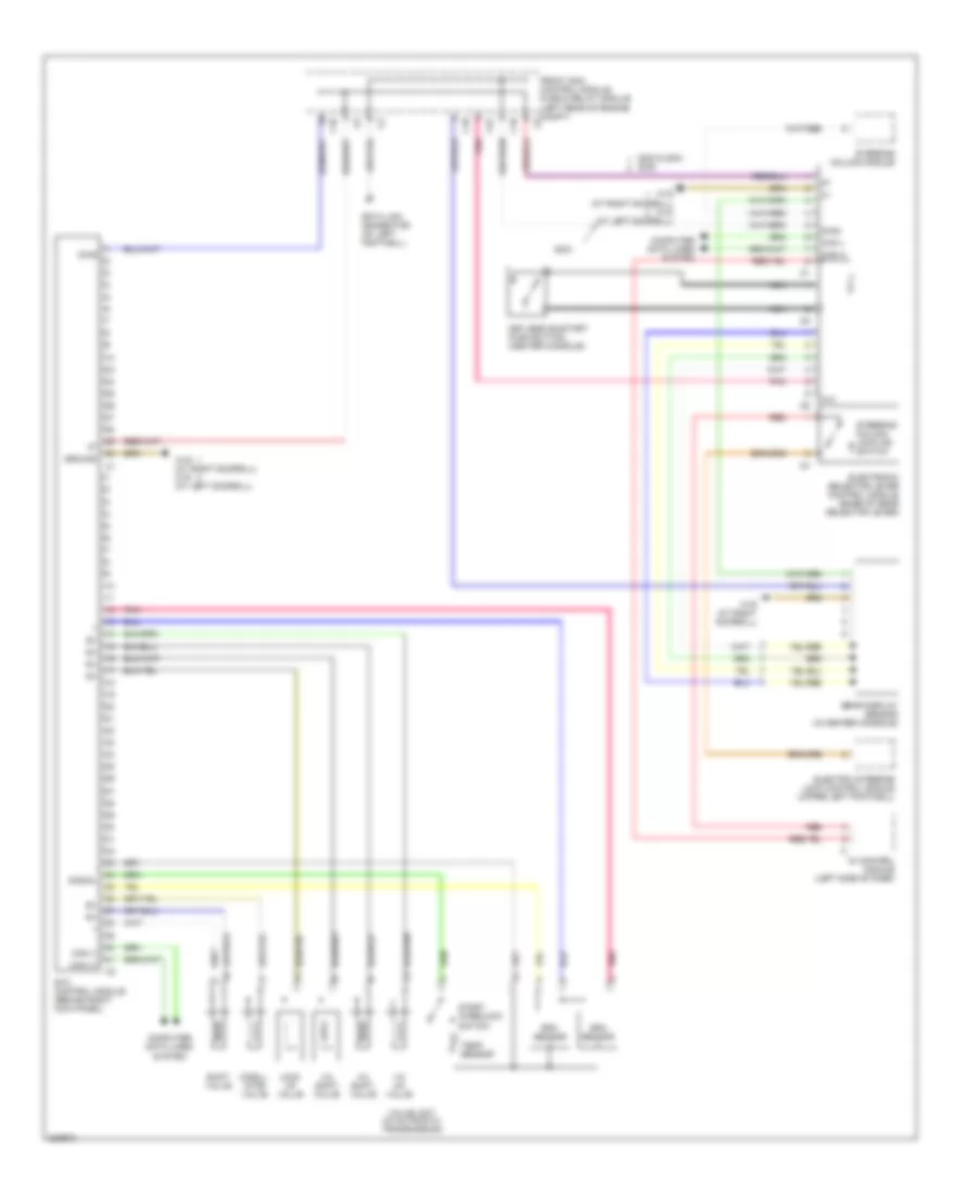
ANTI-LOCK BRAKES
Anti-lock Brakes Wiring Diagram for Mercedes-Benz CLK320 2005
List of elements for Anti-lock Brakes Wiring Diagram for Mercedes-Benz CLK320 2005:
- +5v
- Ba mv+
- Ba mv-
- Bla
- Body computer system
- Brake booster (bas) (near brake master cylinder)
- Brake wear
- C10
- C13
- C26
- Can h
- Can l
- Computer data lines system
- Dg1 +15v
- Dg1-signal
- Dg1m
- Diag
- Diaphragm travel sensor
- Esp brake pressure sensor
- Esp/bas control module
- Front axle inlet
- Front axle switchover
- Front sam control module fuse & relay module (left rear of engine compt)
- Fuse 40a
- Fuse 50a
- Fuse 5a
- High- pressure return pump
- Hold left front
- Hot at all times
- Inlet rear axle
- Left front release
- Left front wheel speed sensor
- Left rear hold
- Left rear wheel speed sensor
- Ls1
- Ls2
- Lsr
- Mp-
- Mps
- Nca
- Rear axle switchover
- Red
- Release left rear
- Release right rear
- Release switch
- Right front brake pad contact sensor
- Right front hold
- Right front release
- Right front wheel speed sensor
- Right rear brake pad contact sensor
- Right rear hold
- Right rear wheel speed sensor
- Solenoid valve
- Sps solenoid valve
- Ss lf
- Ss lr
- Ss rf
- Ss rr
- Traction system hydraulic unit
- Transmission system
- Turnrate & lateral acceleration sensor
- Um 1
- Um 2
- Vss lf
- Vss rf
- W16/3 (at left front of engine compt)
ANTI-THEFT
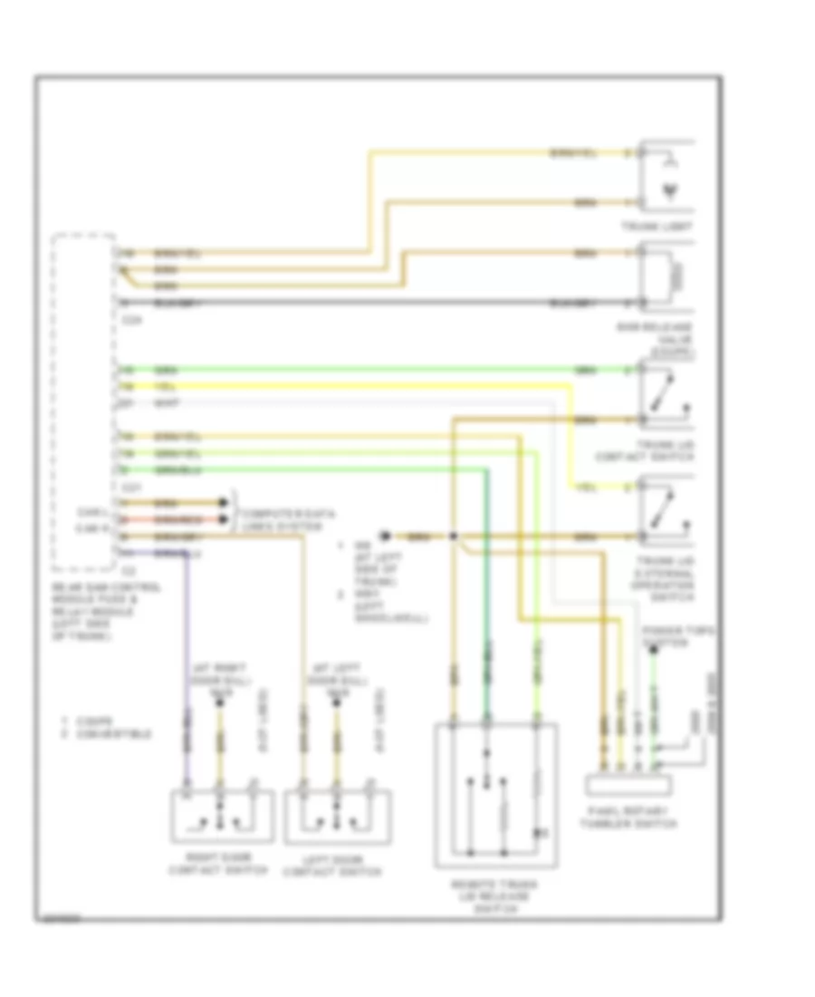
Remote Keyless Entry/Anti-theft Alarm Wiring Diagram, Convertible (1 of 2) for Mercedes-Benz CLK320 2005
List of elements for Remote Keyless Entry/Anti-theft Alarm Wiring Diagram, Convertible (1 of 2) for Mercedes-Benz CLK320 2005:
- (at left door sill) w18
- (at right door sill) w19
- (at right rear wheelhouse) w7
- (left side of trunk) rear sam control module fuse & relay module
- Alarm signal horn (in right front wheelhouse)
- Ata inclination sensor (left side of trunk)
- C28
- D in
- Enable
- Interior module keyless go control module (middle console between front seats)
- Keylees go rear bumper antenna
- Keyless go interior antenna (2005)
- Keyless go rf antenna cable end
- Keyless go trunk antenna
- Keyless go trunk lid pushbutton
- Left door handle switch
- Left door keyless go antenna
- Left door keyless go control module (in left door)
- Left front opening assist motor
- Lf1
- Lf2
- N.c.
- Nca
- Rear module keyless go control module (left side of trunk)
- Right door handle switch
- Right door keyless go antenna
- Right door keyless go control module (in right door)
- Right front opening assist motor
- Shield
- Signal
- Vcc
- W16/4 (right front of engine compt)
- W6 (at left side of trunk)
- X35/1
- X35/2
Remote Keyless Entry/Anti-theft Alarm Wiring Diagram, Convertible (2 of 2) for Mercedes-Benz CLK320 2005
List of elements for Remote Keyless Entry/Anti-theft Alarm Wiring Diagram, Convertible (2 of 2) for Mercedes-Benz CLK320 2005:
- (at left door sill) w18
- (at right door sill) w19
- (not used)
- 15r
- 30z
- C19
- C20
- Can h
- Can l
- Computer data lines system
- Computer data lines system (2005)
- Di control module (left side of dash)
- Diag
- Electronic selector lever control module
- Electronic steering lock control module (upper left footwell)
- Front sam control module fuse & relay module (left rear of engine compt)
- Fuse 20a
- Hot at all times
- Interior fuse box (left side of dash)
- Keyless go/start push buttom (center console)
- Left door contact switch
- N.c.
- Nca
- Pnk/red
- Red
- Right door contact switch
- Steering column adjustment lock indicator switch
- Steering column control module
- W28/2 (at right doorsill)
- X35/33
Remote Keyless Entry/Anti-theft Alarm Wiring Diagram, Except Convertible (1 of 2) for Mercedes-Benz CLK320 2005
List of elements for Remote Keyless Entry/Anti-theft Alarm Wiring Diagram, Except Convertible (1 of 2) for Mercedes-Benz CLK320 2005:
- (at left door sill) w18
- (at left side of trunk) w6
- (at right door sill) w19
- (left side of trunk) rear sam control module fuse & relay module
- Alarm signal horn (in right front wheelhouse)
- Ata inclination sensor (left side of trunk)
- C28
- D in
- Enable
- Interior module keyless go control module (middle console between front seats)
- Keylees go rear bumper antenna
- Keyless go interior antenna (2005)
- Keyless go rf antenna cable end
- Keyless go trunk antenna
- Keyless go trunk lid pushbutton
- Left door handle switch
- Left door keyless go antenna
- Left door keyless go control module (in left door)
- Left front opening assist motor
- Lf1
- Lf2
- N.c.
- Nca
- Rear module keyless go control module (left side of trunk)
- Right door handle switch
- Right door keyless go antenna
- Right door keyless go control module (in right door)
- Right front opening assist motor
- Shield
- Signal
- Vcc
- W16/4 (right front of engine compt)
- W6 (at left side of trunk)
- X35/1
- X35/2
Remote Keyless Entry/Anti-theft Alarm Wiring Diagram, Except Convertible (2 of 2) for Mercedes-Benz CLK320 2005
List of elements for Remote Keyless Entry/Anti-theft Alarm Wiring Diagram, Except Convertible (2 of 2) for Mercedes-Benz CLK320 2005:
- (at left door sill) w18
- (at right door sill) w19
- (not used)
- 15r
- 30z
- C19
- C20
- Can h
- Can l
- Computer data lines system
- Computer data lines system (2005)
- Di control module (left side of dash)
- Diag
- Electronic selector lever control module
- Electronic steering lock control module (upper left footwell)
- Front sam control module fuse & relay module (left rear of engine compt)
- Fuse 20a
- Hot at all times
- Interior fuse box (left side of dash)
- Keyless go/start push buttom (center console)
- Left door contact switch
- N.c.
- Nca
- Pnk/red
- Red
- Right door contact switch
- Steering column adjustment lock indicator switch
- Steering column control module
- W28/2 (at right doorsill)
- X35/33
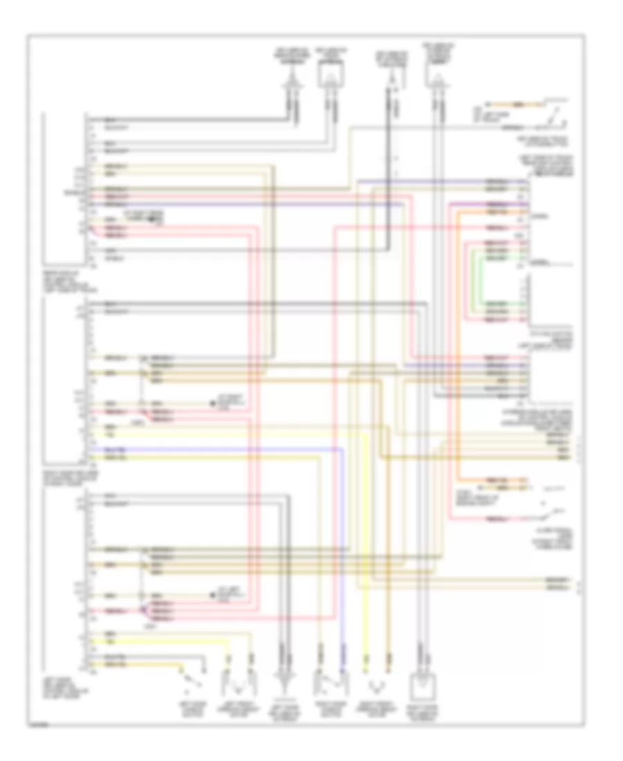
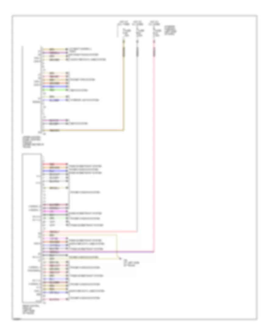
BODY CONTROL MODULES
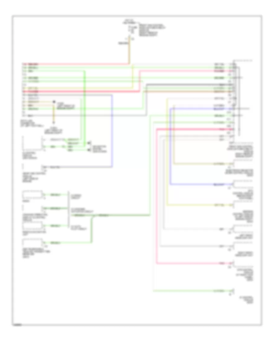
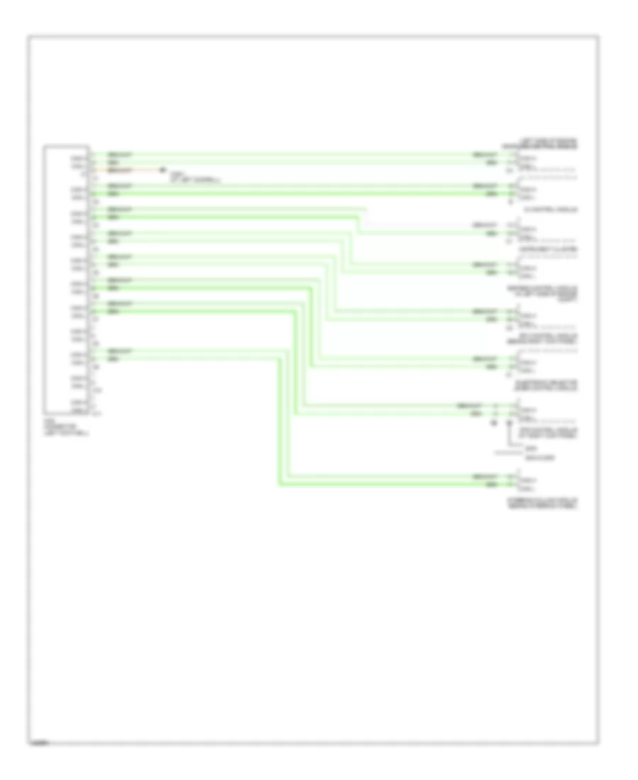
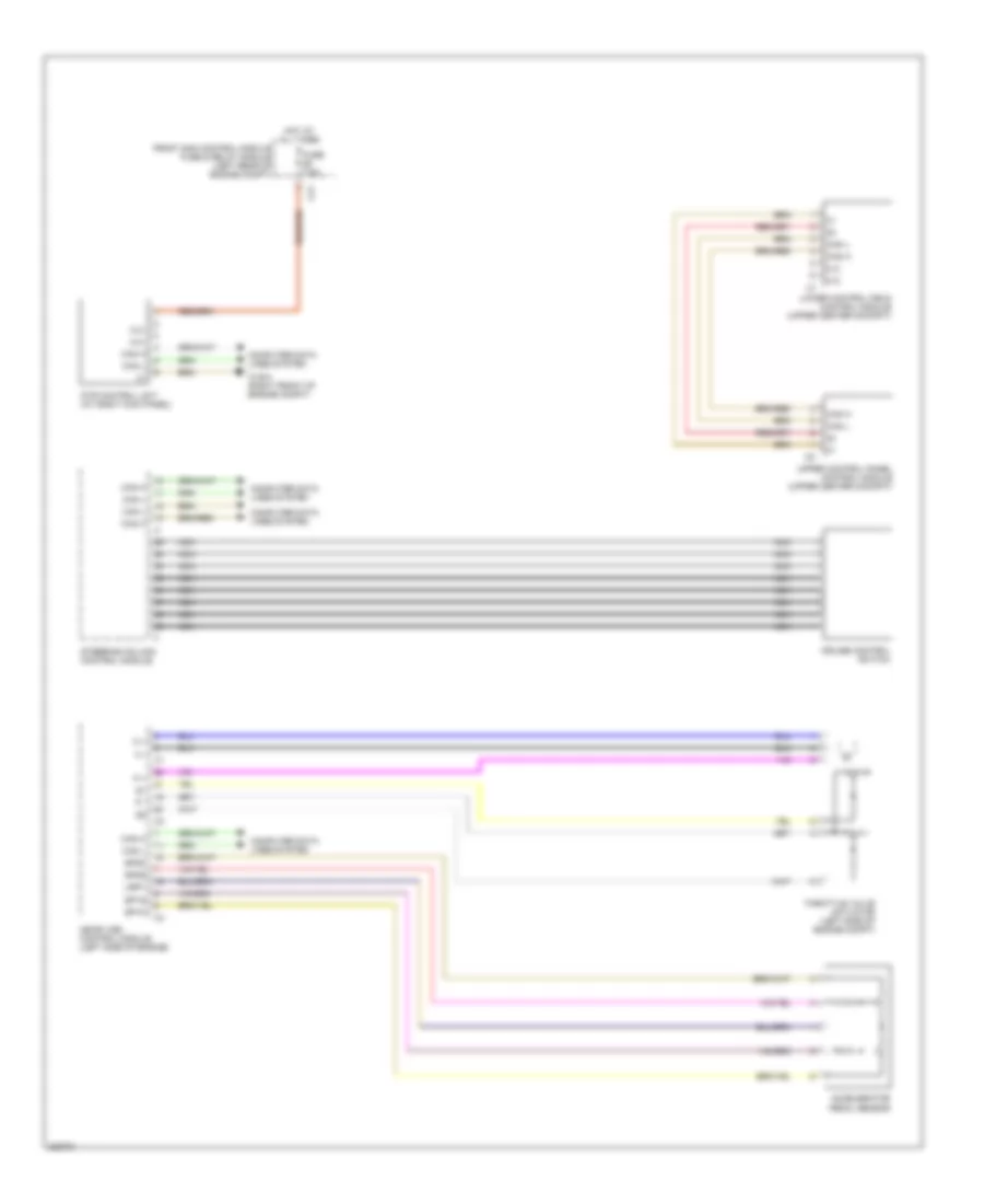
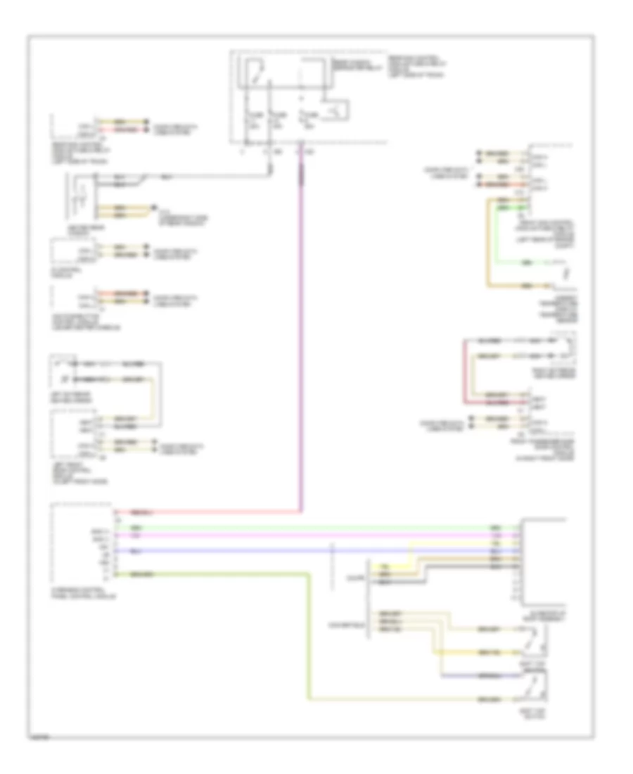
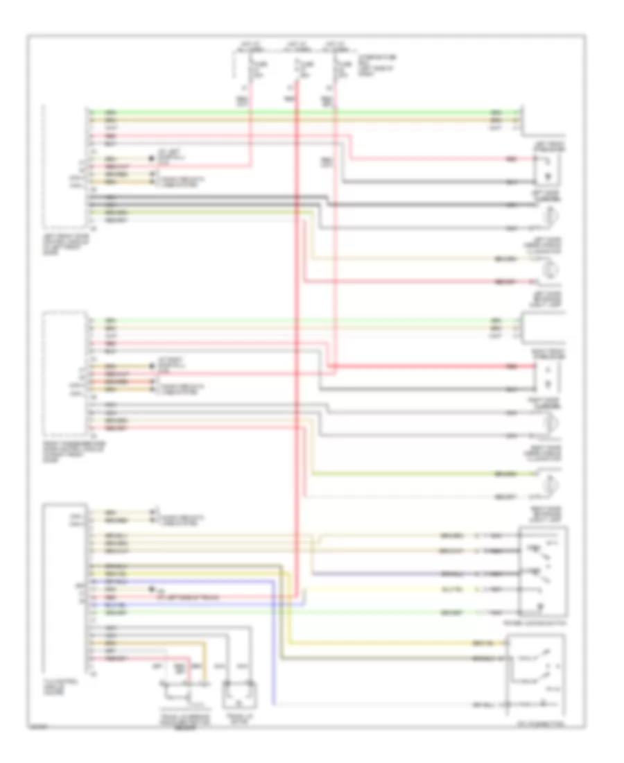
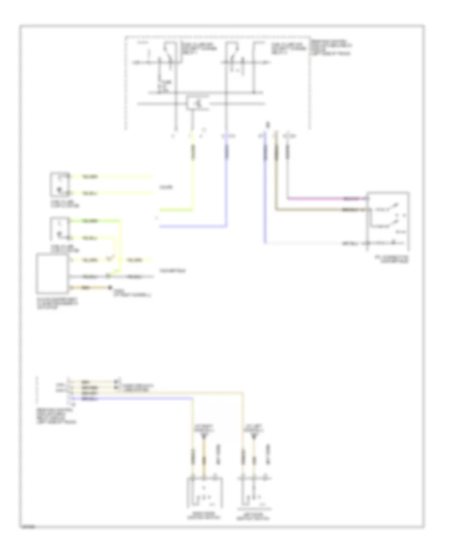
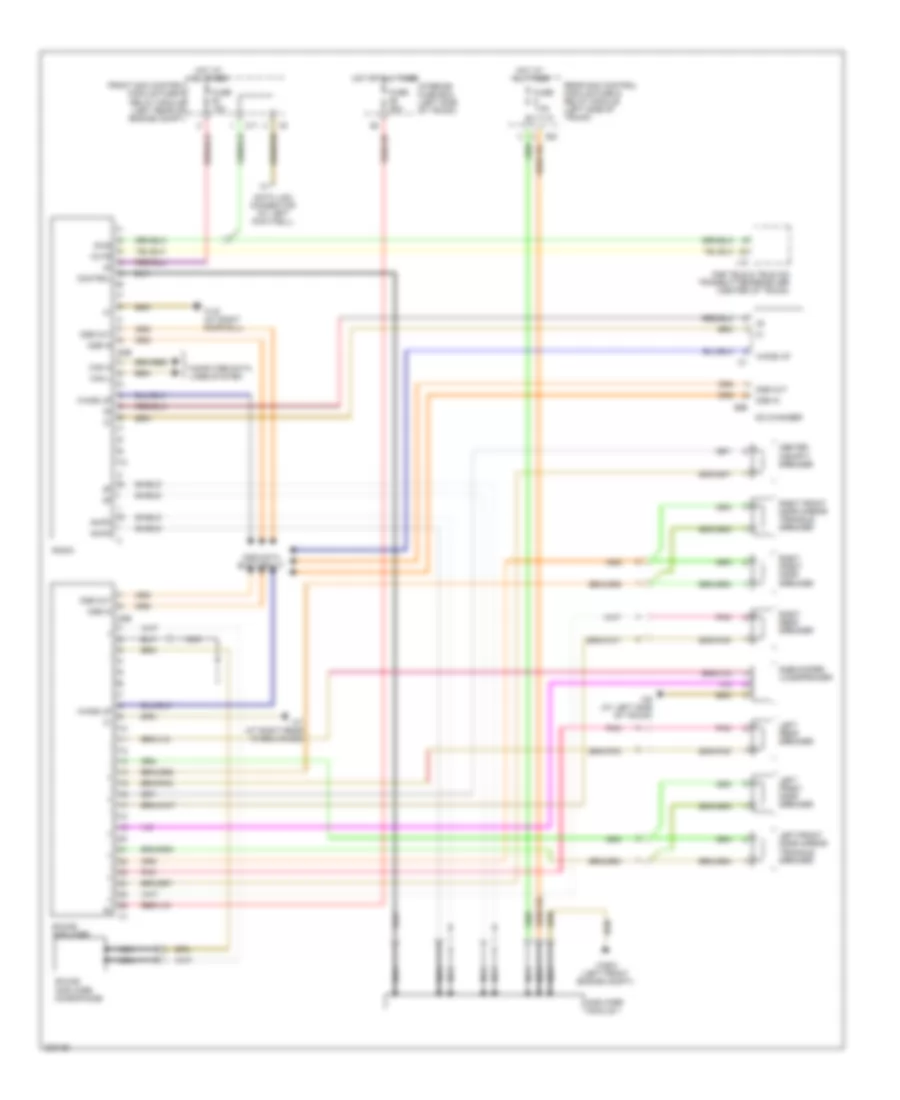
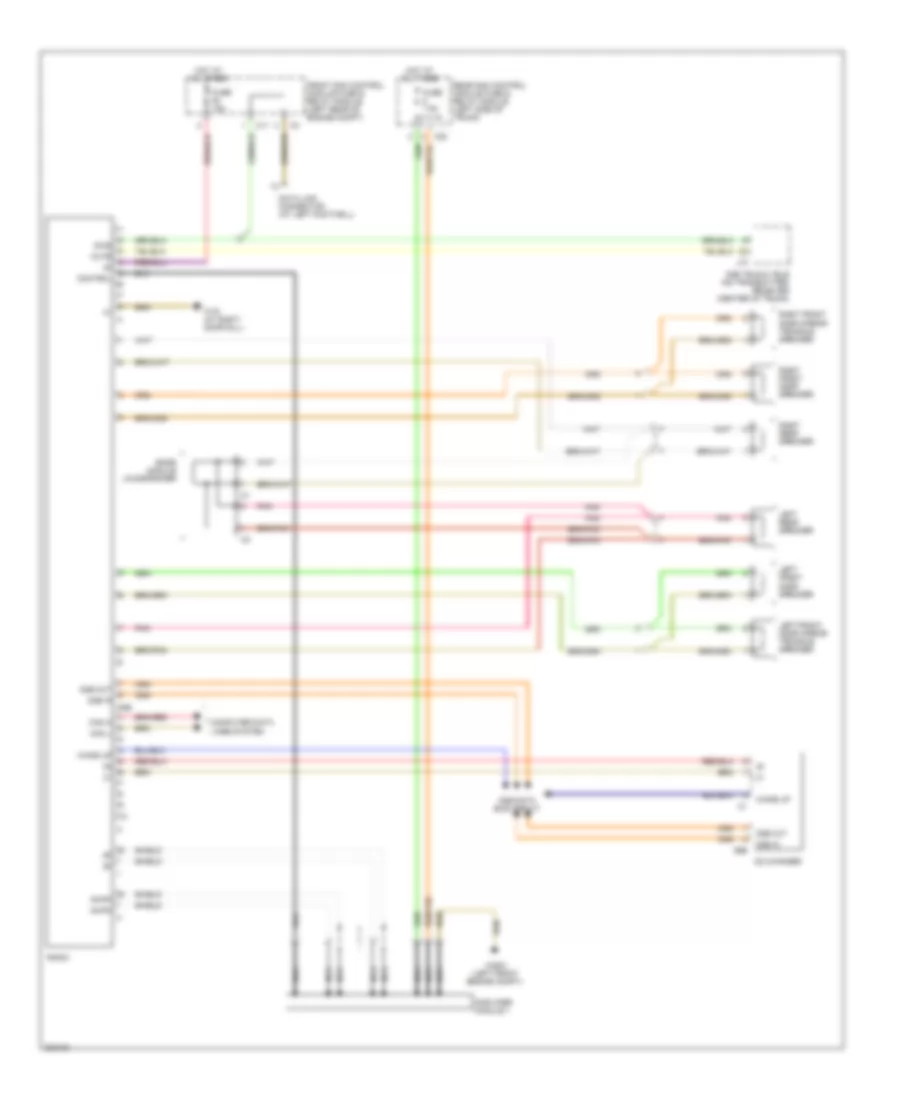
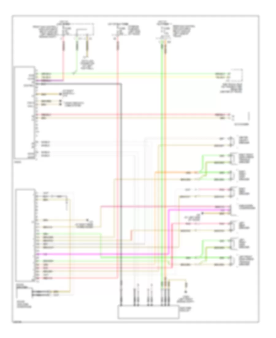
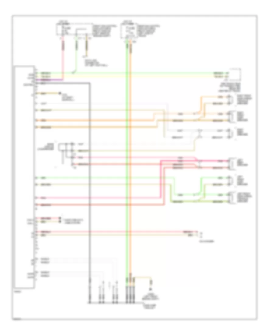
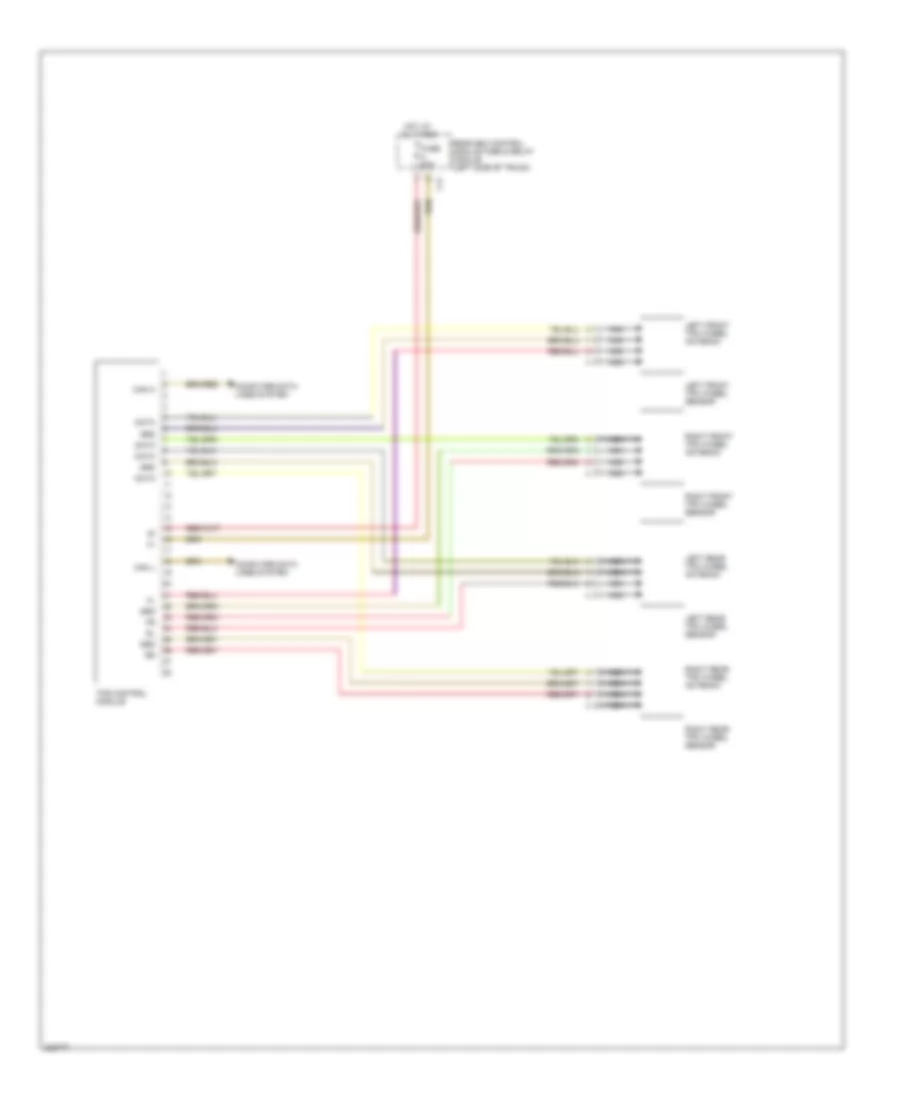
Front & Rear Controller Wiring Diagram for Mercedes-Benz CLK320 2005
List of elements for Front & Rear Controller Wiring Diagram for Mercedes-Benz CLK320 2005:
- (at right doorsill) w28/2
- 58d
- Air conditioning system
- Can h
- Can l
- Computer data lines system
- Fh h (+)
- Fh t (+)
- Fhs signal
- Fuse 30a
- H (+)
- H (-)
- H signal 1
- H signal 2
- Hot at all times
- Interior fuse box (left side of dash)
- Interior lights system
- Passive restraint system
- Power tops system
- Power windows system
- Rear control module (left side of trunk)
- Red
- Seats system
- Signal
- Upper control panel control module (upper center of trunk)
- W6 (at left side of trunk)
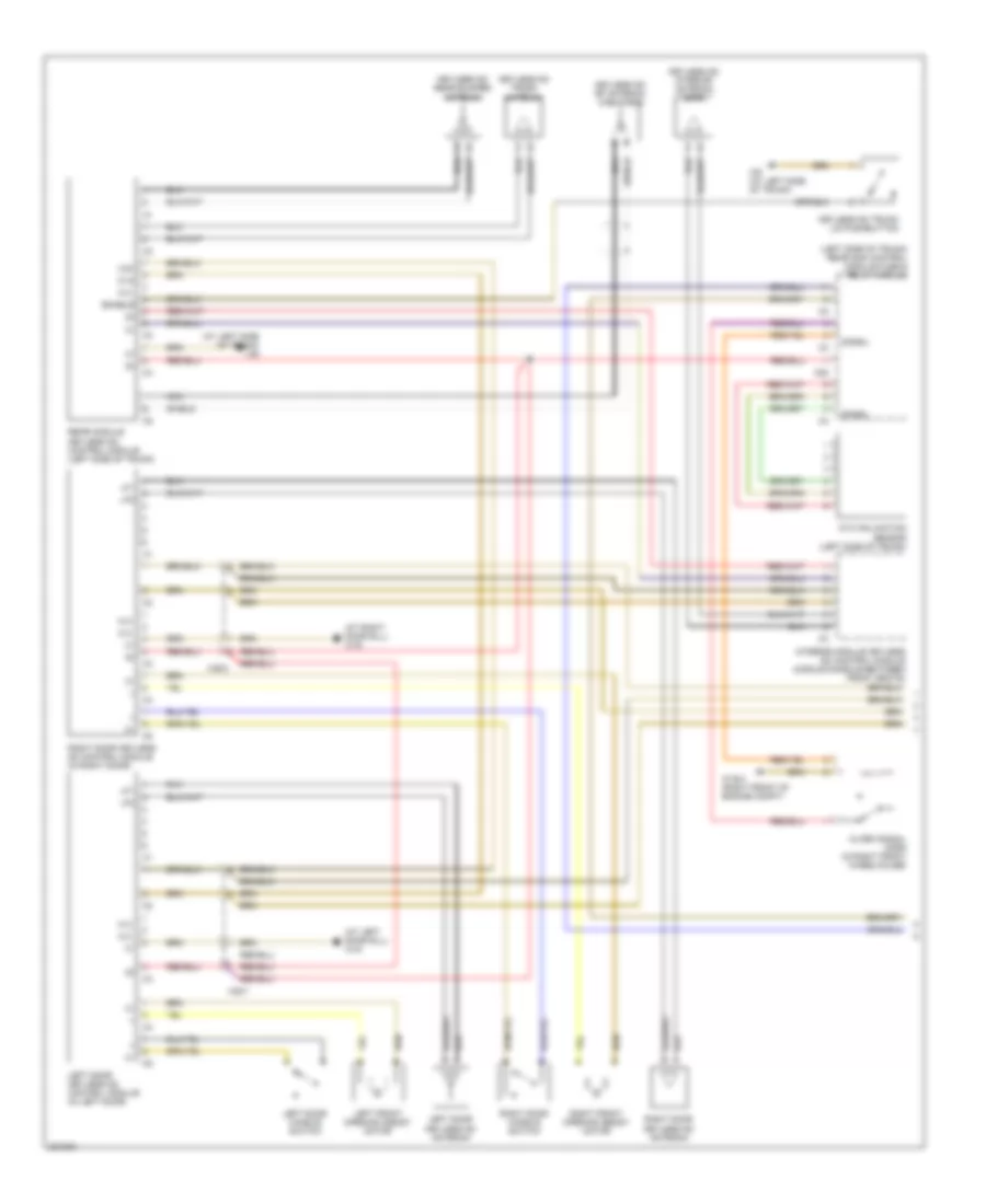
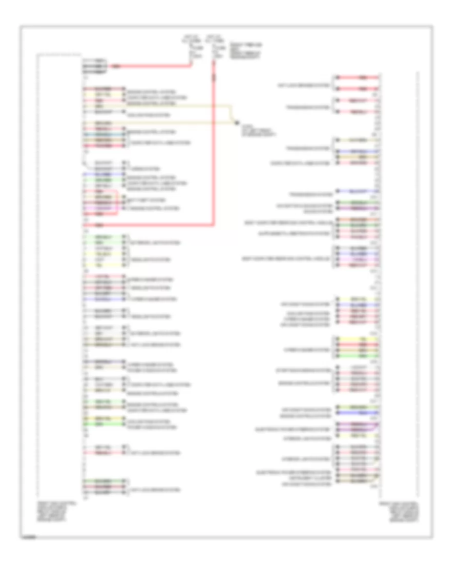
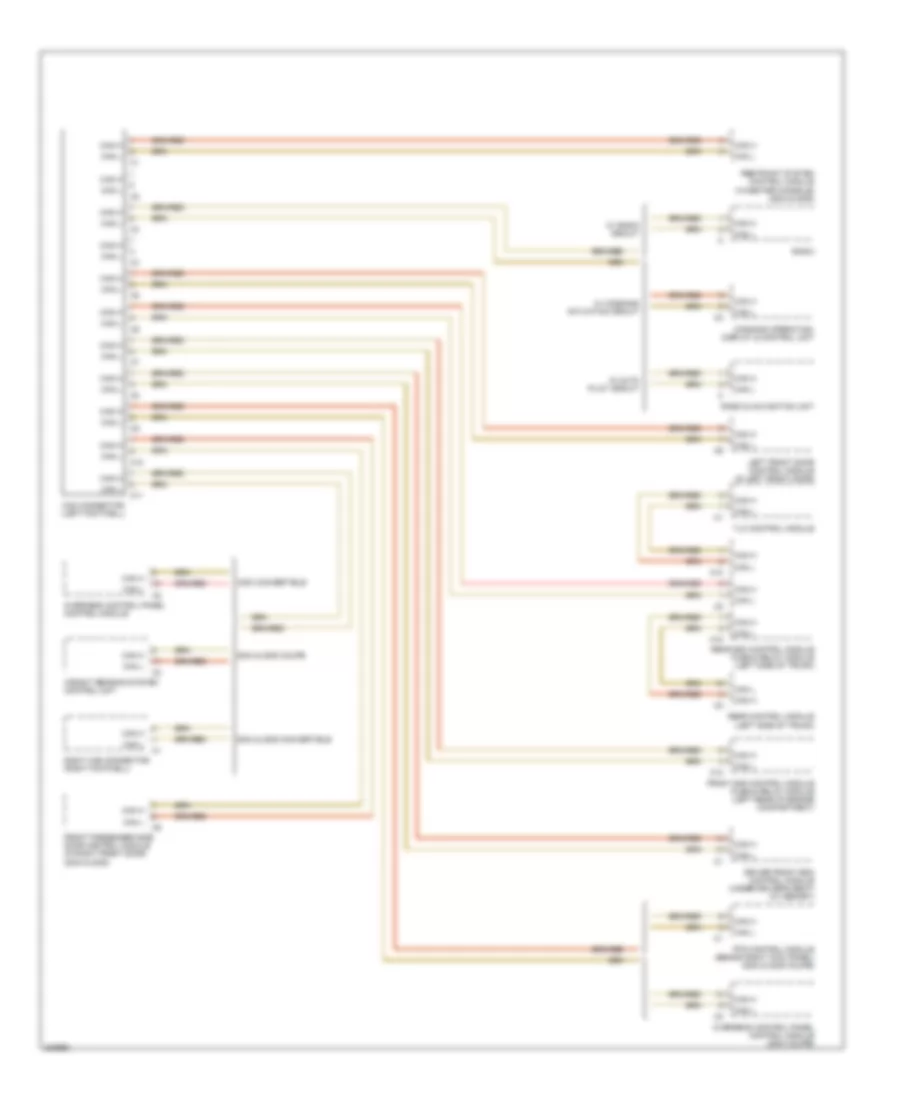
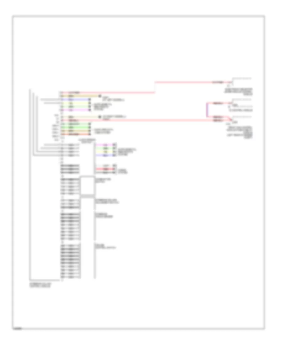
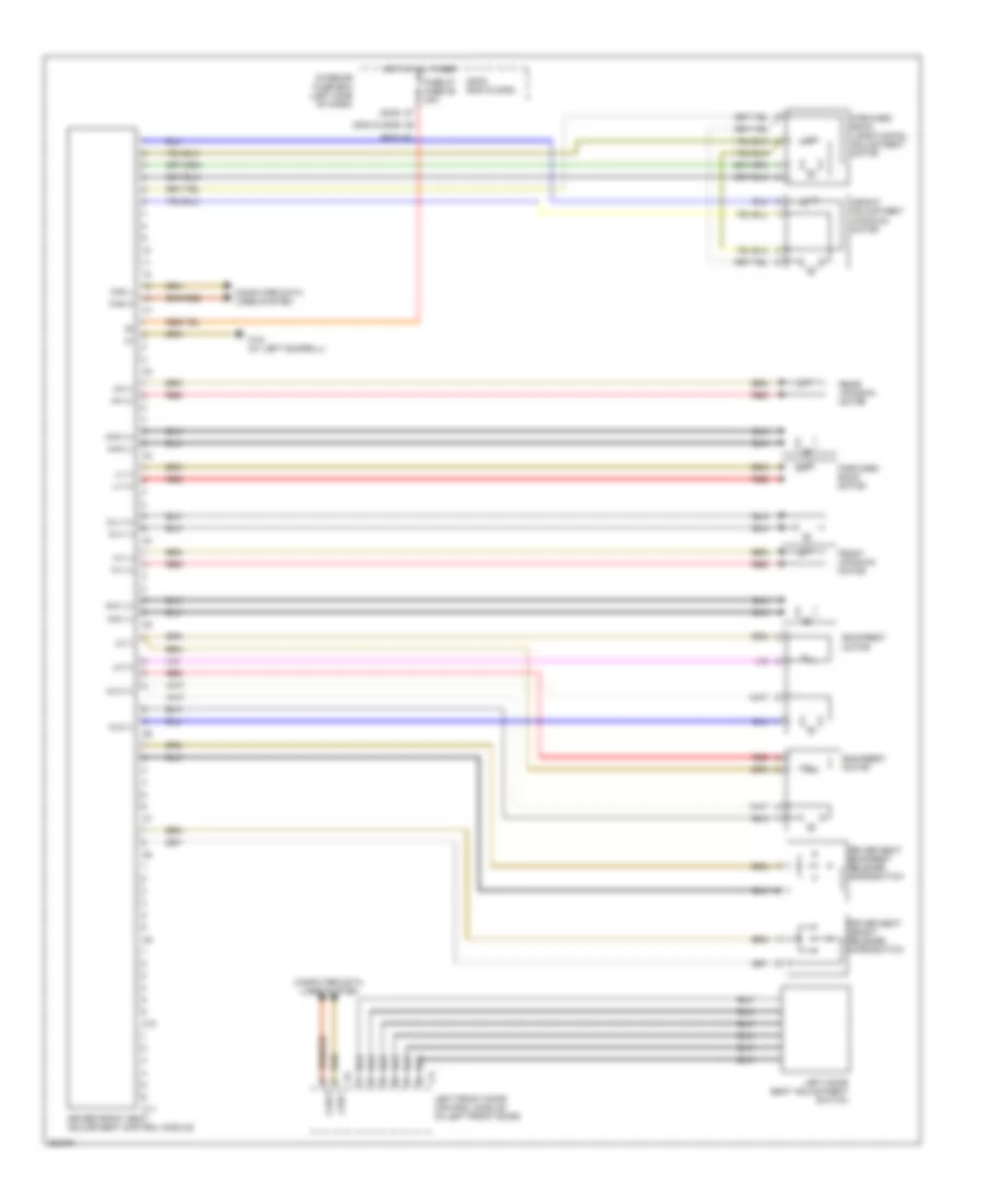
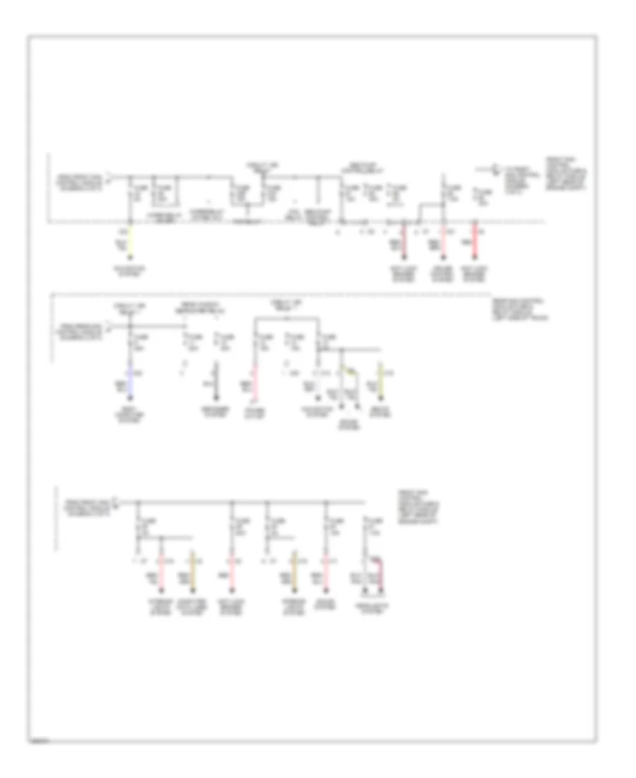
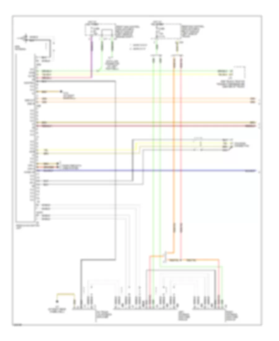
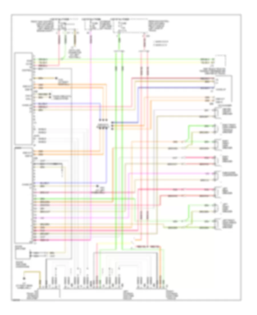
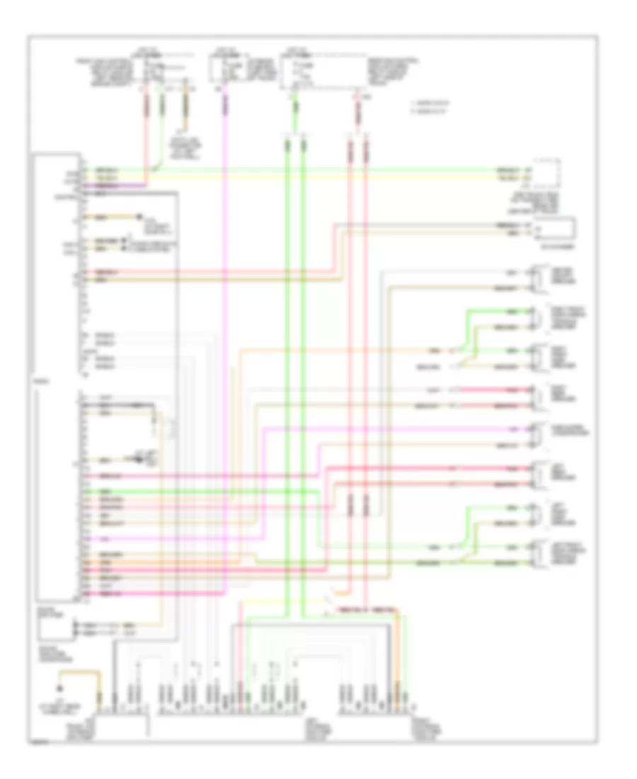
Front SAM Control Module Wiring Diagram (1 of 2) for Mercedes-Benz CLK320 2005
List of elements for Front SAM Control Module Wiring Diagram (1 of 2) for Mercedes-Benz CLK320 2005:
- Air conditioning system
- Anti-lock brake system
- Anti-lock brakes system
- Anti-theft system
- Body computer (rear sam control module)
- C10
- C11
- C12
- C13
- C14
- C15
- C16
- C17
- C18
- C19
- Computer data lines system
- Cooling fans system
- Electronic power steering system
- Engine control system
- Engine controls system
- Exterior lights system
- Front prefuse box (right rear of engine compt)
- Front sam control module fuse & relay module (left rear of engine compt)
- Fuse 200a
- Fuse 60a
- Headlights system
- Horns system
- Hot at all times
- Instrument cluster
- Interior lights system
- Navigation & sound system
- Nca
- Pnk/red
- Power windows system
- Red
- Sound system
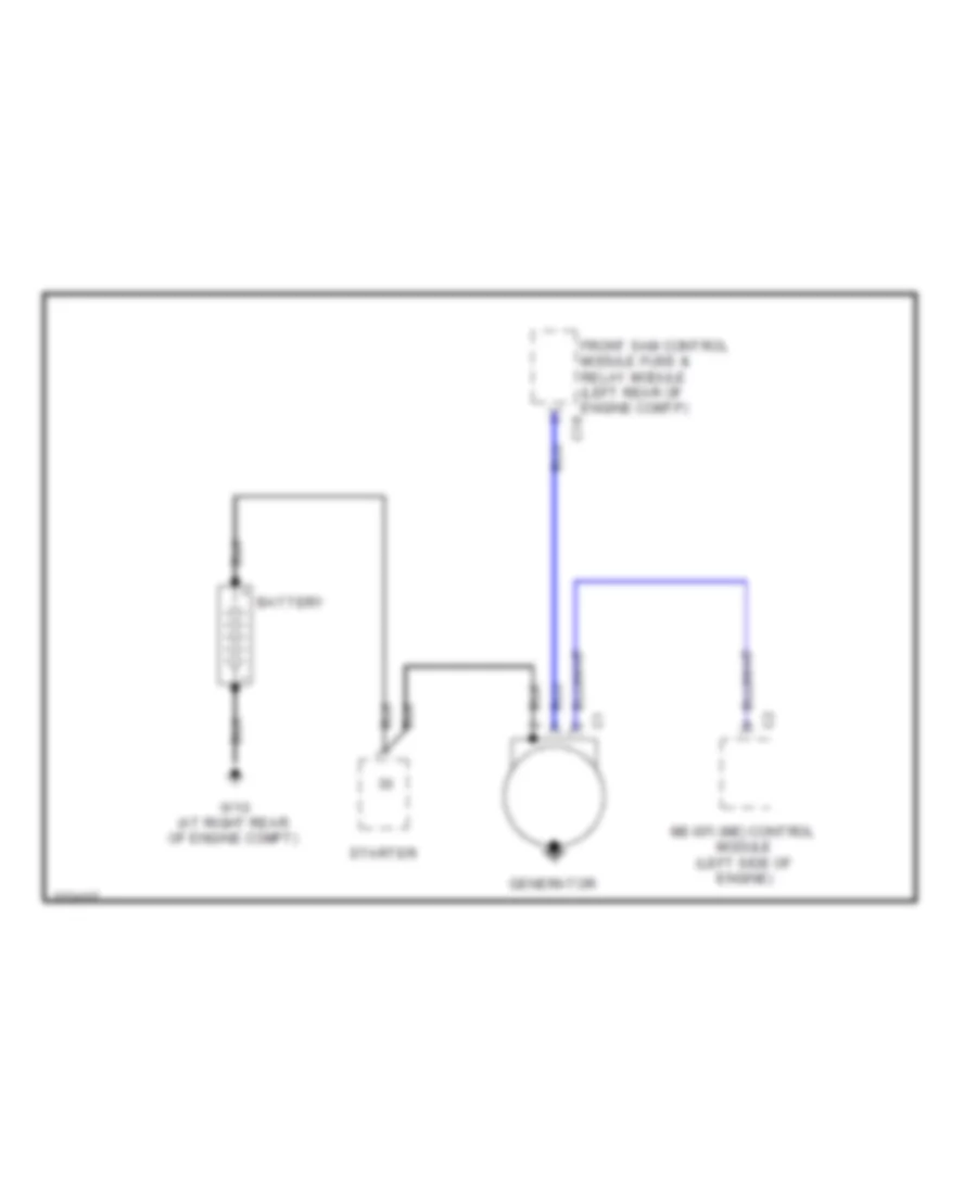
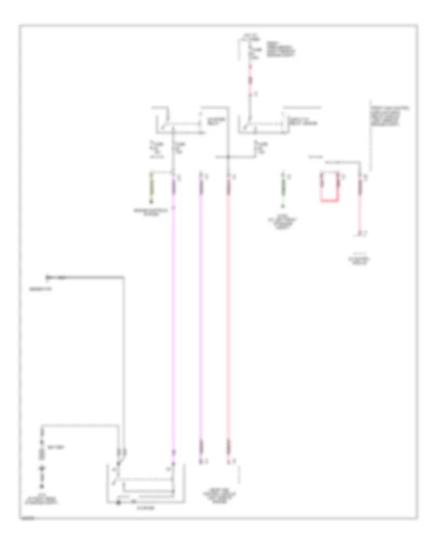
- Starting/charging system
- Transmission system
- W16/3 (at left front of engine compt)
- Wiper/washer system
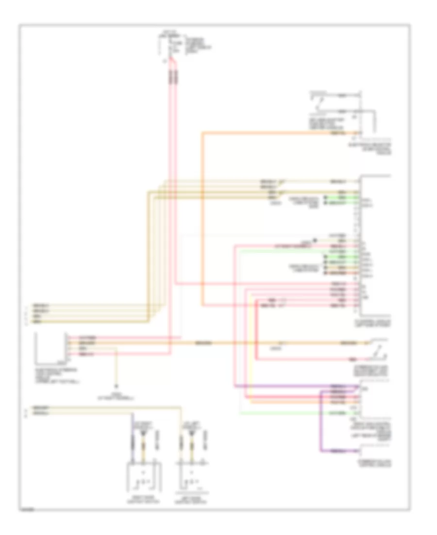
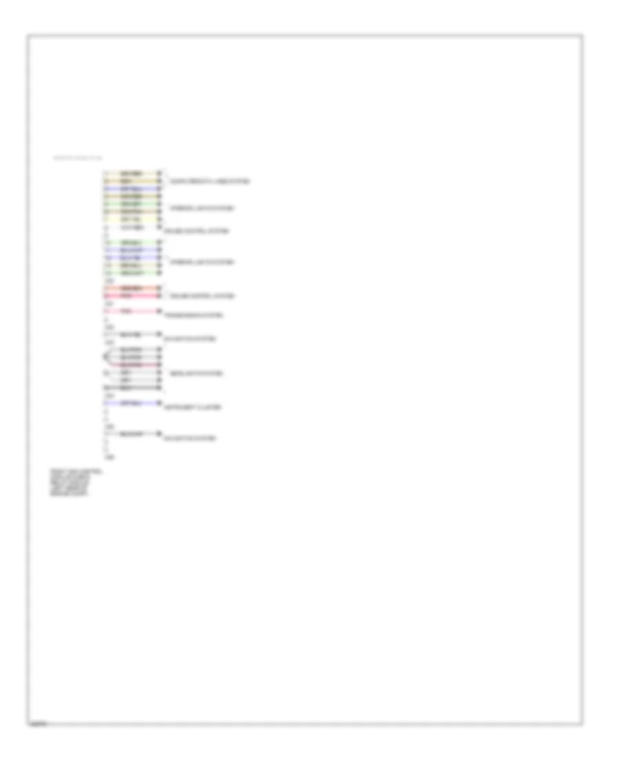
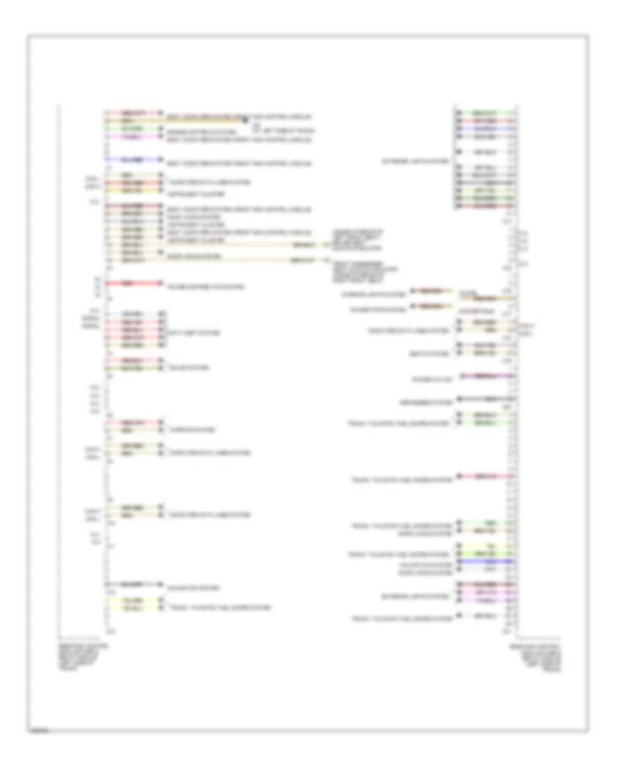
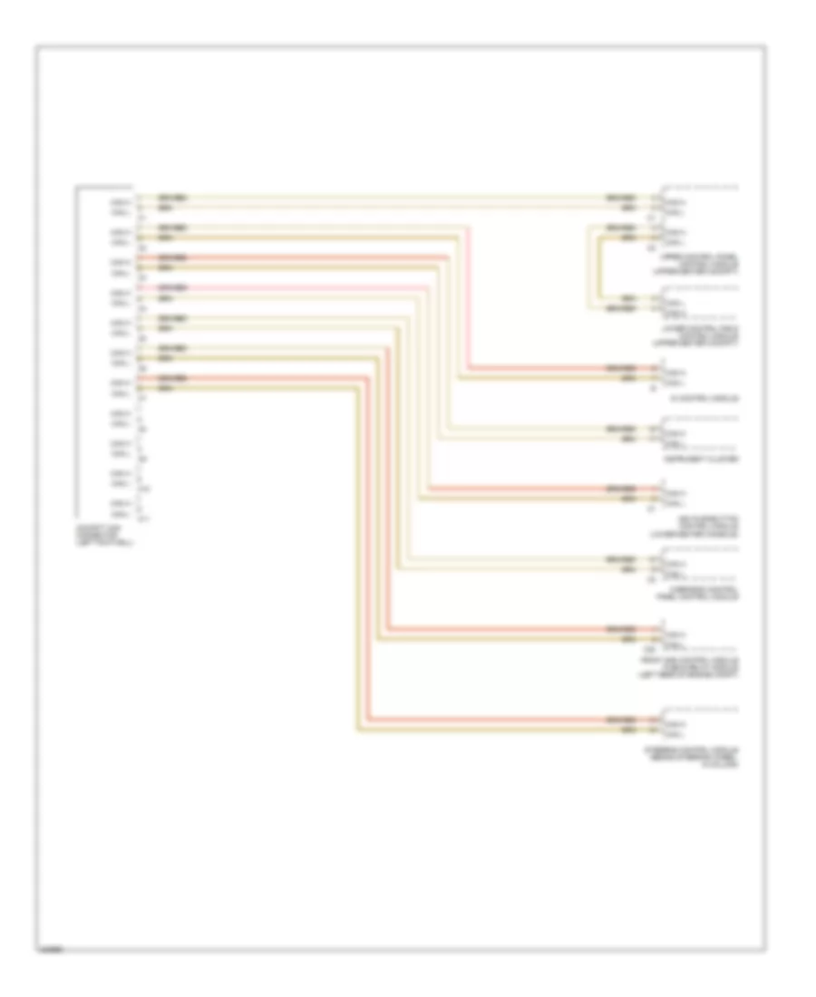
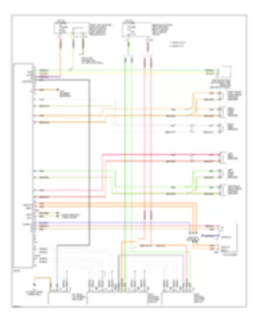
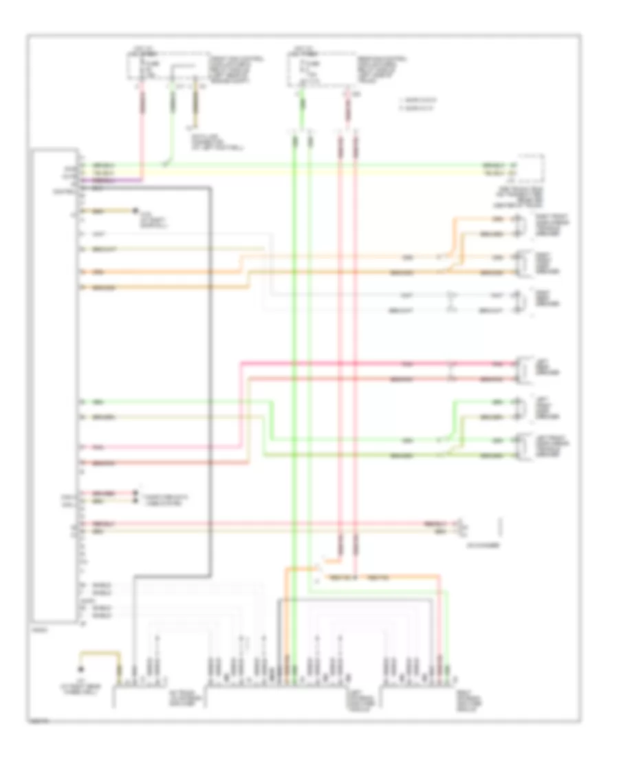
Front SAM Control Module Wiring Diagram (2 of 2) for Mercedes-Benz CLK320 2005
List of elements for Front SAM Control Module Wiring Diagram (2 of 2) for Mercedes-Benz CLK320 2005:
- C20
- C21
- C22
- C23
- C24
- C25
- C26
- Computer data lines system
- Cruise control system
- Front sam control module fuse & relay module (left rear of engine compt)
- Headlights system
- Instrument cluster
- Interior lights system
- Navigation system
- Pnk
- Transmission system
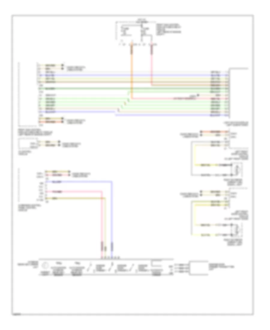
Rear SAM Control Module Wiring Diagram (1 of 2) for Mercedes-Benz CLK320 2005
List of elements for Rear SAM Control Module Wiring Diagram (1 of 2) for Mercedes-Benz CLK320 2005:
- (inside interior of left front seat) driver seat
- Anti-theft system
- Body computer system (front sam control module)
- C10
- C11
- C12
- C13
- C14
- C15
- C16
- C17
- C18
- C19
- C20
- C21
- Can h
- Can l
- Computer data lines system
- Contacting strip
- Convertible
- Coupe
- Defoggers system
- Door locks system
- Engine controls system
- Exterior lights system
- Front passenger seat contacting strip (inside interior of right front seat)
- Instrument cluster
- Interior lights system
- N.c
- N.c.
- Navigation system
- Navigation systen
- Power distribution system
- Power outlet
- Power tops system
- Rear sam control module fuse & relay module (left side of trunk)
- Red
- Seats system
- Signal
- Sound system
- Trunk, tailgate, fuel doors system
- Trunk, tailgate. fuel doors systen
- W6 (at left side of trunk)
- Warning system
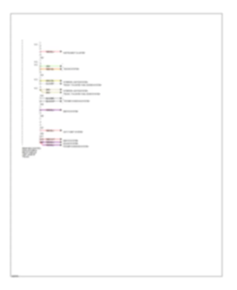
Rear SAM Control Module Wiring Diagram (2 of 2) for Mercedes-Benz CLK320 2005
List of elements for Rear SAM Control Module Wiring Diagram (2 of 2) for Mercedes-Benz CLK320 2005:
- Anti-theft system
- C22
- C23
- C24
- C25
- C26
- C27
- C28
- Instrument cluster
- Interior lights system
- N.c.
- Power windows system
- Rear sam control module fuse & relay module (left side of trunk)
- S17
- S19
- S20
- Seats system
- Sound system
- Trunk, tailgate, fuel door system
- Trunk. tailgate, fuel doors system
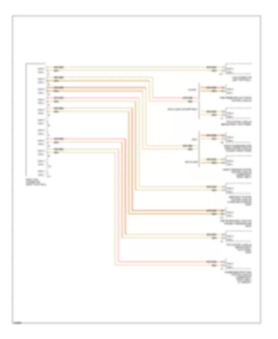
COMPUTER DATA LINES
Data Link Connector Wiring Diagram for Mercedes-Benz CLK320 2005
List of elements for Data Link Connector Wiring Diagram for Mercedes-Benz CLK320 2005:
- C10
- C11
- C20
- C21
- C24
- Command operating, display & control module
- D2b telephone & tele aid transmitter/ receiver (2003)
- Data link connector (at left footwell)
- Di control module (2003)
- Di control module (2004 & 2005)
- Dtr control module (at right kick panel) (2003)
- Electronic selector lever control module (2003)
- Esp/bas control module (in left side of engine compt) (2003)
- Etc control module (behind right kick panel)
- Front sam control module fuse & relay module (right rear of engine compt)
- Fuse 5a
- Hot at all times
- J10
- Left front headlamp unit
- Me-sfi (me) control module (left side of engine)
- Navigation system (2004 & 2005)
- Pnk
- Pnk/red
- Radio
- Radio & navigation unit
- Right front headlamp unit
- W/ auto pilot circuit
- W/ command actuation circuit
- W/ radio circuit
- W16/3 (left front of engine compt)
- W16/5 (left front of engine compt)
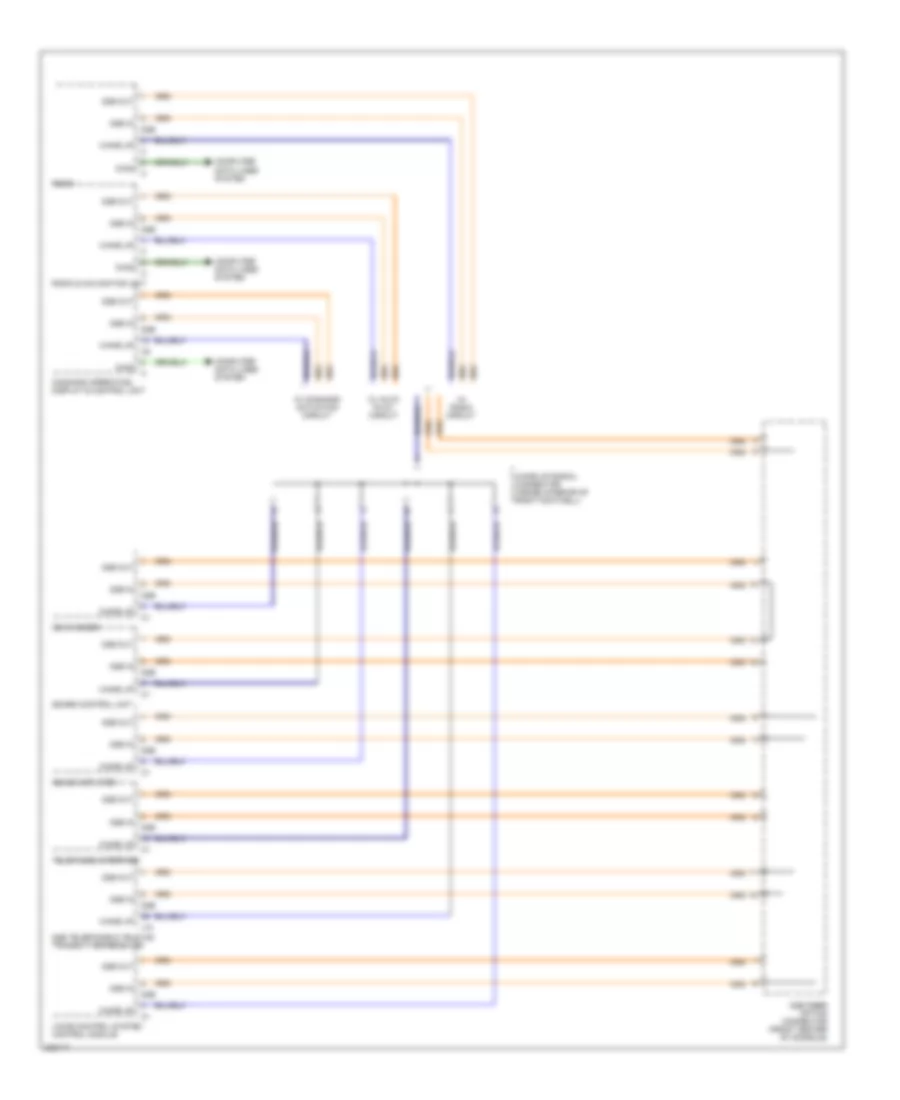
High/Low Bus Wiring Diagram (1 of 4) for Mercedes-Benz CLK320 2005
List of elements for High/Low Bus Wiring Diagram (1 of 4) for Mercedes-Benz CLK320 2005:
- 2004 & 2005
- 2004 & 2005 convertible
- C10
- C11
- Can connector (left footwell)
- Can h
- Can l
- Coupe
- D2b telephone & tele aid transmitter/receiver (2003)
- Front passenger side door control module (in right front door)
- J10
- Passenger front esa control module (under right front seat) (w/ memory)
- Pts control module (behind right kick panel)
- Pts control module (behind right kick panel) (2003)
- Restraint system control module (in center console) (2003)
- Right can connector (right footwell)
- Tire pressure monitoring control module
- Weight sensing system control module (under right front seat)
High/Low Bus Wiring Diagram (2 of 4) for Mercedes-Benz CLK320 2005
List of elements for High/Low Bus Wiring Diagram (2 of 4) for Mercedes-Benz CLK320 2005:
- Aac pushbutton control module (lower center console)
- C10
- C11
- C20
- Can h
- Can l
- Cockpit can connector (left footwell)
- Di control module
- Front sam control module fuse & relay module (left rear of engine compt)
- Instrument cluster
- Lower control field control module (upper center cockpit)
- Overhead control panel control module
- Steering control module (behind steering wheel, in column)
- Upper control panel control module (upper center cockpit)
High/Low Bus Wiring Diagram (3 of 4) for Mercedes-Benz CLK320 2005
List of elements for High/Low Bus Wiring Diagram (3 of 4) for Mercedes-Benz CLK320 2005:
- 2003 convertible
- 2004 & 2005 convertible
- 2004 & 2005 coupe
- C10
- C11
- C18
- Can connector (left footwell)
- Can h
- Can l
- Command operating, display & control unit
- Driver front esa control module (under driver's seat) (w/ memory)
- Front passenger side door control module (in right front door) (2004 & 2005)
- Front sam control module fuse & relay module (left rear of engine compartment)
- Left front door control module (in left front door)
- Overhead control panel control module
- Overhead control panel control module (2003 coupe)
- Pts control module (behind right kick panel) (2004 & 2005 coupe)
- Radio
- Radio & navigation unit
- Rear control module (left side of trunk)
- Rear sam control module fuse & relay module (left side of trunk)
- Restraint system control module (in center console) (2004 & 2005)
- Right can connector (right footwell)
- Tlc control module
- W/ auto pilot circuit
- W/ command actuation circuit
- W/ radio circuit
- Weight sensing system control unit
High/Low Bus Wiring Diagram (4 of 4) for Mercedes-Benz CLK320 2005
List of elements for High/Low Bus Wiring Diagram (4 of 4) for Mercedes-Benz CLK320 2005:
- (left side of engine) me-sfi (me) control module
- 2004 & 2005
- C10
- C11
- Can connector (left footwell)
- Can h
- Can l
- Di control module
- Dtr control module (at right kick panel)
- Electronic selector lever control module
- Esp/bas control module (in left side of engine compt)
- Etc control module (behind right kick panel)
- Instrument cluster
- Steering column module (behind steering wheel)
- W28/1 (at left doorsill)
COOLING FAN
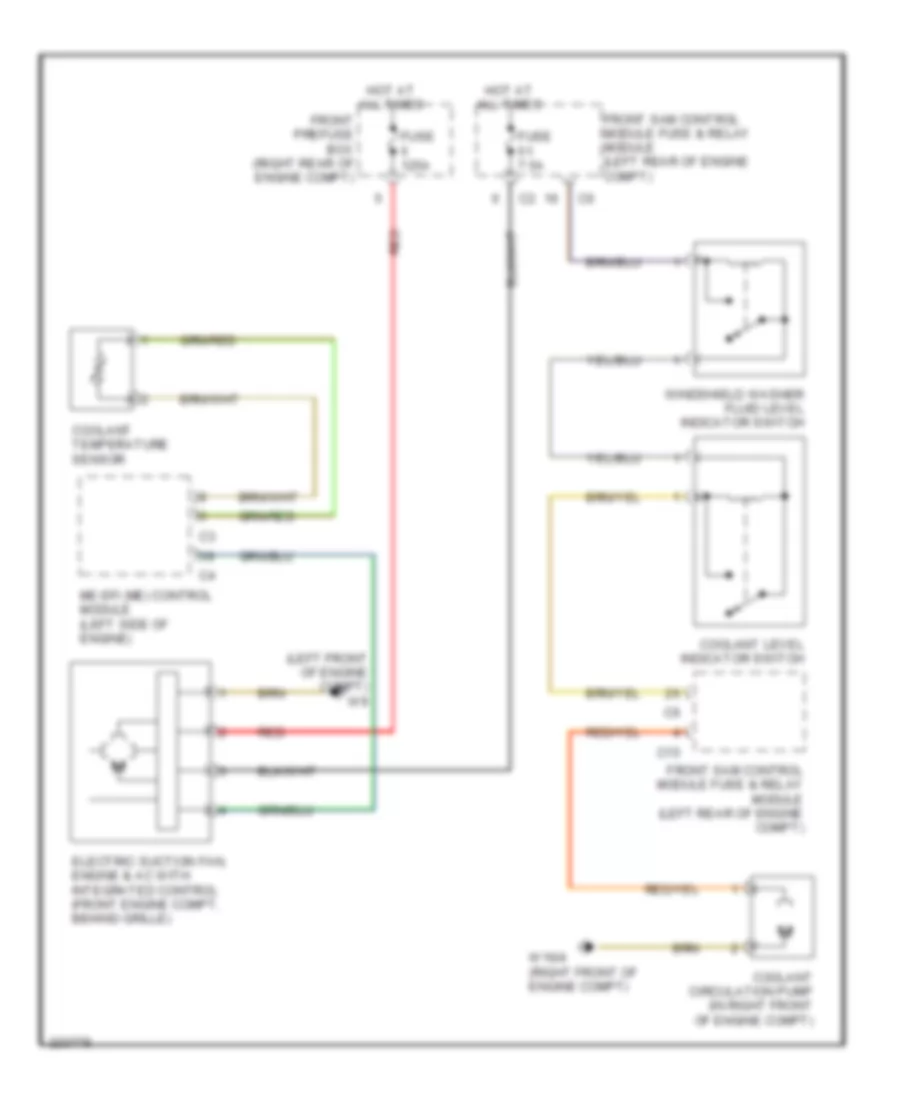
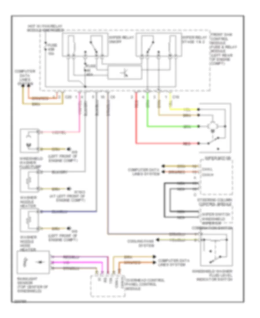
Cooling Fan Wiring Diagram for Mercedes-Benz CLK320 2005
List of elements for Cooling Fan Wiring Diagram for Mercedes-Benz CLK320 2005:
- (left front of engine compt) w9
- C15
- Coolant circulation pump (in right front of engine compt)
- Coolant level indicator switch
- Coolant temperature sensor
- Electric suction fan, engine & ac with integrated control (front engine compt, behind grille)
- Front prefuse box (right rear of engine compt)
- Front sam control module fuse & relay module (left rear of engine compt)
- Fuse 125a
- Fuse 7.5a
- Hot at all times
- Me-sfi (me) control module (left side of engine)
- Red
- W16/4 (right front of engine compt)
- Windshield washer fluid level indicator switch
CRUISE CONTROL
Cruise Control Wiring Diagram for Mercedes-Benz CLK320 2005
List of elements for Cruise Control Wiring Diagram for Mercedes-Benz CLK320 2005:
- Accelerator pedal sensor
- C21
- Can h
- Can l
- Computer data lines system
- Cruise control switch
- Dtr control unit (at right kick panel)
- Front sam control module fuse & relay module (left rear of engine compt)
- Fuse 7.5a
- Hot at all times
- Lower control field control module (upper center cockpit)
- M +
- M -
- Me-sfi (me) control module (left side of engine)
- N.c.
- Nca
- P +
- P -
- Sp1m
- Sp1s
- Sp2m
- Sp2s
- Steering column control module
- Throttle valve actuator (left side of engine compt)
- Upper control panel control module (upper center cockpit)
- Usp1
- W16/4 (right front of engine compt)
DEFOGGERS
Defoggers Wiring Diagram for Mercedes-Benz CLK320 2005
List of elements for Defoggers Wiring Diagram for Mercedes-Benz CLK320 2005:
- Aac pushbutton control module (lewer center console)
- Ambient temperature display temperature sensor
- C10
- C20
- C22
- Cah l
- Can h
- Can l
- Computer data lines system
- Convertible
- Coupe
- Di control module
- Front passenger side door control module (in right front door)
- Front sam control module fuse & relay module (left rear of engine compt)
- Fuse 20a
- Fuse 25a
- Fuse 40a
- Heat
- Heated rear window
- Hs1
- Hs2
- Left exterior heated mirror
- Left front door control module (in left front door)
- Nca
- Overhead control panel control module
- Rear sam control module fuse & relay module (left side of trunk)
- Rear window defroster relay
- Right exterior heated mirror
- Shd (+)
- Shd (-)
- Slide/pop-up roof assembly
- Soft top switch
- W13 (under right side of rear window)
ELECTRONIC POWER STEERING
Electronic Power Steering Wiring Diagram for Mercedes-Benz CLK320 2005
List of elements for Electronic Power Steering Wiring Diagram for Mercedes-Benz CLK320 2005:
- (at right doorsill) w28/2
- 30z
- C19
- Can h
- Can l
- Clock spring contact
- Combination switch
- Computer data lines system
- Cruise control switch
- Di control module
- Electronic selector lever module control module
- Front sam control module fuse & relay module (left rear of engine compt)
- Horns system
- N.c.
- Nca
- Red
- Steering angle sensor
- Steering column adjusment switch
- Steering column control module
- W28/1 (at left doorsill)
ENGINE PERFORMANCE
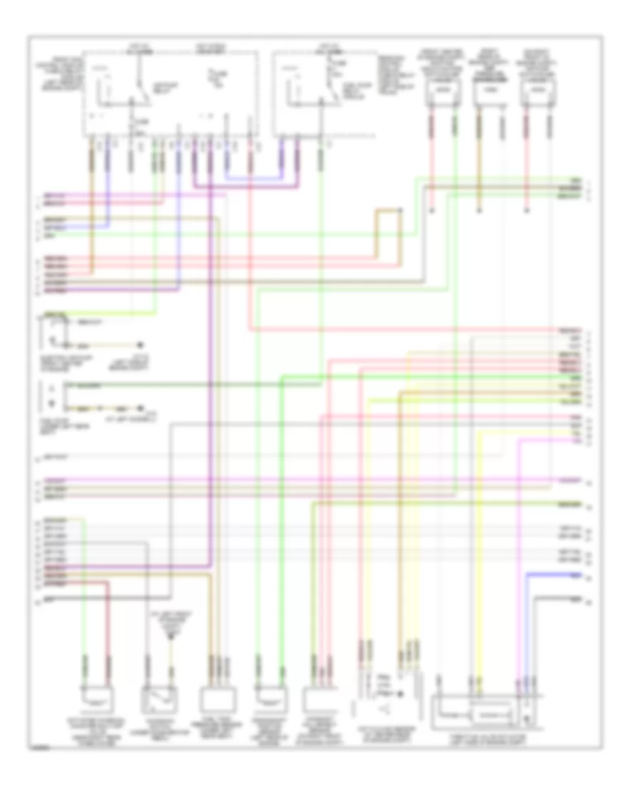
3.2L
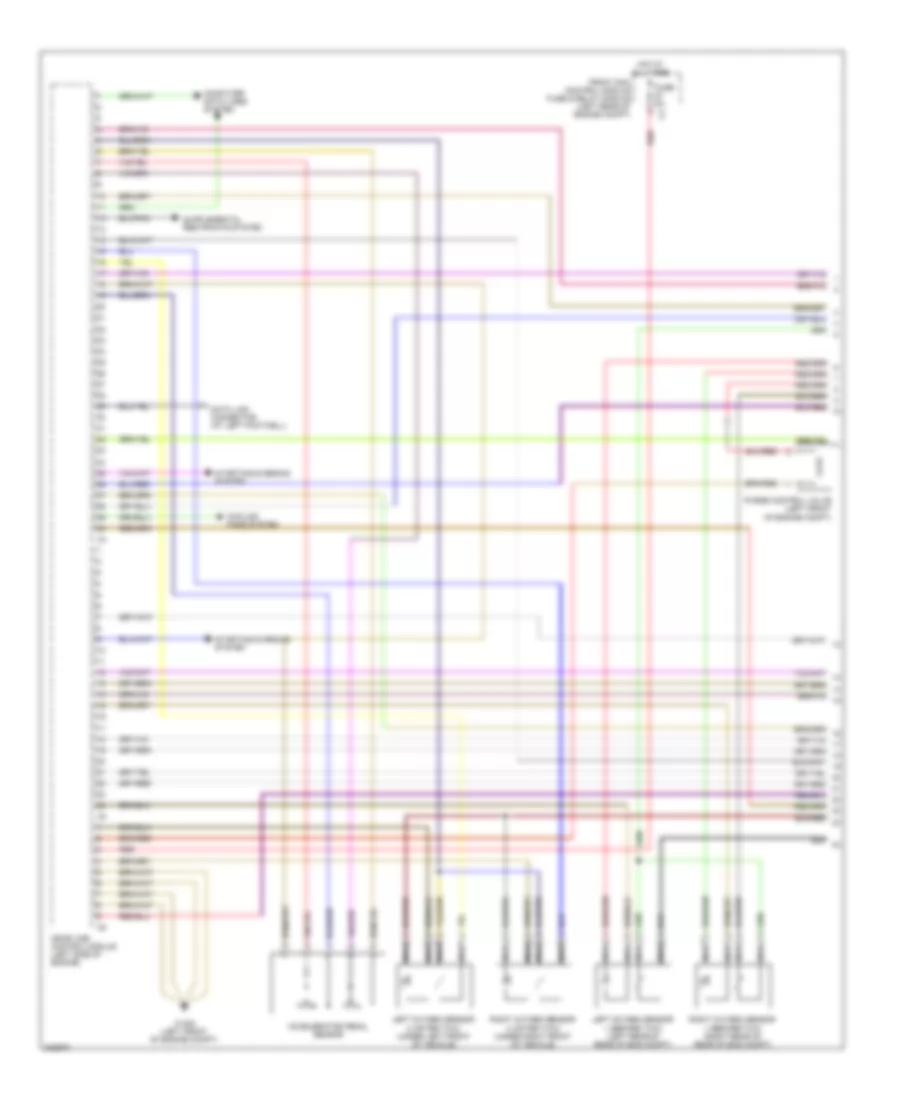
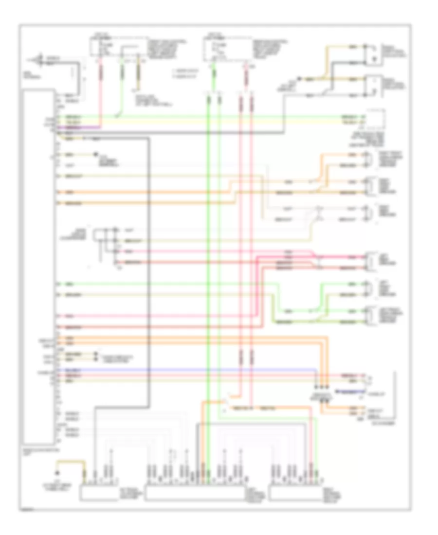
3.2L, Engine Performance Wiring Diagram (1 of 3) for Mercedes-Benz CLK320 2005
List of elements for 3.2L, Engine Performance Wiring Diagram (1 of 3) for Mercedes-Benz CLK320 2005:
- Accelerator pedal sensor
- Computer data lines system
- Cooling fans system
- Data link connector (at left footwell)
- Front sam control module fuse & relay module (left rear of engine compt)
- Fuse 5a
- Hot at all times
- Left oxygen sensor 1 (before twc) (left rear of rear of eng compt)
- Left oxygen sensor 2 (after twc) (under left front of vehicle)
- Me-sfi (me) control module (left side of engine)
- Nca
- Purge control valve (left front of engine compt)
- Red
- Right oxygen sensor 1 (before twc) (right rear of rear of eng compt)
- Right oxygen sensor 2 (after twc) (under right front of vehicle)
- Starting/charging system
- W16/5 (left front of engine compt)
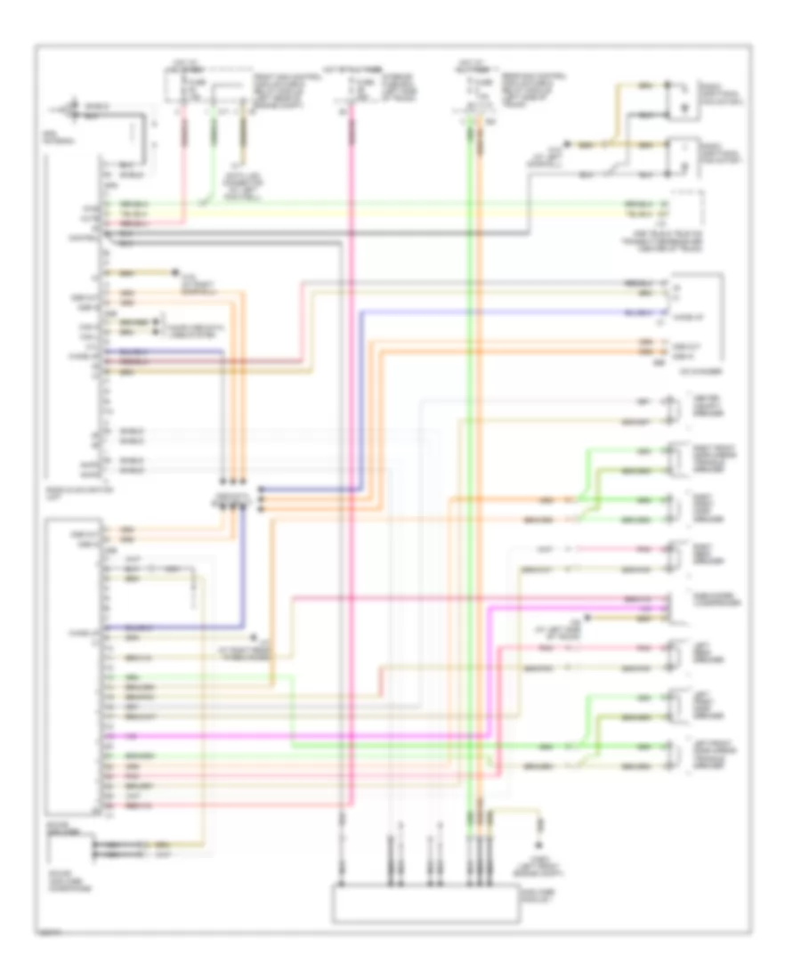
3.2L, Engine Performance Wiring Diagram (2 of 3) for Mercedes-Benz CLK320 2005
List of elements for 3.2L, Engine Performance Wiring Diagram (2 of 3) for Mercedes-Benz CLK320 2005:
- (at left front of engine compt) w16/3
- (front center of engine compt) shifting induction pipe switchover valve
- (on right front of engine compt) air pump switchover valve
- (right rear of engine compt) egr pressure transducer
- Activated charcoal canister shut-off valve (near right rear wheelhouse)
- Air pump relay
- C13
- C17
- Camshaft hall-effect sensor (on right front of engine compt)
- Crankshaft position sensor (left rear of engine)
- Electric air pump (front center of engine)
- Front sam control module fuse & relay module (left rear of engine compt)
- Fuel pump (under left rear seat)
- Fuel pump relay module
- Fuel tank pressure sensor (under left rear seat)
- Fuse 15a
- Fuse 30a
- Fuse 40a
- Hot at all times
- Hot film maf sensor (at center rear of engine compt)
- Hot in run or start
- Kickdown switch (under accelerator pedal)
- Pnk
- Rear sam control module fuse & relay module (left side of trunk)
- Throttle valve actuator (left side of engine compt)
- W11/3 (left side of engine compt)
- W18 (at left doorsill)
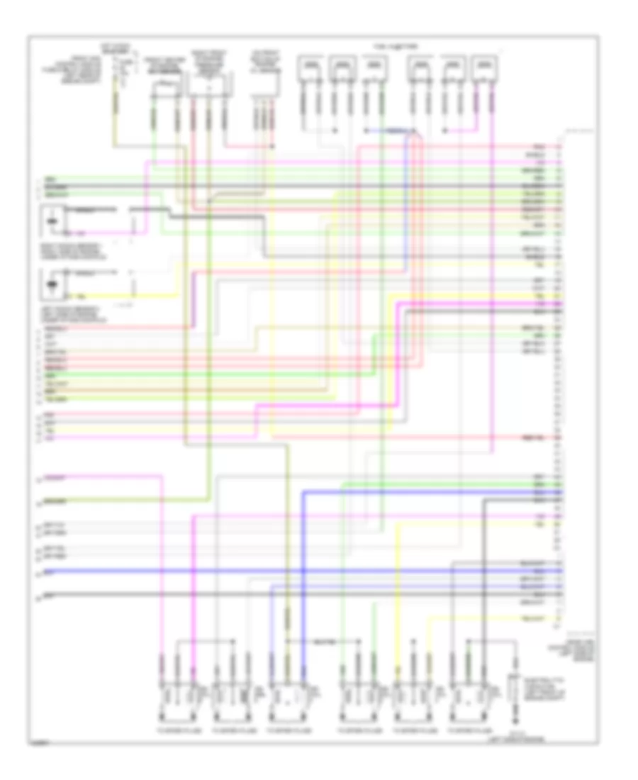
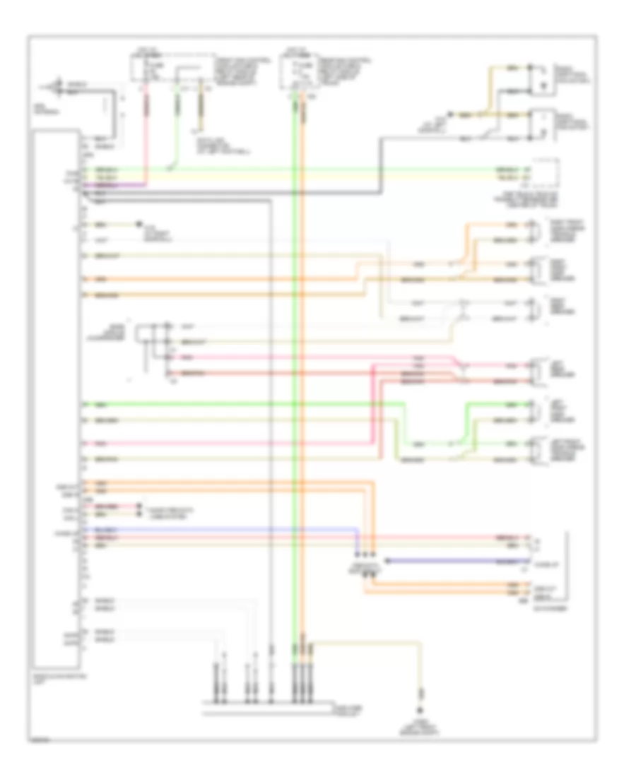
3.2L, Engine Performance Wiring Diagram (3 of 3) for Mercedes-Benz CLK320 2005
List of elements for 3.2L, Engine Performance Wiring Diagram (3 of 3) for Mercedes-Benz CLK320 2005:
- (front center of engine) ect sensor
- (on front bottom of engine) oil sensor
- (right front of engine) pressure sensor
- C17
- Electrolytic capacitor (left front of engine compt)
- Front sam control module fuse & relay module (left rear of engine compt)
- Fuel injectors
- Fuse 15a
- Hot in run or start
- Ign coil
- Ign coil coil
- Left knock sensor 2 (left side of engine, under intake manifold)
- Me-sfi (me) control module (left side of engine)
- Pnk
- Right knock sensor 1 (right side of engine, under intake manifold)
- Shield
- To spark plugs
- W11/3 (left side of engine)
EXTERIOR LIGHTS
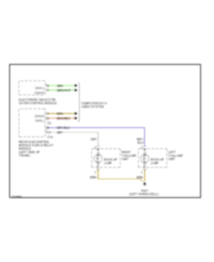
Back-up Lamps Wiring Diagram for Mercedes-Benz CLK320 2005
List of elements for Back-up Lamps Wiring Diagram for Mercedes-Benz CLK320 2005:
- Back-up lamp
- C14
- Can h
- Can l
- Computer data lines system
- Electronic selector lever control module
- Left taillamp unit
- Rear sam control module fuse & relay module (left side of trunk)
- Right taillamp unit
- W6/1 (left wheelwell)
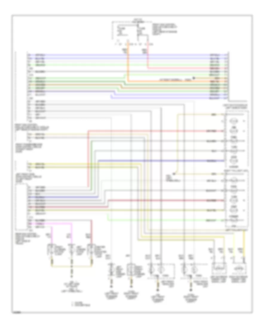
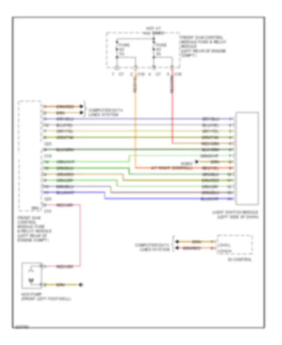
Exterior Lamps Wiring Diagram for Mercedes-Benz CLK320 2005
List of elements for Exterior Lamps Wiring Diagram for Mercedes-Benz CLK320 2005:
- (at right doorsill)
- C14
- C19
- C20
- C21
- Center high mounted stop lamp
- Coupe convertible
- Fog
- Front passenger side door control module (in right front door)
- Front sam control module fuse & relay module (left rear of engine compt)
- Fuse 5a
- Hot at all times
- Left exterior mirror turn signal lamp
- Left front headlamp unit
- Left front side door control module (in left front door)
- Left front side marker lamp
- Left license plate lamp
- Left taillight unit
- Light switch module (left side of dash)
- Marker
- Park
- Rear sam control module fuse & relay module (left side of trunk)
- Red
- Red/
- Right exterior mirror turn signal lamp
- Right front headlamp unit
- Right front side marker lamp
- Right license plate lamp
- Right taillight unit
- Stop
- Turn
- W16/4 (right front of engine compt)
- W28/2
- W6 (at left side of trunk) w6/1 (left wheelwell)
- W6/1 (left wheelwell)
- W9 (left front of engine compt)
GROUND DISTRIBUTION
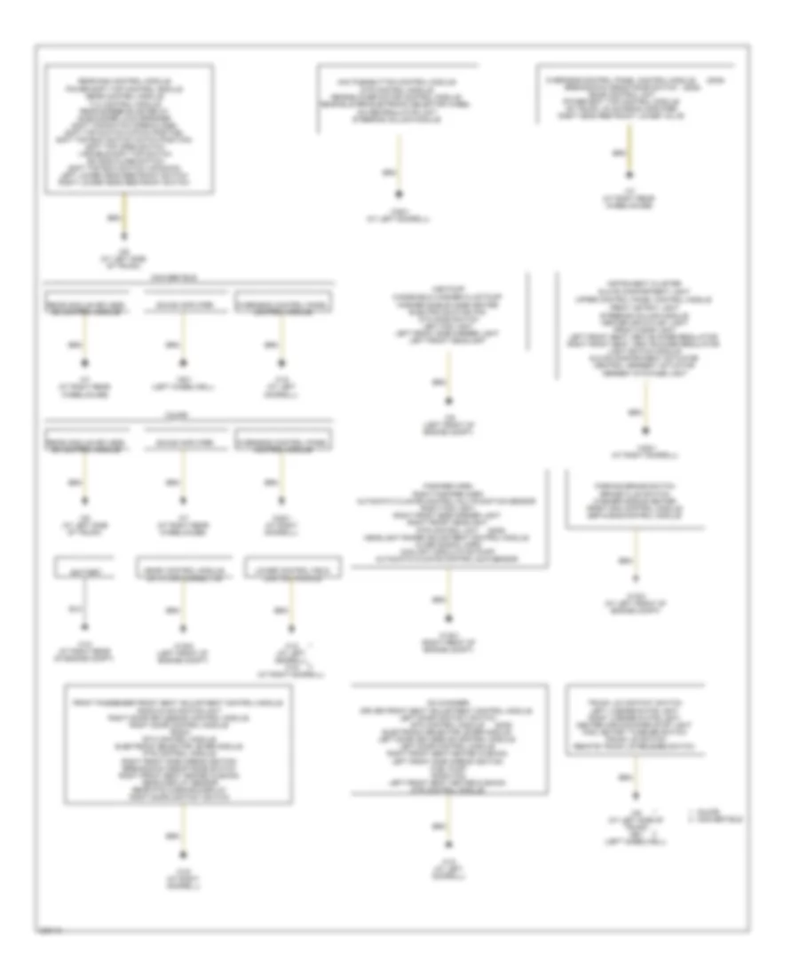
Ground Distribution Wiring Diagram for Mercedes-Benz CLK320 2005
List of elements for Ground Distribution Wiring Diagram for Mercedes-Benz CLK320 2005:
- (2005)
- Aac pushbutton control module dtr control module rear blower motor control module rear blower electronic selector wheel a/c recirculation unit steering column module
- Battery
- Brake fluid switch washer nozzle heater front sam control module esp & bas control module
- Cd changer
- Convertible
- Coupe
- Driver front seat adjustment control module left door contact switch etc control module electronic selector lever module left door keyless go control module left door control module right front seat heated cushion left front side airbag ignition fuel pump radio fan left front seat heated cushion dtr control module
- Fanfare horn
- Front astray light
- Front passenger front seat adjustment control module
- Glove compartment light
- Hcs pump
- Instrument cluster
- Left license plate light right license plate light center high-mounted stop light paml rotary tumbler switch trunk lid switch remote trunk lid release switch
- Lower control field control module
- Me-sfi control module data link connector
- Overhead control panel control module
- Overhead control panel control module breakdown assistance switch sdar control unit power soft top control module am trunk lid antenna amplifier right head restraint lower valve
- Parking brake switch
- Power soft top control module rear control module tlc control module rear screen blind relay subwoofer loud speaker soft top switch (open/close) soft top switch (catch position) soft top bow switch (catch position) soft top open switch variable soft top switch ski bag close switch soft top bow switch (up/down) left lower head restraint switch right lower head restraint switch
- Radio & navigation unit right door keyless go control module right door control module radio etc control module electronic selector lever module pts control module right front side airbag ignition breakdown assistance switch right front seat heated cushion gear display sensor rear pts warning display right door contact switch
- Rear module keyless go control module
- Rear sam control module
- Right fanfare horn automatic climate control multifunction sensor right fog light right front side marker light right front headlight dtr control unit headlight range adjustment control module alarm signal horn coolant circulation pump automatic climate control sun sensor
- Sound amplifier
- Steering column module center air outlet light front cigar light left front seat vent blower regulator right front seat vent blower regulator light switch module glove compartment actuator central armrest actuator armrest stowage light
- Trunk lid contact switch
- Upper control panel control module
- W10 (at right rear of engine compt)
- W16/3 (at left front of engine compt)
- W16/4 (right front of engine compt)
- W16/5 (left front of engine compt)
- W18 (at left doorsill)
- W18 (at left doorsill) w19 (at right doorsill)
- W19 (at right doorsill)
- W28/1 (at left doorsill)
- W28/1 (at right doorsill)
- W6 (at left side of trunk)
- W6 (at left side of trunk) w6/1 (left wheelwell)
- W6/1 (left wheelwell)
- W7 (at right rear wheelhouse)
- W9 (left front of engine compt)
- Windshield washer fluid pump washer nozzle hose heater electric suction fan ata hood switch left fog light left front side marker light left front headlight
HEADLIGHTS
Headlights Wiring Diagram, with Xenon Lamps for Mercedes-Benz CLK320 2005
List of elements for Headlights Wiring Diagram, with Xenon Lamps for Mercedes-Benz CLK320 2005:
- (left front of engine compt) w9
- C20
- C24
- Can h
- Can l
- Combination switch
- Computer data lines system
- Front axle sensor
- Front sam control module fuse & relay module (left rear of engine compt)
- Fuse f51 7.5a
- High
- High beam indicator
- Hot at all times
- Instrument cluster
- L/r turn sig sw headlamp flasher/ high beam sw
- Left fog lamp
- Left front headlight unit
- Low
- Nca
- Park
- Rear axle sensor
- Right fog lamp
- Right front headlight unit
- Steering column control module
- Turn
- W16/4 (right front of engine compt)
- W9 (left front of engine compt)
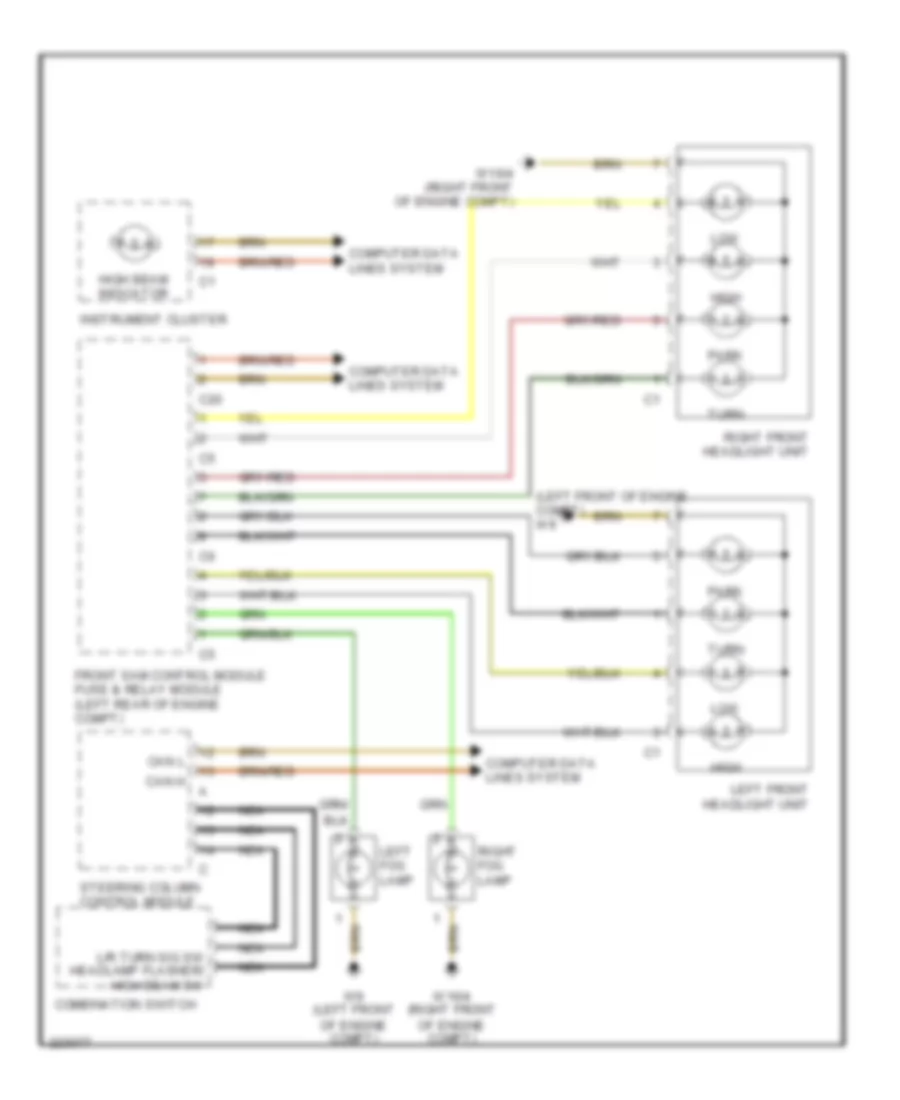
Headlights Wiring Diagram, without Xenon Lamps for Mercedes-Benz CLK320 2005
List of elements for Headlights Wiring Diagram, without Xenon Lamps for Mercedes-Benz CLK320 2005:
- (left front of engine compt) w9
- C20
- Can h
- Can l
- Combination switch
- Computer data lines system
- Front sam control module fuse & relay module (left rear of engine compt)
- High
- High beam indicator
- Instrument cluster
- L/r turn sig sw headlamp flasher/ high beam sw
- Left fog lamp
- Left front headlight unit
- Low
- Nca
- Park
- Right fog lamp
- Right front headlight unit
- Steering column control module
- Turn
- W16/4 (right front of engine compt)
- W9 (left front of engine compt)
HORN
Horn Wiring Diagram for Mercedes-Benz CLK320 2005
List of elements for Horn Wiring Diagram for Mercedes-Benz CLK320 2005:
- C10
- C20
- Can h
- Can l
- Computer data lines system
- Di control module
- Fan relay module
- Fanfare horns
- Fanfare horns switch
- Front sam control module fuse & relay module (left rear of engine compt)
- Fuse 43a 15a
- Left multifunction steering wheel pushbutton group
- Nca
- Red
- Right fanfare horns
- Right multifunction steering wheel pushbutton group
- Steering column control module
- W16/4 (right front of engine compt)
INSTRUMENT CLUSTER
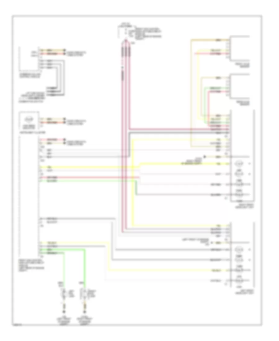
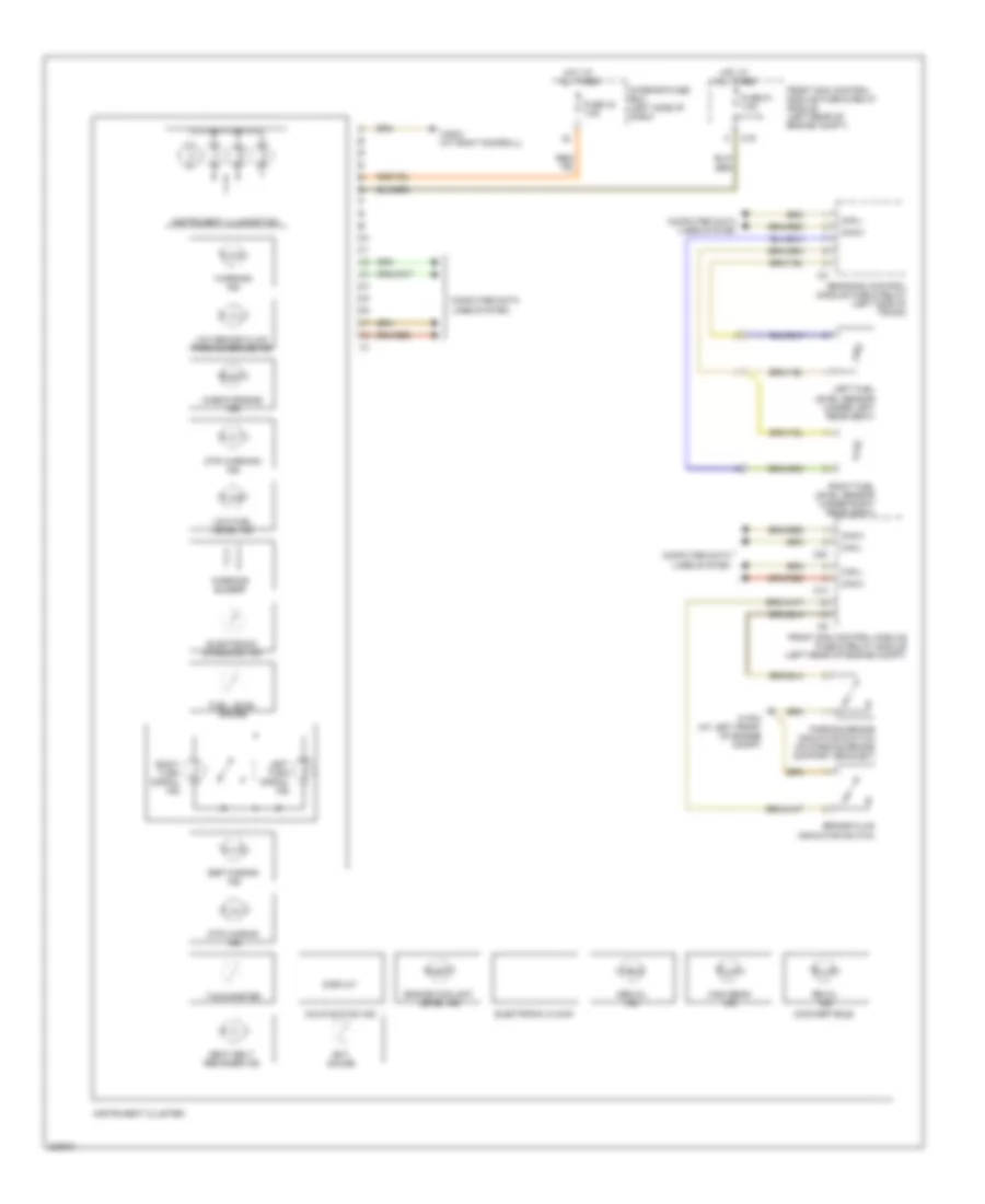
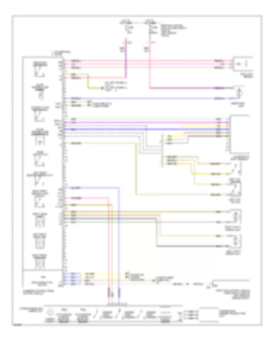
Instrument Cluster Wiring Diagram for Mercedes-Benz CLK320 2005
List of elements for Instrument Cluster Wiring Diagram for Mercedes-Benz CLK320 2005:
- (convertible)
- Abs mil ind
- Brake fluid indicator switch
- C10
- C19
- C20
- Can h
- Can l
- Check engine ind
- Computer data lines system
- Display
- Dtr waring ind
- Dtr warning ind
- Ect gauge
- Electronic clock
- Electronic speedometer
- Engine coolant level ind
- Esp waring ind
- Front sam control module fuse & relay module (left rear of engine compt)
- Fuel level gauge
- Fuse 42 7.5a
- Fuse 51 7.5a
- High beam ind
- Hot at all times
- Instrument cluster
- Instrument illumination
- Interior fuse box (left side of dash)
- Left fuel level sensor (under left rear seat)
- Left turn signal ind
- Low brake fluid/ parking brake ind
- Low fuel level ind
- Malfunction ind
- Parking brake indicator switch (on parking brake support bracket)
- Rb mil ind
- Rear sam control module fuse & relay (left side of trunk)
- Right fuel level sensor (under right rear seat)
- Right turn signal ind
- Seat belt reminder ind
- Tachometer
- W16/3 (at left front of engine compt)
- W28/2 (at right doorsill)
- Warning buzzer
- Warning ind
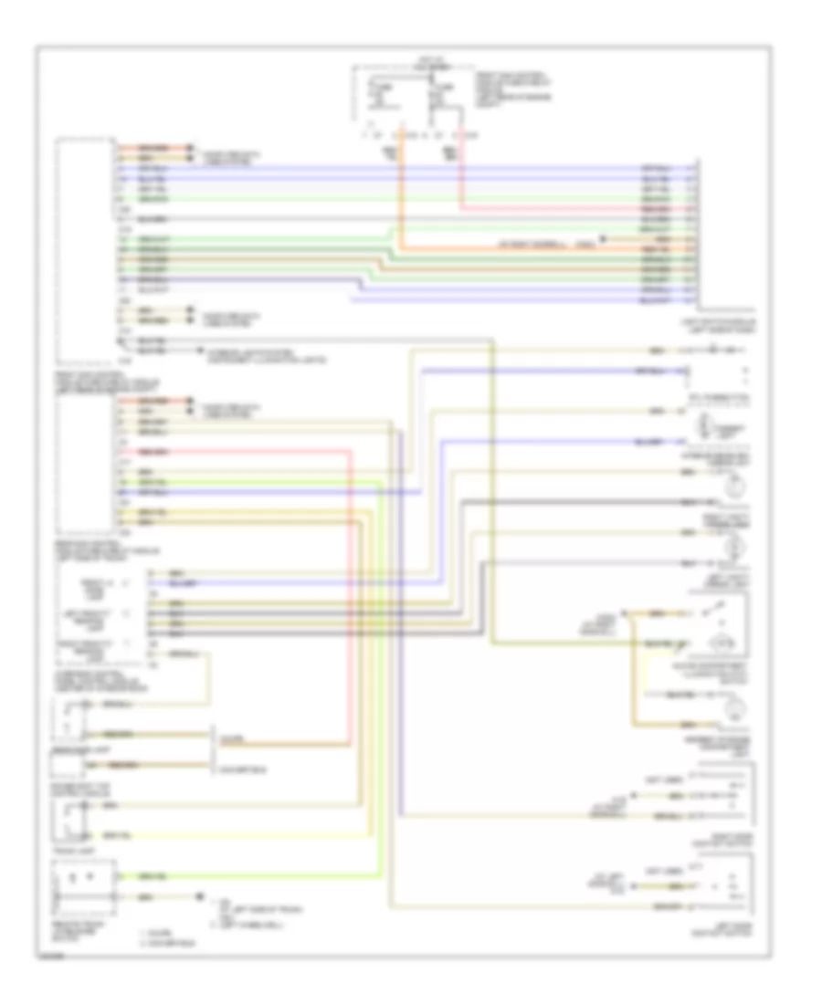
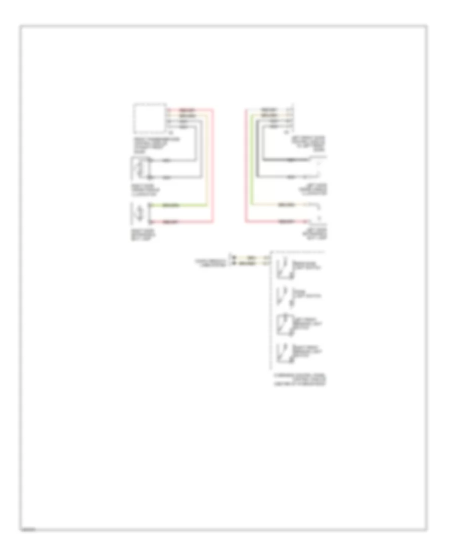
Overhead Console Wiring Diagram for Mercedes-Benz CLK320 2005
List of elements for Overhead Console Wiring Diagram for Mercedes-Benz CLK320 2005:
- (at left doorsill) w18 (at left doorsill) w28/1
- (at right rear wheelwell) w7
- 15r
- 31 ais
- 58d
- Ais
- Ambient light
- Auto dimming interior rearview sensor
- Automatic dimming mirror
- C17
- C22
- C25
- Can h
- Can l
- Computer data lines system
- Convertible coupe
- Dome lamp switch
- Front dome lamp
- Front sam control module fuse & relay module (left rear of engine compt)
- Fuse 20a
- Fuse 25a
- Garage door opener 1
- Garage door opener 2
- Garage door opener 3
- Garage door opener transmitter unit
- Hot at all times
- Hs1
- Hs2
- In-car temperature sensor
- In-car temperature sensor motor
- Interior rearview mirror unit
- Left front dome lamp
- Left front reading lamp switch
- Left vanity mirror light
- N.c.
- Navigation system (2003 & 2004)
- Nca
- Overhead control panel control module
- Pnk/red
- Rain/light sensor
- Rear dome lamp switch
- Rear dome light
- Rear sam control module fuse & relay module (left side of trunk)
- Right front dome lamp
- Right front reading lamp switch
- Right vanity mirror light
- Shd (+)
- Shd (-)
- Slide/pop-up roof assembly
- Sliding/tilting roof switch
- Soft top switch
- Sos pushbutton switch
INTERIOR LIGHTS
Courtesy Lamps Wiring Diagram (1 of 2) for Mercedes-Benz CLK320 2005
List of elements for Courtesy Lamps Wiring Diagram (1 of 2) for Mercedes-Benz CLK320 2005:
- (at left door sill) w18
- (at right doorsill)
- (not used)
- Ambient light
- Armrest storage compartment light
- C10
- C17
- C19
- C20
- C21
- C24
- Computer data lines system
- Convertible
- Coupe
- Front dome lamp
- Front sam control module fuse & relay module (left rear of engine compt)
- Fuse 5a
- Glove compartment illumination with switch
- Hot at all times
- Interior lights system (instrument illumination lights)
- Interior rearview mirror unit
- Left door contact switch
- Left front reading lamp
- Left vanity mirror light
- Light switch module (left side of dash)
- Overhead control panel control module (center of interior roof)
- Power soft top control module
- Rear dome lamp
- Rear sam control module fuse & relay module (left side of trunk)
- Remote trunk lid release switch
- Right door contact switch
- Right front reading lamp
- Right vanity mirror light
- Rtl pushbutton
- Trunk lamp
- W19 (at right door sill)
- W28/2
- W28/2 (at right door sill)
- W6 (at left side of trunk) w6/1 (left wheelwell)
Courtesy Lamps Wiring Diagram (2 of 2) for Mercedes-Benz CLK320 2005
List of elements for Courtesy Lamps Wiring Diagram (2 of 2) for Mercedes-Benz CLK320 2005:
- Computer data lines system
- Dome light switch
- Front passenger side control module (in right front door)
- Left door entrance & exit lamp
- Left door inside handle illumination
- Left front door control module (in left front door)
- Left front reading light switch
- Nca
- Overhead control panel control module (center of interior roof)
- Rear dome light switch
- Right door entrance & exit lamp
- Right door inside handle illumination
- Right front reading light switch
Instrument Illumination Wiring Diagram (1 of 2) for Mercedes-Benz CLK320 2005
List of elements for Instrument Illumination Wiring Diagram (1 of 2) for Mercedes-Benz CLK320 2005:
- (-)
- (at right doorsill)
- 58d
- C19
- C20
- C25
- Center air outlet illumination
- Computer data lines system
- Front ashtray light
- Front cigar lighter
- Front passenger power window switch
- Front passenger side door control module (in right front door)
- Front sam control module fuse & relay module (left rear of engine compt)
- Fuse 5a
- Hot at all times
- Instrument cluster
- Instrument illumination
- Interior light system (courtesy lights)
- Left rear power window switch
- Light switch module (left side of dash)
- Nca
- Power soft top control module (left front of trunk)
- Rear control module (left side of trunk)
- Right rear power window switch
- Soft top control switch (2003)
- W28/2
- W28/2 (at right door sill)
Instrument Illumination Wiring Diagram (2 of 2) for Mercedes-Benz CLK320 2005
List of elements for Instrument Illumination Wiring Diagram (2 of 2) for Mercedes-Benz CLK320 2005:
- (front center of trunk) tele aid system control module
- C12
- C17
- Emergency call system control module (front center of trunk) (2005)
- Info led
- J10
- Led
- Mb-info & breakdown assistance switch (2003 & 2004)
- Mb-info & breakdown assistance switch (2005)
- Overhead control panel control module
- Rear pts warning display (coupe)
- Rear sam control module fuse & relay module (left side of trunk)
- Sos pushbutton switch (2005)
- W19 (at right doorsill)
- W7 (at right rear wheelhouse)
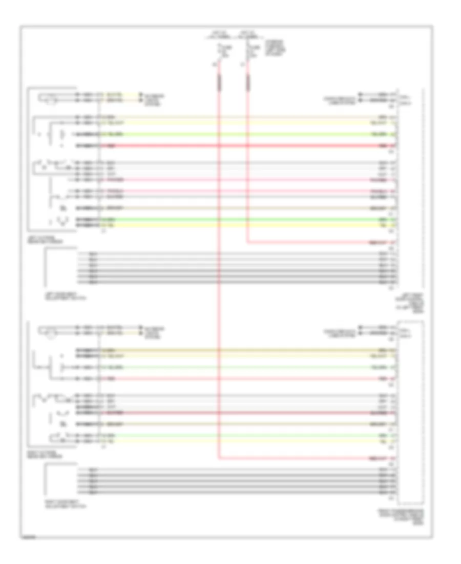
MEMORY SYSTEMS
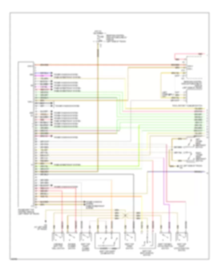
Driver"s Memory Seat Wiring Diagram for Mercedes-Benz CLK320 2005
List of elements for Driver"s Memory Seat Wiring Diagram for Mercedes-Benz CLK320 2005:
- (2003)
- (2003) (2004 & 2005)
- (2004 & 2005)
- Backrest motor
- C10
- C11
- Can h
- Can l
- Computer data lines system
- Driver front seat adjustment control module
- Driver seat backrest release microswitch
- Driver seat height release microswitch
- Forward/ back longitudinal adjustment motor
- Forward/ back motor
- Front up/down motor
- Fuse 27 fuse 29 30a
- Height adjustment up/down motor
- Hh (+)
- Hh (-)
- Hot at all times
- Hv (+)
- Hv (-)
- Interior fuse box (left side of dash)
- Left door seat adjustment switch
- Left front door control module (in left front door)
- Lk (+)
- Lk (-)
- Lv (+)
- Lv (-)
- Mhh (+)
- Mhh (-)
- Mhv (+)
- Mhv (-)
- Mlk (+)
- Mlk (-)
- Mlv (+)
- Mlv (-)
- Rear up/down motor
- Red
- W18 (at left doorsill)
Memory Mirrors Wiring Diagram for Mercedes-Benz CLK320 2005
List of elements for Memory Mirrors Wiring Diagram for Mercedes-Benz CLK320 2005:
- Can h
- Can l
- Computer data lines system
- Exterior lights system
- Front passenger side door control module (in right front door)
- Fuse 30a
- Hot at all times
- Interior fuse box (left side of dash)
- Left door seat adjustment switch
- Left front door control module (in left front door)
- Left outside rearview mirror
- Nca
- Pnk/red
- Red
- Right door seat adjustment switch
- Right outside rearview mirror
Passenger"s Memory Seat Wiring Diagram for Mercedes-Benz CLK320 2005
List of elements for Passenger"s Memory Seat Wiring Diagram for Mercedes-Benz CLK320 2005:
- Backrest motor
- C10
- C11
- Can h
- Can l
- Computer data lines system
- Driver front seat adjustment control module
- Driver seat backrest release microswitch
- Driver seat height release microswitch
- Forward/ back motor
- Front passenger side door control module (in right front door)
- Front up/down motor
- Fuse 30a
- Hh (+)
- Hh (-)
- Hot at all times
- Hv (+)
- Hv (-)
- Interior fuse box (left side of dash)
- Lk (+)
- Lk (-)
- Lv (+)
- Lv (-)
- Mhh (+)
- Mhh (-)
- Mhv (+)
- Mhv (-)
- Mlk (+)
- Mlk (-)
- Mlv (+)
- Mlv (-)
- Rear up/down motor
- Red
- Right door seat adjustment switch
- W19 (at right doorsill)
NAVIGATION
Parktronic Wiring Diagram, Convertible for Mercedes-Benz CLK320 2005
List of elements for Parktronic Wiring Diagram, Convertible for Mercedes-Benz CLK320 2005:
- (+) sf
- (+) sr
- (-) sf
- (-) sr
- 15r
- C10
- C12
- Can h
- Can l
- Center pts warning display
- Computer data lines system
- Front bumper pts sensor unit
- Fuse 5a
- Hot at circuit 15 relay 1
- Interior fuse box (left side of dash)
- Left center sensor
- Left inner sensor
- Left outer sensor
- N.c.
- Pts control module (behind right kick panel)
- Rear bumper pts sensor unit
- Rear pts warning display
- Right center sensor
- Right inner sensor
- Right outer sensor
- S1 f
- S10 r
- S2 f
- S3 f
- S4 f
- S5 f
- S6 f
- S7 r
- S8 r
- S9 r
- W f (+)
- W f (-)
- W f (data)
- W r (+)
- W r (-)
- W r (data)
- W19 (at right doorsill)
Parktronic Wiring Diagram, Except Convertible for Mercedes-Benz CLK320 2005
List of elements for Parktronic Wiring Diagram, Except Convertible for Mercedes-Benz CLK320 2005:
- (+) sf
- (+) sr
- (-) sf
- (-) sr
- 15r
- C10
- C12
- C17
- Can h
- Can l
- Center pts warning display
- Computer data lines system
- Front bumper pts sensor unit
- Fuse 5a
- Hot at circuit 15 relay 1
- Interior fuse box (left side of dash)
- Left center sensor
- Left inner sensor
- Left outer sensor
- N.c.
- Overhead control panel control module
- Pts control module (behind right kick panel)
- Rear bumper pts sensor unit
- Rear pts warning display
- Rear sam control module fuse & relay module (left side of trunk)
- Right center sensor
- Right inner sensor
- Right outer sensor
- S1 f
- S10 r
- S2 f
- S3 f
- S4 f
- S5 f
- S6 f
- S7 r
- S8 r
- S9 r
- W f (+)
- W f (-)
- W f (data)
- W r (+)
- W r (-)
- W r (data)
- W19 (at right doorsill)
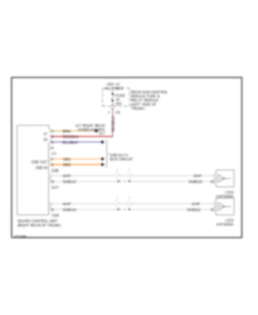
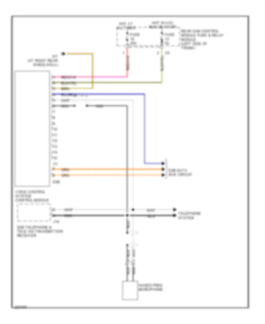
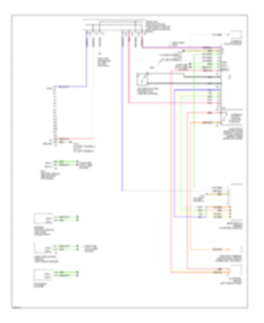
Tele Aid Wiring Diagram, with D2B Data Bus for Mercedes-Benz CLK320 2005
List of elements for Tele Aid Wiring Diagram, with D2B Data Bus for Mercedes-Benz CLK320 2005:
- (at right rear wheelhouse) w7
- 15r
- 58d
- Airbag sig
- Aux. antenna
- C11
- C21
- C23
- C25
- C26
- Can h
- Can l
- Computer data lines system
- Ctel antenna
- D2b
- D2b data bus circuit
- D2b in
- D2b out
- Diag
- Frequency switchover control module
- Front sam control module fuse & relay module (left rear of engine compt)
- Fuse 7.5a
- Gps
- Gps antenna
- Hot at all times
- Info led
- Info sw
- Interior fuse box (left side of dash)
- J10
- Led
- Left front emergency call speaker
- Mb-info & breakdown assistance switch
- Mic +
- Mic -
- Mute
- Navigation system (voice activation circuit)
- Nca
- Pnk
- Radio & navigation unit
- Radio/command operating, display & control unit
- Rap sw
- Rear sam control module fuse & relay module (left side of trunk)
- Rf sw
- Right front emergency call speaker
- Sos led
- Sos pushbutton switch (in overhead control panel control module)
- Sos sw
- Speaker +
- Speaker -
- Tele aid spare antenna
- Tele aid system control module (front center of trunk)
- Telephone interface
- Unlock
- W/ auto pilot circuit
- W/ radio circuit/ command actuation circuit
- W19 (at right doorsill)
- W7 (at right rear wheelhouse)
- Wake up
Tele Aid Wiring Diagram, without D2B Data Bus for Mercedes-Benz CLK320 2005
List of elements for Tele Aid Wiring Diagram, without D2B Data Bus for Mercedes-Benz CLK320 2005:
- (at right rear wheelhouse) w7
- 15r
- 58d
- Airbag sig
- Aux. antenna
- C11
- C21
- C23
- C25
- C26
- Can h
- Can l
- Computer data lines system
- Ctel antenna
- Diag
- Frequency switchover control module
- Front sam control module fuse & relay module (left rear of engine compt)
- Fuse 7.5a
- Gps
- Gps antenna
- Hot at all times
- Info led
- Info sw
- Interior fuse box (left side of dash)
- J10
- Led
- Left front emergency call speaker
- Mb-info & breakdown assistance switch
- Mic +
- Mic -
- Mute
- Navigation system (voice activation circuit)
- Nca
- Pnk
- Radio & navigation unit
- Radio/command operating, display & control unit
- Rap sw
- Rear sam control module fuse & relay module (left side of trunk)
- Rf sw
- Right front emergency call speaker
- Sos led
- Sos pushbutton switch (in overhead control panel control module)
- Sos sw
- Speaker +
- Speaker -
- Tele aid spare antenna
- Tele aid system & d2b telephone transmitter/receiver control module (front center of trunk)
- Telephone interface
- Unlock
- W/ auto pilot circuit
- W/ radio circuit/ command actuation circuit
- W19 (at right doorsill)
- W7 (at right rear wheelhouse)
PASSIVE RESTRAINTS
Passive Restraints Wiring Diagram for Mercedes-Benz CLK320 2005
List of elements for Passive Restraints Wiring Diagram for Mercedes-Benz CLK320 2005:
- Left sbe (left rear interior compt) (convertible)
- Left sbe (left rear interior compt) (coupe)
- Nca
- Power soft top control module (left front of trunk)
- Rear control module (left side of trunk)
- Red
- Right sbe (right rear interior compt) (convertible)
- Right sbe (right rear interior compt) (coupe)
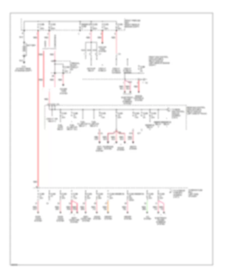
POWER DISTRIBUTION
Power Distribution Wiring Diagram (1 of 3) for Mercedes-Benz CLK320 2005
List of elements for Power Distribution Wiring Diagram (1 of 3) for Mercedes-Benz CLK320 2005:
- A/c system
- Air pump relay
- Anti- theft system
- Battery
- Body computer system
- C19
- Circuit 15 relay
- Circuit 15r relay 2
- Circuit 87 relay (chassis)
- Circuit 87 relay (engine)
- Convertible
- Cooling fans system
- Coupe
- Door locks system
- Electronic power steering system
- Engine controls system
- Front prefuse box (right rear of engine compt)
- Front sam control module fuse & relay module (left rear of engine compt)
- Fuel filler cap relay 1& 2
- Fuel filler cap relay 1
- Fuel filler cap relay 2
- Fuel pump relay
- Fuse
- Fuse (reserve) 30a
- Fuse (reserve) 30a (2005)
- Fuse 10a
- Fuse 125a
- Fuse 200a
- Fuse 20a
- Fuse 25a
- Fuse 30a
- Fuse 40a
- Fuse 5a
- Fuse 60a
- Fuse 7.5a
- Interior fuse box (left side of dash)
- Memory system
- Nca
- Power tops system
- Rear sam control module fuse & relay module (left side of trunk)
- Red
- Red/ pnk
- Reserve fuse
- Reserve relay
- S17
- S19
- Seats system
- Sound system
- Telephone system
- Terminal block (circuit 30)
- To interior fuse box (diagram 2 of 3)
- To rear sam control module (diagram 2 of 3)
- W10 (at right rear of engine compt)
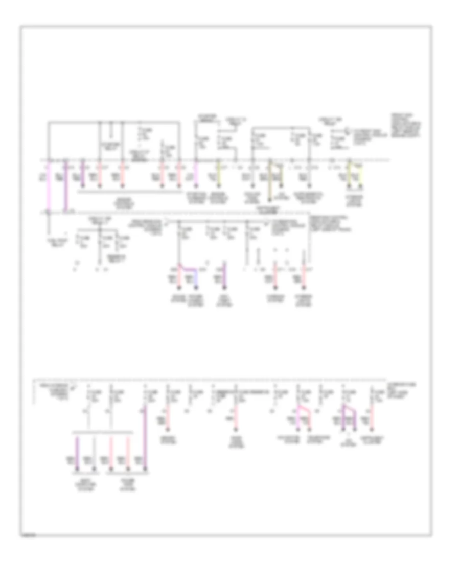
Power Distribution Wiring Diagram (2 of 3) for Mercedes-Benz CLK320 2005
List of elements for Power Distribution Wiring Diagram (2 of 3) for Mercedes-Benz CLK320 2005:
- A/c system
- Anti- theft system
- Body computer system
- C12
- C13
- C14
- C16
- C17
- C19
- C28
- Circuit 15 relay
- Circuit 15r relay
- Circuit 15r relay 2
- Circuit 87 relay (engine)
- Cooling fans system
- Door locks system
- Engine controls system
- From interior b fuse box (diagram 1 of 3)
- From rear sam a control module (diagram 1 of 3)
- Front sam control module fuse & relay module (left rear of engine compt)
- Fuel pump relay
- Fuse
- Fuse (reserve) 25a
- Fuse 15a
- Fuse 20a
- Fuse 25a
- Fuse 30a
- Fuse 5a
- Fuse 7.5a
- Instrument cluster
- Interior fuse box (left side of dash)
- Interior lights system
- Memory system
- Navigation system
- Power tops system
- Power window system
- Rear sam control module fuse & relay module (left side of trunk)
- Red
- Reserve fuse
- Reserve relay 1
- S18
- S20
- Sound system
- Starter relay
- Starting/ charging system
- Telephone system
- To front sam control module (diagram 3 of 3)
- To rear sam control module (diagram 3 of 3)
- Warning system
Power Distribution Wiring Diagram (3 of 3) for Mercedes-Benz CLK320 2005
List of elements for Power Distribution Wiring Diagram (3 of 3) for Mercedes-Benz CLK320 2005:
- Anti-lock brakes system
- Body computer system
- C11
- C12
- C19
- C20
- C21
- C22
- C23
- C24
- Circuit 15r relay
- Circuit 15r relay 1
- Computer data lines system
- Cruise control system
- Defogger system
- Fan relay
- From front sam c control module (diagram 2 of 3)
- From front sam e control module (diagram 3 of 3)
- From rear sam d control module (diagram 2 of 3)
- Front sam control module fuse & relay module (left rear of engine compt)
- Fuse 15a
- Fuse 20a
- Fuse 25a
- Fuse 40a
- Fuse 43a 15a
- Fuse 43b 15a
- Fuse 50a
- Fuse 5a
- Fuse 7.5a
- Headlights system
- Interior lights system
- Navigation system
- Power outlet
- Rear sam control module fuse & relay module (left side of trunk)
- Rear window defroster relay
- Red
- Seats system
- Seq pump control relay
- Sound system
- To front sam control module (diagram 3 of 3)
- Wiper relay on/off
- Wiper relay stage 1& 2
POWER DOOR LOCKS
Power Door Locks Wiring Diagram (1 of 2) for Mercedes-Benz CLK320 2005
List of elements for Power Door Locks Wiring Diagram (1 of 2) for Mercedes-Benz CLK320 2005:
- (at left door sill) w18
- (at right door sill) w19
- 58d
- Can h
- Can l
- Closed
- Computer data lines system
- Front passenger side door control module (in right front door)
- Fuse 25a
- Fuse 30a
- Hot at all times
- Interior fuse box (left side of dash)
- Left door cl motor
- Left door entrance & exit lamp
- Left door inside handle illumination
- Left front door control module (in left front door)
- Left front ir reciever
- Nca
- Open
- Power locking switch
- Red
- Right door cl motor
- Right door entrance & exit lamp
- Right door inside handle illumination
- Right front ir reciever
- Rtl pushbutton
- Tlc control module (coupe)
- Trunk lid motor
- Trunk lid opening angle dectection sensor
- W6 (at left side of trunk)
Power Door Locks Wiring Diagram (2 of 2) for Mercedes-Benz CLK320 2005
List of elements for Power Door Locks Wiring Diagram (2 of 2) for Mercedes-Benz CLK320 2005:
- (at left door sill) w18
- (at right door sill) w19
- (not used)
- 58d
- C13
- C21
- Can h
- Can l
- Computer data lines system
- Convertible
- Coupe
- Fuel filler cap polarity change relay 1
- Fuel filler cap polarity change relay 2
- Fuel filler flap cl motor
- Fuse 10a
- Glove compartment cl electromagnetic actuator
- Left door contact switch
- Rear sam control module fuse & relay module (left side of trunk)
- Right door contact switch
- Rtl pushbutton (convertible)
- W28/2 (at right doorsill)
POWER MIRRORS
Automatic Day/Night Mirror Wiring Diagram for Mercedes-Benz CLK320 2005
List of elements for Automatic Day/Night Mirror Wiring Diagram for Mercedes-Benz CLK320 2005:
- 15r
- 31 ais
- 58d
- Ais
- Ambient light
- Auto dimming interior rearview sensor
- Automatic dimming mirror
- C10
- C19
- C20
- Can h
- Can l
- Computer data lines system
- Di control module
- Front sam control module fuse & relay module (left rear of engine compt)
- Fuse 5a
- Garage door opener 1
- Garage door opener 2
- Garage door opener 3
- Garage door opener transmitter unit
- Hot at all times
- Interior rearview mirror unit
- Left front door control module (in left front door)
- Light switch module (left side of dash)
- N.c.
- Nca
- Overhead control panel control module
- Pnk/red
- Right exterior mirror turn signal light
- W28/2 (at right doorsill)
POWER SEATS
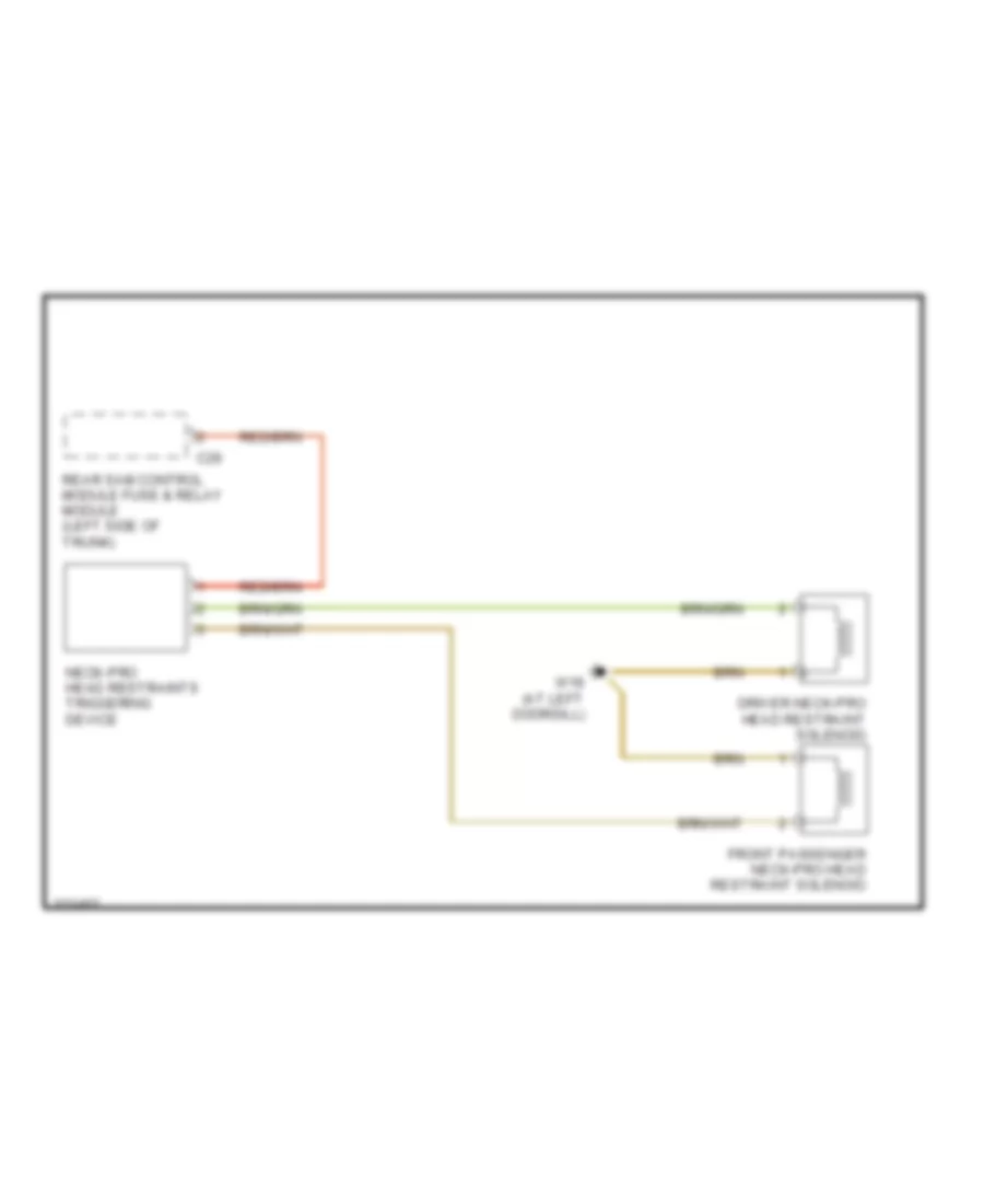
Headrest Wiring Diagram for Mercedes-Benz CLK320 2005
List of elements for Headrest Wiring Diagram for Mercedes-Benz CLK320 2005:
- C26
- Driver neck-pro head restraint solenoid
- Front passenger neck-pro head restraint solenoid
- Neck-pro head restraints triggering device
- Rear sam control module fuse & relay module (left side of trunk)
- W18 (at left doorsill)
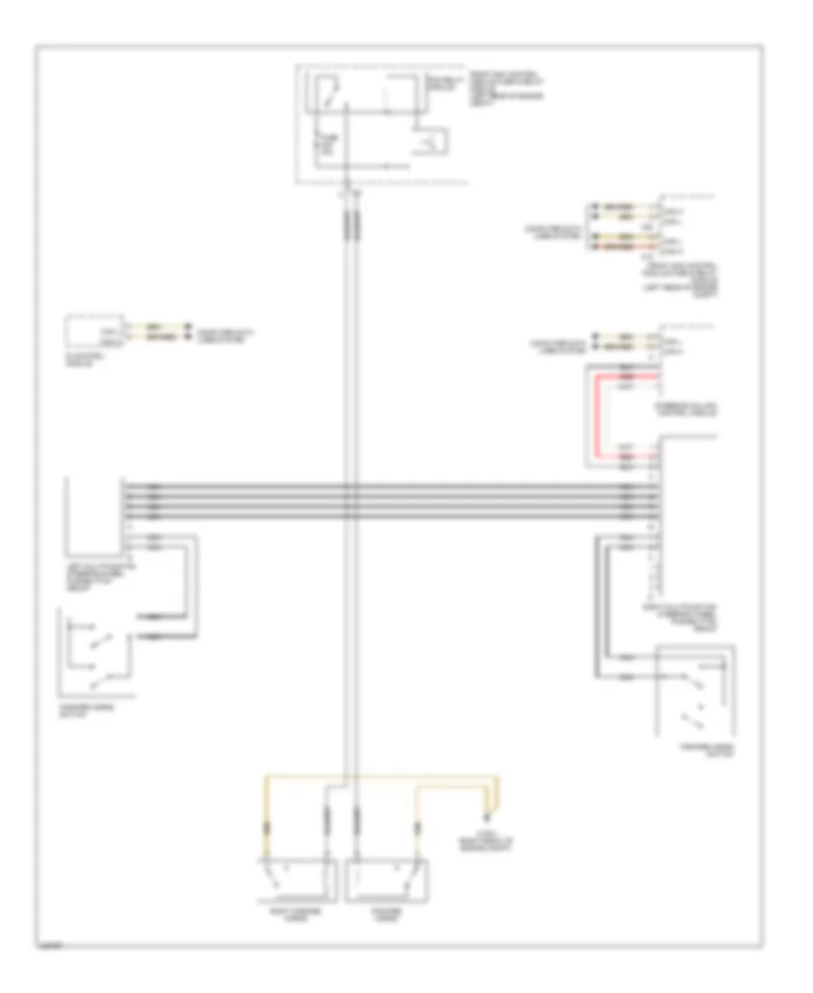
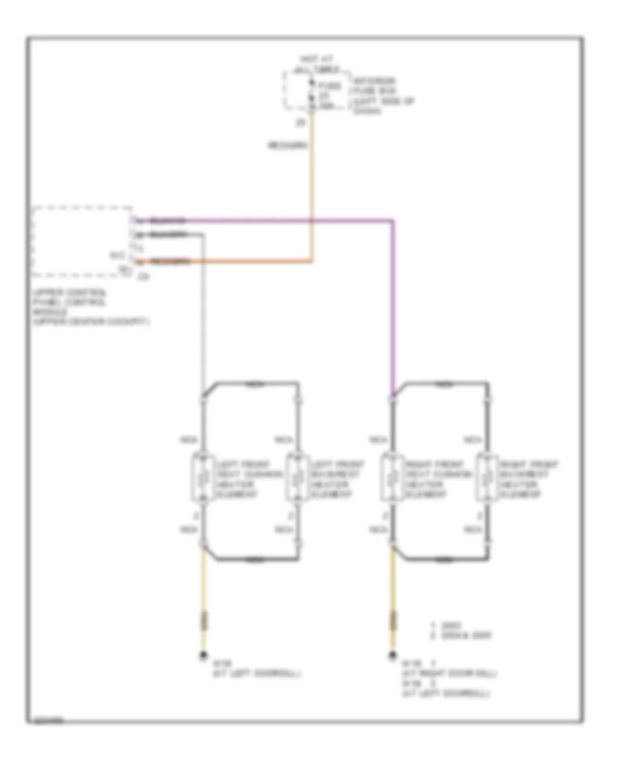
Heated Seats Wiring Diagram for Mercedes-Benz CLK320 2005
List of elements for Heated Seats Wiring Diagram for Mercedes-Benz CLK320 2005:
- 2004 & 2005
- Fuse 30a
- Hot at all times
- Interior fuse box (left side of dash)
- Left front backrest heater element
- Left front seat cushion heater element
- N.c.
- Nca
- Right front backrest heater element
- Right front seat cushion heater element
- Upper control panel control module (upper center cockpit)
- W18 (at left doorsill)
- W19 (at right door sill) w18 (at left doorsill)
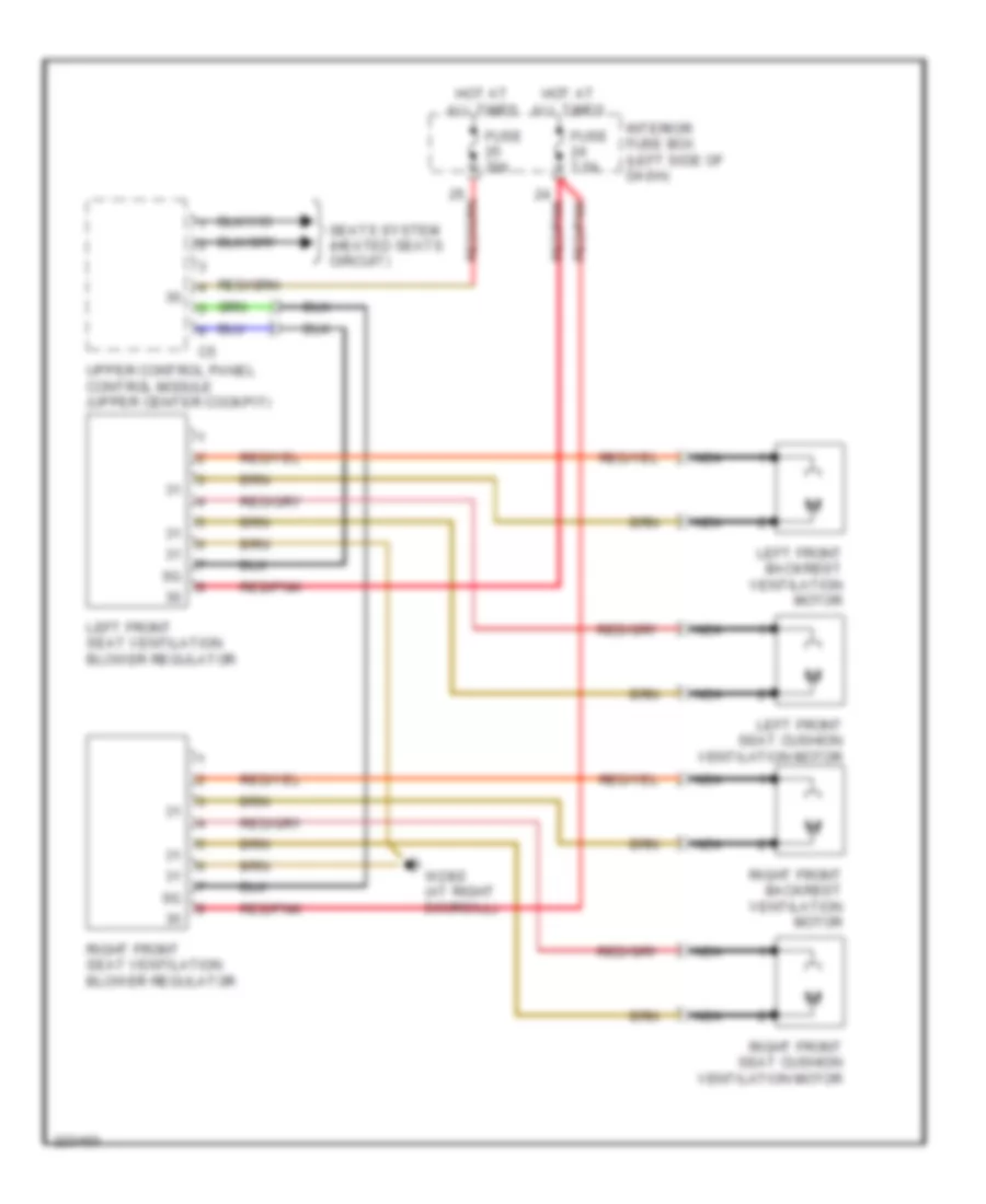
Seat Ventilation Wiring Diagram for Mercedes-Benz CLK320 2005
List of elements for Seat Ventilation Wiring Diagram for Mercedes-Benz CLK320 2005:
- Fuse 30a
- Fuse 7.5a
- Hot at all times
- Interior fuse box (left side of dash)
- Left front seat ventilation blower regulator
- Left front backrest ventilation motor
- Left front seat cushion ventilation motor
- Nca
- Red/pnk
- Right front seat ventilation blower regulator
- Right front backrest ventilation motor
- Right front seat cushion ventilation motor
- Seats system (heated seats circuit)
- Upper control panel control module (upper center cockpit)
- W28/2 (at right doorsill)
POWER TOP/SUNROOF
Convertible Top Wiring Diagram (1 of 2) for Mercedes-Benz CLK320 2005
List of elements for Convertible Top Wiring Diagram (1 of 2) for Mercedes-Benz CLK320 2005:
- (at left side of trunk) w6
- (left wheelwell) w6/1
- 58d
- C17
- C18
- C21
- Can h
- Can l
- Closed
- Fuse 20a
- Hot at all times
- Left lower head restraint switch
- Open
- Passive restraint system
- Pawl rotary tumbler switch
- Power soft top control module (left front of trunk)
- Power windows system
- Power windows system passive restraint system
- Rear sam control module fuse & relay module (left side of trunk)
- Red
- Right lower head restraint switch
- Ski-bag "closed" switch
- Soft top "open" switch
- Soft top bow catch position switch
- Soft top bow up/down switch
- Soft top compt catch position switch
- Soft top compt closed switch
- Soft top compt cover switch
- Variable soft top well switch
- W6 (at left side of trunk)
Convertible Top Wiring Diagram (2 of 2) for Mercedes-Benz CLK320 2005
List of elements for Convertible Top Wiring Diagram (2 of 2) for Mercedes-Benz CLK320 2005:
- Can h
- Can l
- Front prefuse box (right rear of engine compt)
- Fuse 200a
- Fuse 20a
- Fuse 30a
- Fuse 40a
- Hot at all times
- Interior fuse box (left side of dash)
- Left head restraint lower valve
- Left rollover module deployment solenoid
- Lower control field control module (upper center cockpit)
- Nca
- Passive restraints system
- Power locking switch (remote trunk locking)
- Power soft top control module (left front of trunk)
- Power windows system
- Red
- Right head restraint lower valve
- Right rollover module deployment solenoid
- Signal
- Soft top mechanism hydraulic unit
- Terminal block (circuit 30)
- Trunk lid opening angle detection sensor (remote trunk locking)
- Upper control panel control module (upper center cockpit)
- W14 (left rear of trunk)
- W6 (at left side of trunk)
- W7 (at right rear wheelhouse)
Glass Roof Wiring Diagram for Mercedes-Benz CLK320 2005
List of elements for Glass Roof Wiring Diagram for Mercedes-Benz CLK320 2005:
- (at left doorsill) w28/1
- Aac pushbutton control module (lower center console)
- Can h
- Can l
- Can l
- Computer data lines system
- Di control module
- Front passenger side door control module (in right front door)
- Front sam control module fuse & relay module (right rear of engine compt)
- Left front door control module (in left front door)
- Left front ir receiver (in left front door)
- Overhead control panel control module
- Right front ir receiver (in right front door))
- Slide/pop-up roof assembly
POWER WINDOWS
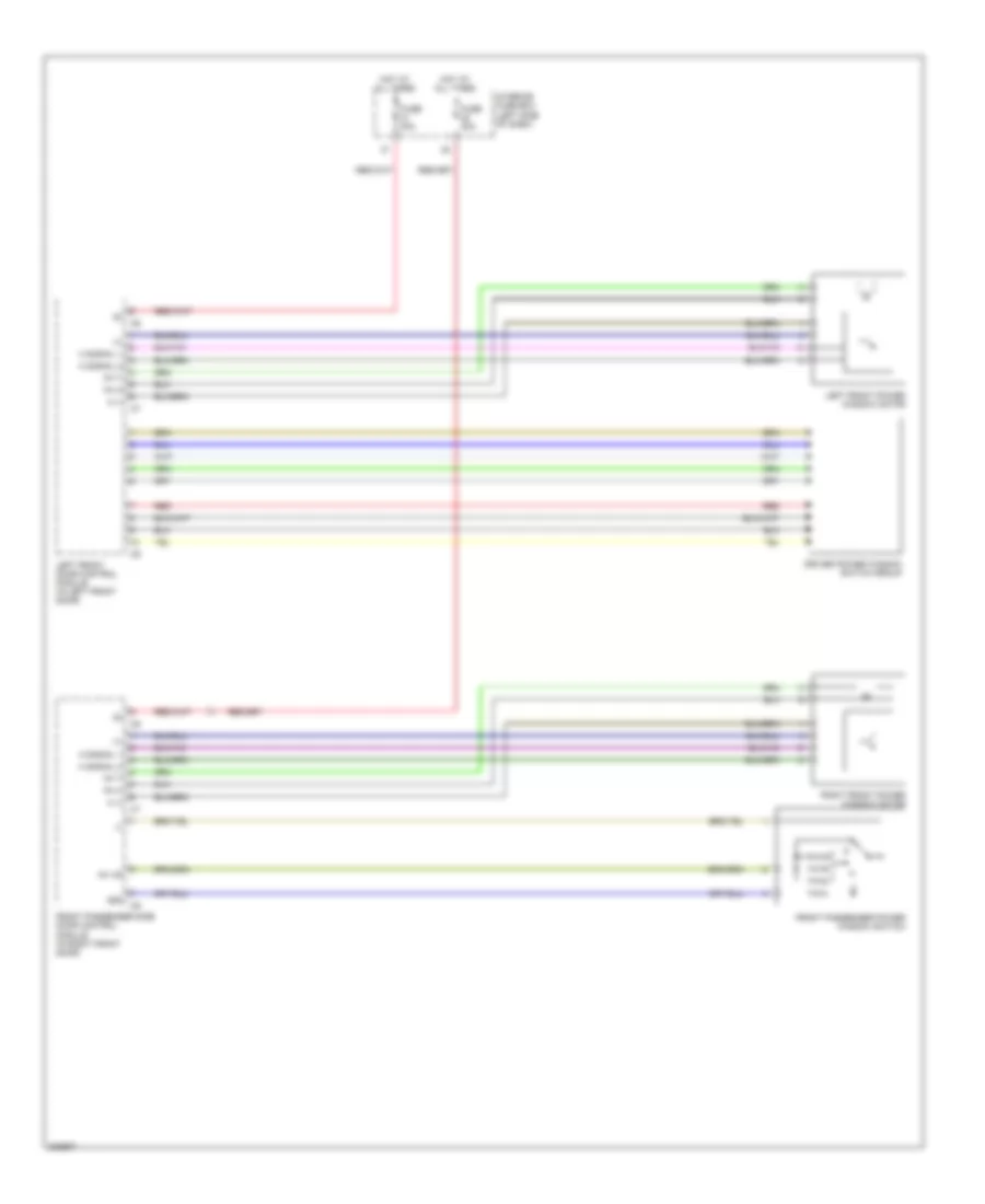
Power Windows Wiring Diagram, Convertible (1 of 2) for Mercedes-Benz CLK320 2005
List of elements for Power Windows Wiring Diagram, Convertible (1 of 2) for Mercedes-Benz CLK320 2005:
- (+)
- (-)
- 58d
- Driver power window switch group
- Fh h
- Fh t
- Fh vr
- Front passenger power window switch
- Front passenger side door control module (in right front door)
- Fuse 30a
- H (-)
- H signal 1
- H signal 2
- Hot at all times
- Interior fuse box (left side of dash)
- Left front door control module (in left front door)
- Left front power window motor
- N.c.
- Red
- Right front power window motor
Power Windows Wiring Diagram, Convertible (2 of 2) for Mercedes-Benz CLK320 2005
List of elements for Power Windows Wiring Diagram, Convertible (2 of 2) for Mercedes-Benz CLK320 2005:
- 58d
- Left rear power window motor
- Left rear power window switch
- Power soft top control module (left front of trunk)
- Right rear power window motor
- Right rear power window switch
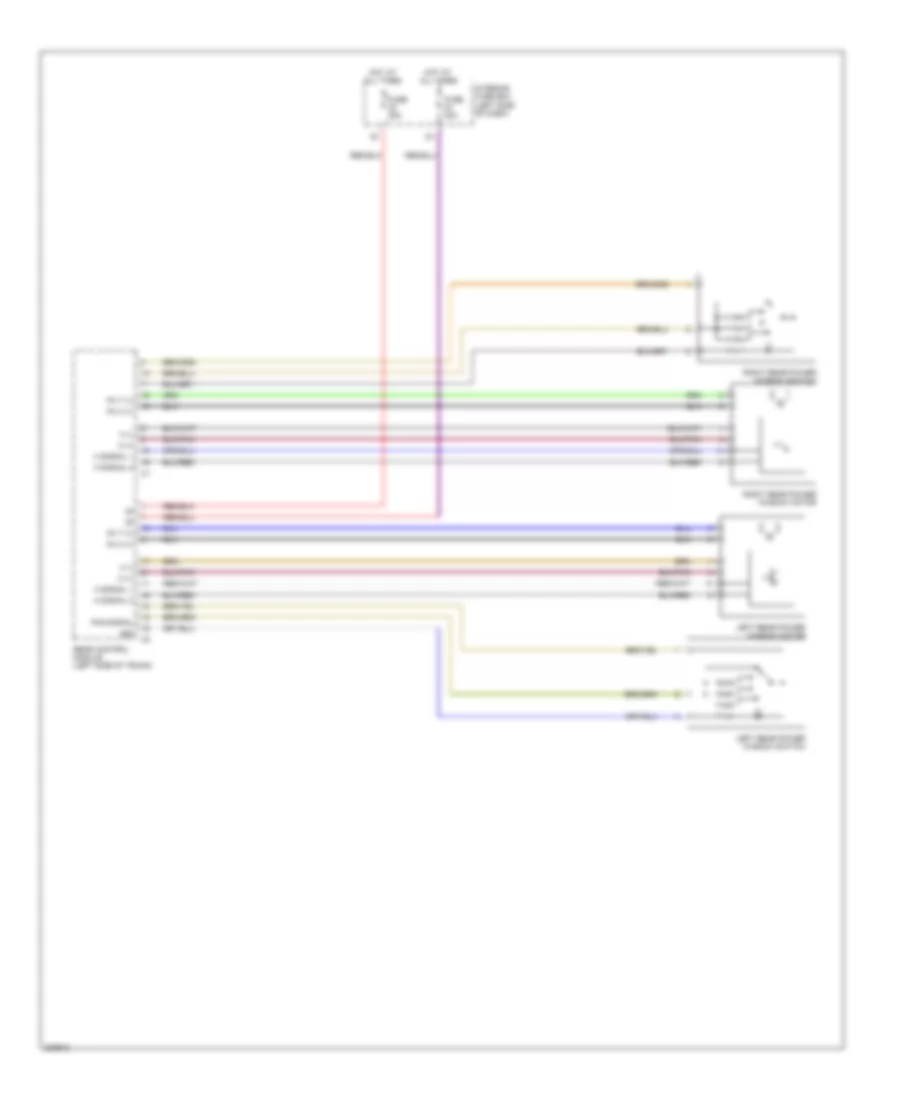
Power Windows Wiring Diagram, Except Convertible (1 of 2) for Mercedes-Benz CLK320 2005
List of elements for Power Windows Wiring Diagram, Except Convertible (1 of 2) for Mercedes-Benz CLK320 2005:
- (+)
- (-)
- 58d
- Driver power window switch group
- Fh h
- Fh t
- Fh vr
- Front passenger power window switch
- Front passenger side door control module (in right front door)
- Fuse 30a
- H (-)
- H signal 1
- H signal 2
- Hot at all times
- Interior fuse box (left side of dash)
- Left front door control module (in left front door)
- Left front power window motor
- Red
- Right front power window motor
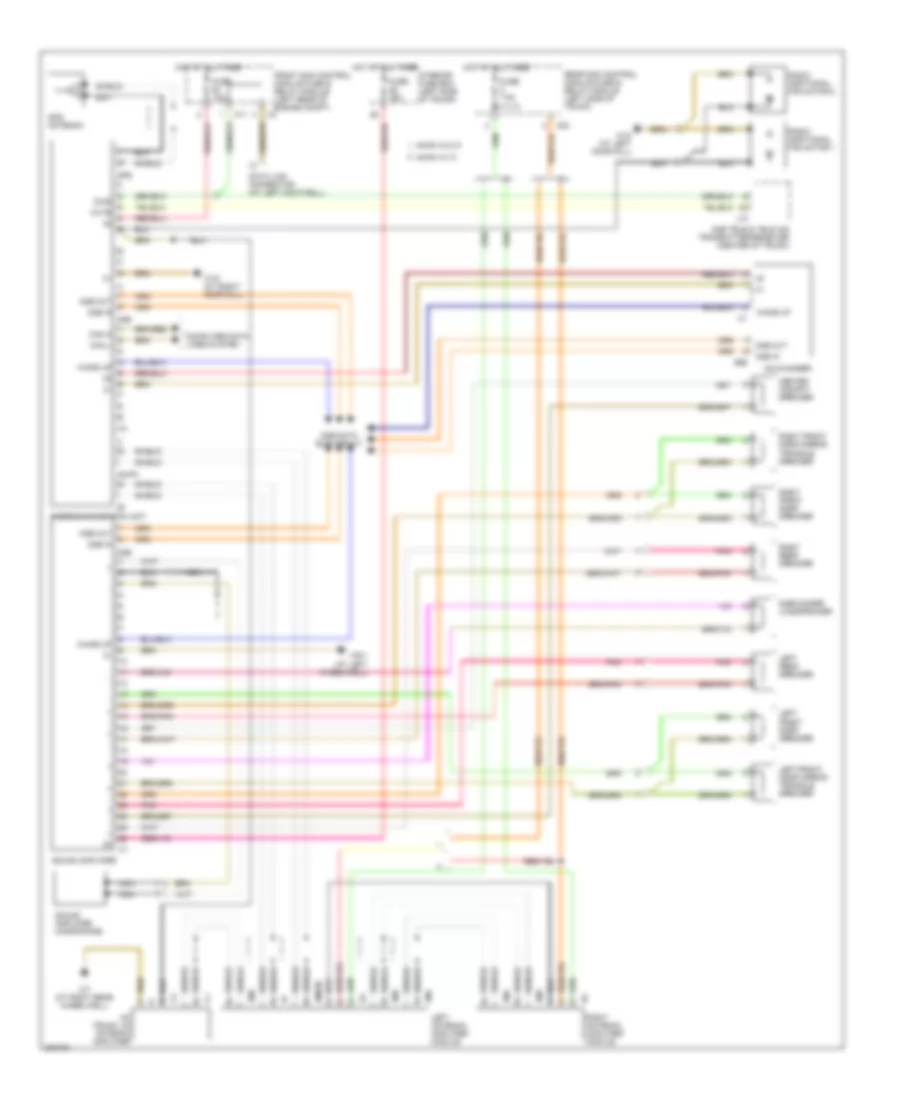
Power Windows Wiring Diagram, Except Convertible (2 of 2) for Mercedes-Benz CLK320 2005
List of elements for Power Windows Wiring Diagram, Except Convertible (2 of 2) for Mercedes-Benz CLK320 2005:
- 58d
- Fh h (+)
- Fh t (+)
- Fhs signal
- Fuse 30a
- H (+)
- H (-)
- H signal 1
- H signal 2
- Hot at all times
- Interior fuse box (left side of dash)
- Left rear power window motor
- Left rear power window switch
- Rear control module (left side of trunk)
- Right rear power window motor
- Right rear power window switch
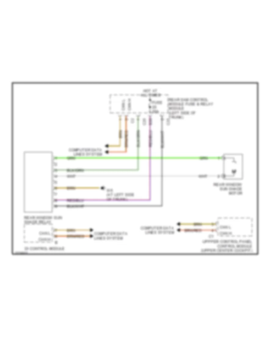
Rear Window Sun Shade Wiring Diagram for Mercedes-Benz CLK320 2005
List of elements for Rear Window Sun Shade Wiring Diagram for Mercedes-Benz CLK320 2005:
- C25
- Can h
- Can l
- Computer data lines system
- Di control module
- Fuse 20a
- Hot at all times
- Rear sam control module fuse & relay module (left side of trunk) c25
- Rear window sun shade motor
- Rear window sun shade relay
- S20
- Uppper control panel control module (upper center cockpit)
- W6 (at left side of trunk)
RADIO
Auto Pilot System Wiring Diagram, Convertible with Amplifier for Mercedes-Benz CLK320 2005
List of elements for Auto Pilot System Wiring Diagram, Convertible with Amplifier for Mercedes-Benz CLK320 2005:
- Am trunk lid antenna amplifier
- Am/fm
- Am/fm w/ if
- Am/fm w/o if
- C11
- C23
- Can h
- Can l
- Cd changer
- Center cockpit speaker
- Computer data lines system
- D2b
- D2b data bus circuit
- D2b in
- D2b out
- D2b tele & tele aid transmitter/receiver (center of trunk)
- Data link connector (at left footwell)
- Diag
- Fm3
- Fm4
- Front sam control module fuse & relay module (left rear of engine compt)
- Fuse 15a
- Fuse 25a
- Fuse 7.5a
- Gps
- Gps antenna
- Hot at all times
- Interior fuse box (left side of trunk)
- J10
- Left antenna amplifier module
- Left front door mirror triangle speaker
- Left front door speaker
- Left rear speaker
- Lmk
- Mute
- Nca
- Pnk
- Radio & navigation unit
- Radio additional fan motor 1
- Radio additional fan motor 2
- Rear sam control module fuse & relay module (left side of trunk)
- Right antenna amplifier module
- Right front door mirror triangle speaker
- Right front door speaker
- Right rear speaker
- Shield
- Sound amplifier
- Sound amplifier microphone
- Subwoofer loudspeaker
- W18 (at left door sill)
- W19 (at right door sill)
- W6/1 (at left wheelwell)
- W7 (at right rear wheelwell)
- Wake up
Auto Pilot System Wiring Diagram, Convertible without Amplifier for Mercedes-Benz CLK320 2005
List of elements for Auto Pilot System Wiring Diagram, Convertible without Amplifier for Mercedes-Benz CLK320 2005:
- A a
- Am trunk lid antenna amplifier
- Am/fm
- Am/fm w/ if
- Am/fm w/o if
- Bass module loudspeaker
- C11
- C23
- Can h
- Can l
- Cd changer
- Computer data lines system
- D2b
- D2b data bus circuit
- D2b in
- D2b out
- D2b tele & tele aid transmitter/ receiver (center of trunk)
- Data link connector (at left footwell)
- Diag
- Fm3
- Fm4
- Front sam control module fuse & relay module (left rear of engine compt)
- Fuse 15a
- Fuse 7.5a
- Gps
- Gps antenna
- Hot at all times
- J10
- Left antenna amplifier module
- Left front door mirror triangle speaker
- Left front door speaker
- Left rear speaker
- Lmk
- Mute
- Pnk
- Radio & navigation unit
- Radio additional fan motor 1
- Radio additional fan motor 2
- Rear sam control module fuse & relay module (left side of trunk)
- Right antenna amplifier module
- Right front door mirror triangle speaker
- Right front door speaker
- Right rear speaker
- Shield
- W18 (at left door sill)
- W19 (at right (at right door sill) door sill)
- W7 (at right rear wheelwell)
- Wake up
Auto Pilot System Wiring Diagram, Except Convertible with Amplifier for Mercedes-Benz CLK320 2005
List of elements for Auto Pilot System Wiring Diagram, Except Convertible with Amplifier for Mercedes-Benz CLK320 2005:
- Am/fm
- Amplifier module 1
- C11
- C23
- Can h
- Can l
- Cd changer
- Center cockpit speaker
- Computer data lines system
- Control
- D2b
- D2b data bus circuit
- D2b in
- D2b out
- D2b tele & tele aid transmitter/receiver (center of trunk)
- Data link connector (at left footwell)
- Diag
- Front sam control module fuse & relay module (left rear of engine compt)
- Fuse 15a
- Fuse 25a
- Fuse 7.5a
- Gps
- Gps antenna
- Hot at all times
- Interior fuse box (left side of trunk)
- J10
- Left front door mirror triangle speaker
- Left front door speaker
- Left rear speaker
- Mute
- N.c.
- Nca
- Pnk
- Radio & navigation unit
- Radio additional fan motor 1
- Radio additional fan motor 2
- Rear sam control module fuse & relay module (left side of trunk)
- Right front door mirror triangle speaker
- Right front door speaker
- Right rear speaker
- Shield
- Sound amplifier
- Sound amplifier microphone
- Subwoofer loudspeaker
- W18 (at left door sill)
- W19 (at right door sill)
- W29/3 (left front engine compt)
- W6 (at left side of trunk)
- W7 (at right rear wheelhouse)
- Wake up
Auto Pilot System Wiring Diagram, Except Convertible without Amplifier for Mercedes-Benz CLK320 2005
List of elements for Auto Pilot System Wiring Diagram, Except Convertible without Amplifier for Mercedes-Benz CLK320 2005:
- Am/fm
- Amplifier module 1
- Bass module loudspeaker
- C11
- C23
- Can h
- Can l
- Cd changer
- Computer data lines system
- D2b
- D2b data bus circuit
- D2b in
- D2b out
- D2b tele & tele aid transmitter/receiver (center of trunk)
- Data link connector (at left footwell)
- Diag
- Front sam control module fuse & relay module (left rear of engine compt)
- Fuse 15a
- Fuse 7.5a
- Gps
- Gps antenna
- Hot at all times
- J10
- Left front door mirror triangle speaker
- Left front door speaker
- Left rear speaker
- Mute
- Nca
- Pnk
- Radio & navigation unit
- Radio additional fan motor 1
- Radio additional fan motor 2
- Rear sam control module fuse & relay module (left side of trunk)
- Right front door mirror triangle speaker
- Right front door speaker
- Right rear speaker
- Shield
- W18 (at left door sill)
- W19 (at right door sill)
- W29/3 (left front engine compt)
- Wake up
COMAND Actuation Wiring Diagram, Convertible (1 of 2) for Mercedes-Benz CLK320 2005
List of elements for COMAND Actuation Wiring Diagram, Convertible (1 of 2) for Mercedes-Benz CLK320 2005:
- Am trunk lid antenna amplifier
- Am/fm
- Am/fm w/ if
- Am/fm w/o if
- C11
- C23
- Can h
- Can l
- Computer data lines system
- Connection
- Control
- D2b
- D2b in
- D2b out
- D2b tele & tele aid transmitter/receiver (center of trunk)
- Data link connector (at left footwell)
- Diag
- Fm3
- Fm4
- Front sam control module fuse & relay module (left rear of engine compt)
- Fuse 15a
- Fuse 7.5a
- Gps
- Gps antenna
- Hot at all times
- J10
- Left antenna amplifier module
- Lmk
- Mute
- N.c.
- Nca
- Nf-l
- Nf-r
- Radio & navigation unit
- Rear sam control module fuse & relay module (left side of trunk)
- Right antenna amplifier module
- Shield
- W19 (at right door sill)
- W7 (at right rear wheelwell)
- Wake up
- Walkman
COMAND Actuation Wiring Diagram, Convertible (2 of 2) for Mercedes-Benz CLK320 2005
List of elements for COMAND Actuation Wiring Diagram, Convertible (2 of 2) for Mercedes-Benz CLK320 2005:
- Cd changer
- Center cockpit speaker
- D2b
- D2b data bus circuit
- D2b in
- D2b out
- Fuse 25a
- Hot at all times
- Interior fuse box (left side of trunk)
- Left front door mirror triangle speaker
- Left front door speaker
- Left rear speaker
- Nca
- Pnk
- Right front door mirror triangle speaker
- Right front door speaker
- Right rear speaker
- Sound amplifier
- Sound amplifier microphone
- Subwoofer loudspeaker
- W6 (at left side of trunk)
- W7 (at right rear wheelhouse)
- Wake up
COMAND Actuation Wiring Diagram, Except Convertible (1 of 2) for Mercedes-Benz CLK320 2005
List of elements for COMAND Actuation Wiring Diagram, Except Convertible (1 of 2) for Mercedes-Benz CLK320 2005:
- Am/fm
- Amplifier module 1
- C11
- C23
- Can h
- Can l
- Computer data lines system
- Connection
- Control
- D2b
- D2b in
- D2b out
- D2b tele & tele aid transmitter/receiver (center of trunk)
- Data link connector (at left footwell)
- Diag
- Front sam control module fuse & relay module (left rear of engine compt)
- Fuse 15a
- Fuse 7.5a
- Gps
- Gps antenna
- Hot at all times
- J10
- Mute
- N.c.
- Nca
- Nf-l
- Nf-r
- Radio & navigation unit
- Rear sam control module fuse & relay module (left side of trunk)
- Red
- Shield
- Tv tuner
- Tv1
- Tv2
- Tv3
- Tv4
- W19 (at right door sill)
- W29/3 (left front engine compt)
- Wake up
- Walkman
COMAND Actuation Wiring Diagram, Except Convertible (2 of 2) for Mercedes-Benz CLK320 2005
List of elements for COMAND Actuation Wiring Diagram, Except Convertible (2 of 2) for Mercedes-Benz CLK320 2005:
- Cd changer
- Center cockpit speaker
- D2b
- D2b data bus circuit
- D2b in
- D2b out
- Fuse 25a
- Hot at all times
- Interior fuse box (left side of trunk)
- Left front door mirror triangle speaker
- Left front door speaker
- Left rear speaker
- Nca
- Pnk
- Right front door mirror triangle speaker
- Right front door speaker
- Right rear speaker
- Sound amplifier
- Sound amplifier microphone
- Subwoofer loudspeaker
- W6 (at left side of trunk)
- W7 (at right rear wheelhouse)
- Wake up
D2B Data Bus Wiring Diagram for Mercedes-Benz CLK320 2005
List of elements for D2B Data Bus Wiring Diagram for Mercedes-Benz CLK320 2005:
- Cd changer
- Command operating, display & control unit
- Computer data lines system
- D2b
- D2b fiber optics connector (front center of console)
- D2b in
- D2b out
- D2b telephone & tele aid transmitter/receiver
- Diag
- J10
- Radio
- Radio & navigation unit
- Sdars control unit
- Sound amplifier
- Telephone interface
- Voice control system control module
- W/ auto pilot circuit
- W/ command actuation circuit
- W/ radio circuit
- Wake up
- Wake up signal connector (inside interior of right footwell)
Radio Wiring Diagram, Convertible with Amplifier, with D2B Data Bus for Mercedes-Benz CLK320 2005
List of elements for Radio Wiring Diagram, Convertible with Amplifier, with D2B Data Bus for Mercedes-Benz CLK320 2005:
- Am trunk lid antenna amplifier
- Am/fm
- Am/fm w/ if
- Am/fm w/o if
- C11
- C23
- Can h
- Can l
- Cd changer
- Center cockpit speaker
- Computer data lines system
- Control
- D2b
- D2b data bus circuit
- D2b in
- D2b out
- D2b tele & tele aid transmitter/receiver (center of trunk)
- Data link connector (at left footwell)
- Diag
- Fm3
- Fm4
- Front sam control module fuse & relay module (left rear of engine compt)
- Fuse 15a
- Fuse 25a
- Fuse 7.5a
- Hot at all times
- Interior fuse box (left side of trunk)
- J10
- Left antenna amplifier module
- Left front door mirror triangle speaker
- Left front door speaker
- Left rear speaker
- Lmk
- Mute
- Nca
- Pnk
- Radio
- Rear sam control module fuse & relay module (left side of trunk)
- Right antenna amplifier module
- Right front door mirror triangle speaker
- Right front door speaker
- Right rear speaker
- Shield
- Sound amplifier
- Sound amplifier microphone
- Subwoofer loudspeaker
- W19 (at right door sill)
- W6/1 (at left wheelwell)
- W7 (at right rear wheelwell)
- Wake up
Radio Wiring Diagram, Convertible with Amplifier, without D2B Data Bus for Mercedes-Benz CLK320 2005
List of elements for Radio Wiring Diagram, Convertible with Amplifier, without D2B Data Bus for Mercedes-Benz CLK320 2005:
- (at left wheelwell) w6/1
- Am trunk lid antenna amplifier
- Am/fm
- Am/fm w/ if
- Am/fm w/o if
- C11
- C23
- Can h
- Can l
- Cd changer
- Center cockpit speaker
- Computer data lines system
- Control
- D2b tele & tele aid transmitter/ receiver (center of trunk)
- Data link connector (at left footwell)
- Diag
- Fm3
- Fm4
- Front sam control module fuse & relay module (left rear of engine compt)
- Fuse 15a
- Fuse 25a
- Fuse 7.5a
- Hot at all times
- Interior fuse box (left side of trunk)
- J10
- Left antenna amplifier module
- Left front door mirror triangle speaker
- Left front door speaker
- Left rear speaker
- Lmk
- Mute
- Nca
- Pnk
- Radio
- Rear sam control module fuse & relay module (left side of trunk)
- Right antenna amplifier module
- Right front door mirror triangle speaker
- Right front door speaker
- Right rear speaker
- Shield
- Sound amplifier
- Sound amplifier microphone
- Subwoofer loudspeaker
- W19 (at right door sill)
- W7 (at right rear wheelwell)
Radio Wiring Diagram, Convertible without Amplifier, with D2B Data Bus for Mercedes-Benz CLK320 2005
List of elements for Radio Wiring Diagram, Convertible without Amplifier, with D2B Data Bus for Mercedes-Benz CLK320 2005:
- A a
- Am trunk lid antenna amplifier
- Am/fm
- Am/fm w/ if
- Am/fm w/o if
- C11
- C23
- Can h
- Can l
- Cd changer
- Computer data lines system
- Control
- D2b
- D2b data bus circuit
- D2b in
- D2b out
- D2b tele & tele aid transmitter/ receiver (center of trunk)
- Data link connector (at left footwell)
- Diag
- Fm3
- Fm4
- Front sam control module fuse & relay module (left rear of engine compt)
- Fuse 15a
- Fuse 7.5a
- Hot at all times
- J10
- Left antenna amplifier module
- Left front door mirror triangle speaker
- Left front door speaker
- Left rear speaker
- Lmk
- Mute
- Pnk
- Radio
- Rear sam control module fuse & relay module (left side of trunk)
- Right antenna amplifier module
- Right front door mirror triangle speaker
- Right front door speaker
- Right rear speaker
- Shield
- W19 (at right (at right door sill) door sill)
- W7 (at right rear wheelwell)
- Wake up
Radio Wiring Diagram, Convertible without Amplifier, without D2B Data Bus for Mercedes-Benz CLK320 2005
List of elements for Radio Wiring Diagram, Convertible without Amplifier, without D2B Data Bus for Mercedes-Benz CLK320 2005:
- Am trunk lid antenna amplifier
- Am/fm
- Am/fm w/ if
- Am/fm w/o if
- C11
- C23
- Can h
- Can l
- Cd changer
- Computer data lines system
- Control
- D2b tele & tele aid transmitter/ receiver (center of trunk)
- Data link connector (at left footwell)
- Diag
- Fm3
- Fm4
- Front sam control module fuse & relay module (left rear of engine compt)
- Fuse 15a
- Fuse 7.5a
- Hot at all times
- J10
- Left antenna amplifier module
- Left front door mirror triangle speaker
- Left front door speaker
- Left rear speaker
- Lmk
- Mute
- Pnk
- Radio
- Rear sam control module fuse & relay module (left side of trunk)
- Right antenna amplifier module
- Right front door mirror triangle speaker
- Right front door speaker
- Right rear speaker
- Shield
- W19 (at right door sill)
- W7 (at right rear wheelwell)
Radio Wiring Diagram, Except Convertible with Amplifier, with D2B Data Bus for Mercedes-Benz CLK320 2005
List of elements for Radio Wiring Diagram, Except Convertible with Amplifier, with D2B Data Bus for Mercedes-Benz CLK320 2005:
- Am/fm
- Amplifier module 1
- C11
- C23
- Can h
- Can l
- Cd changer
- Center cockpit speaker
- Computer data lines system
- Control
- D2b
- D2b data bus circuit
- D2b in
- D2b out
- D2b tele & tele aid transmitter/receiver (center of trunk)
- Data link connector (at left footwell)
- Diag
- Front sam control module fuse & relay module (left rear of engine compt)
- Fuse 15a
- Fuse 25a
- Fuse 7.5a
- Hot at all times
- Interior fuse box (left side of trunk)
- J10
- Left front door mirror triangle speaker
- Left front door speaker
- Left rear speaker
- Mute
- Nca
- Pnk
- Radio
- Rear sam control module fuse & relay module (left side of trunk)
- Right front door mirror triangle speaker
- Right front door speaker
- Right rear speaker
- Shield
- Sound amplifier
- Sound amplifier microphone
- Subwoofer loudspeaker
- W19 (at right door sill)
- W29/3 (left front engine compt)
- W6 (at left side of trunk)
- W7 (at right rear wheelhouse)
- Wake up
Radio Wiring Diagram, Except Convertible with Amplifier, without D2B Data Bus (1 of 2) for Mercedes-Benz CLK320 2005
List of elements for Radio Wiring Diagram, Except Convertible with Amplifier, without D2B Data Bus (1 of 2) for Mercedes-Benz CLK320 2005:
- Am/fm
- Amplifier module 1
- Bass module loudspeaker
- C11
- C23
- Can h
- Can l
- Cd changer
- Computer data lines system
- Control
- D2b
- D2b data bus circuit
- D2b in
- D2b out
- D2b tele & tele aid transmitter/ receiver (center of trunk)
- Data link connector (at left footwell)
- Diag
- Front sam control module fuse & relay module (left rear of engine compt)
- Fuse 15a
- Fuse 7.5a
- Hot at all times
- J10
- Left front door mirror triangle speaker
- Left front door speaker
- Left rear speaker
- Mute
- Nca
- Pnk
- Radio
- Rear sam control module fuse & relay module (left side of trunk)
- Right front door mirror triangle speaker
- Right front door speaker
- Right rear speaker
- Shield
- W19 (at right door sill)
- W29/3 (left front engine compt)
- Wake up
Radio Wiring Diagram, Except Convertible with Amplifier, without D2B Data Bus (2 of 2) for Mercedes-Benz CLK320 2005
List of elements for Radio Wiring Diagram, Except Convertible with Amplifier, without D2B Data Bus (2 of 2) for Mercedes-Benz CLK320 2005:
- (at right door sill) w19
- Am/fm
- Amplifier module 1
- C11
- C23
- Can h
- Can l
- Cd changer
- Center cockpit speaker
- Computer data lines system
- Control
- D2b tele & tele aid transmitter/ receiver (center of trunk)
- Data link connector (at left footwell)
- Diag
- Front sam control module fuse & relay module (left rear of engine compt)
- Fuse 15a
- Fuse 25a
- Fuse 7.5a
- Hot at all times
- Interior fuse box (left side of trunk)
- J10
- Left front door mirror triangle speaker
- Left front door speaker
- Left rear speaker
- Mute
- Nca
- Pnk
- Radio
- Rear sam control module fuse & relay module (left side of trunk)
- Right front door mirror triangle speaker
- Right front door speaker
- Right rear speaker
- Shield
- Sound amplifier
- Sound amplifier microphone
- Subwoofer loudspeaker
- W29/3 (left front engine compt)
- W6 (at left side of trunk)
- W7 (at right rear wheelhouse)
Radio Wiring Diagram, Except Convertible without Amplifier, without D2B Data Bus for Mercedes-Benz CLK320 2005
List of elements for Radio Wiring Diagram, Except Convertible without Amplifier, without D2B Data Bus for Mercedes-Benz CLK320 2005:
- Am/fm
- Amplifier module 1
- Bass module loudspeaker
- C11
- C23
- Can h
- Can l
- Cd changer
- Computer data lines system
- Control
- D2b tele & tele aid transmitter/ receiver (center of trunk)
- Data link connector (at left footwell)
- Diag
- Front sam control module fuse & relay module (left rear of engine compt)
- Fuse 15a
- Fuse 7.5a
- Hot at all times
- J10
- Left front door mirror triangle speaker
- Left front door speaker
- Left rear speaker
- Mute
- Nca
- Pnk
- Radio
- Rear sam control module fuse & relay module (left side of trunk)
- Right front door mirror triangle speaker
- Right front door speaker
- Right rear speaker
- Shield
- W19 (at right door sill)
- W29/3 (left front engine compt)
Satellite Radio Wiring Diagram for Mercedes-Benz CLK320 2005
List of elements for Satellite Radio Wiring Diagram for Mercedes-Benz CLK320 2005:
- (at right rear wheelhouse) w7
- D2b
- D2b data bus circuit
- D2b in
- D2b out
- Fuse 20a
- Hot at all times
- Rear sam control module fuse & relay module (left side of trunk)
- Sat
- Sdars control unit (right rear of trunk)
- Shield
- Ter
- Vics antenna
Voice Activation Wiring Diagram for Mercedes-Benz CLK320 2005
List of elements for Voice Activation Wiring Diagram for Mercedes-Benz CLK320 2005:
- D2b
- D2b data bus circuit
- D2b telephone & tele aid transmitter/ receiver
- Fuse 20a
- Fuse 5a
- Hands free microphone
- Hot at all times
- Hot in acc, run or start
- J10
- Nca
- Rear sam control module fuse & relay module (left side of trunk)
- Telephone system
- Voice control system control module
- W7 (at right rear wheelwell)
SHIFT INTERLOCK
Shift Interlock Wiring Diagram for Mercedes-Benz CLK320 2005
List of elements for Shift Interlock Wiring Diagram for Mercedes-Benz CLK320 2005:
- 2003 & 2004
- C10
- C22
- Can (+)
- Can (-)
- Can h
- Can l
- Computer data lines system
- Data link connector (at left footwell)
- Di control module (left side of dash)
- Diag
- Electric steering lock control module (upper left footwell)
- Electronic selector lever control module (base of gear selector lever)
- Esp/bas control module (left side of eng compt)
- Etc control module (behind right kick panel)
- Front sam control module fuse & relay module (left rear of engine compt)
- Gear display sensor (in center console)
- Ground
- Instrument cluster
- Keyless go/start push button (center console)
- Me-sfi (me) control module (left side of engine)
- N.c.
- Nca
- Pnk
- Red
- Steering column lock ind switch
- Steering column module
- W19 (at right doorsill)
- W19 (at right doorsill) w18 (at left doorsill)
STARTING/CHARGING
Charging Wiring Diagram for Mercedes-Benz CLK320 2005
List of elements for Charging Wiring Diagram for Mercedes-Benz CLK320 2005:
- Battery
- C18
- Front sam control module fuse & relay module (left rear of engine comtp)
- Generator
- Me-sfi (me) control module (left side of engine)
- Starter
- W10 (at right rear of engine compt)
Starting Wiring Diagram for Mercedes-Benz CLK320 2005
List of elements for Starting Wiring Diagram for Mercedes-Benz CLK320 2005:
- Battery
- C17
- C19
- Circuit 87 relay, engine
- Di control module
- Engine controls system
- Front prefuse box (right rear of engine compt)
- Front sam control module fuse & relay module (left rear of engine compt)
- Fuse 15a
- Fuse 60a
- Generator
- Hot at all times
- Me-sfi (me) control module (left side of engine)
- Pnk/red
- Red
- Starter
- Starter relay
- W10 (at right rear of engine compt)
- W16/3 (at left front of engine compt)
SUPPLEMENTAL RESTRAINTS
Supplemental Restraints Wiring Diagram (1 of 2) for Mercedes-Benz CLK320 2005
List of elements for Supplemental Restraints Wiring Diagram (1 of 2) for Mercedes-Benz CLK320 2005:
- (pins 5 thru 32: not used)
- 15r
- Ab bf1+
- Ab bf1-
- Ab bf2+
- Ab bf2-
- Ab f1+
- Ab f1-
- Ab f2+
- Ab f2-
- Belt
- Belt tension sensor (right front door sill)
- C12
- Can h
- Can l
- Computer data lines system
- Crash sig
- Driver seat belt buckle restraint systems switch
- Drvr belt
- Front sam control module w/ fuse & relay module (left rear of engine compt)
- Gs bf+
- Gs bf-
- Gs f+
- Gs f-
- Gs hl+
- Gs hl-
- Gs hr+
- Gs hr-
- Left airbags sensor (under left rear seat)
- Left frontal accel- eration sensor
- Left rear etr squib (under left rear seat)
- Pass belt
- Passenger seat belt buckle restraint systems switch
- Pnk
- Press
- Pressure sensor (under right front seat)
- Red
- Restraint systems control module (under center console, left of shifter)
- Right airbags sensor (under right rear seat)
- Right frontal accel- eration sensor
- Right rear etr squib (under right rear seat)
- Sb hl+
- Sb hl-
- Sb hr+
- Sb hr-
- Sb vl+
- Sb vl-
- Sb vr+
- Sb vr-
- Side l
- Side r
- Upfront l
- Upfront r
- W26 (under center console, left of shifter)
- Wb l+
- Wb l-
- Wb r+
- Wb r-
- Weight sensing system (wss) control unit (under right front seat)
Supplemental Restraints Wiring Diagram (2 of 2) for Mercedes-Benz CLK320 2005
List of elements for Supplemental Restraints Wiring Diagram (2 of 2) for Mercedes-Benz CLK320 2005:
- Clockspring
- Driver airbag squib 1 (behind drivers airbag)
- Driver airbag squib 2 (behind drivers airbag)
- Driver etr squib (at base of left "b" pillar)
- Front passenger airbag squib 1 (behind right side of dash)
- Front passenger airbag squib 2 (behind right side of dash)
- Front passenger etr squib (at base of right "b" pillar)
- Left front side airbag squib (in left front door)
- Left rear side airbag squib (in left rear door)
- Left rear window airbag squib (coupe) (at left "c" pillar)
- Pnk
- Right front side airbag squib (in left front door)
- Right front side airbag squib (in right front door)
- Right rear side airbag squib (in right rear door)
- Right rear window airbag squib (coupe) (at right "c" pillar)
- Steering column module
- W/ cabriolet
- W/o cabriolet
- W18 (left front seat crossmember)
- W19 (right front seat crossmember)
TRANSMISSION
A/T Wiring Diagram for Mercedes-Benz CLK320 2005
List of elements for A/T Wiring Diagram for Mercedes-Benz CLK320 2005:
- 1-2/ 4-5 valve
- 2-3 shift valve
- 2003 & 2004
- 3-4 shift valve
- C10
- C22
- Can (+)
- Can (-)
- Can h
- Can l
- Computer data lines system
- Data link connector (at left footwell)
- Di control module (left side of dash)
- Diag
- Electric steering lock control module (upper left footwell)
- Electronic selector lever control module (base of gear selector lever)
- Etc control module (behind right kick panel)
- Front sam control module fuse & relay module (left rear of engine compt)
- Gear display sensor (in center console)
- Ground
- Keyless go/start push buttom (center console)
- Lock up valve
- Modul- ator valve
- N.c.
- Nca
- Pnk
- Red
- Rpm sensor
- Shift valve
- Signal
- Start interlock switch
- Steering column lock ind switch
- Steering column module
- Temp sensor
- Valve unit (in automatic transmission)
- W19 (at right doorsill)
- W19 (at right doorsill) w18 (at left doorsill)
TRUNK, TAILGATE, FUEL DOOR
Trunk Release Wiring Diagram for Mercedes-Benz CLK320 2005
List of elements for Trunk Release Wiring Diagram for Mercedes-Benz CLK320 2005:
- (at left door sill) w18
- (at right door sill) w19
- (not used)
- 2004 & 2005
- C21
- C24
- Can h
- Can l
- Computer data lines system
- Coupe convertible
- Left door contact switch
- Pawl rotary tumbler switch
- Power tops system
- Rear sam control module fuse & relay module (left side of trunk)
- Remote trunk lid release switch
- Rhr release valve (coupe)
- Right door contact switch
- Trunk lid contact switch
- Trunk lid external operation switch
- Trunk light
- W6 (at left side of trunk) w6/1 (left wheelwell)
WARNING SYSTEMS
Tire Pressure Monitoring Wiring Diagram for Mercedes-Benz CLK320 2005
List of elements for Tire Pressure Monitoring Wiring Diagram for Mercedes-Benz CLK320 2005:
- C17
- Can h
- Can l
- Computer data lines system
- Data
- Fuse 20a
- Grd
- Hot at all times
- Left front tpm wheel antenna
- Left front tpm wheel sensor
- Left rear tpm wheel antenna
- Left rear tpm wheel sensor
- Nca
- Rear sam control module fuse & relay module (left side of trunk)
- Right front tpm wheel antenna
- Right front tpm wheel sensor
- Right rear tpm wheel antenna
- Right rear tpm wheel sensor
- Tps control module
WIPER/WASHER
Front Wiper/Washer Wiring Diagram for Mercedes-Benz CLK320 2005
List of elements for Front Wiper/Washer Wiring Diagram for Mercedes-Benz CLK320 2005:
- 15a
- C16
- C20
- Can h
- Can l
- Combination switch
- Computer data lines system
- Cooling fans system
- Front sam control module fuse & relay module (left rear of engine compt)
- Fuse 40a
- Fuse 43b 15a
- Hot w/ fan relay module energized
- Nca
- Overhead control panel control module
- Rain/light sensor (top center of windshield)
- Red
- Steering column control module
- W16/3 (at left front of engine compt)
- W9 (left front of engine compt)
- Washer nozzle heater
- Washer nozzle hose heater
- Windshield washer fluid level indicator switch
- Windshield washer fluid pump
- Windshield wiper sw
- Wiper motor
- Wiper relay on/off
- Wiper relay stage 1 & 2
- Wiper switch
Headlamp Washer Wiring Diagram for Mercedes-Benz CLK320 2005
List of elements for Headlamp Washer Wiring Diagram for Mercedes-Benz CLK320 2005:
- C15
- C19
- C20
- Can h
- Can l
- Computer data lines system
- Di control
- Front sam control module fuse & relay module (left rear of engine compt)
- Fuse 5a
- Hcs pump (front left footwell)
- Hot at all times
- Light switch module (left side of dash)
- Sra
- W28/2 (at right doorsill)

 Čeština
 Dansk
Dansk Deutsch
 English
 English
 Español
 Suomi
Suomi Français
 Français
 עברית
עברית Hrvatski
 Magyar
 Italiano
 日本語
日本語 한국어
한국어 Nederlands
 Polski
 Português
 Português
 Română
 Русский
 Slovenčina
 Slovenščina
 Svenska
 Türkçe
 中文 (中国)