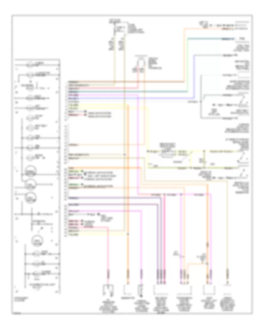
AIR CONDITIONING
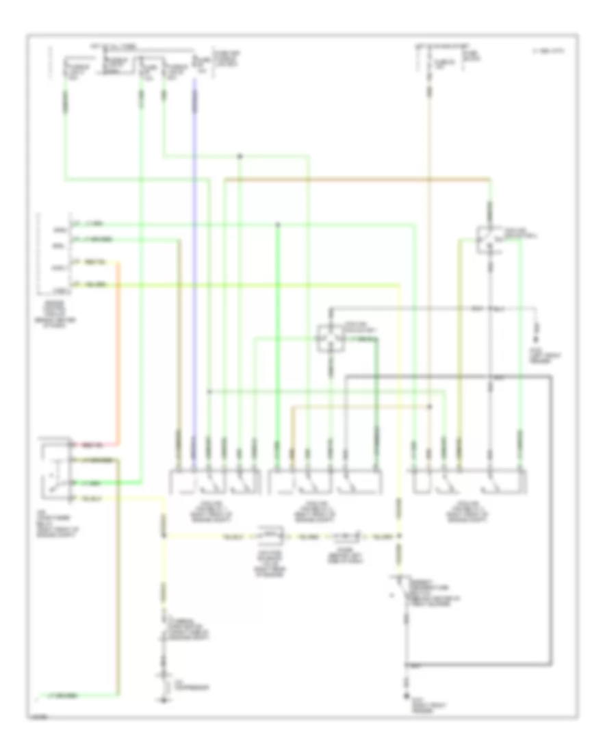
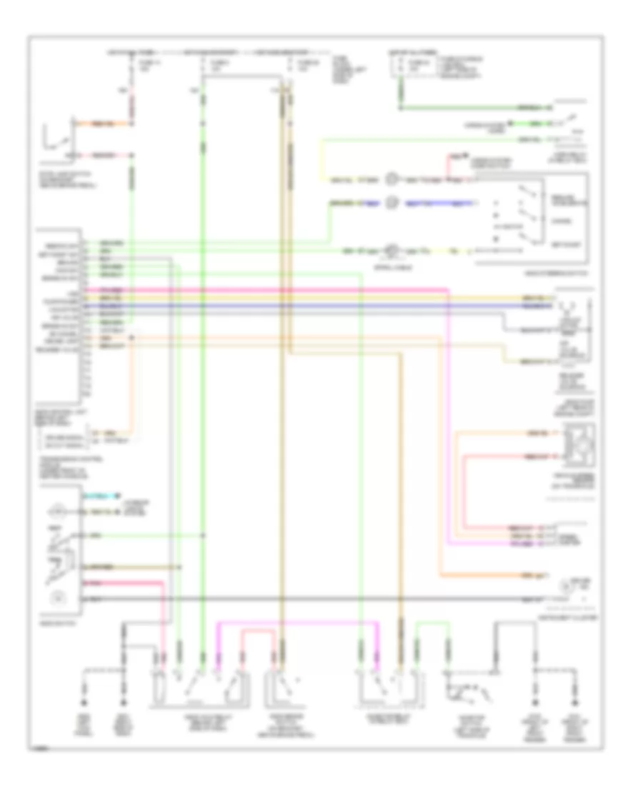
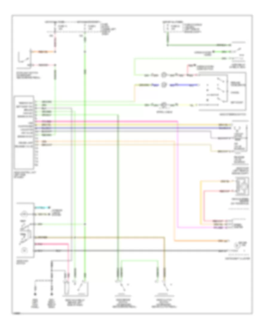
A/C Wiring Diagram (1 of 2) for Nissan Altima GLE 1998
 https://portal-diagnostov.com/license.html
Automotive Electricians Portal FZCO
Automotive Electricians Portal FZCO
https://portal-diagnostov.com/license.html
https://portal-diagnostov.com/license.html
Automotive Electricians Portal FZCO
Automotive Electricians Portal FZCO
List of elements for A/C Wiring Diagram (1 of 2) for Nissan Altima GLE 1998:
- (+) face, (-) def
- (+) fre, (-) rec
- (-) fre, (+) rec
- (-) vent, (+) def
- (right side of dash)
- 10s
- 1994 vftc c
- 3m 3m
- A/c switch
- B/l
- B/l input
- Blower motor
- Cool position
- Def
- Def input
- Engine control module (behind center
- F/cool, m/sw
- F/d
- F/d input
- Face
- Face input
- Fan hi
- Fan switch
- Foot
- Foot input
- Fre
- Fre input
- Full cool switch (center of dash)
- Fuse 1 fuse 1 15a 15a
- Fuse 2 15a
- Fuse 6 10a
- Fuse 8 10a
- Fuse block
- G101 (right front fender)
- G203 (right side kick panel)
- Ground
- Hot in on
- Hot in on, or start
- Ign
- Ill
- Instrument cluster system
- Intake door motor (right side of dash)
- Interior lights system
- Mode door motor (center of dash)
- Of dash)
- Off
- Others
- Pnk
- Psdw
- Push control unit
- Rec
- Rec input
- Red
- Resistor
- Thermal transmitter (right side of engine compt)
- Thermo amp
- Thermo control amplifier (right side of dash)
- Triple pressure switch (left front of engine compt)
- Water temp
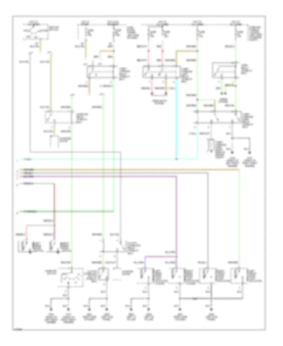
A/C Wiring Diagram (2 of 2) for Nissan Altima GLE 1998
List of elements for A/C Wiring Diagram (2 of 2) for Nissan Altima GLE 1998:
- 1994 vftc c
- A/c compressor
- Acrly
- Air conditioner relay (right front of engine compt)
- Ambient temperature switch (behind center of front bumper)
- Cooling fan motor 1
- Cooling fan motor 2
- Cooling fan relay 1 (right front of engine compt)
- Cooling fan relay 2 (right front of engine compt)
- Cooling fan relay 3 (right front of engine compt)
- Diode (behind left side of dash)
- Engine control module (behind center of dash)
- Fuse 10a
- Fuse 25 10a
- Fuse and fusible link box
- Fuse block
- Fusible link b 40a
- Fusible link c 40a
- Fusible link e 100a
- G100 (left front fender)
- G101 (right front fender)
- Hot at all times
- Hot in on and start
- Iacv-ficd solenoid valve (right rear of engine)
- Nca
- Rfrh
- Rfrl
- Tasw
- Thermal protector (right side of engine compt)
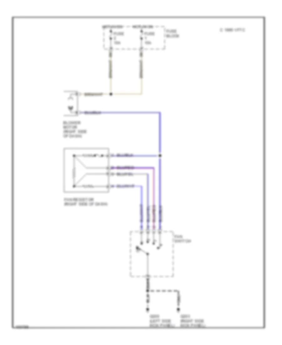
Heater Wiring Diagram for Nissan Altima GLE 1998
List of elements for Heater Wiring Diagram for Nissan Altima GLE 1998:
- 1995 vftc c
- Blower motor (right side of dash)
- Fan resistor (right side of dash)
- Fan switch
- Fuse 15a
- Fuse block
- G200 (left side kick panel)
- G203 (right side kick panel)
- Hot in on
- Off
ANTI-LOCK BRAKES
Anti-lock Brake Wiring Diagrams for Nissan Altima GLE 1998
List of elements for Anti-lock Brake Wiring Diagrams for Nissan Altima GLE 1998:
- (behind left side of dash) (consult) data link connector
- 16n
- 87a
- Abs actuator (left rear of engine compt)
- Abs control unit (behind left kick panel)
- Abs motor
- Abs relay unit (left side of engine compt)
- Abs warning lamp
- Bls
- Combination meter
- Diag l
- Exterior lights system
- Fl gnd
- Fl in
- Fl out
- Fl ss
- Fr gnd
- Fr in
- Fr out
- Fr ss
- Fuse & fusible link box (left side of engine compt)
- Fuse 10a
- Fuse 15a
- Fuse block (under left side of dash)
- Fuse f 40a
- Fuse h 40a
- G100 (front of left front fender)
- G200 (left kick panel)
- Gnd
- Gnd1
- Gnd2
- Hot at all times
- Hot in on or start
- Left front wheel speed sensor
- Left rear wheel speed sensor
- Motor relay
- Nca
- Pnk
- Red
- Right front wheel speed sensor
- Right rear wheel speed sensor
- Rl gnd
- Rl in
- Rl out
- Rl ss
- Rr gnd
- Rr in
- Rr out
- Rr ss
- Rxd
- Sila
- Solenoid valve relay
- Stop lamp switch
- Txd
ANTI-THEFT
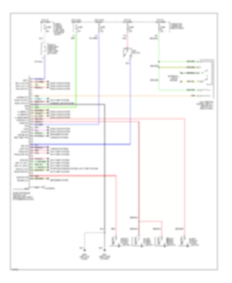
Anti-theft Wiring Diagram (1 of 2) for Nissan Altima GLE 1998
List of elements for Anti-theft Wiring Diagram (1 of 2) for Nissan Altima GLE 1998:
- 11k
- 11s
- Acc
- Batt
- Circuit breaker 1 (behind left side of dash)
- Closed
- Full
- Full stroke lock
- Full stroke unlock
- Fuse 10a
- Fuse and fusible link box (left side of engine compt)
- Fuse block (under left side of dash)
- Fuse d 40a
- G100 (front of left front fender)
- G101 (front of right front fender)
- G200 (left kick panel)
- G201 (right side of dash)
- G407 (center rear of trunk)
- Ground
- Hood sw
- Hood switch
- Hot at all times
- Hot in on or acc
- Hot in on or start
- Ign
- Indic output
- Key cyl sw(lock)
- Key cyl sw(unlk)
- Key sw
- Key switch
- L door sw
- Left door key cylinder switch
- Left front door switch
- Left unlk sensor
- Mid stroke
- Open
- Panic output
- Pnk
- R door sw
- Rear door sw
- Red
- Right door key cylinder switch
- Right front door switch
- Right unlk sensor
- Security indicator lamp
- Smart entrance control unit (behind dash, right side of steering column)
- Starter cut
- Stroke
- Trunk key cyl sw
- Trunk lid key cylinder switch
- Trunk room lamp switch
- Trunk sw
- Unlk sensor(rear)
Anti-theft Wiring Diagram (2 of 2) for Nissan Altima GLE 1998
List of elements for Anti-theft Wiring Diagram (2 of 2) for Nissan Altima GLE 1998:
- A/t
- Acc
- Closed
- Clutch interlock relay (in relay box)
- Clutch interlock switch (in relay box)
- Fuse 10a
- Fuse 15a
- Fuse and fusible link box (left side of engine compt)
- Fuse block (under left side of dash)
- G100 (front of left front fender)
- G101 (front of right front fender)
- G200 (left kick panel)
- G201 (right side of dash)
- G308 (left "b" pillar)
- G904 (left "c" pillar)
- Headlights system
- Horn relay (in relay box)
- Horns system
- Hot at all times
- Hot in on or start
- Hot in start
- Ignition switch
- Inhibitor relay (in relay box)
- Inhibitor switch
- Left front door lock actuator
- Left rear door lock actuator (4 door)
- Left rear door switch
- Locked
- M/t
- Off
- Open
- Red
- Right front door lock actuator
- Right rear door lock actuator (4 door)
- Right rear door switch
- Start
- Starter motor
- Theft warning horn (right rear of engine compt)
- Theft warning horn relay (in relay box)
- Theft warning lamp relay (in relay box)
- Theft warning relay (in relay box)
- Unlocked
BODY COMPUTER
Body Computer Wiring Diagrams for Nissan Altima GLE 1998
List of elements for Body Computer Wiring Diagrams for Nissan Altima GLE 1998:
- 11s
- 13n
- Acc
- Ant
- Antenna
- Anti-theft system
- Batt
- Circuit breaker 1 (behind left side of dash)
- Closed
- Defogger system
- Door locks system
- Door sw
- Door sw lh
- Door sw rh
- Dr lock out
- Dr ul out lh
- Dr ul out rh
- Exterior lights system
- Fuse & fusible link box (left side of engine compt)
- Fuse 10a
- Fuse block (under left side of dash)
- Fuse f 25a
- G200 (left kick panel)
- G201 (right side of dash)
- Gnd
- Hazard out
- Hood sw
- Hot at all times
- Hot in on or acc
- Hot in on or start
- Ign
- Indicator out
- Interior lights system
- Key cyl sw l
- Key cyl swul
- Key sw
- Key switch
- Left front door switch
- Left rear door switch
- Light sw
- Lock
- Multi-remote control relay 1 (behind left side of dash)
- Nca
- Open
- Panic output
- Pnk
- Red
- Right front door switch
- Right rear door switch
- Room lmp out
- Rr def out
- Rr def sw
- Seat belt sw
- Smart entrance control unit (behind dash, right of steering column)
- Starting/charging system, anti-theft system
- Str cut out
- Trunk key sw
- Trunk sw
- Ul sens lh
- Ul sens rear
- Ul sens rh
- Unlock
- Warning systems
COMPUTER DATA LINES
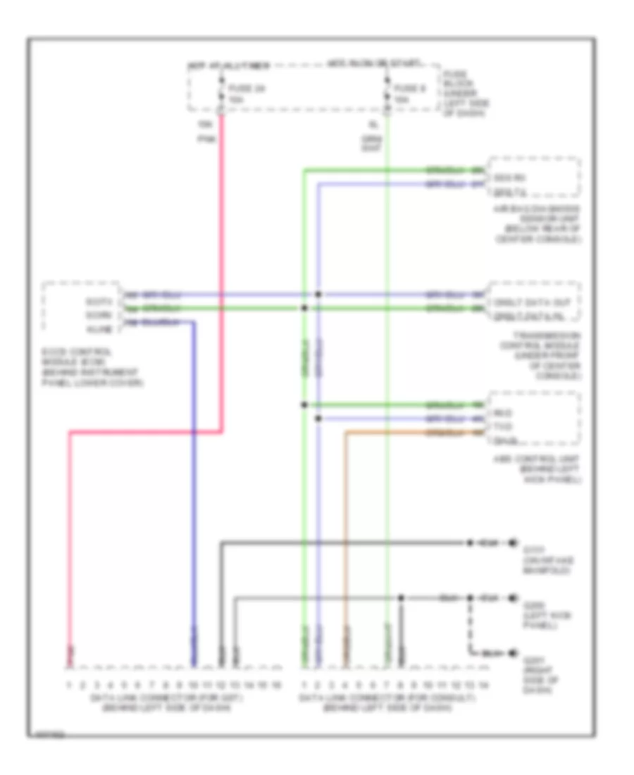
Computer Data Lines for Nissan Altima GLE 1998
List of elements for Computer Data Lines for Nissan Altima GLE 1998:
- 15k
- Abs control unit (behind left kick panel)
- Air bag diagnosis sensor unit (below rear of center console)
- Cnslt data in
- Cnslt data out
- Data link connector (for consult) (behind left side of dash)
- Data link connector (for gst) (behind left side of dash)
- Diagl
- Eccs control module (ecm) (behind instrument panel lower cover)
- Fuse 24 10a
- Fuse 8 10a
- Fuse block (under left side of dash)
- G131 (on intake manifold)
- G200 (left kick panel)
- G201 (right side of dash)
- Hot at all times
- Hot in on or start
- Kline
- Pnk
- Rxd
- Scirx
- Scitx
- Sss rx
- Sss tx
- Transmission control module (under front of center console)
- Txd
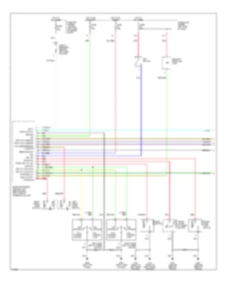
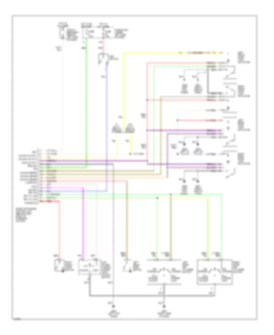
COOLING FAN
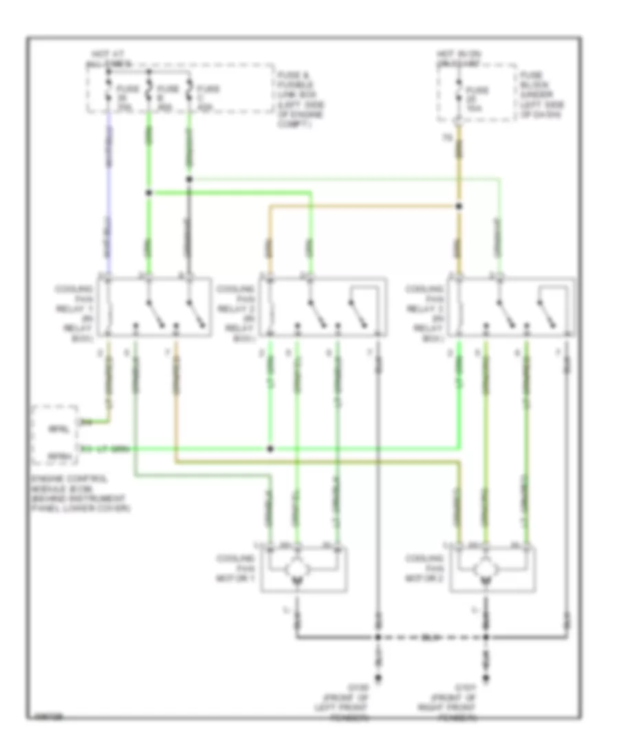
Cooling Fan Wiring Diagram for Nissan Altima GLE 1998
List of elements for Cooling Fan Wiring Diagram for Nissan Altima GLE 1998:
- Cooling fan motor 1
- Cooling fan motor 2
- Cooling fan relay 1 (in relay box)
- Cooling fan relay 2 (in relay box)
- Cooling fan relay 3 (in relay box)
- Engine control module (ecm) (behind instrument panel lower cover)
- Fuse & fusible link box (left side of engine compt)
- Fuse 10a
- Fuse b 40a
- Fuse block (under left side of dash)
- Fuse c 40a
- G100 (front of left front fender)
- G101 (front of right front fender)
- Hot at all times
- Hot in on or start
- Rfrh
- Rfrl
CRUISE CONTROL
Cruise Control Wiring Diagram, A/T for Nissan Altima GLE 1998
List of elements for Cruise Control Wiring Diagram, A/T for Nissan Altima GLE 1998:
- 11n
- 12n
- 16n
- Above brake pedal)
- Air valve
- Air valve solenoid
- Ascd brake switch (on bracket,
- Ascd control unit (behind left side of dash)
- Ascd hold relay (behind left side of dash)
- Ascd pump (left rear of engine compt)
- Ascd steering switch
- Ascd switch
- Brake nc sw
- Brake no sw
- Cancel
- Cruise
- Cruise lamp
- Cruise signal
- Fuse & fusible link box (left side of engine compt)
- Fuse 14 15a
- Fuse 25 10a
- Fuse 40 10a
- Fuse 8 10a
- Fuse block (under left side of dash)
- G100 (front of left front fender)
- G101 (front of right front fender)
- G200 (left kick panel)
- G201 (right side of dash)
- Ground
- Horn relay (in relay box)
- Horns system (horn switch)
- Horns system (horn)
- Hot at all times
- Hot in on or start
- Ind.
- Inhibitor relay (in relay box)
- Inhibitor switch (left side of tranaxle)
- Instrument cluster
- Interior lights system
- Main sw
- Od cancel
- Od cut signal
- Off
- Pnk
- Pump power
- Red
- Release valve
- Release valve solenoid
- Res/acc sw
- Resume/ accelerate
- Set/coast
- Set/coast sw
- Speed- ometer
- Spiral cable
- Stop lamp switch (on bracket, above brake pedal)
- Transmission control module (under front of center console)
- Vac motor
- Vacuum motor
- Vehicle speed sensor (on transaxle)
- Vss
Cruise Control Wiring Diagram, M/T for Nissan Altima GLE 1998
List of elements for Cruise Control Wiring Diagram, M/T for Nissan Altima GLE 1998:
- 12n
- 16n
- Air valve
- Air valve solenoid
- Ascd brake switch (on bracket, above brake pedal)
- Ascd clutch switch (on bracket, above clutch pedal)
- Ascd control unit (left side of dash)
- Ascd hold relay (behind left side of dash)
- Ascd main switch
- Ascd pump (left rear of engine compt)
- Ascd steering switch
- Brake nc sw
- Brake no sw
- Cancel
- Cruise
- Cruise lamp
- Fuse & fusible link box (left side of engine compt)
- Fuse 14 15a
- Fuse 40 10a
- Fuse 8 10a
- Fuse block (under left side of dash)
- G200 (left kick panel)
- G201 (right side of dash)
- Ground
- Horn relay (in relay box)
- Horns system (horn switch)
- Horns system (horn)
- Hot at all times
- Hot in on or start
- Ind.
- Instrument cluster
- Interior lights system
- Main sw
- Off
- Pnk
- Pump power
- Red
- Release valve
- Release valve solenoid
- Res/acc sw
- Resume/ accelerate
- Set/coast
- Set/coast sw
- Speed- ometer
- Spiral cable
- Stoplight switch (on bracket, above brake pedal)
- Vac motor
- Vacuum motor
- Vehicle speed sensor (on transaxle)
- Vss
DEFOGGERS
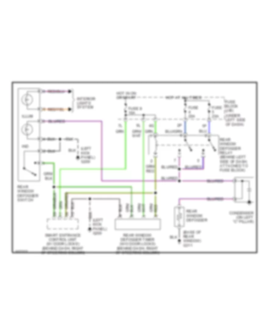
Defogger Wiring Diagram for Nissan Altima GLE 1998
List of elements for Defogger Wiring Diagram for Nissan Altima GLE 1998:
- (base of rear window) g311
- (left kick panel) g200
- (under left side of dash)
- Condenser (on left "c" pillar)
- Fuse 20a
- Fuse 8 10a
- Fuse block (j/b)
- Hot at all times
- Hot in on or start
- Illum
- Ind
- Interior lights system
- Kick panel) g200
- Rear window defogger
- Rear window defogger relay (behind left side of dash, attached to fuse block)
- Rear window defogger switch
- Rear window defogger timer (w/o door locks) (behind dash, right of steering column)
- Smart entrance control unit (w/ door locks) (behind dash, right of steering column)
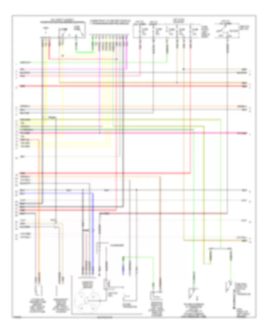
ENGINE PERFORMANCE
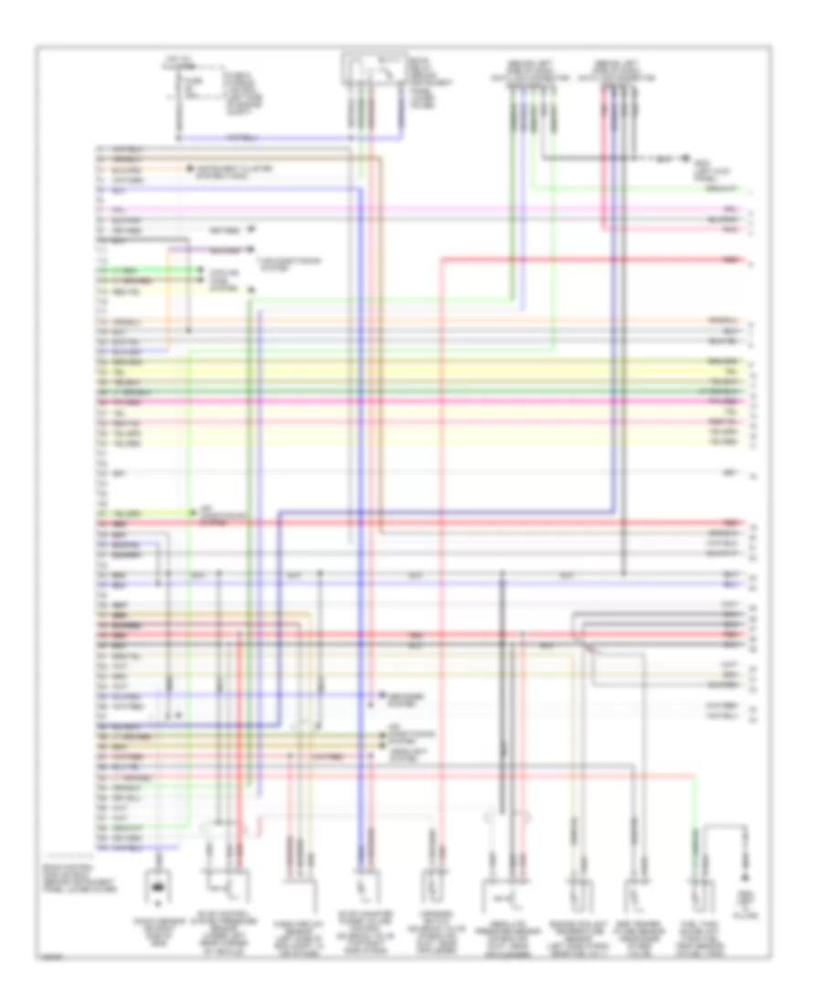
2.4L
2.4L, Engine Performance Wiring Diagrams (1 of 3) for Nissan Altima GLE 1998
List of elements for 2.4L, Engine Performance Wiring Diagrams (1 of 3) for Nissan Altima GLE 1998:
- (behind left side of dash) data link connector (for consult)
- (behind left side of dash) data link connector (for gst)
- Absolute pressure sensor (on eng air duct, near air cleaner)
- Air conditioning system
- Cooling fans system
- Defogger system
- Eccs control module (ecm) (behind instrument panel lower cover)
- Eccs relay (behind instrument panel lower cover)
- Egr temper- ature sensor (near base of egr valve)
- Engine coolant temperature sensor (left side of eng, near fuel inj 1)
- Evap canister purge volume control solenoid valve (top right side of eng)
- Evap control system pressure sensor (under left rear corner of vehicle)
- Fuel tank gauge unit (tank fuel temp sensor) (in fuel tank)
- Fuse & fusible link box (left side of engine compt)
- Fuse 10a
- G202 (left kick panel)
- G904 (left "c" pillar)
- Headlight system
- Hot at all times
- Instrument cluster system (tach)
- Knock sensor (on right side of eng)
- Map/baro switch solenoid valve (on eng air duct, near air clener)
- Mass airflow sensor (left side of eng compt, in air intake)
- Nca
- Nca nca nca
- Pnk
- Red
- Red red red
2.4L, Engine Performance Wiring Diagrams (2 of 3) for Nissan Altima GLE 1998
List of elements for 2.4L, Engine Performance Wiring Diagrams (2 of 3) for Nissan Altima GLE 1998:
- (on throttle body) throttle position sensor & switch
- (under front of center console) transmission control module
- 15k
- A/t
- Acc
- Camshaft position sensor
- Closed
- Condenser
- Crankshaft position sensor (left front of transaxle housing)
- Distributor
- Dropping resistor (left side of eng compt, near air cleaner)
- Fuse 10a
- Fuse 15a
- Fuse block (left side of dash)
- G100 (front of left front fender)
- Hot at all times
- Hot in on or start
- Hot in start
- Ignition coil
- Ignition switch
- Intake air temperature sensor (left side of eng compt, in air intake)
- M/t
- Nca
- Neutral position switch (on transaxle)
- Off
- Pnk
- Power steering oil pressure switch (attached to power steering high pressure tube)
- Power transistor
- Red
- Start
- Wide open
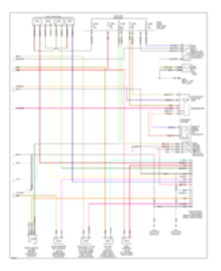
2.4L, Engine Performance Wiring Diagrams (3 of 3) for Nissan Altima GLE 1998
List of elements for 2.4L, Engine Performance Wiring Diagrams (3 of 3) for Nissan Altima GLE 1998:
- 10n
- 13k
- 1o1
- Eccs control module (ecm) (behind instrument panel lower cover)
- Egrc solenoid valve (on top right side of eng)
- Evap canister vent control valve (under left rear corner of vehicle)
- Front heated oxygen sensor (on exhaust manifold)
- Fuel injectors
- Fuel pump (in fuel tank)
- Fuel pump relay (behind left side of dash, attached to fuse block)
- Fuse 10a
- Fuse 15a
- Fuse block (left side of dash)
- G131 (on intake manifold)
- G308 (below left "b" pillar)
- Hot in on or start
- Iacv-aac valve (on right front side of eng, below intake manifold)
- Instrument cluster
- Malfunction indicator lamp
- Nca
- Pnk
- Rear heated oxygen sensor (rear of catalytic converter)
- Red
- Speedometer
- Vacuum cut valve by-pass valve (on evap purge line, between fuel tank & evap canister)
- Vehicle speed sensor (on transaxle)
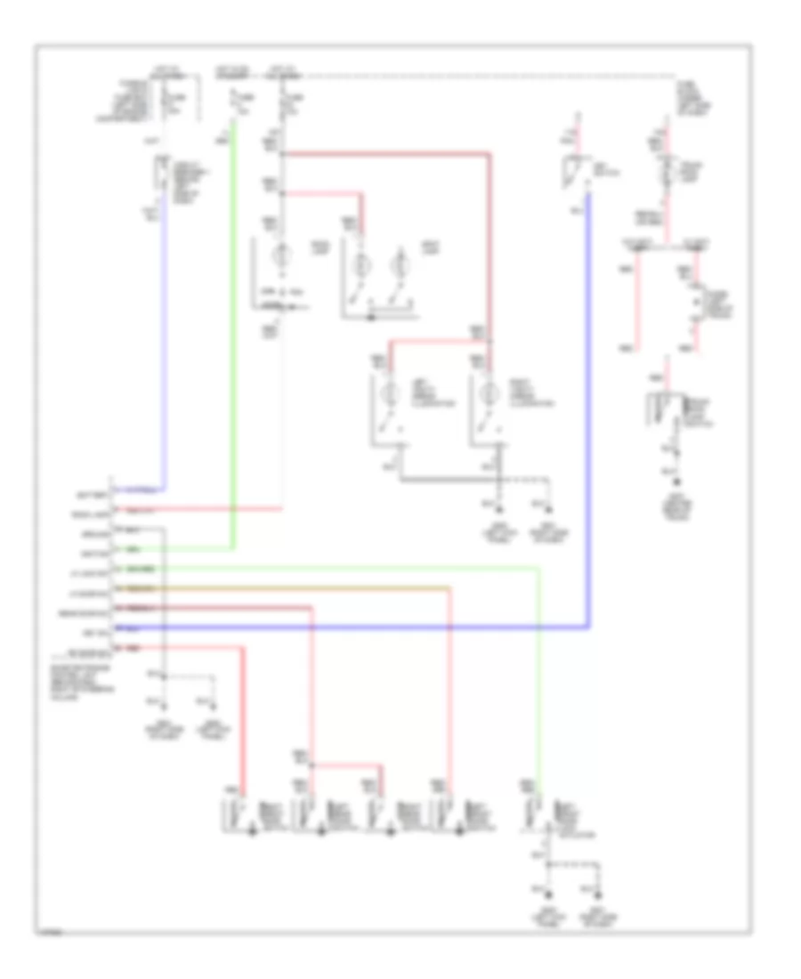
EXTERIOR LIGHTS
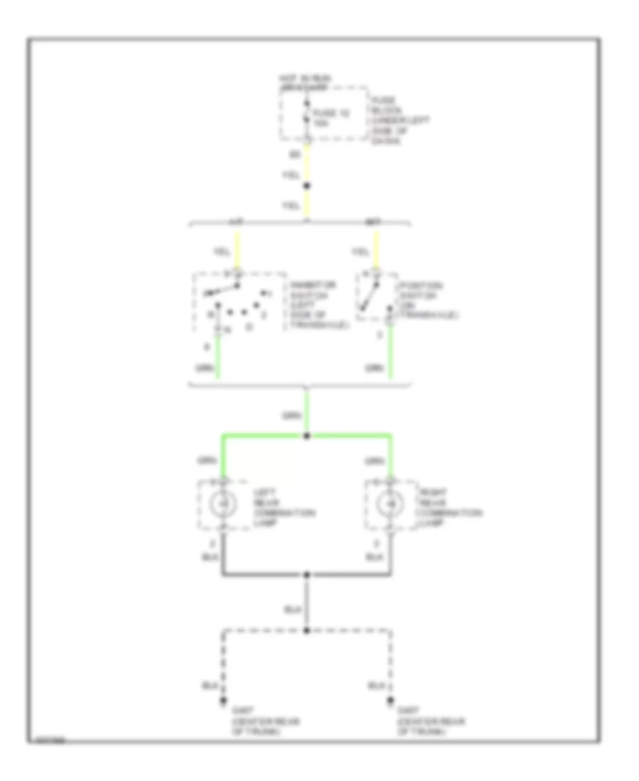
Back-up Lamps Wiring Diagram for Nissan Altima GLE 1998
List of elements for Back-up Lamps Wiring Diagram for Nissan Altima GLE 1998:
- (center rear of trunk)
- A/t
- Fuse 12 10a
- Fuse block (under left side of dash)
- G407
- Hot in run or start
- Inhibitor switch (left side of transaxle)
- Left rear combination lamp
- M/t
- Position switch (on transaxle)
- Right rear combination lamp
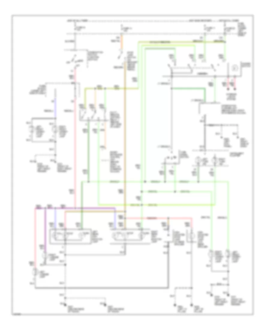
Exterior Lamps Wiring Diagram for Nissan Altima GLE 1998
List of elements for Exterior Lamps Wiring Diagram for Nissan Altima GLE 1998:
- (front of left front fender)
- (front of right front fender)
- (w/ multi-remote)
- 13n
- 16n
- 1st
- 2nd
- Combination flasher unit (behind dash, right of steering column)
- Combination switch (lighting switch)
- Fuse 11 10a
- Fuse 14 15a
- Fuse 20 10a
- Fuse 34 10a
- Fuse block (under left side of dash)
- G100
- G100 (front of left front fender)
- G101
- G101 (front of right front fender)
- G200 (left kick panel)
- G201 (right side of dash)
- G308 (left "b" pillar)
- G407 (center rear of trunk)
- G904 (left "c" pillar)
- Hazard
- Hazard switch
- High mounted stop lamp (w/ rear spoiler)
- High mounted stop lamp (w/o rear spoiler)
- Hot at all times
- Hot in on or start
- Instrument cluster
- Interior lights system
- Left front combin- ation lamp
- Left license lamp
- Left rear com- bination lamp
- Left turn ind
- Multi- remote control relay 1 (behind left side of dash)
- Nca
- Off
- Right front combin- ation lamp
- Right license lamp
- Right rear com- bination lamp
- Right turn ind
- Smart entrance control unit (behind dash, right of steering column)
- Stop
- Stop lamp switch (on bracket above brake pedal)
- Tail
- Turn
- Turn signal switch
GROUND DISTRIBUTION
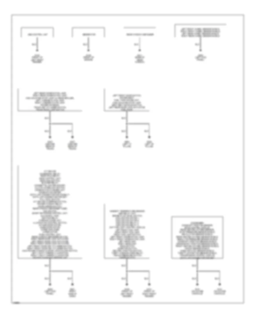
Ground Distribution Wiring Diagram for Nissan Altima GLE 1998
List of elements for Ground Distribution Wiring Diagram for Nissan Altima GLE 1998:
- A/t device, accessory relay, ascd hold relay, ascd control unit, ascd main switch, blower relay, cigarette lighter socket, clutch interlock switch, combination flasher unit, combination meter, data link connector for consult, data link connector for gst, full cool switch, a/t device (override switch), power window relay, door mirror switch, rear window defogger timer, fan switch, smart entrance control unit, glove box lamp, ignition relay, warning chime unit, illumination control switch, intake door motor, mode door motor, wiper amplifier, wiper motor, push control unit, rear window defogger switch, right rear door lock actuator, left front door lock actuator, right front door lock actuator, left front door key cylinder switch, right front door key cylinder switch, main power window & door lock/unlock switch, left vanity mirror illumination, right vanity mirror illumination, air bag diagnosis sensor unit
- Abs control unit
- Ambient temperature sensor, abs relay unit, brake fluid level switch, cooling fan motor 1, cooling fan motor 2, cooling fan relay 2, cooling fan relay 3, daytime light control module, left front fog lamp, right front fog lamp, front fog lamp switch, left front combination lamp, right front combination lamp, left headlamp, right headlamp, hood switch, inhibitor switch, neutral position switch, theft warning horn relay, triple pressure switch wiper switch,
- Condenser, camshaft position sensor, eccs control module, rear heated oxygen sensor, evap pressure sensor shield, revolution sensor shield, rear heated oxygen sensor shield, absolute pressure sensor shield, camshaft position sensor shield, crankshaft position sensor shield, front heated oxygen sensor shield, knock sensor shield, mass air flow sensor shield, throttle position sensor shield, transmission control module,
- Data link connector for gst
- G100 (front of left front fender)
- G101 (front of right front fender)
- G125 (front of engine)
- G131 (on intake manifold)
- G200 (left kick panel)
- G201 (right side of dash)
- G308 (left "b" pillar)
- G311 (base of rear window)
- G407 (center rear of trunk)
- G904 (left "c" pillar)
- Generator
- Left front door switch, power seat, fuel tank gauge unit, high mounted stop lamp, seat belt buckle switch, left rear door lock actuator, fuel pump
- Left front wheel sensor shield, right front wheel sensor shield, left rear wheel sensor shield, right rear wheel sensor shield
- Left rear combination lamp, right rear combination lamp, high mounted stop lamp (w/ rear spoiler), left license plate lamp, right license plate lamp, power antenna, trunk key cylinder switch, trunk room lamp switch
- Rear window defogger
HEADLIGHTS
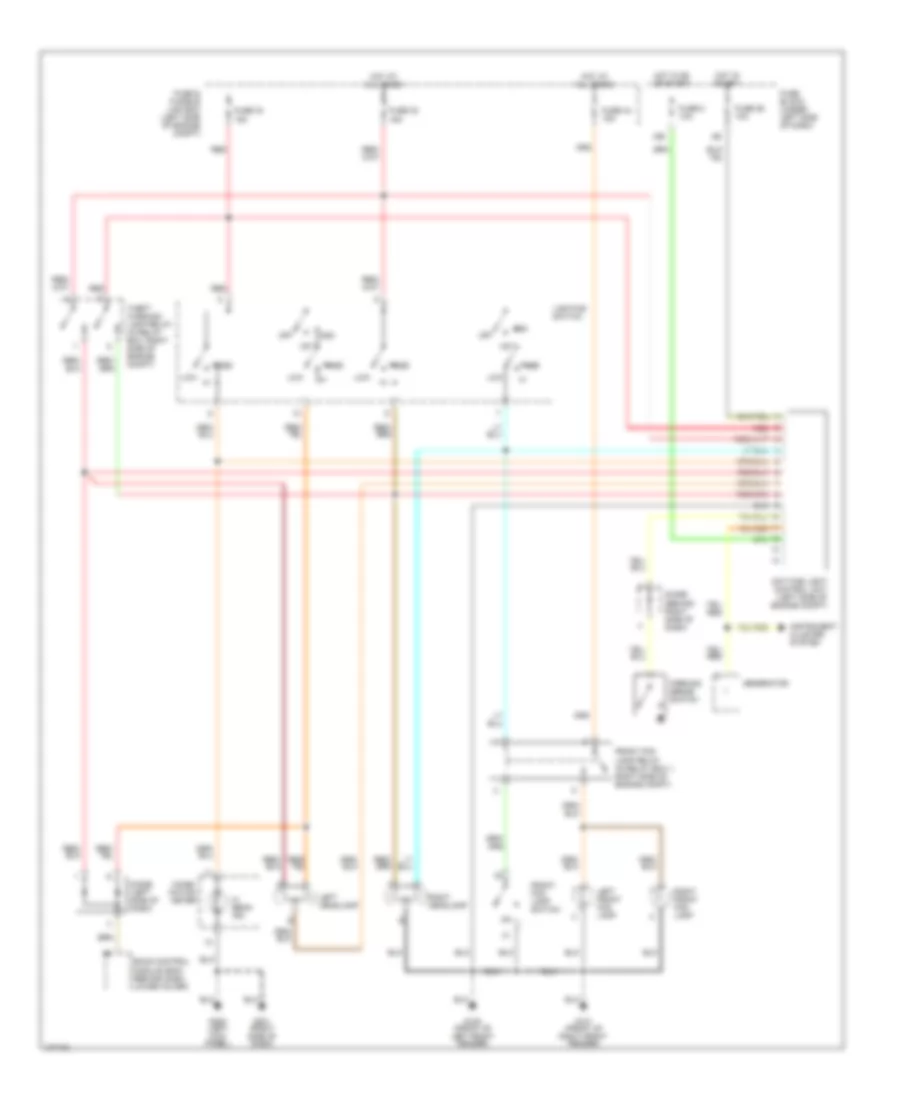
Headlight Wiring Diagram, with DRL for Nissan Altima GLE 1998
List of elements for Headlight Wiring Diagram, with DRL for Nissan Altima GLE 1998:
- 16s
- 1st
- 2nd
- Combi- nation meter
- Daytime light control unit (left side of engine compt)
- Diode (behind right side of dash)
- Diode (left side of dash)
- Eccs control module (ecm) (behind dash lower cover)
- Front fog lamp relay (in relay box 1, right side of engine compt)
- Front fog lamp switch
- Fuse & fusible link box (left side of engine compt)
- Fuse 26 10a
- Fuse 32 15a
- Fuse 33 15a
- Fuse 43 15a
- Fuse 8 10a
- Fuse block (under left side of dash)
- G100 (front of left front fender)
- G101 (front of right front fender)
- G200 (left kick panel)
- G201 (right side of dash)
- Generator
- Hi beam ind
- Hot at all times
- Hot in on or start
- Hot in start
- Instrument cluster system
- Left front fog lamp
- Left headlamp
- Lighting switch
- Low
- Off
- Parking brake switch
- Pass
- Red
- Right front fog lamp
- Right headlamp
- Theft warning lamp relay (in relay box, right side of engine compt)
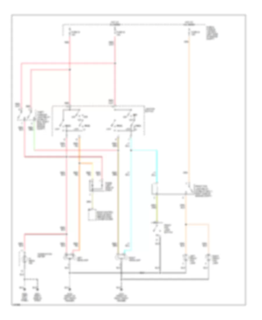
Headlight Wiring Diagram, without DRL for Nissan Altima GLE 1998
List of elements for Headlight Wiring Diagram, without DRL for Nissan Altima GLE 1998:
- 1st
- 2nd
- Combination meter
- Diode (left side of dash)
- Eccs control module (ecm) (behind dash lower cover)
- Front fog lamp relay (in relay box 1, right side of engine compt)
- Front fog lamp switch
- Fuse & fusible link box (left side of engine compt)
- Fuse 32 15a
- Fuse 33 15a
- Fuse 43 15a
- G100 (front of left front fender)
- G101 (front of right front fender)
- G200 (left kick panel)
- G201 (right side of dash)
- Hi beam ind
- Hot at all times
- Left front fog lamp
- Left headlamp
- Lighting switch
- Low
- Off
- Pass
- Red
- Right front fog lamp
- Right headlamp
- Theft warning lamp relay (in relay box, right side of engine compt)
HORN
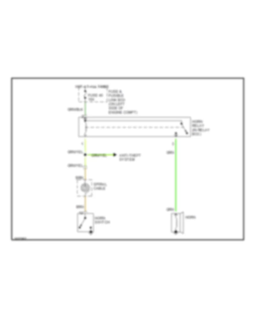
Horn Wiring Diagram for Nissan Altima GLE 1998
List of elements for Horn Wiring Diagram for Nissan Altima GLE 1998:
- Anti-theft system
- Fuse & fusible link box (on left side of engine compt)
- Fuse 40 10a
- Horn
- Horn switch
- Horn relay (in relay box)
- Hot at all times
- Spiral cable
INSTRUMENT CLUSTER
Instrument Cluster Wiring Diagram for Nissan Altima GLE 1998
List of elements for Instrument Cluster Wiring Diagram for Nissan Altima GLE 1998:
- (at base of parking brake lever) parking brake switch
- (behind right side of dash) diode
- (front of left front fender) g100
- (left "c" pillar) g904
- (left side of dash)
- A/t only
- A/t w/ ascd only
- Abs control unit (behind left kick panel)
- Abs ind
- Air bag ind
- Airbag diagnostic sensor unit (below rear of center console)
- Ascd control unit (behind left side of dash)
- Brake fluid level switch (in brake fluid reservoir)
- Brake ind
- Canada
- Charge ind
- Cruise ind
- Door ind
- Ecm (eccs control module) (behind instrument panel lower cover)
- Exterior lights system
- Fuel gauge
- Fuel ind
- Fuel tank gauge unit (in fuel tank)
- Fuse 12 10a
- Fuse block (under left side of dash)
- G203
- G203 (left side of dash)
- G308 (left "b" pillar)
- Generator
- Headlights system
- Hi beam ind
- Hot in on or start
- Illumination (4 bulbs)
- Instrument cluster
- Interior lights system
- Left turn ind
- Malfunction ind light
- Od off ind
- Oil ind
- Oil pressure switch (on right side of engine, near oil filter)
- Right turn ind
- Seat belt buckle switch
- Seat belt ind
- Smart entrance control unit (behind dash, right of steering column)
- Speed- ometer
- Tach- ometer
- Temp. gauge
- Thermal transmitter (upper right rear of engine)
- Transmission control module (under front of center console)
- Usa
- Vehicle speed sensor (on transaxle)
- Warning chime unit (behind dash, right of steering column)
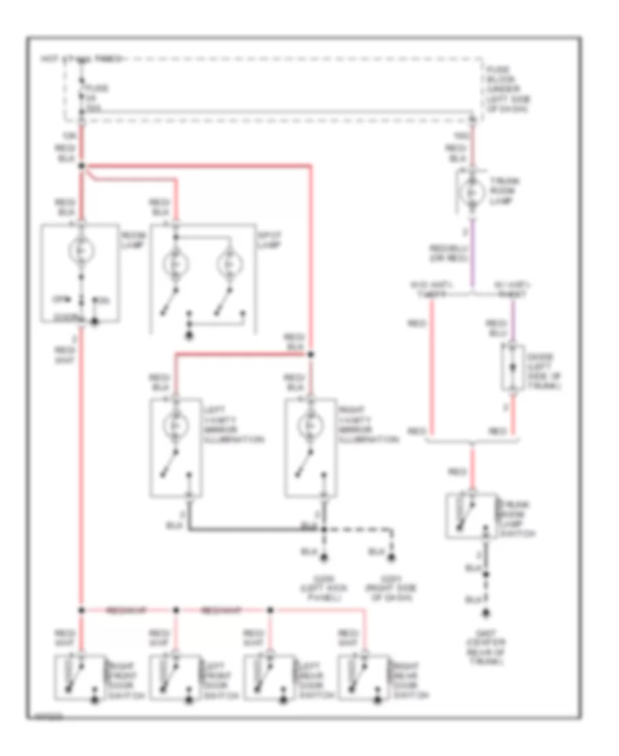
INTERIOR LIGHTS
Courtesy Lamps Wiring Diagram, with Door Locks for Nissan Altima GLE 1998
List of elements for Courtesy Lamps Wiring Diagram, with Door Locks for Nissan Altima GLE 1998:
- 10q
- 11s
- 12k
- Battery
- Circuit breaker 1 (behind left side of dash)
- Closed
- Diode (left side of trunk)
- Door
- Fuse 10a
- Fuse block (under left side of dash)
- Fuse d 40a
- Fusible link & fuse box (left side of engine compartment)
- G200 (left kick panel)
- G201 (right side of dash)
- G407 (center rear of trunk)
- Ground
- Hot at all times
- Hot in on or start
- Ignition
- Key sw
- Key switch
- Left front door lock actuator
- Left front door switch
- Left rear door switch
- Left vanity mirror illumination
- Lf door sw
- Lf lock sw
- Off
- Open
- Pnk
- Rear door sw
- Red
- Rf door sw
- Right front door switch
- Right rear door switch
- Right vanity mirror illumination
- Room lamp
- Smart entrance control unit (behind dash, right of steering column)
- Spot lamp
- Trunk room lamp
- Trunk room lamp switch
- W/ anti- theft
- W/o anti- theft
Courtesy Lamps Wiring Diagram, without Door Locks for Nissan Altima GLE 1998
List of elements for Courtesy Lamps Wiring Diagram, without Door Locks for Nissan Altima GLE 1998:
- 10q
- 12k
- Closed
- Diode (left side of trunk)
- Door
- Fuse 10a
- Fuse block (under left side of dash)
- G200 (left kick panel)
- G201 (right side of dash)
- G407 (center rear of trunk)
- Hot at all times
- Left front door switch
- Left rear door switch
- Left vanity mirror illumination
- Off
- Open
- Red
- Right front door switch
- Right rear door switch
- Right vanity mirror illumination
- Room lamp
- Spot lamp
- Trunk room lamp
- Trunk room lamp switch
- W/ anti- theft
- W/o anti- theft
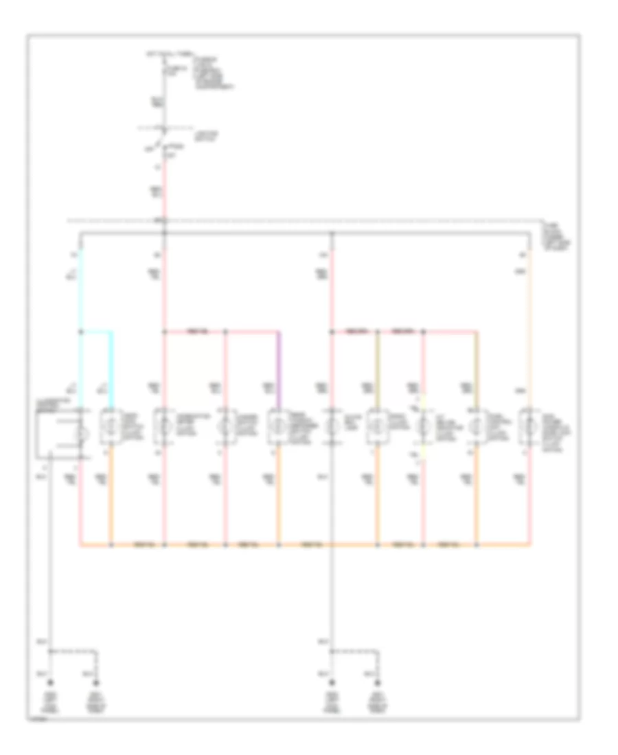
Instrument Illumination Wiring Diagram for Nissan Altima GLE 1998
List of elements for Instrument Illumination Wiring Diagram for Nissan Altima GLE 1998:
- 10k
- 1st
- 2nd
- A/t device indicator (illumi- nation)
- Ascd main switch (illumi- nation)
- Combination meter (illumi- nation)
- Fuse 34 10a
- Fuse block (under left side of dash)
- Fusible link & fuse box (left side of engine compartment)
- G200 (left kick panel)
- G201 (right side of dash)
- Glove box lamp
- Hazard switch (illumi- nation)
- Hot at all times
- Illumination control switch
- Lighting switch
- Main power window & door lock switch (illumi- nation)
- Off
- Push control unit (illumi- nation)
- Radio (illumi- nation)
- Rear window defogger switch (illumi- nation)
POWER ANTENNA
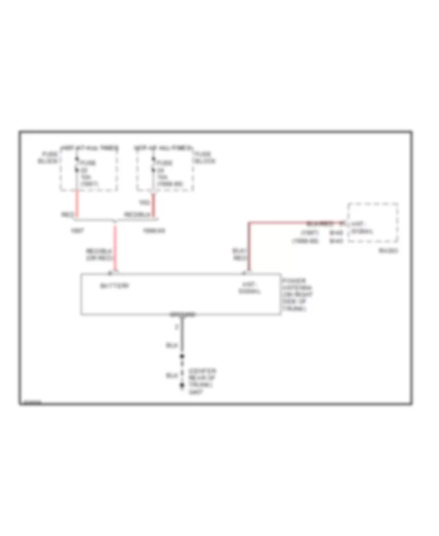
Power Antenna Wiring Diagram for Nissan Altima GLE 1998
List of elements for Power Antenna Wiring Diagram for Nissan Altima GLE 1998:
- (1997)
- (1998-99)
- (center rear of trunk) g407
- 10q
- 1998-99
- Ant- signal
- Battery
- Fuse 10a (1997)
- Fuse 10a (1998-99)
- Fuse block
- Ground
- Hot at all times
- M-40
- M-48
- Power antenna (on right side of trunk)
- Radio
- Red
POWER DISTRIBUTION
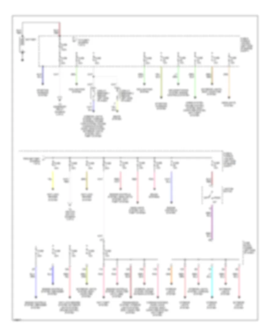
Power Distribution Wiring Diagram (1 of 2) for Nissan Altima GLE 1998
List of elements for Power Distribution Wiring Diagram (1 of 2) for Nissan Altima GLE 1998:
- (diagram 1 of 2)
- 10k
- 10q
- 11k
- 11s
- 12k
- 13n
- 15k
- 16n
- 1st
- 2nd
- Air conditioning system, engine controls system
- Anti-lock brakes
- Anti-lock brakes system, exterior lights system, cruise control system
- Anti-theft system
- Battery
- Circuit breaker 1 (behind left side of dash)
- Circuit breaker 2 (behind left side of dash)
- Cooling fans system
- Engine controls system
- Engine controls system, computer data lines system
- Engine controls system, defogger system
- Engine controls system, headlights system, anti- theft system
- Exterior lights system
- Exterior lights system, body computer system
- Exterior lights, body computer system
- From battery a
- Fuse & fusible link box (left side of engine compt)
- Fuse 10a
- Fuse 15a
- Fuse 20a
- Fuse a 80a
- Fuse b 40a
- Fuse block (under left side of dash)
- Fuse c 40a
- Fuse d 40a
- Fuse e 100a
- Fuse f 40a
- Fuse g 40a
- Fuse h 40a
- Fuse j 50a
- Headlights system
- Headlights system, anti- theft system
- Horns system, cruise control system, body computer system, anti-theft system
- Interior lights system
- Interior lights system, power antenna system
- Interior lights system, warning system
- Interior lights system, warning systems, power tops system, power windows system, door locks system, exterior lights system, anti- theft system
- Lighting switch
- Off
- Pnk
- Red
- Seats system
- Sound systems
- Starting/ charging system
- System
- To accessory relay (diagram 2 of 2)
- To fuse f (diagram 1 of 2)
- To ignition switch (diagram 2 of 2)
- Transmission system, interior lights system, body computer system
- Warning systems, door locks system, body computer system, anti-theft system
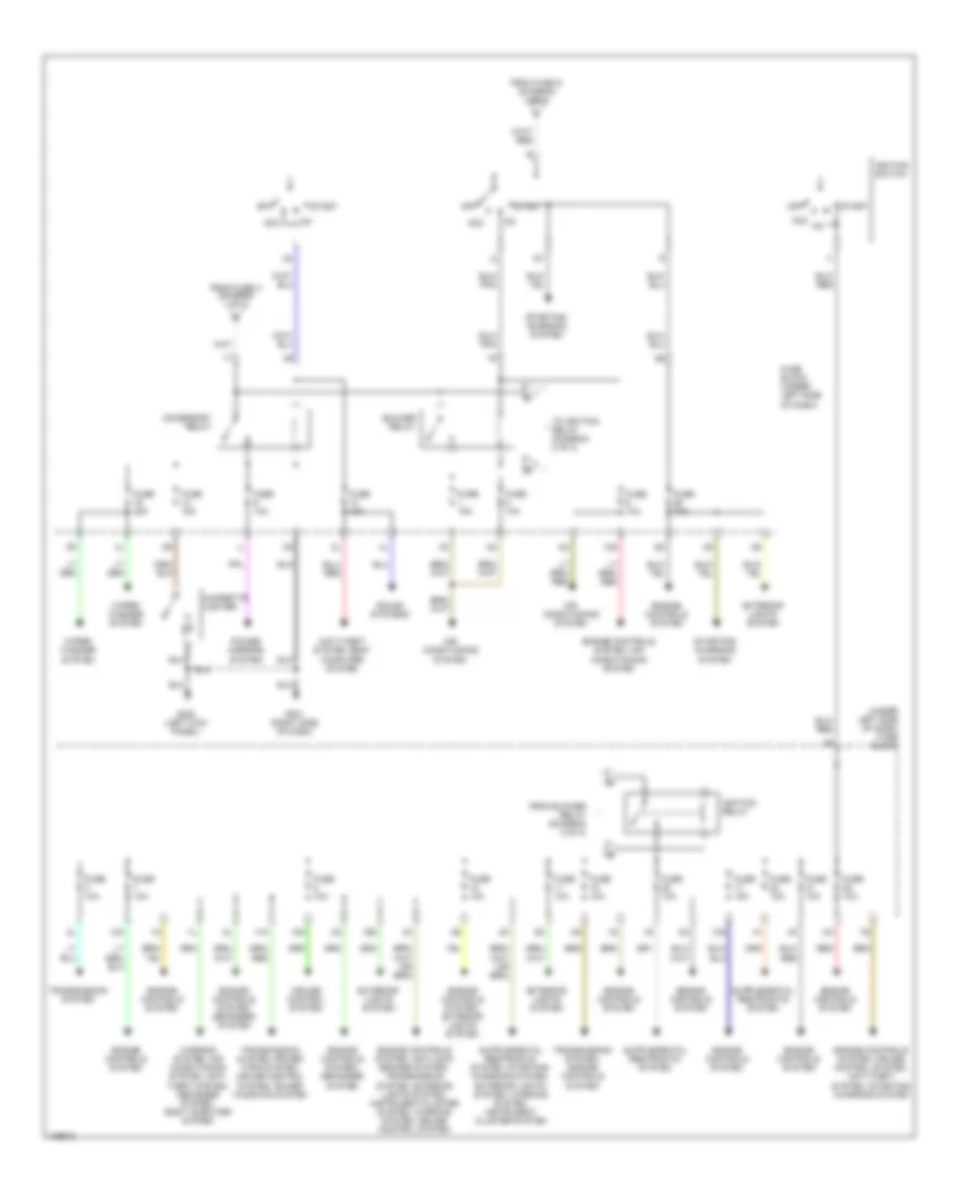
Power Distribution Wiring Diagram (2 of 2) for Nissan Altima GLE 1998
List of elements for Power Distribution Wiring Diagram (2 of 2) for Nissan Altima GLE 1998:
- (under left side of dash) fuse block
- 10n
- 10s
- 11n
- 12n
- 13k
- 16s
- Acc
- Acc on
- Accessory relay
- Air conditioning system
- Anti-theft system, body computer system
- Blower relay
- Cigarette lighter
- Cruise control system
- Engine controls system
- Engine controls system, air conditioning system
- Engine controls system, anti-lock brakes system, transmission system, exterior lights system, instrument cluster system, warning system, cruise control system
- Engine controls system, cruise control system, anti-theft system, starting/ charging system
- Engine controls system, defogger system
- Engine controls system, exterior lights system
- Exterior lights system
- From blower relay (diagram 2 of 2)
- From fuse a (diagram 1 of 2)
- From fuse g (diagram 1 of 2)
- Fuse 10a
- Fuse 15a
- Fuse 20a
- Fuse block (under left side of dash)
- G200 (left kick panel)
- G201 (right side of dash)
- Ignition relay
- Ignition switch
- Off
- Power mirrors system
- Red
- Sound systems
- Start
- Starting/ charging system
- To ignition relay (diagram 2 of 2)
- Transmission system
- Transmission system, engine controls system
- Transmission system, power tops system, cruise control system, power windows system
- Warning system, air conditioning system, anti- theft system, defogger system, body computer system
- Wiper/ washer system
POWER DOOR LOCKS
Power Door Lock Wiring Diagram for Nissan Altima GLE 1998
List of elements for Power Door Lock Wiring Diagram for Nissan Altima GLE 1998:
- 11s
- Bat
- Circuit breaker 1 (behind left side of dash)
- Full stroke lock
- Full stroke unlock
- Fuse 10a
- Fuse 7.5a
- Fuse block (under left side of dash)
- G200 (left kick panel)
- G201 (right side of dash)
- G308 (left "b" pillar)
- G904 (left "c" pillar)
- Ground
- Hot at all times
- Hot in on or start
- Ign
- Key cyl sw
- Key sw
- Key switch
- L door sw
- Left door key cylinder switch
- Left front door lock actuator
- Left front door switch
- Left rear door lock actuator
- Lock
- Lock output
- Main power window & door lock/ unlock switch
- Mid stroke
- Pnk
- R door sw
- Red
- Right door key cylinder switch
- Right front door lock actuator
- Right front door switch
- Right rear door lock actuator
- Smart entrance control unit (behind dash, right of steering column)
- Unlock
- Unlock output
- Unlock sense
- W multi- remote system
- W/o multi- remote system
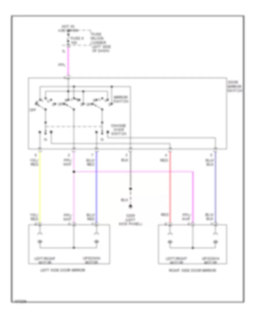
POWER MIRRORS
Power Mirror Wiring Diagram for Nissan Altima GLE 1998
List of elements for Power Mirror Wiring Diagram for Nissan Altima GLE 1998:
- Change over switch
- Door mirror switch
- Fuse 9 10a
- Fuse block (under left side of dash)
- G200 (left kick panel)
- Hot in acc or on
- Left side door mirror
- Left/right motor
- Mirror switch
- Off
- Red
- Right side door mirror
- Up/down motor
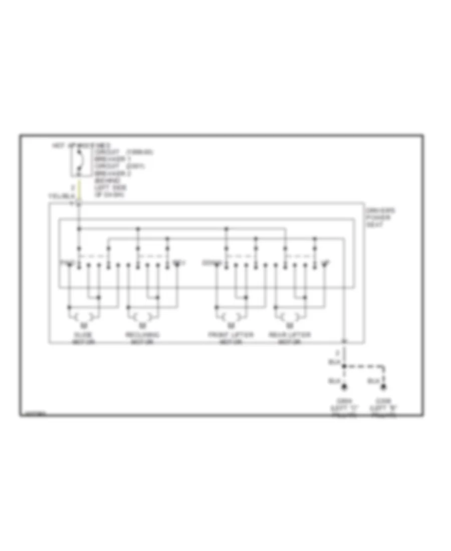
POWER SEATS
Driver Seat Wiring Diagram for Nissan Altima GLE 1998
List of elements for Driver Seat Wiring Diagram for Nissan Altima GLE 1998:
- (1998-00)
- (2001)
- Circuit breaker 1 circuit breaker 2 (behind left side of dash)
- Down
- Driver's power seat
- Front lifter motor
- Fwd
- G308 (left "b" pillar)
- G904 (left "c" pillar)
- Hot at all times
- Rear lifter motor
- Reclining motor
- Rev
- Slide motor
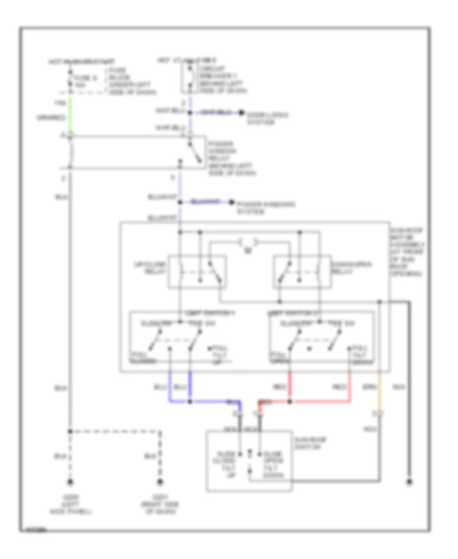
POWER TOP/SUNROOF
Power Top/Sunroof Wiring Diagrams for Nissan Altima GLE 1998
List of elements for Power Top/Sunroof Wiring Diagrams for Nissan Altima GLE 1998:
- 11n
- Circuit breaker 1 (behind left side of dash)
- Closed
- Door locks system
- Down/open relay
- Full
- Full open
- Full tilt down
- Full tilt up
- Fuse 8 10a
- Fuse block (under left side of dash)
- G200 (left kick panel)
- G201 (right side of dash)
- Hot at all times
- Hot in on or start
- Limit switch 1
- Limit switch 2
- Nca
- Power window relay (behind left side of dash)
- Power windows system
- Red
- Slide close/ tilt up
- Slide open/ tilt down
- Slide sw
- Sun roof motor assembly (at front of sun roof opening)
- Sun roof switch
- Tilt sw
- Up/close relay
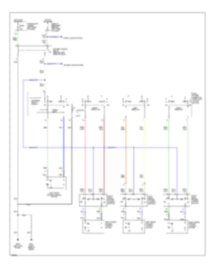
POWER WINDOWS
Power Window Wiring Diagram for Nissan Altima GLE 1998
List of elements for Power Window Wiring Diagram for Nissan Altima GLE 1998:
- 11n
- Circuit breaker 1 (behind left side of dash)
- Door locks system
- Express down circuit
- Front left
- Front sw
- Fuse 10a
- Fuse block (under left side of dash)
- G200 (left kick panel)
- G201 (right side of dash)
- Hot at all times
- Hot in on or start
- Left
- Left front power window motor
- Left rear power window motor
- Left rear power window switch
- Lock
- Lock sw
- Main power window & door lock/ unlock switch
- Nca
- Power tops system
- Power window relay (behind left side of dash)
- Rear sw
- Right
- Right front power window motor
- Right front power window switch
- Right rear power window motor
- Right rear power window switch
- Unlock
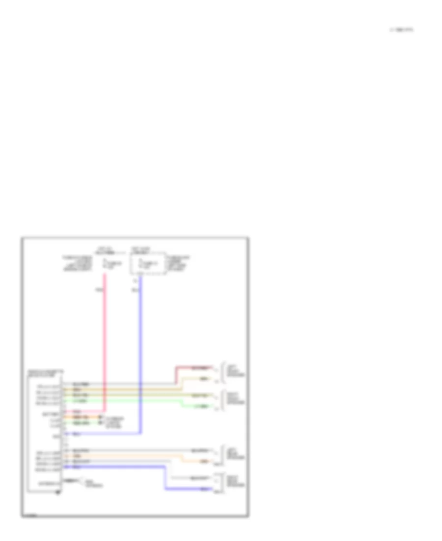
RADIO
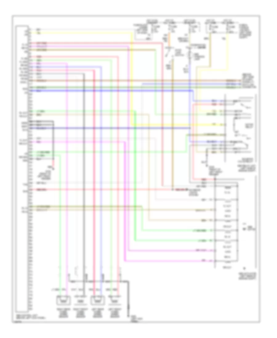
Base Model for Nissan Altima GLE 1998
List of elements for Base Model for Nissan Altima GLE 1998:
- (+)
- (-)
- Acc
- Antenna in
- Battery
- C 1996 vftc
- Fr lh (+) out
- Fr lh (-) out
- Fr rh (+) out
- Fr rh (-) out
- Fuse & fusible link box (left side of engine compt)
- Fuse 10 10a
- Fuse 35 10a
- Fuse block (under left side of dash)
- Hot at all times
- Hot in on or acc
- Illum
- Interior lights system
- Left front speaker
- Left rear speaker
- Nca
- Pnk
- Radio & cassette or cd player
- Right front speaker
- Right rear speaker
- Rod antenna
- Rr lh (+) amp
- Rr lh (-) amp
- Rr rh (+) amp
- Rr rh (-) amp
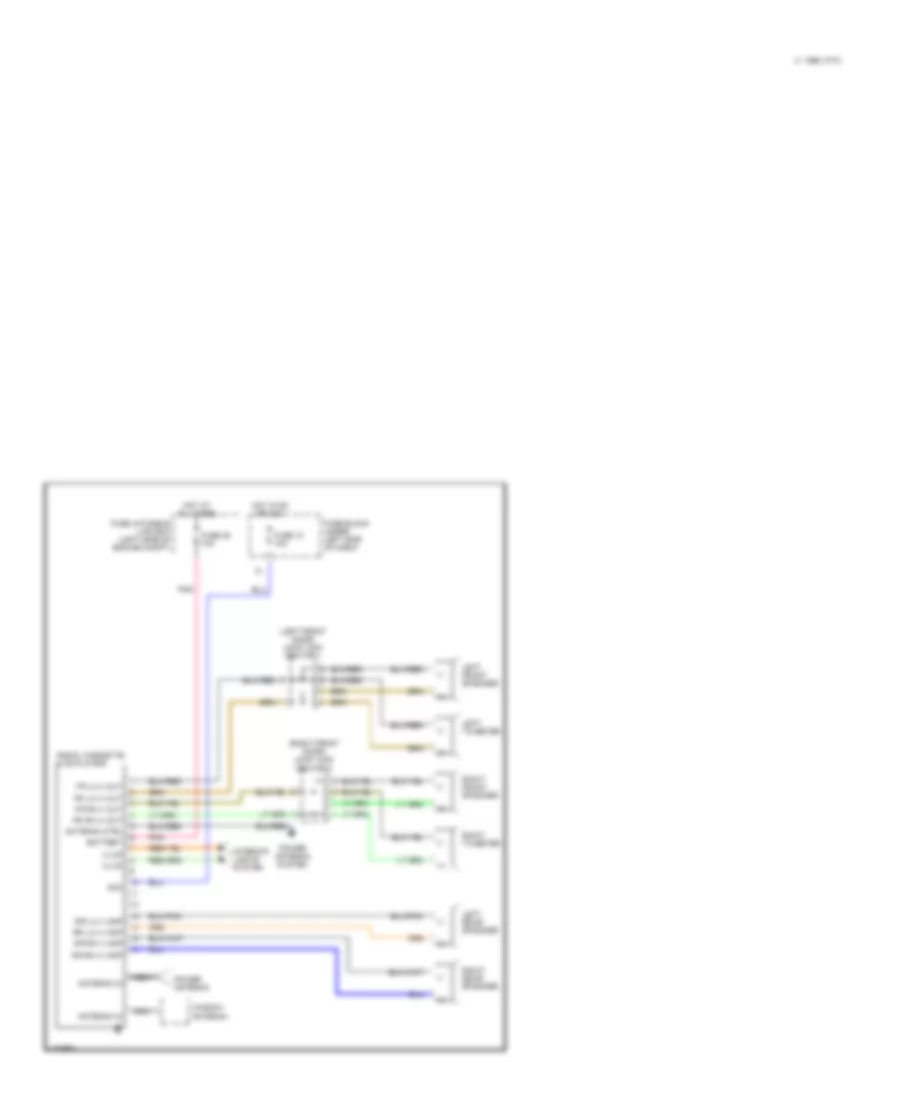
Premium Sound Radio Wiring Diagram for Nissan Altima GLE 1998
List of elements for Premium Sound Radio Wiring Diagram for Nissan Altima GLE 1998:
- (+)
- (-)
- (left front door) joint con- nector 1
- (right front door) joint con- nector 2
- Acc
- Antenna ctrl
- Antenna in
- Battery
- C 1996 vftc
- Fr lh (+) out
- Fr lh (-) out
- Fr rh (+) out
- Fr rh (-) out
- Fuse & fusible link box (left side of engine compt)
- Fuse 10 10a
- Fuse 35 10a
- Fuse block under left side of dash)
- Hot at all times
- Hot in on or acc
- Illum
- Interior lights system
- Left front speaker
- Left rear speaker
- Left tweeter
- Nca
- Pnk
- Power antenna
- Power antenna system
- Radio, cassette & cd player
- Right front speaker
- Right rear speaker
- Right tweeter
- Rr lh (+) amp
- Rr lh (-) amp
- Rr rh (+) amp
- Rr rh (-) amp
- Window antenna
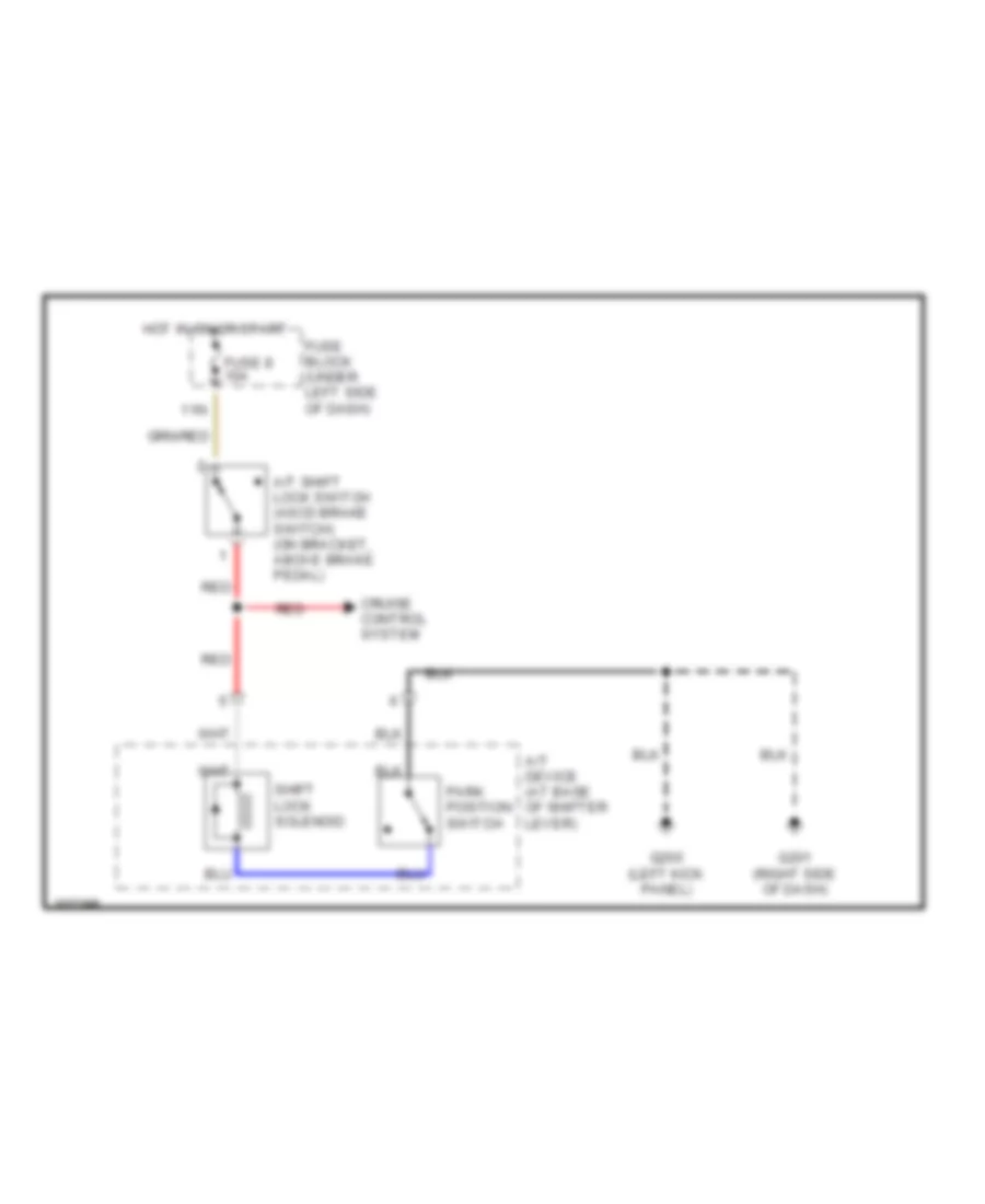
SHIFT INTERLOCKS
Shift Interlock Wiring Diagram for Nissan Altima GLE 1998
List of elements for Shift Interlock Wiring Diagram for Nissan Altima GLE 1998:
- 11n
- A/t device (at base of shifter lever)
- A/t shift lock switch (ascd brake switch) (on bracket, above brake pedal)
- Cruise control system
- Fuse 8 10a
- Fuse block (under left side of dash)
- G200 (left kick panel)
- G201 (right side of dash)
- Hot in on or start
- Park position switch
- Red
- Shift lock solenoid
STARTING/CHARGING
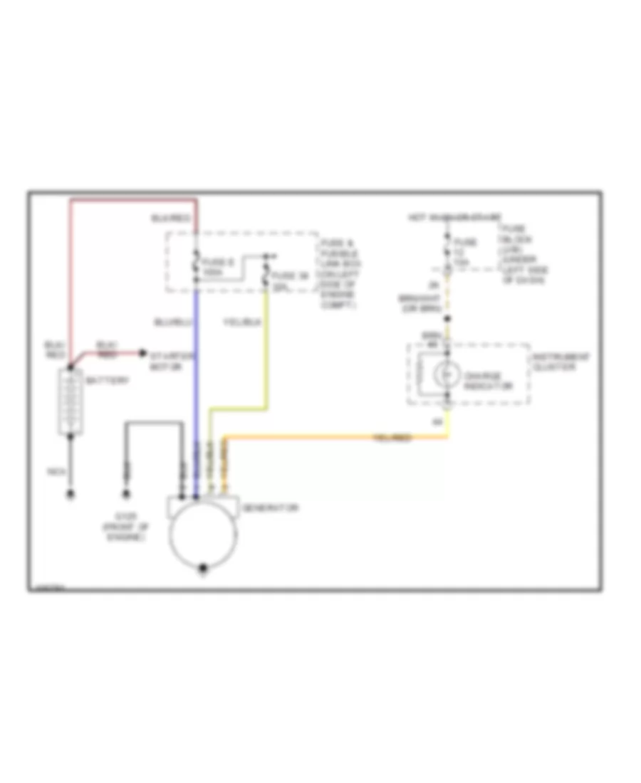
Charging Wiring Diagram for Nissan Altima GLE 1998
List of elements for Charging Wiring Diagram for Nissan Altima GLE 1998:
- Battery
- Charge indicator
- Fuse & fusible link box (on left side of engine compt)
- Fuse 10a
- Fuse 38 10a
- Fuse block (j/b) (under left side of dash)
- Fuse e 100a
- G125 (front of engine)
- Generator
- Hot in on or start
- Instrument cluster
- Nca
- Starter motor
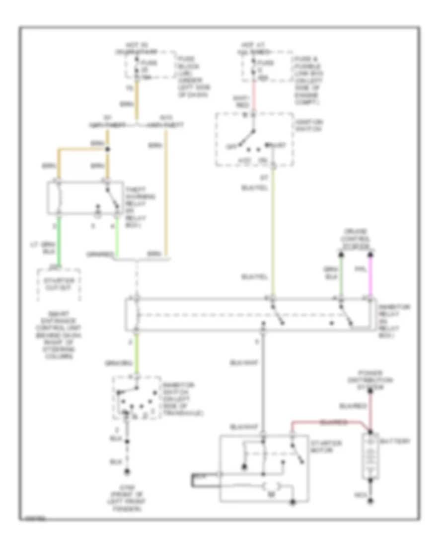
Starting Wiring Diagram, A/T for Nissan Altima GLE 1998
List of elements for Starting Wiring Diagram, A/T for Nissan Altima GLE 1998:
- Acc
- Battery
- Cruise control system
- Fuse & fusible link box (on left side of engine compt)
- Fuse 10a
- Fuse block (j/b) (under left side of dash)
- Fuse g 40a
- G100 (front of left front fender)
- Hot at all times
- Hot in on or start
- Ignition switch
- Inhibitor relay (in relay box)
- Inhibitor switch (on left side of transaxle)
- Nca
- Off
- Power distribution system
- Smart entrance control unit (behind dash, right of steering column)
- Start
- Starter cutout
- Starter motor
- Theft warning relay (in relay box)
- W/ anti-theft
- W/o anti-theft
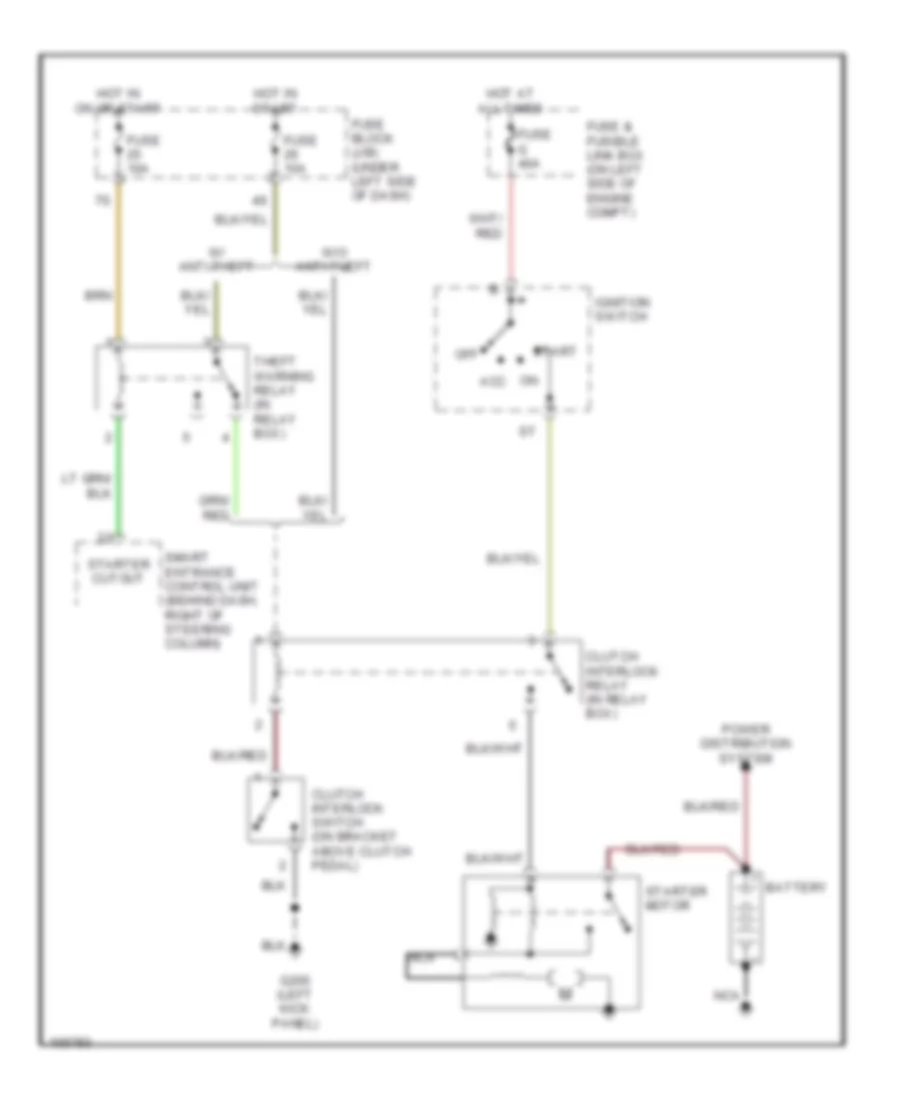
Starting Wiring Diagram, M/T for Nissan Altima GLE 1998
List of elements for Starting Wiring Diagram, M/T for Nissan Altima GLE 1998:
- Acc
- Battery
- Clutch interlock relay (in relay box)
- Clutch interlock switch (on bracket above clutch pedal)
- Fuse & fusible link box (on left side of engine compt)
- Fuse 10a
- Fuse block (j/b) (under left side of dash)
- Fuse g 40a
- G200 (left kick panel)
- Hot at all times
- Hot in on or start
- Hot in start
- Ignition switch
- Nca
- Off
- Power distribution system
- Smart entrance control unit (behind dash, right of steering column)
- Start
- Starter cutout
- Starter motor
- Theft warning relay (in relay box)
- W/ anti-theft
- W/o anti-theft
SUPPLEMENTAL RESTRAINTS
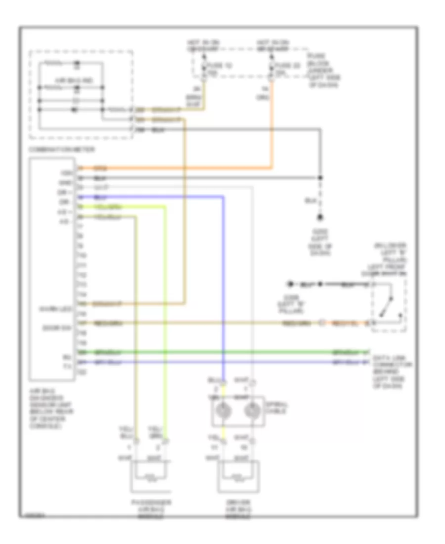
Supplemental Restraint Wiring Diagram for Nissan Altima GLE 1998
List of elements for Supplemental Restraint Wiring Diagram for Nissan Altima GLE 1998:
- (in lower left "b" pillar) left front door switch
- Air bag diagnosis sensor unit (below rear of center console)
- Air bag ind.
- As +
- As -
- Combination meter
- Data link connector (behind left side of dash)
- Door sw
- Dr +
- Dr -
- Driver air bag module
- Fuse 12 10a
- Fuse 22 10a
- Fuse block (under left side of dash)
- G202 (left side of dash)
- G308 (left "b" pillar)
- Gnd
- Hot in on or start
- Ign
- Passenger air bag module
- Spiral cable
- Warn led
TRANSMISSION
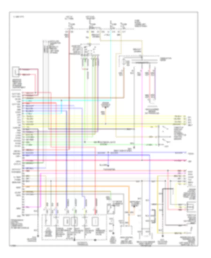
A/T Wiring Diagram for Nissan Altima GLE 1998
List of elements for A/T Wiring Diagram for Nissan Altima GLE 1998:
- 1 pos
- 12k
- 1995 vftc c
- 2 pos
- A/t device (overdrive switch)
- A/t fluid temper- ature sensor
- All times
- Ascd
- Ascd control unit (behind left side of dash)
- Atck
- Automatic transaxle
- Avcc
- Clsd sw
- Cluster system
- Combination meter
- D pos
- Data in
- Data link connector (for consult) (behind left side of dash)
- Data out
- Dropping resistor (left side of engine compartment)
- Dt1
- Dt2
- Dt3
- Duty sol
- E60
- Eng rev
- Engine control module (ecm) (behind instr panel lower cover)
- Engine controls system
- Engine coolant temperature sensor (left side of eng, near fuel inj 1)
- Exterior lights system
- Fl temp
- Fuse 10a
- Fuse block (under left side of dash)
- G131 (on intake manifold)
- G201 (right side of dash)
- Gnd
- Gnd-a
- Hot at
- Hot in on or start
- Inhibitor switch (on left side of transaxle)
- Instrument
- Line pressure solenoid valve
- M17
- M18
- M20
- Mem b/u
- Nca
- Neut
- O/d off ind
- Obd2
- Od ind
- Od off
- Over- run clutch solen- oid valve
- Ovr/c
- P/n pos
- Pwr sens
- R pos
- Red
- Revolution sensor (right rear of transaxle)
- Sens gnd
- Shift solenoid valve a
- Shift solenoid valve b
- Speedometer
- Ssa
- Ssb
- Tacho
- Tachometer
- Th/sen
- Throttle position sensor (on throttle body)
- Throttle position switch (integral to throttle position sensor)
- Torque converter clutch solenoid valve
- Transmission control module (tcm) (under front of center console)
- Tvo
- Tvo1
- Vehicle speed sensor (on transaxle)
- Vign
- Vsp
- Vsp-1
- Vsp-2
- W/tmp
- Wo sw
- Wot
WARNING SYSTEMS
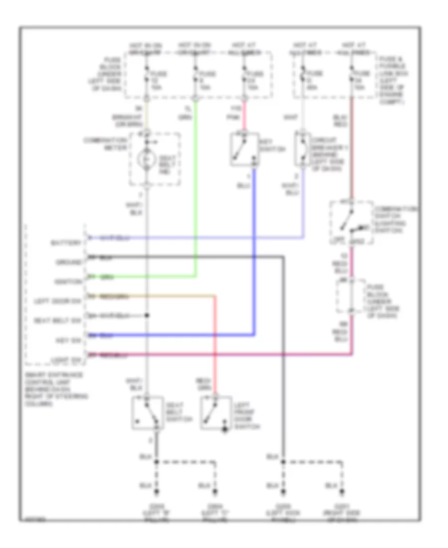
Warning System Wiring Diagrams, with Door Locks for Nissan Altima GLE 1998
List of elements for Warning System Wiring Diagrams, with Door Locks for Nissan Altima GLE 1998:
- 11s
- 1st
- 2nd
- Battery
- Circuit breaker 1 (behind left side of dash)
- Combination meter
- Combination switch (lighting switch)
- Fuse & fusible link box (left side of engine compt)
- Fuse 10a
- Fuse block (under left side of dash)
- Fuse d 40a
- G200 (left kick panel)
- G201 (right side of dash)
- G308 (left "b" pillar)
- G904 (left "c" pillar)
- Ground
- Hot at all times
- Hot in on or start
- Ignition
- Key sw
- Key switch
- Left door sw
- Left front door switch
- Light sw
- Off
- Pnk
- Seat belt ind.
- Seat belt sw
- Seat belt switch
- Smart entrance control unit (behind dash, right of steering column)
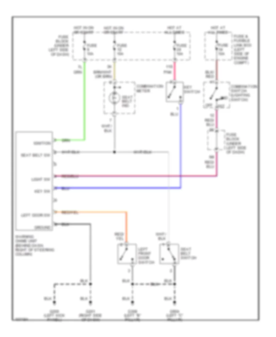
Warning System Wiring Diagrams, without Door Locks for Nissan Altima GLE 1998
List of elements for Warning System Wiring Diagrams, without Door Locks for Nissan Altima GLE 1998:
- 11s
- 1st
- 2nd
- Combination meter
- Combination switch (lighting switch)
- Fuse & fusible link box (left side of engine compt)
- Fuse 10a
- Fuse block (under left side of dash)
- G200 (left kick panel)
- G201 (right side of dash)
- G308 (left "b" pillar)
- G904 (left "c" pillar)
- Ground
- Hot at all times
- Hot in on or start
- Ignition
- Key sw
- Key switch
- Left door sw
- Left front door switch
- Light sw
- Off
- Pnk
- Seat belt ind.
- Seat belt sw
- Seat belt switch
- Warning chime unit (behind dash, right of steering column)
WIPER/WASHER
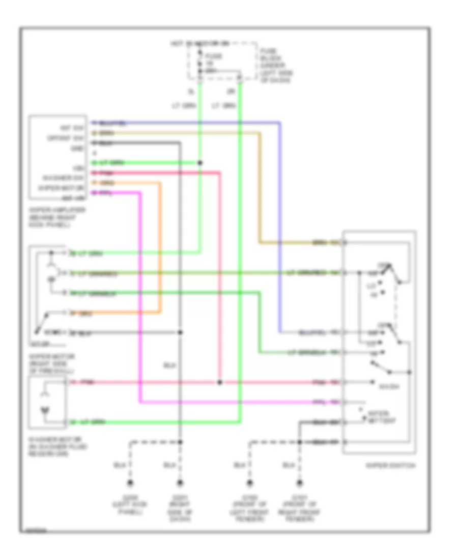
Wiper/Washer Wiring Diagram for Nissan Altima GLE 1998
List of elements for Wiper/Washer Wiring Diagram for Nissan Altima GLE 1998:
- Fuse 20a
- Fuse block (under left side of dash)
- G100 (front of left front fender)
- G101 (front of right front fender)
- G200 (left kick panel)
- G201 (right side of dash)
- Gnd
- Hot in acc or on
- Ign
- Int
- Int sw
- Int vr
- Inter- mittent
- Move
- Off
- Off/int sw
- Pnk
- Stop
- Wash
- Washer motor (in washer fluid reservoir)
- Washer sw
- Wiper amplifier (behind right kick panel)
- Wiper motor
- Wiper motor (right side of firewall)
- Wiper switch

 Čeština
 Dansk
Dansk Deutsch
 English
 English
 Español
 Suomi
Suomi Français
 Français
 עברית
עברית Hrvatski
 Magyar
 Italiano
 日本語
日本語 한국어
한국어 Nederlands
 Polski
 Português
 Português
 Română
 Русский
 Slovenčina
 Slovenščina
 Svenska
 Türkçe
 中文 (中国)