AIR CONDITIONING
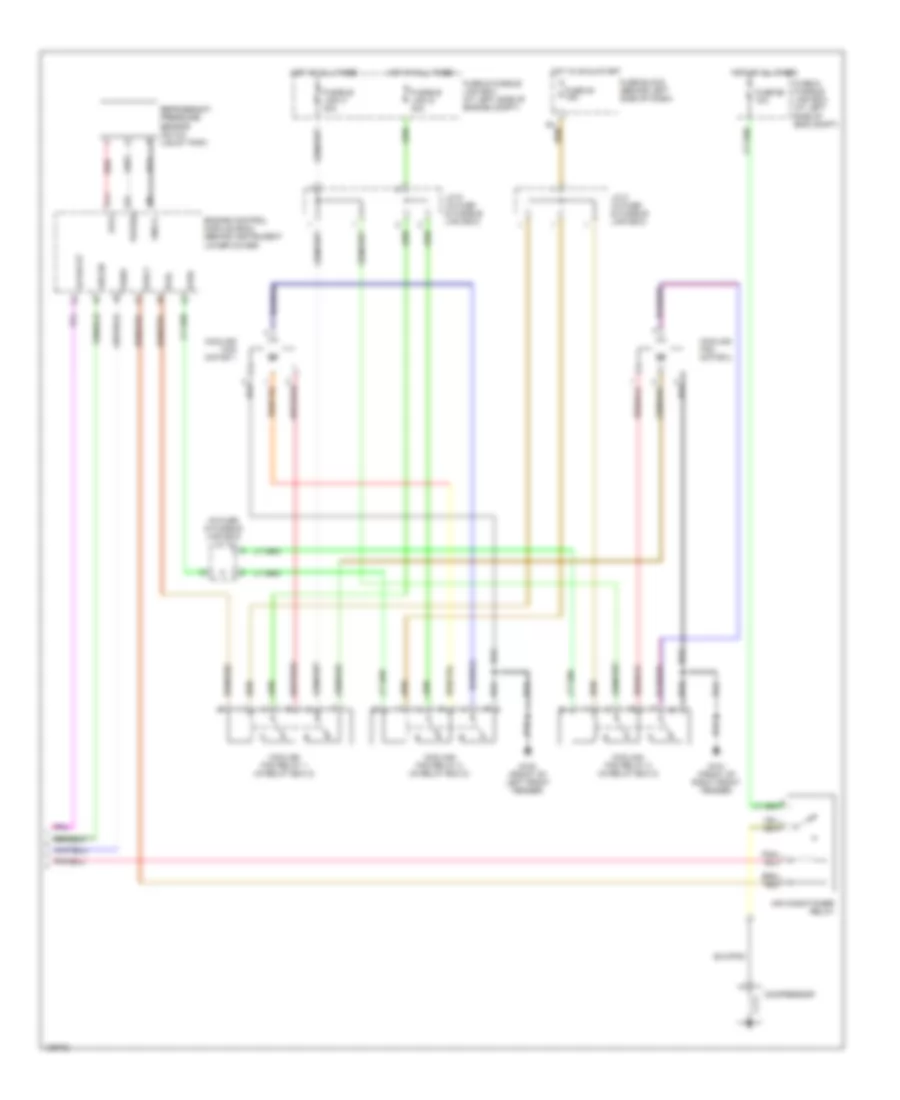
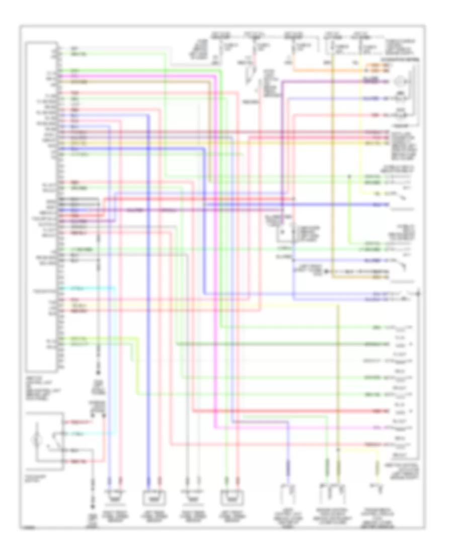
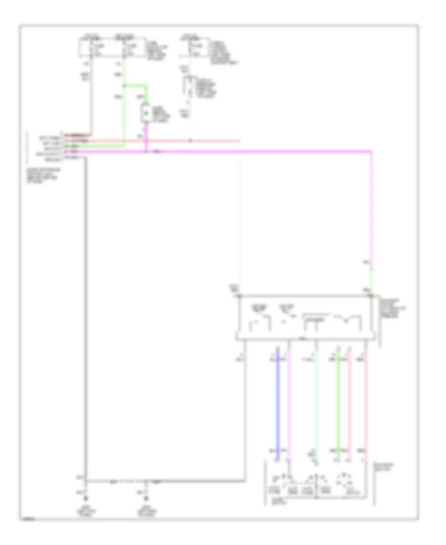
Automatic A/C Wiring Diagram (1 of 2) for Nissan Maxima GLE 2000
 https://portal-diagnostov.com/license.html
Automotive Electricians Portal FZCO
Automotive Electricians Portal FZCO
https://portal-diagnostov.com/license.html
https://portal-diagnostov.com/license.html
Automotive Electricians Portal FZCO
Automotive Electricians Portal FZCO
List of elements for Automatic A/C Wiring Diagram (1 of 2) for Nissan Maxima GLE 2000:
- (behind center
- (behind right
- (near right
- (on right
- 10k
- A/c auto amplifier (behind center of dash)
- Acc
- Air mix door motor (behind center of dash)
- Amb sens
- Bat
- Blower motor (behind right side of dash)
- Blower motor relay (behind right side of dash)
- Cel/fht
- Comp
- Defogger system
- Defroster grille) sunload
- Ecm comp
- Fan control amplifier (behind right side of dash)
- Fan f/b
- Fan gate
- Ficd
- Front corner of vehicle) ambient sensor
- Fuse & fusible link box (at left side of eng compt)
- Fuse 10a
- Fuse 15a
- Fuse block (behind left side of dash)
- G100 (front of left front fender)
- G201 (right side of dash)
- G202 (left side of dash)
- Grd
- Hot at all times
- Hot in on
- Ign
- Ign 2
- Ignition switch
- Ill
- In-vehicle sensor
- Incar sens
- Intake door motor (behind right side of dash)
- Intake sens
- Interior lights system
- J/c 7 (in fuse & fusible link box)
- Lan-sig
- Light
- Lock
- M59
- M60
- Mode door motor (behind center of dash)
- Of dash)
- Or start
- Red
- Rr def f/b
- Rr def on
- Run
- Sens grd
- Sensor
- Side of dash) intake sensor
- Start
- Sun sens
- Thermal transmitter (on top left rear of engine)
- Vactr
- W/t sens
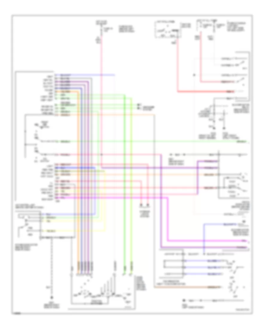
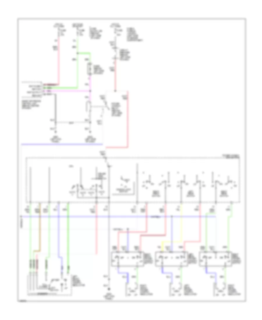
Automatic A/C Wiring Diagram (2 of 2) for Nissan Maxima GLE 2000
List of elements for Automatic A/C Wiring Diagram (2 of 2) for Nissan Maxima GLE 2000:
- (in fuse & fusible link box) j/c 10
- Acpdcut
- Acrly
- Air conditioner relay
- Arcon
- Avcc
- Compressor
- Cooling fan motor 1
- Cooling fan motor 2
- Cooling fan relay 1 (in relay box 2)
- Cooling fan relay 2 (in relay box 2)
- Cooling fan relay 3 (in relay box 2)
- Engine control module (ecm) (behind instrument lower cover)
- Fuse & fusible link box (at left side of eng compt)
- Fuse & fusible link box (at left side of engine compt)
- Fuse 20 15a
- Fuse 66 10a
- Fuse block (behind left side of dash)
- Fusible link g 40a
- Fusible link h 40a
- G100 (front of left front fender)
- G101 (front of right front fender)
- Gnd-a
- Hot at all times
- Hot in on & start
- J/c 8 (in fuse & fusible link box)
- J/c 9 (in fuse & fusible link box)
- Pdpres
- Red
- Refrigerant pressure sensor (on a/c liquid tank)
- Rfrh
- Rfrl
- Tasw
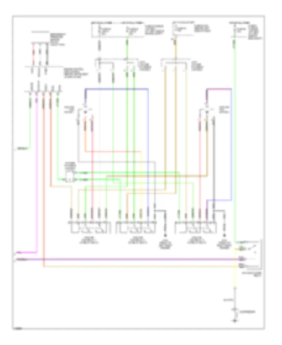
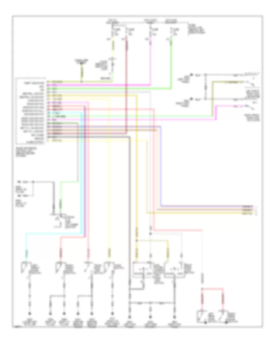
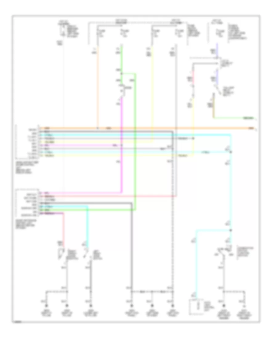
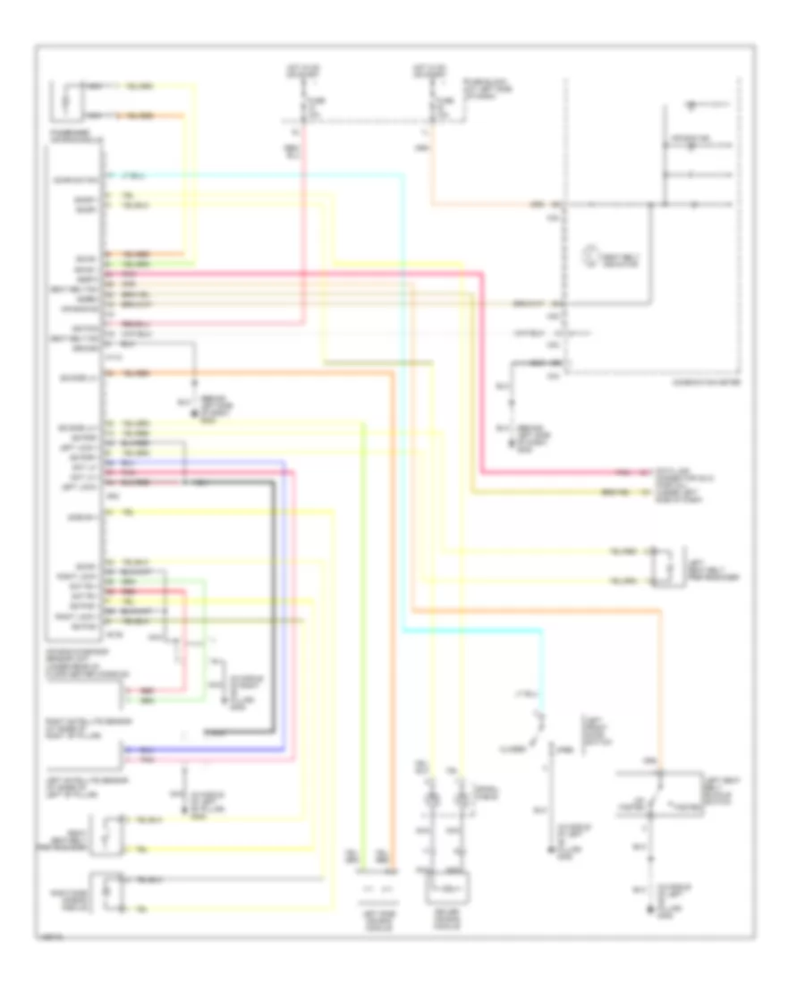
Manual A/C Wiring Diagram (1 of 2) for Nissan Maxima GLE 2000
List of elements for Manual A/C Wiring Diagram (1 of 2) for Nissan Maxima GLE 2000:
- (next to blower motor)
- +cold -hot
- +def -vent
- +fre -rec
- +hot -cold
- +rec -fre
- +vent -def
- A/c control unit (behind center of dash)
- A/c switch
- Acc
- Air mix door motor (behind center of dash)
- B/l foot
- Bl vent
- Blower motor (behind right side of dash)
- Blower motor relay (behind right side of dash)
- Def
- Defogger system
- Ecm comp
- F/cool
- F/d def
- F/hot
- Fan resistor
- Fan switch
- Foot f/d
- Fre
- Fre input
- Front def switch
- Fuse & fusible link box (at left side of eng compt)
- Fuse 19 10a
- Fuse 51 15a
- Fuse 52 15a
- Fuse block (behind left side of dash)
- G100 (front of left front fender)
- G102 (left front strut tower)
- G201 (behind right side of dash)
- G202 (left side of dash)
- Gnd
- Hot at all times
- Hot in on or start
- Ignition swiitch
- Ill
- Intake door motor (behind right side of dash)
- Interior lights system
- J/c 7 (in fuse & fusible link box)
- Light
- Lock
- M56
- M57
- Mode door motor (behind center of dash)
- Off
- Pbr
- Position switches
- Rec
- Rec input
- Red
- Rr def on
- Rr dep f/b
- Run
- Start
- Vent
- Vent b/l
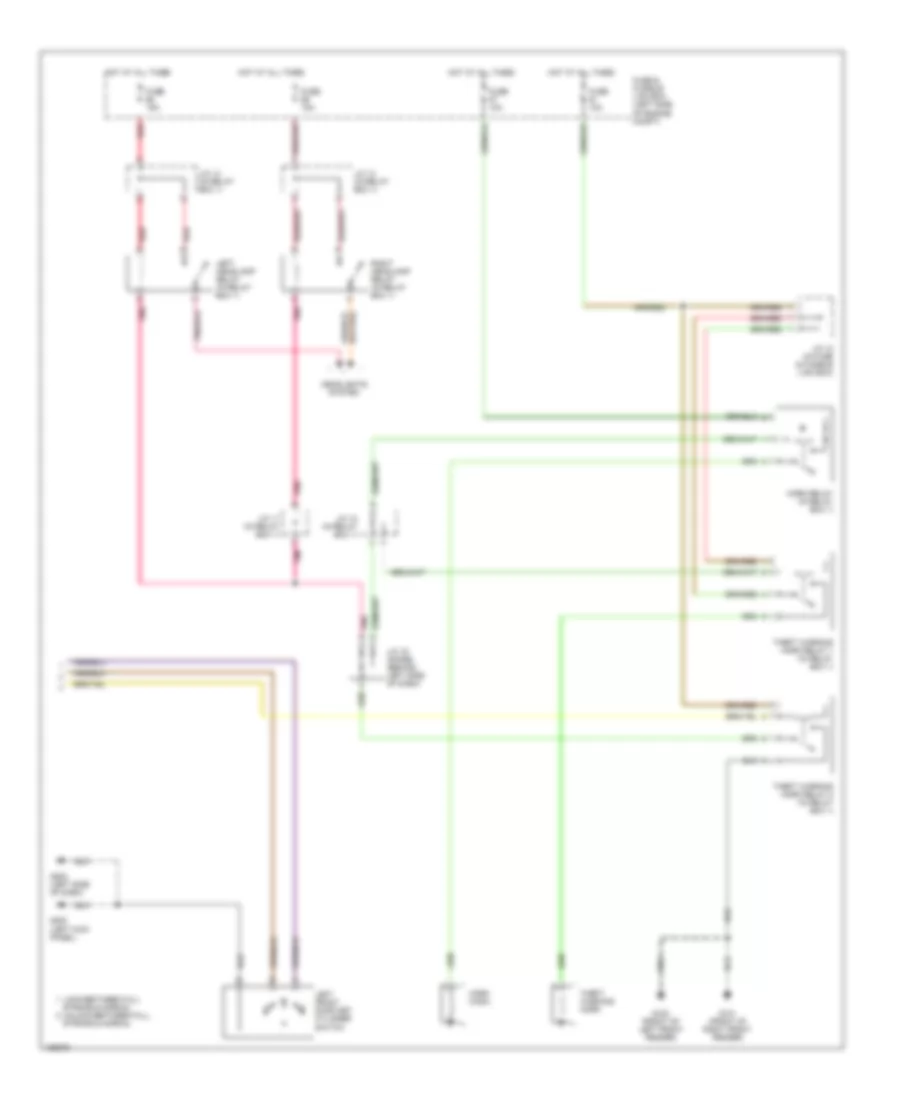
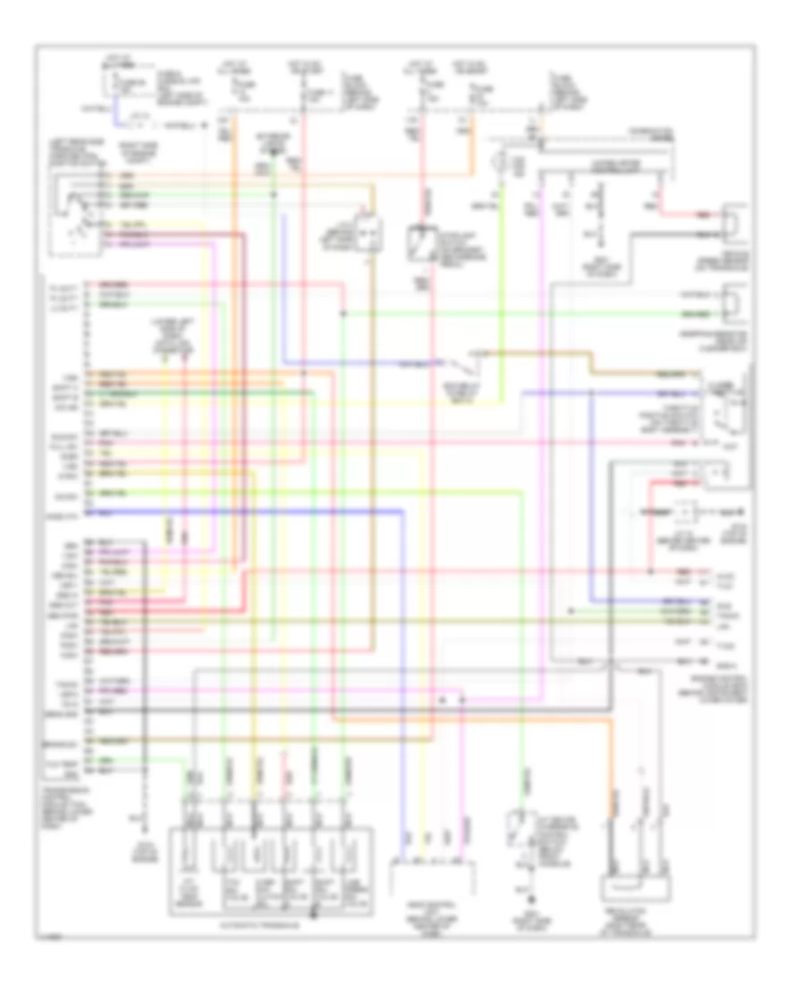
Manual A/C Wiring Diagram (2 of 2) for Nissan Maxima GLE 2000
List of elements for Manual A/C Wiring Diagram (2 of 2) for Nissan Maxima GLE 2000:
- (in fuse & fusible link box) j/c 10
- Acpdcut
- Acrly
- Air conditioner relay
- Arcon
- Avcc
- Compressor
- Cooling fan motor 1
- Cooling fan motor 2
- Cooling fan relay 1 (in relay box 2)
- Cooling fan relay 2 (in relay box 2)
- Cooling fan relay 3 (in relay box 2)
- Engine control module (ecm) (behind instrument lower cover)
- Fuse & fusible link box (at left side of eng compt)
- Fuse & fusible link box (at left side of engine compt)
- Fuse 20 15a
- Fuse 66 10a
- Fuse block (behind left side of dash)
- Fusible link g 40a
- Fusible link h 40a
- G100 (front of left front fender)
- G101 (front of right front fender)
- Gnd-a
- Hot at all times
- Hot in on & start
- J/c 8 (in fuse & fusible link box)
- J/c 9 (in fuse & fusible link box)
- Pdpres
- Red
- Refrigerant pressure sensor (on a/c liquid tank)
- Rfrh
- Rfrl
ANTI-LOCK BRAKES
Anti-lock Brake Wiring Diagrams for Nissan Maxima GLE 2000
List of elements for Anti-lock Brake Wiring Diagrams for Nissan Maxima GLE 2000:
- (behind left side of dash, behind fuse box cover)
- (in relay box 2) abs motor relay
- (in relay box 2) abs solenoid valve relay
- (left front strut tower) g102
- 1 (or 6)
- 11k
- 2 (or 4)
- Abs
- Abs diode (behind left side of dash)
- Abs sila
- Abs/tcs control actuator (left rear of engine compt)
- Abs/tcs control unit or abs control unit (behind left kick panel)
- Ascd control unit (behind lower center of dash)
- Asr st
- Bls
- Combination meter
- Data link connector (consult)
- Diag l
- Ecu gnd
- Engine control module (ecm) (behind instrument lower cover)
- Fl in
- Fl out
- Fl ss
- Fl ss gnd
- Fr in
- Fr out
- Fr ss
- Fr ss gnd
- Fuse & fusible link box (left side of engine compt)
- Fuse 2 15a
- Fuse 30 10a
- Fuse 31 10a
- Fuse block (behind left side of dash)
- Fuse d 40a
- Fuse e 40a
- G102 (left strut tower)
- G200 (left kick panel)
- Gnd1
- Gnd2
- Hot at all times
- Hot in on or start
- Interior lights system
- Lan
- Left front wheel speed sensor
- Left rear wheel speed sensor
- Pnk
- Red
- Right front wheel speed sensor
- Right rear wheel speed sensor
- Rl in
- Rl out
- Rl ss
- Rl ss gnd
- Rr in
- Rr out
- Rr ss
- Rr ss gnd
- Rxd
- Slip
- Slip sila
- Stop- light switch (on brake pedal bracket)
- Tacho
- Tcs
- Tcs off
- Tcs off sila
- Tcs on/off switch
- Tcs switch
- Transmission control module (tcm) (behind lower center console)
- Txd
ANTI-THEFT
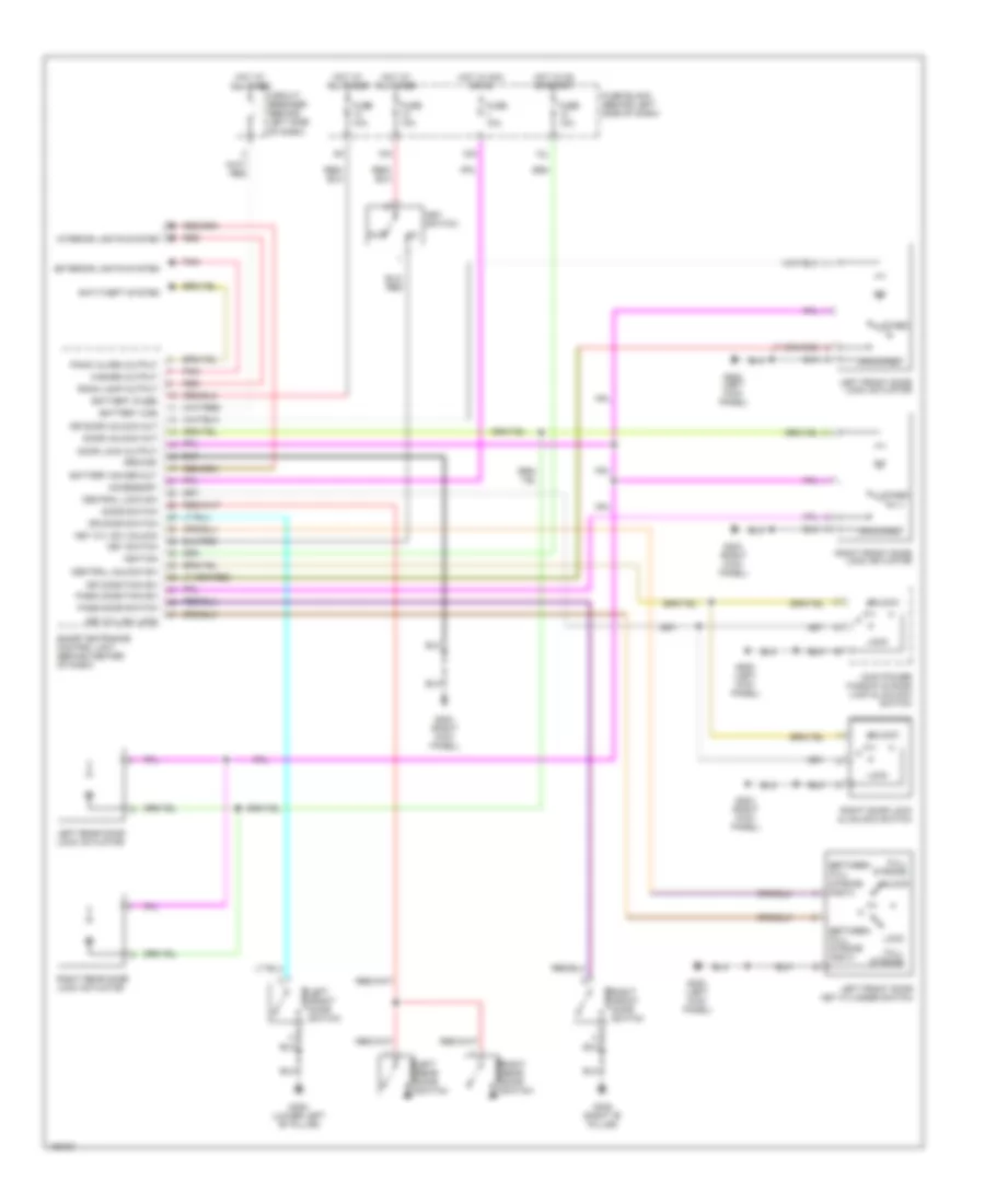
Anti-theft Wiring Diagram (1 of 2) for Nissan Maxima GLE 2000
List of elements for Anti-theft Wiring Diagram (1 of 2) for Nissan Maxima GLE 2000:
- (right "c" pillar)
- 10k
- 12k
- 12l
- Acc
- Alarm output
- Bat (fuse)
- Central lock sw
- Central unlock sw
- Clock (security indicator lamp)
- Door lock switch
- Door switch (all)
- Door switch (as)
- Dr door switch
- Fuse 10a
- Fuse block (j/b) (behind left side of dash)
- G101 (front of right front fender)
- G200 (left kick panel)
- G202 (left side of dash)
- G203 (right kick panel)
- G305 (right "b" pillar)
- G308 (lower left "b" pillar)
- G407 (center rear of trunk)
- G905
- G905 (right "c" pillar)
- Ground
- Hood switch
- Hot at all times
- Hot in acc or on
- Hot in on or start
- Ign
- Immobilizer system
- Key cyl lock sw
- Key cyl unlock sw
- Left front door lock actuator
- Left front door switch
- Left rear door switch
- Lock
- Main power window switch (left door lock switch)
- Right door lock switch
- Right front door lock actuator
- Right front door switch
- Right rear door switch
- Smart entrance control unit (behind center of dash)
- Theft indicator
- Trunk lid key cylinder switch
- Trunk key switch
- Trunk room lamp switch
- Trunk switch
- Unlock
Anti-theft Wiring Diagram (2 of 2) for Nissan Maxima GLE 2000
List of elements for Anti-theft Wiring Diagram (2 of 2) for Nissan Maxima GLE 2000:
- (left kick panel)
- Fuse & fusible link box (left side of engine compt)
- Fuse 10a
- Fuse 15a
- G100 (front of left front fender)
- G101 (front of right front fender)
- G200
- G202 (left side of dash)
- Headlights system
- Horn (high)
- Horn relay (in relay box 1)
- Hot at all times
- J/c 10 (in fuse & fusible link box)
- J/c 11 (in relay box 1)
- J/c 12 (in relay box 1)
- J/c 14 (in relay box 1)
- J/c 16 (diode) (behind left side of dash)
- Left front door key cylinder switch
- Left headlamp relay (in relay box 1)
- Lock-between full
- Pnk
- Red
- Right headlamp relay (in relay box 1)
- Stroke & normal
- Stroke & normal unlock-between full
- Theft warning horn
- Theft warning horn relay 1 (in relay box 1)
- Theft warning horn relay 2 (in relay box 1)
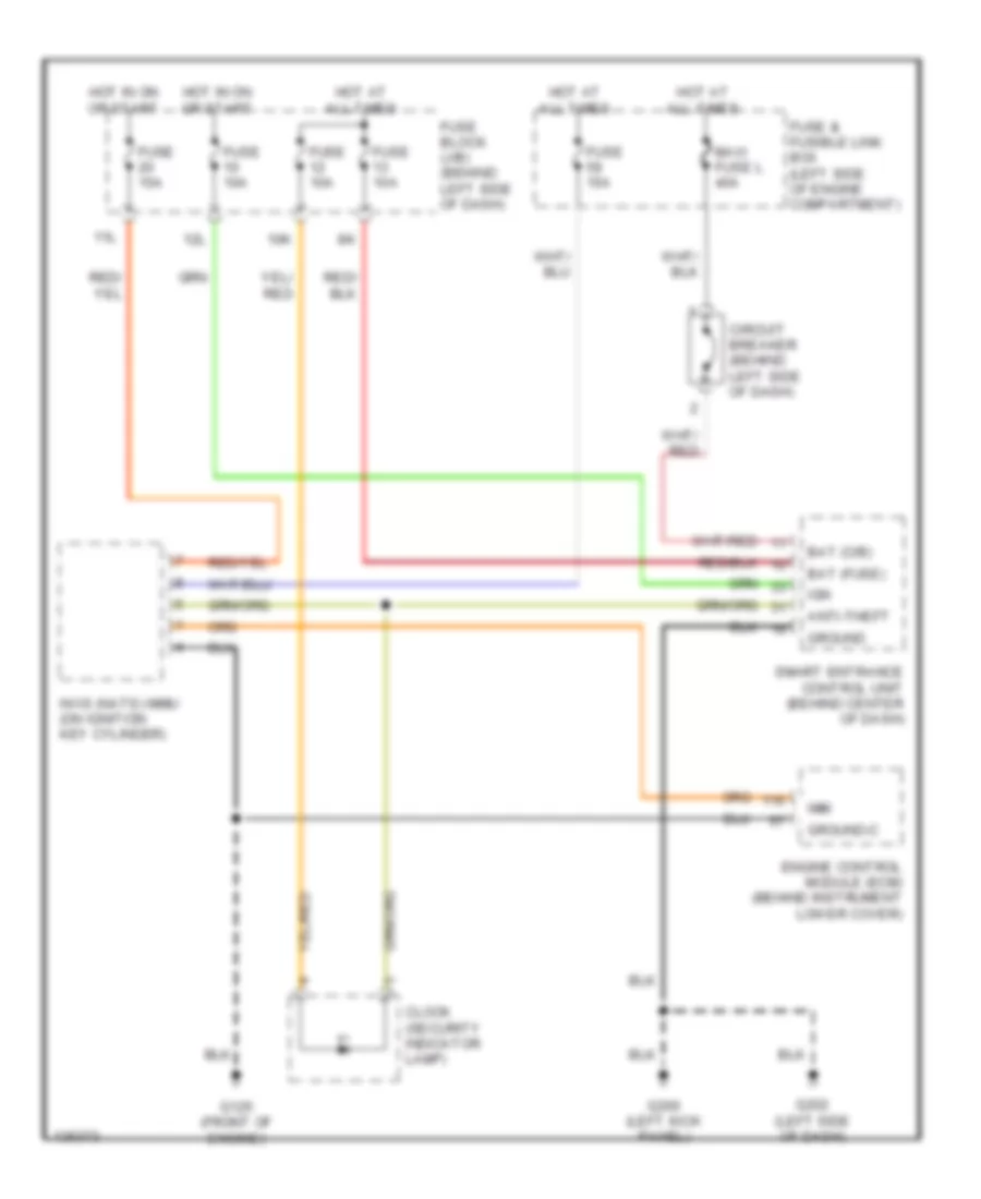
Immobilizer Wiring Diagram (NATS) for Nissan Maxima GLE 2000
List of elements for Immobilizer Wiring Diagram (NATS) for Nissan Maxima GLE 2000:
- 10k
- 11l
- 12l
- Anti-theft
- Bat (c/b)
- Bat (fuse)
- Circuit breaker (behind left side of dash)
- Clock (security indicator lamp)
- Engine control module (ecm) (behind instrument lower cover)
- Fuse & fusible link box (left side of engine compartment)
- Fuse 10a
- Fuse 15a
- Fuse block (j/b) (behind left side of dash)
- G125 (front of engine)
- G200 (left kick panel)
- G202 (left side of dash)
- Ground
- Ground-c
- Hot at all times
- Hot in on or start
- Ign
- Imm
- Maxi fuse l 40a
- Nvis (nats) immu (on ignition key cylinder)
- Smart entrance control unit (behind center of dash)
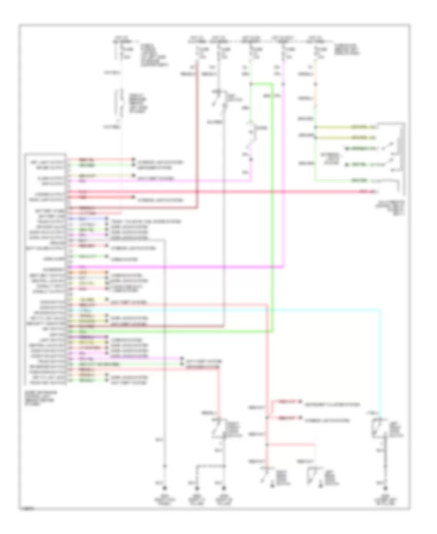
BODY COMPUTER
Body Computer Wiring Diagrams for Nissan Maxima GLE 2000
List of elements for Body Computer Wiring Diagrams for Nissan Maxima GLE 2000:
- 10h
- 12k
- 12l
- Accessory
- Alarm output
- Anti-theft system
- Batt saver output
- Battery (c/b)
- Battery (fuse)
- Central lock sw
- Central unlck sw
- Circuit breaker (behind left side of dash)
- Computer data lines system
- Condition switch
- Consult input
- Consult output
- Defogger system
- Diode
- Door lock output
- Door locks system
- Door switch
- Door unlk output
- Dr door switch
- Dr door unlck
- Exterior lights system
- Fuse & fusible link box (at left side of engine compartment)
- Fuse 10a
- Fuse block (behind left side of dash)
- Fuse i 40a
- G203 (right kick panel)
- G305 (right "b" pillar)
- G308 (lower left "b" pillar)
- G905 (right "c" pillar)
- Ground
- Hazard output
- Hood switch
- Horn chirp
- Horns system
- Hot at all times
- Hot in accy or on
- Hot in on or start
- Ignition
- Instrument cluster system
- Interior lights system
- Key cyl sw lock
- Key cyl sw unlck
- Key light output
- Key switch
- Left front door switch
- Left rear door switch
- Light switch
- Multi-remote control relay (in relay box 1)
- Pass door switch
- Pnk
- Rap output
- Red
- Right front door switch
- Right rear door switch
- Room lamp output
- Rr def output
- Rr defggr switch
- Seat belt switch
- Security indicator
- Smart entrance control unit (behind center of dash)
- Trunk key switch
- Trunk output
- Trunk switch
- Trunk, tailgate, fuel doors system
- Warning system
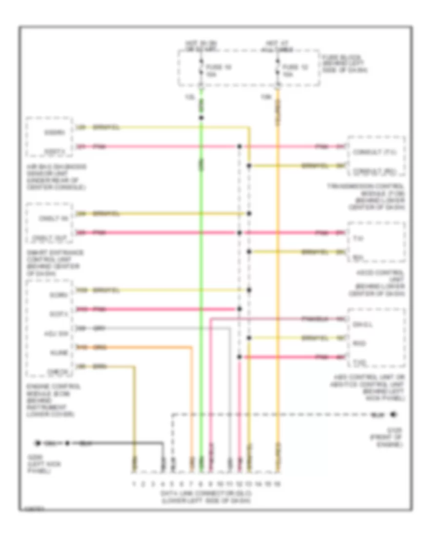
COMPUTER DATA LINES
Computer Data Lines for Nissan Maxima GLE 2000
List of elements for Computer Data Lines for Nissan Maxima GLE 2000:
- Abs control unit or abs/tcs control unit (behind left kick panel)
- Adj sw
- Air bag diagnosis sensor unit (under rear of center console)
- Ascd control unit (behind lower center of dash)
- Check
- Cnslt in
- Cnslt out
- Consult (rx)
- Consult (tx)
- Data link connector (dlc) (lower left side of dash)
- Diag l
- Engine control module (ecm) (behind instrument lower cover)
- Fuse 10 10a
- Fuse 12 10a
- Fuse block (behind left side of dash)
- G125 (front of engine)
- G200 (left kick panel)
- Hot at all times
- Hot in on or start
- Kline
- Pnk
- Rxd
- Rxi
- Scirx
- Scitx
- Smart entrance control unit (behind center of dash)
- Sssrx
- Ssstx
- Transmission control module (tcm) (behind lower center of dash)
- Txd
- Txi
COOLING FAN
Cooling Fan Wiring Diagram for Nissan Maxima GLE 2000
List of elements for Cooling Fan Wiring Diagram for Nissan Maxima GLE 2000:
- (in fuse & fusible link box) j/c 10
- Avcc
- Cooling fan motor 1
- Cooling fan motor 2
- Cooling fan relay 1 (in relay box 2)
- Cooling fan relay 2 (in relay box 2)
- Cooling fan relay 3 (in relay box 2)
- Engine control module (ecm) (behind instrument lower cover)
- Fuse & fusible link box (at left side of engine compt)
- Fuse 20 15a
- Fuse block (behind left side of dash)
- Fusible link g 40a
- Fusible link h 40a
- G100 (front of left front fender)
- G101 (front of right front fender)
- Gnd-a
- Hot at all times
- Hot in on & start
- J/c 8 (in fuse & fusible link box)
- J/c 9 (in fuse & fusible link box)
- Pdpres
- Red
- Refrigerant pressure sensor (on a/c liquid tank)
- Rfrh
- Rfrl
- Transmissions system
CRUISE CONTROL
Cruise Control Wiring Diagram for Nissan Maxima GLE 2000
List of elements for Cruise Control Wiring Diagram for Nissan Maxima GLE 2000:
- 11k
- Abs/tcs control unit (behind left kick panel)
- Actr out high
- Air valve
- Air valve out
- Ascd 4th cut sw
- Ascd brake switch (on brake pedal bracket)
- Ascd clutch switch (on clutch pedal bracket)
- Ascd control unit (behind lower center of dash)
- Ascd cruise sw
- Ascd pump (left side of engine compt, behind strut tower)
- Ascd steering switch
- Asr st
- Brake nc sw
- Brake no sw
- Cancel switch
- Combination meter
- Cruise
- Cruise lamp
- Cruise signal
- Data link connector (lower left
- Engine control module (ecm) (behind instrument lower cover)
- Fuse & fusible link block (at left side of engine compt)
- Fuse 10 10a
- Fuse 2 15a
- Fuse 20 15a
- Fuse 30 10a
- Fuse 57 10a
- Fuse block (behind left side of dash)
- G125 (front of engine)
- G200 (left kick panel)
- G202 (left side of dash)
- Ground
- Ground-a
- Ground-c
- Horn relay (in relay box 1)
- Horn sw
- Horn system
- Hot at all times
- Hot in on or start
- Ignition switch
- J/c 12 (in relay box 1)
- J/c 8 (in fuse & fusible link box)
- Main switch
- Nca
- Od cancel
- Park/neutral position relay (in relay box 2)
- Park/neutral position switch (on left rear side of transaxle)
- Pnk
- Red
- Release valve
- Res/acc sw
- Resume/ accel switch
- Rxi
- Scirx
- Scitx
- Sensor ground
- Set
- Set lamp out
- Set/coast sw
- Set/coast switch
- Shift solenoid a
- Shift solenoid valve a
- Side of dash)
- Solenoid input
- Speed sensor
- Spiral cable
- Starting/ charging system
- Stoplight switch (on brake pedal bracket)
- Tcs
- Throttle pos
- Transmission control module (tcm) (w/a/t) (behind lower center of dash)
- Tvo0
- Tvo1
- Txi
- Vacuum motor
- Vehicle speed
- Vehicle speed sensor
- W/a/t
- W/m/t
DEFOGGERS
Defogger Wiring Diagram for Nissan Maxima GLE 2000
List of elements for Defogger Wiring Diagram for Nissan Maxima GLE 2000:
- 12l
- A/c auto amplifier (or a/c control unit) (behind center of dash)
- Bat (fuse)
- Condenser (at left "c" pillar)
- Door mirror defogger relay (right side of engine compartment, in relay box 1)
- Engine controls system
- Fuse 10a
- Fuse 20a
- Fuse 20a
- Fuse block (behind left side of dash)
- G101 (front of right front fender)
- G200 (left kick panel)
- G202 (left side of dash)
- G203 (right kick panel)
- G905 (right "c" pillar)
- Ground
- Hot at all times
- Hot in on or start
- Ign
- Left door mirror defogger (door mirror actuator)
- M40
- M41
- Nca
- Rear window defogger
- Rear window defogger relay (behind left kick panel)
- Rear window defogger switch
- Right door mirror defogger (door mirror actuator)
- Rr def f/b
- Rr def out
- Rr def sw
- Smart entrance control unit (behind center of dash)
- W/ auto a/c
- W/o auto a/c
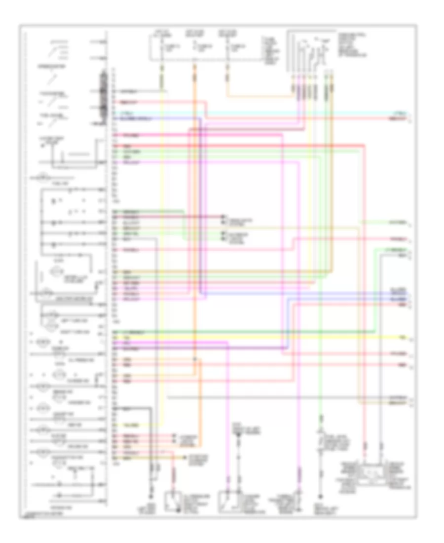
ENGINE PERFORMANCE
3.0L
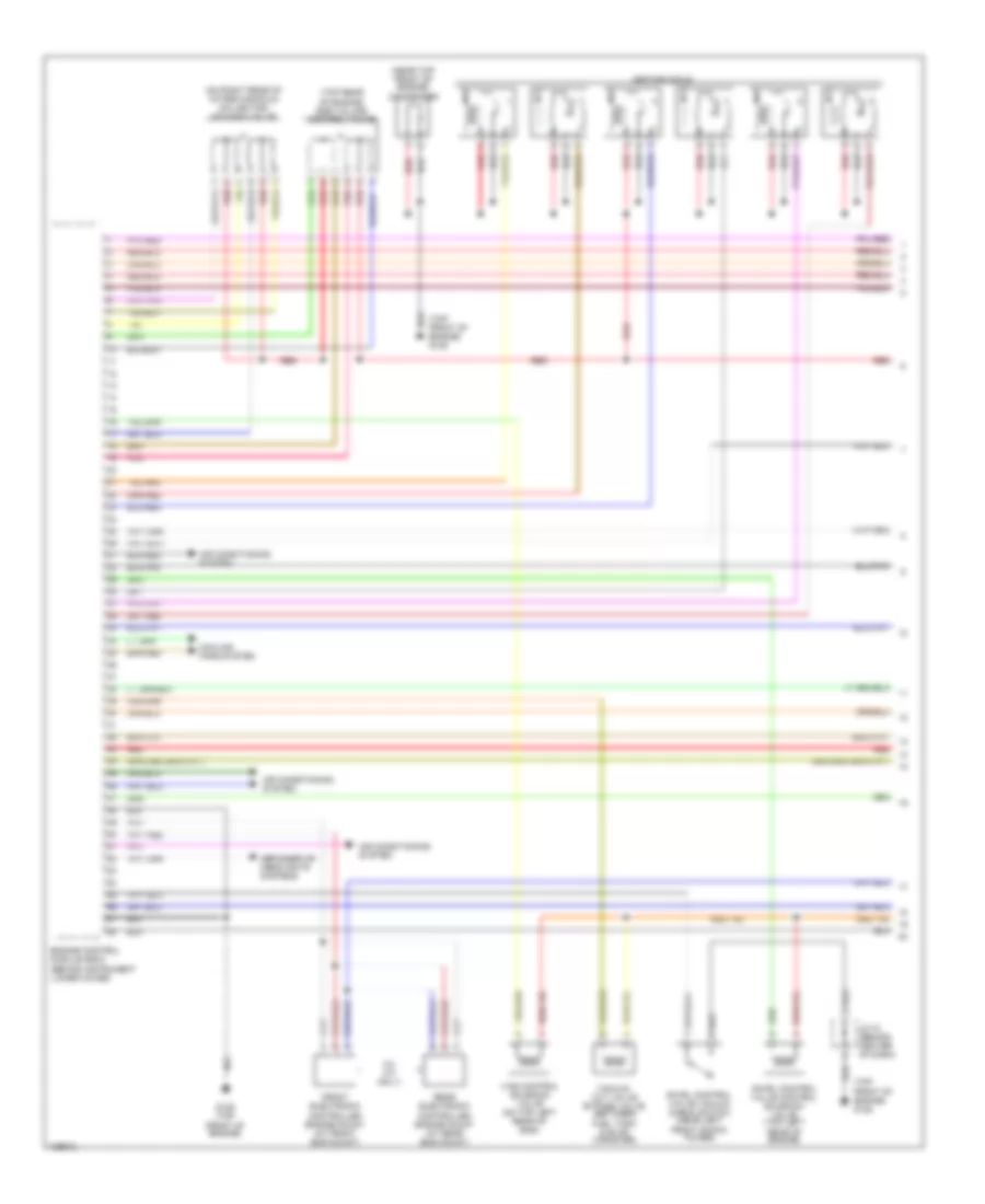
3.0L, Engine Performance Wiring Diagrams (1 of 4) for Nissan Maxima GLE 2000
List of elements for 3.0L, Engine Performance Wiring Diagrams (1 of 4) for Nissan Maxima GLE 2000:
- (near top front of engine) condenser
- (on right rear of intake manifold collector) iacv-aac valve
- (top front of engine) g125
- (top rear of engine) egr volume control valve
- (w/ a/t only)
- Air conditioning system
- Cooling fans system
- Defogger or headlights systems
- Engine control module (ecm) (behind instrument lower cover)
- Front electronic controlled engine mount (at front eng mount)
- G125 (top front of engine)
- Ignition coils
- Jc-18 (behind center of dash)
- Pnk
- Rear electronic controlled engine mount (at rear eng mount)
- Red
- Swirl control valve control solenoid valve (top left rear of engine)
- Swirl control valve vacuum check switch (near left front shock tower)
- Vacuum cut valve bypass valve (between fuel tank & evap canister)
- Vias control solenoid valve (on top left rear of eng)
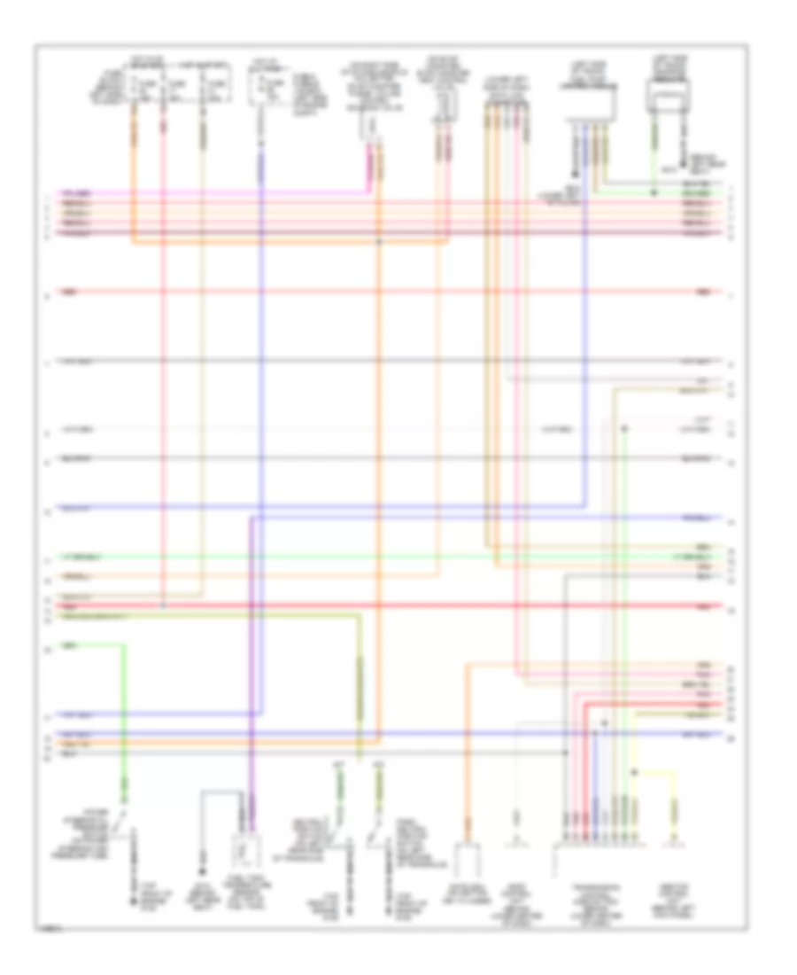
3.0L, Engine Performance Wiring Diagrams (2 of 4) for Nissan Maxima GLE 2000
List of elements for 3.0L, Engine Performance Wiring Diagrams (2 of 4) for Nissan Maxima GLE 2000:
- (behind left rear seat)
- (left side of trunk) dropping resistor
- (left side of trunk) fuel pump control module
- (lower left side of dash) data link connector
- (on evap canister) evap canister vent control valve
- (on right side of intake manifold collector) evap canister purge volume control solenoid valve
- (top front of engine) g125
- 11l
- A/t
- Abs/tcs control unit (behind left kick panel)
- Ascd control unit (behind lower center of dash)
- Fuel tank temperature sensor (on top of fuel tank)
- Fuse & fusible link box (left side of engine compt)
- Fuse 10a
- Fuse 15a
- Fuse block (behind left side of dash)
- G308 (lower left "b" pillar)
- G312
- G312 (behind left rear seat)
- Hot at all times
- Hot in on or start
- Hot in start
- M/t
- Nats immu (on ignition key cylinder)
- Neutral position switch (on left rear side of transaxle)
- Park/ neutral position switch (on left rear side of transaxle)
- Pnk
- Power steering oil pressure switch (on power steering high pressure tube)
- Red
- Transmission control module (tcm) (behind lower center of dash)
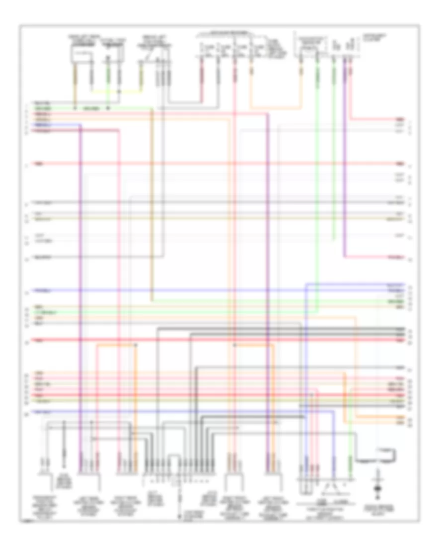
3.0L, Engine Performance Wiring Diagrams (3 of 4) for Nissan Maxima GLE 2000
List of elements for 3.0L, Engine Performance Wiring Diagrams (3 of 4) for Nissan Maxima GLE 2000:
- (behind left kick panel) fuel pump relay
- (in fuel tank) fuel pump
- (near left rear wheelwell) condenser
- (top front of engine) g125
- 13l
- Closed
- Crankshaft position sensor (ref) (below crankshaft pulley)
- Fuse 10a
- Fuse 15a
- Fuse block (behind left side of dash)
- G125 (behind center of dash)
- Heated oxygen sensor (in exhaust system)
- Hot in on or start
- Instrument cluster
- Jc-17 (behind center of dash)
- Jc-18 (behind center of dash)
- Knock sensor (top of cyliner block)
- Left front heated oxygen sensor (on front exhaust tube assembly)
- Left rear heated oxygen sensor (in exhaust system)
- Malfunction indicator
- Nca
- Pnk
- Red
- Right front heated oxygen sensor (on front exhaust tube assembly)
- Right rear
- Tach sig
- Throttle position sensor (on throttle body)
- Vsp
- Vss in
- Wide open
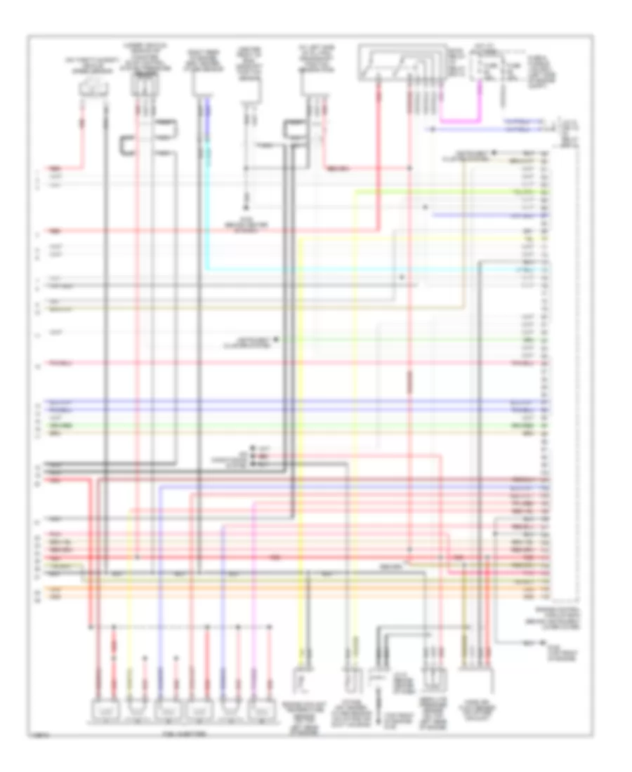
3.0L, Engine Performance Wiring Diagrams (4 of 4) for Nissan Maxima GLE 2000
List of elements for 3.0L, Engine Performance Wiring Diagrams (4 of 4) for Nissan Maxima GLE 2000:
- (at left side of oil pan) crankshaft position sensor (pos)
- (center front of eng) camshaft position sensor
- (on throttle body) vehicle speed sensor
- (right rear of engine) egr temper- ature sensor
- (top front of engine) g125
- (under vehicle, near evap canister) evap control system pressure sensor
- Absolute pressure sensor (on top left rear of engine)
- Air conditioning system
- Eccs relay (in relay box 2)
- Engine control module (ecm) (behind instrument lower cover)
- Engine coolant temperature sensor (on top left rear of engine)
- Fuel injectors
- Fuse & fusible link box (left side of engine compt)
- Fuse 15a
- G125 (behind center of dash)
- G125 (top front of engine)
- Hot at all times
- Instrument cluster system
- Intake air temper- ature sensor (on intake air duct housing)
- J/c-12 (or 13) (in relay box 1)
- Jc-18 (behind center of dash)
- Mass air- flow sensor (on intake air duct)
- Nca
- Pnk
- Red
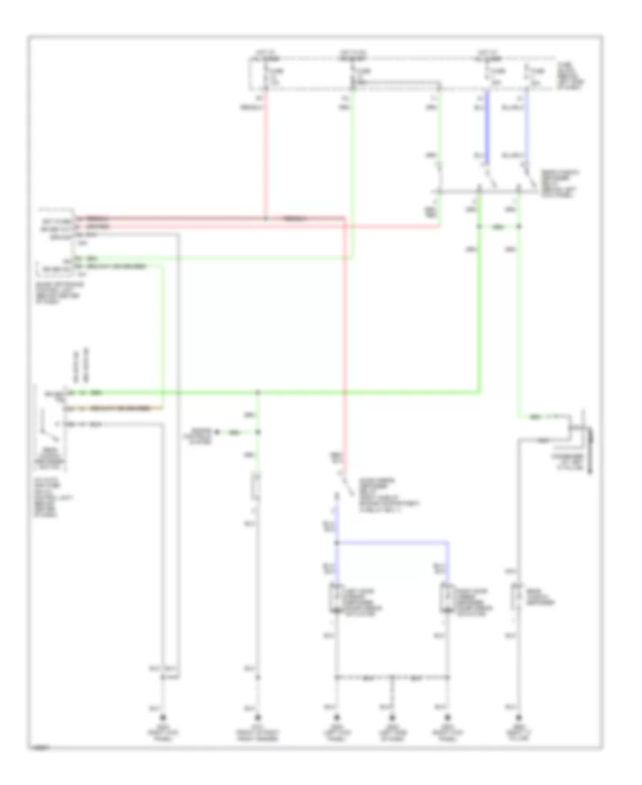
EXTERIOR LIGHTS
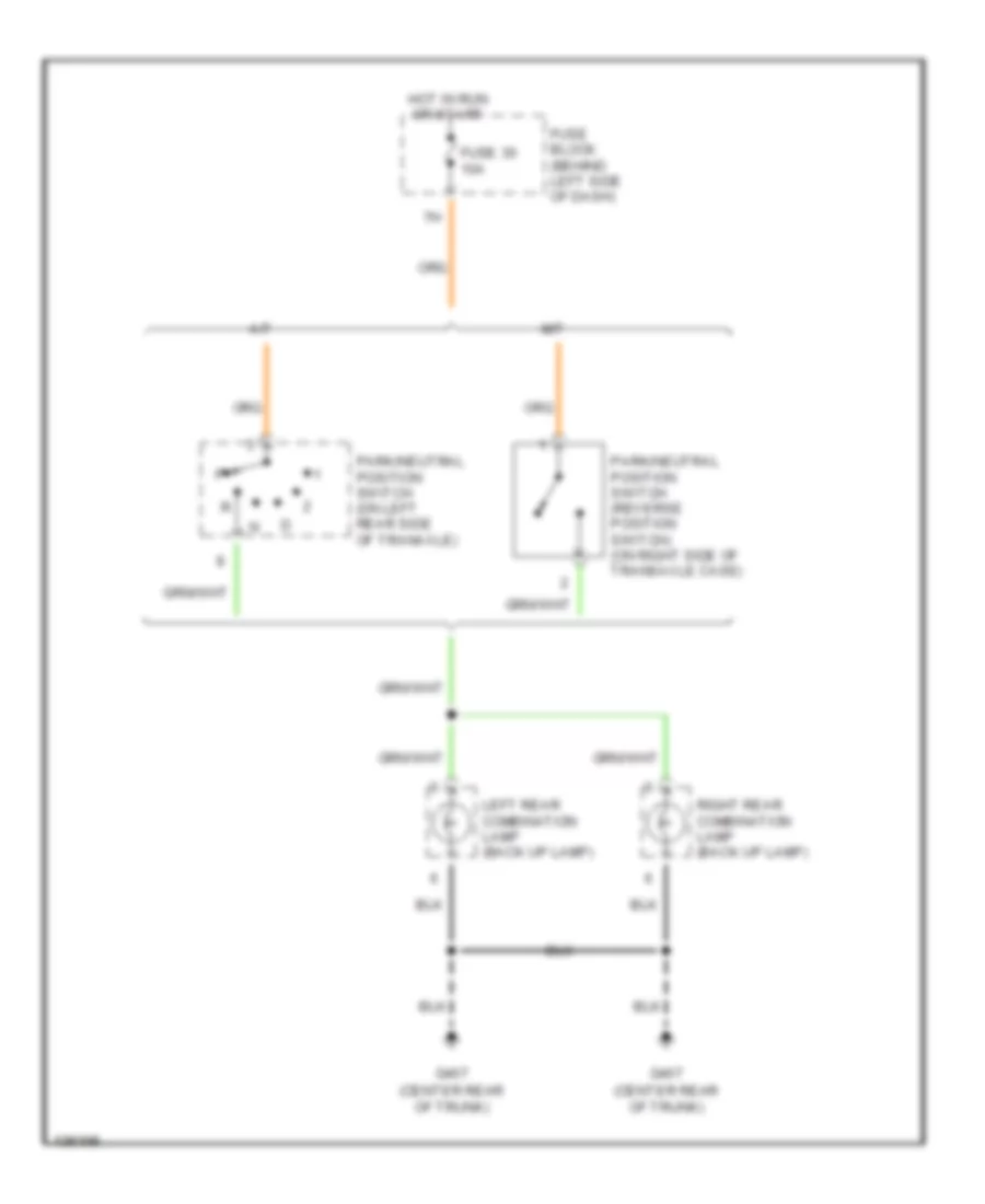
Back-up Lamps Wiring Diagram for Nissan Maxima GLE 2000
List of elements for Back-up Lamps Wiring Diagram for Nissan Maxima GLE 2000:
- (center rear of trunk)
- A/t
- Fuse 30 10a
- Fuse block (behind left side of dash)
- G407
- Hot in run or start
- Left rear combination lamp (back up lamp)
- M/t
- Park/neutral position switch (on left rear side of tranaxle)
- Park/neutral position switch (reverse position switch) (on right side of transaxle case)
- Right rear combination lamp (back up lamp)
Exterior Lamps Wiring Diagram (1 of 2) for Nissan Maxima GLE 2000
List of elements for Exterior Lamps Wiring Diagram (1 of 2) for Nissan Maxima GLE 2000:
- 11k
- 1st
- 2nd
- Auto
- Auto light control unit (behind left side of dash)
- E100
- E97
- Fuse & fusible link box (left side of engine compartment)
- Fuse 10a
- Fuse 15a
- Fuse block (behind left side of dash)
- G100 (front of left front fender)
- G101 (front of right front fender)
- G305 (right "b" pillar)
- G308 (left "b" pillar)
- G904 (left "c" pillar)
- G905 (right "c" pillar)
- Headlamp battery saver control unit (behind left side of dash)
- High mounted stop light
- Hot at all times
- J/c 13 (in relay box 1)
- J/c 7 (in fuse & fusible link box)
- Left front side marker lamp
- Left license lamp
- Left park- ing lamp
- Lighting switch
- M26
- M27
- Off
- Right front side marker lamp
- Right license lamp
- Right park- ing lamp
- Stoplight switch (on brake pedal bracket)
- Tail lamp relay
- Tail lamp relay (in relay box 1)
- Tail lamp rly
- Tail lamp sw1
- Tail lamp sw2
- W/ spoiler
- W/o spoiler
Exterior Lamps Wiring Diagram (2 of 2) for Nissan Maxima GLE 2000
List of elements for Exterior Lamps Wiring Diagram (2 of 2) for Nissan Maxima GLE 2000:
- (in relay box 1)
- Combination flasher unit (behind left side of dash)
- Combination meter
- Fuse 10a
- Fuse block (behind left side of dash)
- G100 (front of left front fender)
- G101 (front of right front fender)
- G202 (left side of dash)
- G203 (right kick panel)
- G407 (center rear of trunk)
- Hazard output
- Hazard switch
- Hot at all times
- Hot in on or start
- Illumination
- Interior lights system
- Left front turn signal lamp
- Left rear combination lamp
- Left rear side marker lamp
- Left turn ind
- Multi remote control relay
- Pnk
- Right front turn signal lamp
- Right rear combination lamp
- Right rear side marker lamp
- Right turn ind
- Smart entrance control unit (behind center of dash)
- Stop
- Tail
- Turn
- Turn signal switch
GROUND DISTRIBUTION
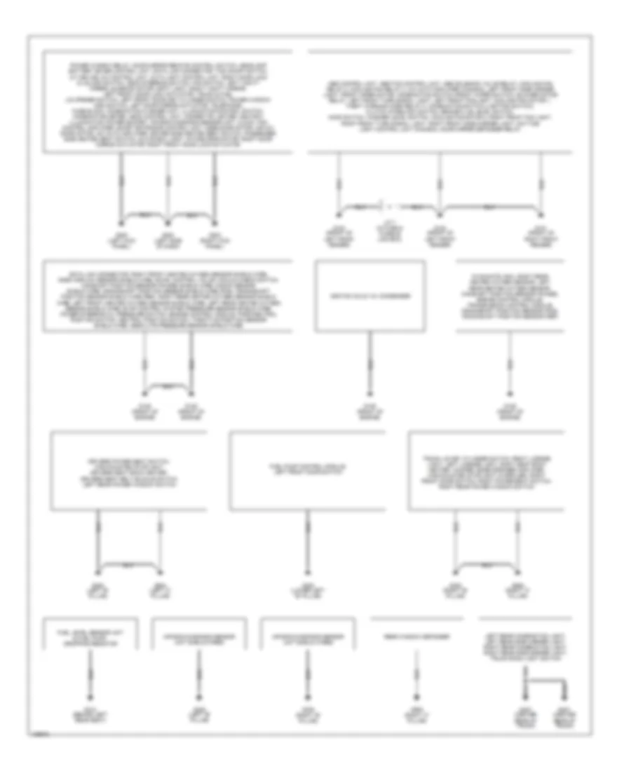
Ground Distribution Wiring Diagram for Nissan Maxima GLE 2000
List of elements for Ground Distribution Wiring Diagram for Nissan Maxima GLE 2000:
- Abs control unit, abs/tcs control unit, abs solenoid valve relay, cooling fan relay 2, cooling fan relay 3, a/c auto amplifier (canada), left front side marker light, front wiper motor, combination switch (front wiper switch), blower motor relay, left front turn signal light, left front fog light, cooling fan motor 1, theft warning horn relay 2, combination switch (lighting switch), clutch interlock switch, brake fliud level switch, hood switch, washer level switch, cooling fan motor 2, right front fog light, right front turn signal light, right front side marker light, daytime light control unit (canada), door mirror defogger relay
- Air bag diagnosis sensor unit sheild wires
- Data link connector, right front heated oxygen sensor shield wire, mass airflow sensor shield wire, swirl control valve vacuum check switch, camshaft position sensor (phase) shield wire, knock sensor shield wire, crankshaft position sensor shield wire (pos), crankshaft position sensor shield wire (ref), right rear heated oxygen sensor shield wire, left front heated oxygen sensor shield wire, left rear heated oxygen sensor shield wire, evap control system pressure sensor shield wire, power steering oil pressure switch, engine control module, park/neutral position switch, neutral position switch, throttle position sensor shield wire, absolute pressure sensor shield wire
- Drivers power seat switch, high-mounted stoplight, drivers seat back heater, drivers seat belt buckle switch, left rear power window switch
- Fuel level sensor unit & fuel pump, dropping resistor
- Fuel pump control module, left front door switch
- G100 (front of left front fender)
- G101 (front of right front fender)
- G125 (front of engine)
- G200 (left kick panel)
- G202 (left side of dash)
- G203 (right kick panel)
- G305 (right "b" pillar)
- G308 (left "b" pillar)
- G308 (lower left "b" pillar)
- G312 (behind left rear seat)
- G407 (center rear of trunk)
- G904 (left "c" pillar)
- G905 (right "c" pillar)
- Ignition coils 1-6, condenser
- J/c 7 (in fuse & fusible link box)
- Left rear combination light, left rear side marker light, right rear combination light, right rear side marker light, trunk room light switch
- Nvis (nats) immu, right rear heated oxygen sensor, left rear heated oxygen sensor, camshaft position sensor (phase), engine control module, transmission control module, crankshaft position sensor (pos), crankshaft position sensor (ref)
- Power window relay, door mirror remote control switch, headlamp battery saver control unit, data link connector, tcs on/off switch, a/t device, a/c control unit, auto light control unit, right door lock & unlock switch, ascd steering switch, fan switch, left vanity mirror, sunroof motor, spot light, right vanity mirror, left front door lock actuator, trunk & fuel lid opener switch, left front door key cylinder switch, power window main switch, left door mirror actuator, telephone, fuse block, combination flasher unit, illumination control switch, combination meter, ascd control unit, cigarette lighter, ashtray illumination, power socket, air bag diagnosis sensor unit, clock, fan control amplifier, smart entrance control unit, mode door motor, air mix door motor, a/c auto amplifier, driver side heated seat switch, passenger side heated seat switch, glove box light, intake door motor, right door mirror actuator, right front door lock actuator
- Rear window defogger
- Trunk lid key cylinder switch, right license light, left license light, right seat back heater, woofer, bose speaker amplifier, high-mounted stoplight (w/spoiler), right front door switch, right power seat switch, right rear power window switch
HEADLIGHTS
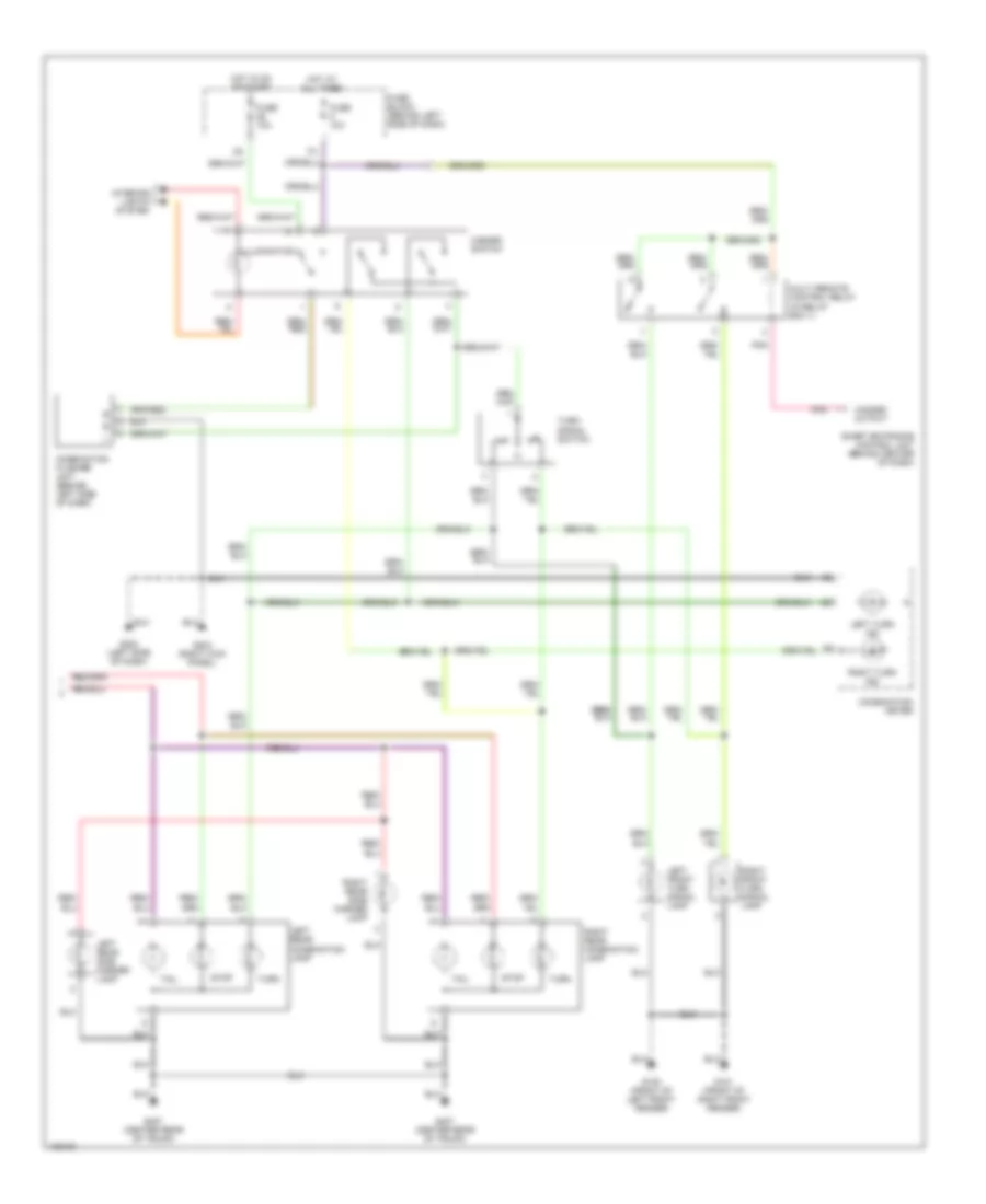
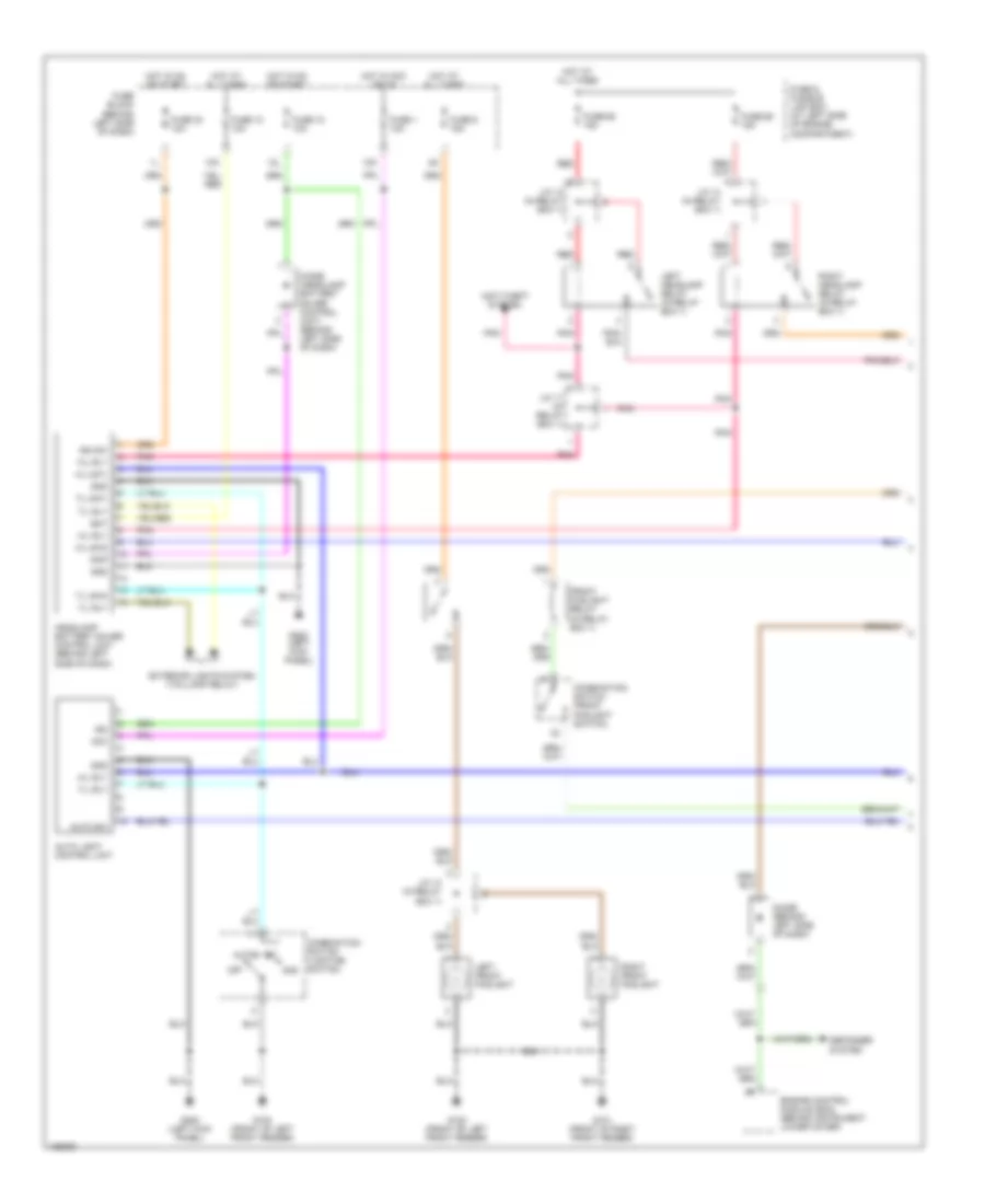
Headlight Wiring Diagram, with DRL (1 of 2) for Nissan Maxima GLE 2000
List of elements for Headlight Wiring Diagram, with DRL (1 of 2) for Nissan Maxima GLE 2000:
- (behind left side of dash)
- 10k
- 12k
- 12l
- 1st
- 2nd
- Acc
- Anti-theft system
- Auto
- Auto light control unit
- Auto sw
- Bat
- Combination switch (front foglight switch)
- Combination switch (lighting switch)
- Defogger system
- Diode (behind left side of dash)
- Diode (headlamp battery saver control unit) (behind left side of dash)
- Engine control module (ecm) (behind instrument lower cover)
- Exterior lights system (taillamp relay)
- Front foglight relay (in relay box 1)
- Fuse & fusible link box (at left side of engine compartment)
- Fuse 1 10a
- Fuse 10 10a
- Fuse 12 10a
- Fuse 30 10a
- Fuse 6 15a
- Fuse 68 15a
- Fuse 69 15a
- Fuse block
- G100 (front of left front fender)
- G101 (front of right front fender)
- G200 (left kick panel)
- Gnd
- H/l rly
- H/l sw1
- H/l sw2
- Headlamp battery saver control unit (behind left side of dash)
- Hot at all times
- Hot in acc or on
- Hot in on or start
- Ign
- Ign sw
- J/c 11 (in relay box 1)
- J/c 13 (in relay box 1)
- J/c 14 (in relay box 1)
- Left front foglight
- Left headlamp relay (in relay box 1)
- Off
- Pnk
- Rap
- Red
- Right front foglight
- Right headlamp relay (in relay box 1)
- T/l rly
- T/l sw1
- T/l sw2
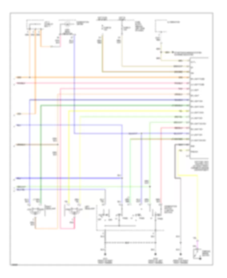
Headlight Wiring Diagram, with DRL (2 of 2) for Nissan Maxima GLE 2000
List of elements for Headlight Wiring Diagram, with DRL (2 of 2) for Nissan Maxima GLE 2000:
- (behind left side of dash)
- 1st
- 2nd
- Alt-l
- Alternator
- Auto
- Combination meter
- Combination switch (lighting switch)
- Daytime light control unit (at right front corner of engine compartment)
- Fuse 21 10a
- Fuse 28 10a
- Fuse block
- G100 (front of left front fender)
- G101 (front of right front fender)
- Gnd
- High
- High beam indicator
- Hot in on or start
- Hot in start
- Ign
- J/c 11 (in relay box 1)
- Left headlamp
- Lh light
- Lh light dim
- Lh light dim sw
- Lh light fuse
- Lh light main
- Lh light sw
- Low
- Off
- Parking brake switch
- Pass
- Pkb sw
- Pnk
- Rh light
- Rh light dim
- Rh light dim sw
- Rh light fuse
- Rh light main
- Rh light sw
- Right headlamp
- Starting/charging system (charge indicator)
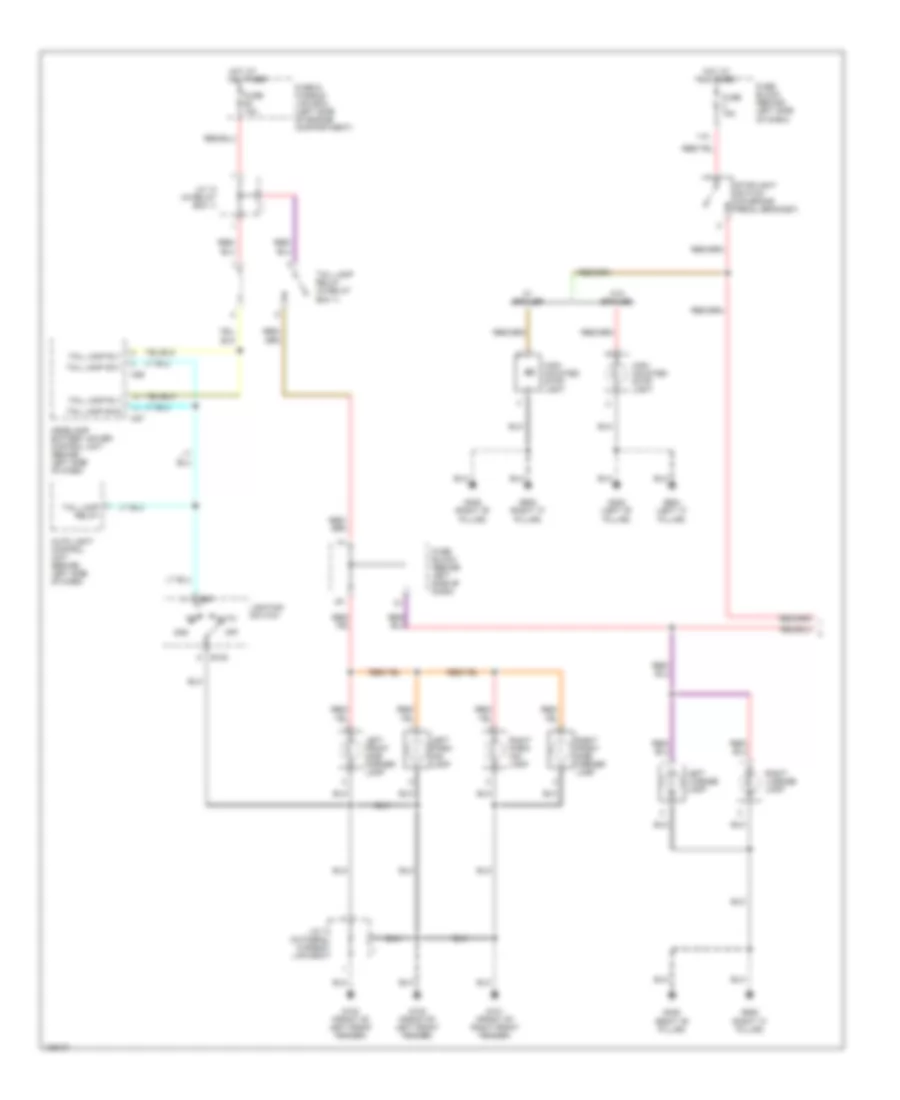
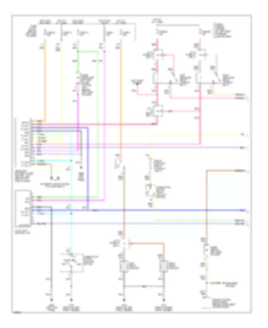
Headlight Wiring Diagram, without DRL (1 of 2) for Nissan Maxima GLE 2000
List of elements for Headlight Wiring Diagram, without DRL (1 of 2) for Nissan Maxima GLE 2000:
- (behind left side of dash)
- 10k
- 12k
- 12l
- 1st
- 2nd
- Acc
- Anti-theft system
- Auto
- Auto light control unit
- Auto sw
- Bat
- Combination switch (front foglight switch)
- Combination switch (lighting switch)
- Defogger system
- Diode (behind left side of dash)
- Diode (headlamp battery saver control unit) (behind left side of dash)
- Engine control module (ecm) (behind instrument lower cover)
- Exterior lights system (taillamp relay)
- Front foglight relay (in relay box 1)
- Fuse & fusible link box (at left side of engine compartment)
- Fuse 1 10a
- Fuse 10 10a
- Fuse 12 10a
- Fuse 30 10a
- Fuse 6 15a
- Fuse 68 15a
- Fuse 69 15a
- Fuse block
- G100 (front of left front fender)
- G101 (front of right front fender)
- G200 (left kick panel)
- Gnd
- H/l rly
- H/l sw1
- H/l sw2
- Headlamp battery saver control unit (behind left side of dash)
- Hot at all times
- Hot in acc or on
- Hot in on or start
- Ign
- Ign sw
- J/c 11 (in relay box 1)
- J/c 13 (in relay box 1)
- J/c 14 (in relay box 1)
- Left front foglight
- Left headlamp relay (in relay box 1)
- Off
- Pnk
- Rap
- Red
- Right front foglight
- Right headlamp relay (in relay box 1)
- T/l rly
- T/l sw1
- T/l sw2
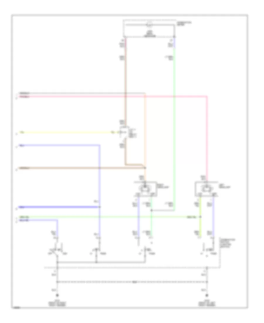
Headlight Wiring Diagram, without DRL (2 of 2) for Nissan Maxima GLE 2000
List of elements for Headlight Wiring Diagram, without DRL (2 of 2) for Nissan Maxima GLE 2000:
- 1st
- 2nd
- Auto
- Combination meter
- Combination switch (lighting switch)
- G100 (front of left front fender)
- G101 (front of right front fender)
- High
- High beam indicator
- J/c 11 (in relay box 1)
- Left headlamp
- Low
- Off
- Pass
- Right headlamp
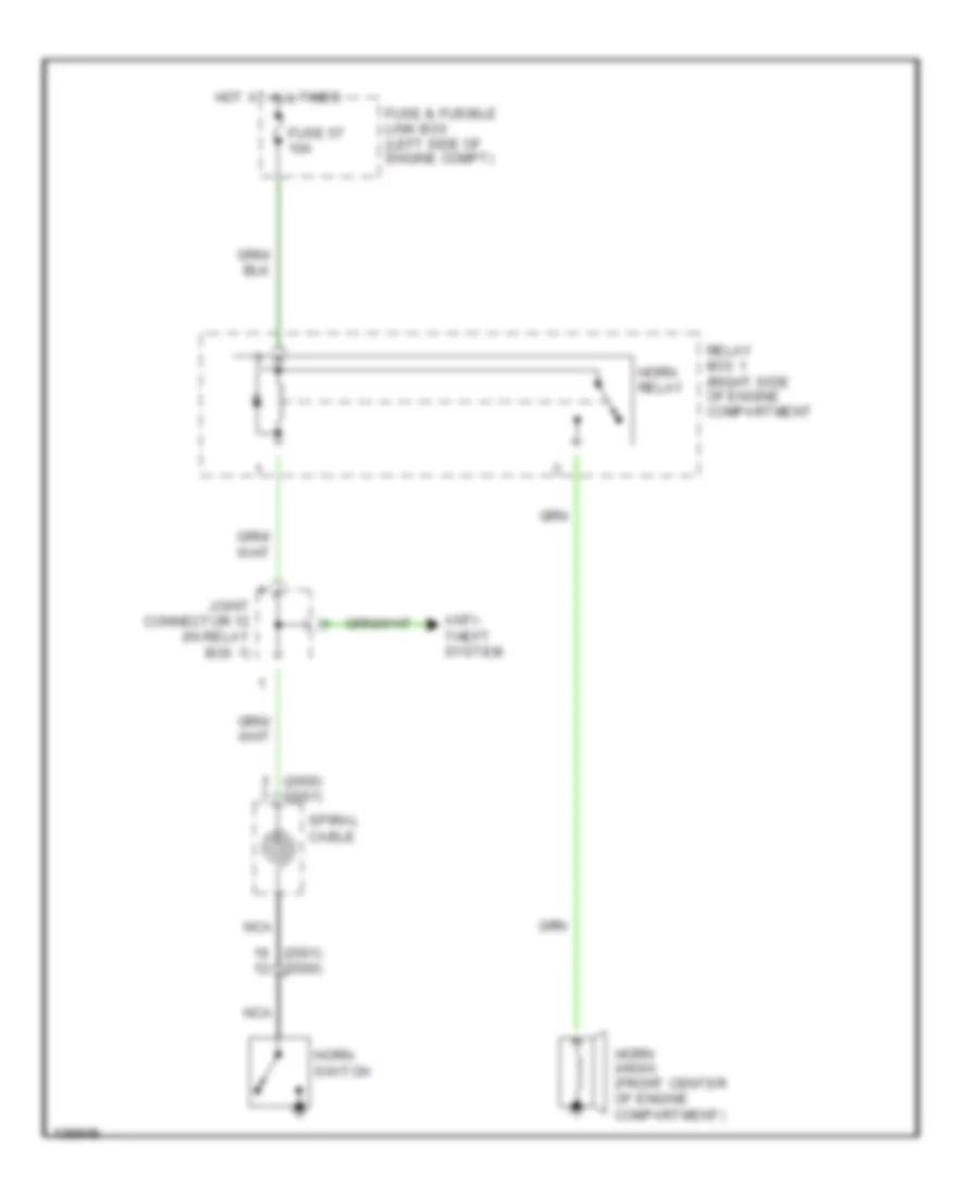
HORN
Horn Wiring Diagram for Nissan Maxima GLE 2000
List of elements for Horn Wiring Diagram for Nissan Maxima GLE 2000:
- (2000) (2001)
- (2001) (2000)
- Anti- theft system
- Fuse & fusible link box (left side of engine compt)
- Fuse 57 10a
- Horn (high) (front center of engine compartment)
- Horn relay
- Horn switch
- Hot at all times
- Joint connector 12 (in relay box 1)
- Nca
- Relay box 1 (right side of engine compartment
- Spiral cable
INSTRUMENT CLUSTER
Instrument Cluster Wiring Diagram (1 of 2) for Nissan Maxima GLE 2000
List of elements for Instrument Cluster Wiring Diagram (1 of 2) for Nissan Maxima GLE 2000:
- (with speedometer & odometer/trip meter)
- 10k
- Abs ind
- Air bag ind
- Brake ind
- Charge ind
- Combination meter
- Cruise ind
- Door ind
- Exterior lights system
- Fuel gauge
- Fuel ind
- Fuel level sensor unit & fuel pump (fuel tank)
- Fuse 12 10a
- Fuse 30 10a
- Fuse block (j/b) (behind left side of dash)
- G100 (front of left front fender)
- G202 (left end of dash)
- G312 (behind left rear seat)
- Headlights system
- Hot at all times
- Hot in on or start
- Interior lights system
- Left turn ind
- M32
- M33
- M34
- Malfunction ind
- Meter illum (x4 bulbs)
- O/d off ind
- Odo/trip meter ind
- Oil press ind
- Oil pressure switch (right front side of oil pan)
- Park/neutral position switch (on left rear side of transaxle)
- Red
- Right turn ind
- Seat belt ind
- Slip ind
- Speedometer
- Starting/ charging system
- Tachometer
- Thermal transmitter (top left rear of engine)
- Unified meter control unit
- Vehicle speed sensor (a/t) (top right rear of transaxle)
- Vehicle speed sensor (m/t) (top right side of clutch housing)
- Washer ind
- Washer level switch (fluid reservoir)
- Water temp gauge
Instrument Cluster Wiring Diagram (2 of 2) for Nissan Maxima GLE 2000
List of elements for Instrument Cluster Wiring Diagram (2 of 2) for Nissan Maxima GLE 2000:
- (canada only)
- (left "b" pillar) g308
- (lower left "b" pillar) g308
- (right "b" pillar) g305
- 14d
- Abs sila
- Abs/tcs control unit (behind left kick panel)
- Air bag diagnosis sensor unit (under rear of center console)
- Ascd control unit (behind lower center of dash)
- Brake fluid level switch (on master cylinder reservoir)
- Combination meter
- Cruise lmp out
- Diode
- Door sw (as)
- Door sw (dr)
- Door sw all
- Driver's seat belt buckle switch (in seat belt buckle)
- Engine control module (ecm) (behind instrument lower cover)
- G100 (front of left front fender)
- Ground a
- Headlights system
- Hi beam ind
- Led-r
- Left front door switch
- Left rear door switch
- Parking brake switch (base of parking brake lever)
- Red
- Right front door switch
- Right rear door switch
- Seat belt sw
- Seat belt w/l
- Set
- Set lamp out
- Slip sila
- Smart entrance control unit (behind center of dash)
- Speed sens
- Tach out
- Tcs off ind
- Tcs off sila
- Transmission control module (tcm) (behind lower center of dash)
- Vsp
- Vsp in
- W/ sunroof
- W/l (led)
- W/o sunroof
INTERIOR LIGHTS
Courtesy Lamps Wiring Diagram for Nissan Maxima GLE 2000
List of elements for Courtesy Lamps Wiring Diagram for Nissan Maxima GLE 2000:
- 10h
- 12l
- Bat (c/b)
- Bat (fuse)
- Bat saver out
- Circuit breaker (behind left side of dash)
- Combination meter
- Diode
- Door
- Door lock sw
- Door sw (as)
- Door sw (dr)
- Door sw all
- Fuse 10a
- Fuse block (behind left side of dash)
- G200 (left kick panel)
- G202 (left side of dash)
- G203 (right kick panel)
- G308 (lower left "b" pillar)
- G407 (center rear of trunk)
- G905 (right "c" pillar)
- Gnd
- Hot at all times
- Hot in on or start
- Ign
- Ignition keyhole illumination
- Interior lamp
- Key light out
- Key sw
- Key switch
- Left front door lock actuator (door unlock sensor)
- Left front door switch
- Left front step lamp
- Left rear door switch
- Left vanity mirror
- Off
- Red
- Right front door switch
- Right front step lamp
- Right rear door switch
- Right vanity mirror
- Room lamp out
- Smart entrance control unit (behind center of dash)
- Spot lamp
- Trunk room lamp
- Trunk room lamp switch
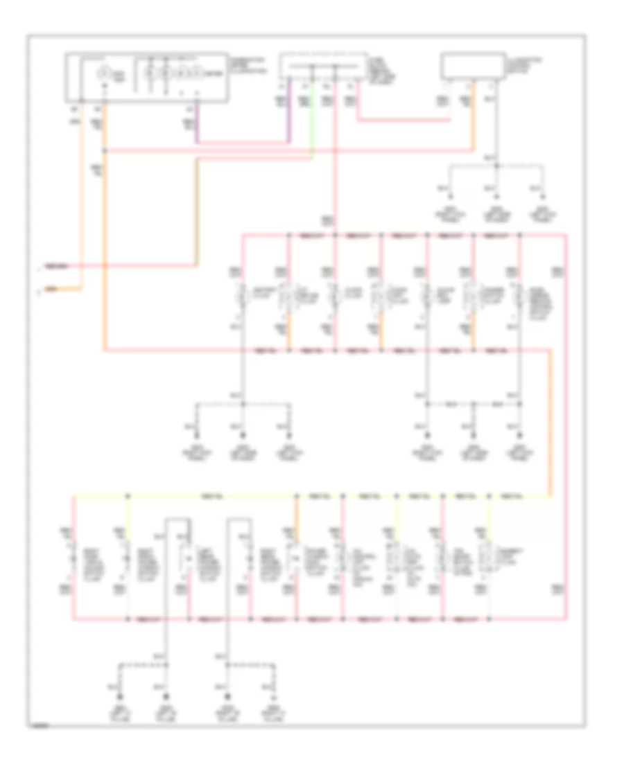
Instrument Illumination Wiring Diagram (1 of 2) for Nissan Maxima GLE 2000
List of elements for Instrument Illumination Wiring Diagram (1 of 2) for Nissan Maxima GLE 2000:
- 10k
- 12l
- 1st
- 2nd
- Auto
- Auto light control unit
- Bat
- Bat (c/b)
- Bat (fuse)
- Circuit breaker (behind left side of dash)
- Combination switch (lighting switch)
- Diode
- Door sw (as)
- Door sw (dr)
- Fuse 10a
- Fuse & fusible link box (at left side of engine compartment)
- Fuse block (behind left side of dash)
- G100 (front of left front fender)
- G101 (front of right front fender)
- G200 (left kick panel)
- G202 (left side of dash)
- G203 (right kick panel)
- G305 (right "b" pillar)
- G308 (lower left "b" pillar)
- G905 (right "c" pillar)
- Gnd
- Headlamp battery saver control unit (behind left side of dash)
- Hot at all times
- Hot in on or start
- Ign
- Ign sw
- J/c 13 (in relay box 1)
- Left front door switch
- Off
- Rap
- Rap out
- Right front door switch
- Smart entrance control unit (behind center of dash)
- T/l rly
- T/l sw1
- T/l sw2
- Taillamp relay (in relay box 1)
Instrument Illumination Wiring Diagram (2 of 2) for Nissan Maxima GLE 2000
List of elements for Instrument Illumination Wiring Diagram (2 of 2) for Nissan Maxima GLE 2000:
- 16l
- A/c auto amp. (illum) (w/ auto a/c)
- A/c control unit (illum) (w/ manual a/c)
- A/t device (illum)
- Ashtray (illum)
- Audio unit (illum)
- Clock (illum)
- Combination meter (illumination)
- Door mirror remote control switch (illum)
- Fuse block (behind left side of dash)
- G200 (left kick panel)
- G202 (left side of dash)
- G203 (right kick panel)
- G305 (right "b" pillar)
- G308 (left "b" pillar)
- G904 (left "c" pillar)
- G905 (right "c" pillar)
- Glove box lamp
- Hazard switch (illum)
- Illumination control switch
- Indirect lamp (illum)
- Left rear power window switch (illum)
- Meter
- Odo/ trip
- Power window main switch (illum)
- Right door lock & unlock switch (illum)
- Right front power window switch (illum)
- Right rear power window switch (illum)
- Tcs on/off switch (illum) (w/tcs)
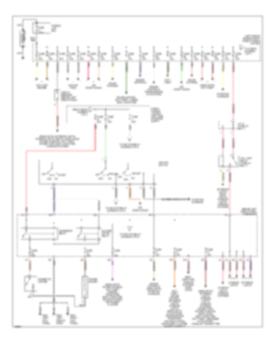
POWER DISTRIBUTION
Power Distribution Wiring Diagram (1 of 2) for Nissan Maxima GLE 2000
List of elements for Power Distribution Wiring Diagram (1 of 2) for Nissan Maxima GLE 2000:
- (behind left side of dash) fuse block
- (left side of engine compt) fuse & fusible link box
- Acc
- Accessory relay
- Air conditioning
- Anti- theft
- Anti- theft, cruise control, exterior lights, interior lights, headlights, nvis system, transmissions, telephone, air conditioning, instrument cluster, engine controls
- Anti-lock brakes
- Battery
- Blower motor relay
- Body computer, warning systems, door locks
- Cigarette lighter
- Circuit breaker (behind left side of dash)
- Cooling fans
- Cruise control, anti-theft, horns, body computer
- Engine controls
- Engine controls, headlights, starting/ charging
- Engine controls, transmissions, nvis system
- Exterior lights
- Exterior lights, head- lights, interior lights, warning systems
- From fuse 60 a (diagram 1 of 1)
- Fuse & fusible link box (left side of engine compt)
- Fuse 10a
- Fuse 15a
- Fuse a 120a
- Fuse b 80a
- Fuse c 40a
- Fuse d 40a
- Fuse e 40a
- Fuse g 40a
- Fuse h 40a
- Fuse i 40a
- Fuse j 80a
- Fusible link box
- G200 (left kick panel)
- G202 (left side of dash)
- G203 (right kick panel)
- Headlights, anti-theft
- Headlights, exterior lights, interior lights, seats, door locks, power windows, anti-theft, power tops, body computer, warning systems
- Headlights, exterior lights, interior lights, warning systems, power tops, power windows, door locks, body computer, anti-theft, defogger, nvis system, homelink transmitter
- Headlights, power antenna, anti-theft, mirrors, telephone, body computer, sound systems, instrument cluster
- Ignition switch
- Interior lights
- Interior lights, warning systems
- J/c 13 (in relay box 1)
- Nca
- Off
- Pnk
- Power socket
- Red
- Sound systems
- Start
- Starting/ charging
- Tail lamp relay (in relay box 1)
- To fuse b (diagram 1 of 1)
- To ignition relay (diagram 2 of 2)
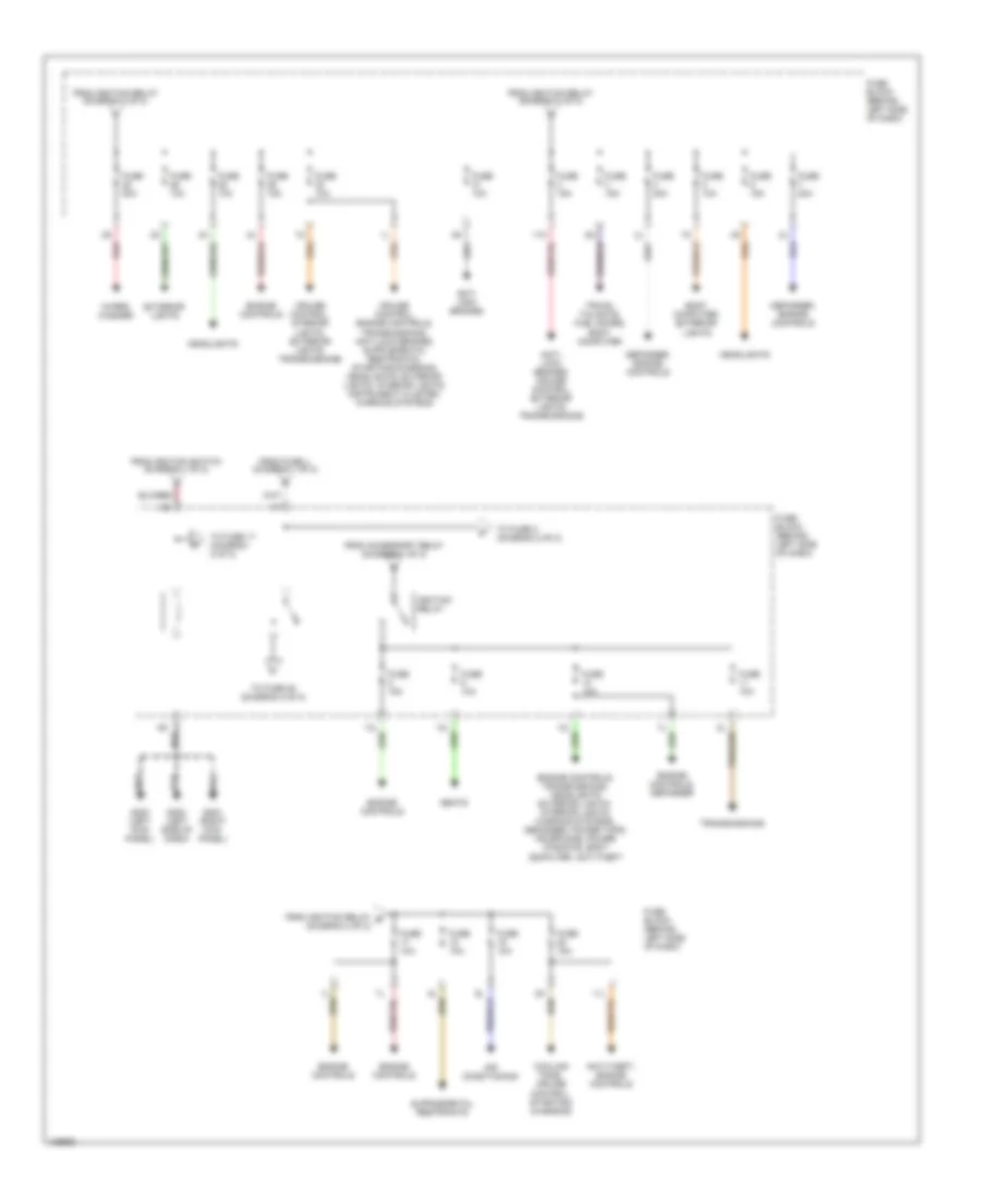
Power Distribution Wiring Diagram (2 of 2) for Nissan Maxima GLE 2000
List of elements for Power Distribution Wiring Diagram (2 of 2) for Nissan Maxima GLE 2000:
- 11k
- Air conditioning
- Anti- lock brakes
- Anti- lock brakes, cruise control, exterior lights, transmissions
- Anti-theft, engine controls
- Body computer, exterior lights
- Cooling fans, cruise control, starting/ charging
- Cruise control, interior lights, exterior lights, transmissions
- Defogger, engine controls
- Engine controls
- Engine controls, defogger
- Engine controls, transmissions, headlights exterior lights, interior lights, warning systems, defogger, power tops, telephone, power windows, body computer, anti-theft
- Exterior lights
- From accessory relay (diagram 1 of 2)
- From fuse j (diagram 1 of 2)
- From ignition relay (diagram 2 of 2)
- From ignition relay e (diagram 2 of 2)
- From ignition switch (diagram 1 of 2)
- Fuse 10a
- Fuse 15a
- Fuse 20a
- Fuse block (behind left side of dash)
- G200 (left kick panel)
- G202 (left side of dash)
- G203 (right kick panel)
- Headlights
- Ignition relay
- Red
- Seats
- To fuse 17 (diagram 2 of 2)
- To fuse 2 (diagram 2 of 2)
- To fuse 25 (diagram 2 of 2)
- Transmissions
- Trunk, tailgate, fuel doors, body computer
- Wiper/ washer
POWER DOOR LOCKS
Power Door Lock Wiring Diagram for Nissan Maxima GLE 2000
List of elements for Power Door Lock Wiring Diagram for Nissan Maxima GLE 2000:
- 10h
- 12k
- 12l
- Accessory
- Anti-theft system
- Battery (c/b)
- Battery (fuse)
- Battery saver out
- Between full stroke and n
- Central lock sw
- Central unlock sw
- Circuit breaker (behind left side of dash)
- Door lock output
- Door switch
- Door unlock out
- Dr condition sw
- Dr door switch
- Dr door unlock out
- Exterior lights system
- Full stroke
- Fuse 10a
- Fuse block (behind left side of dash)
- G200 (left kick panel)
- G203 (right kick panel)
- G305 (right "b" pillar)
- G308 (lower left "b" pillar)
- Ground
- Hazard output
- Hot at all times
- Hot in acc or on
- Hot in on or start
- Ignition
- Interior lights system
- Key cyl sw lock
- Key cyl sw unlock
- Key switch
- Left front door key cylinder switch
- Left front door lock actuator
- Left front door open
- Left rear door lock actuator
- Left rear door open switch
- Lock
- Locked
- Main power window & door lock & unlock switch
- Out
- Panic alarm output
- Pass condition sw
- Pass door switch
- Pnk
- Red
- Right door lock & unlock switch
- Right front door lock actuator
- Right front door open
- Right rear door lock actuator
- Right rear door open switch
- Room lamp output
- Smart entrance control unit (behind center of dash)
- Switch
- Unlock
- Unlocked
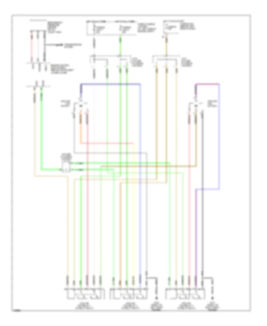
POWER MIRRORS
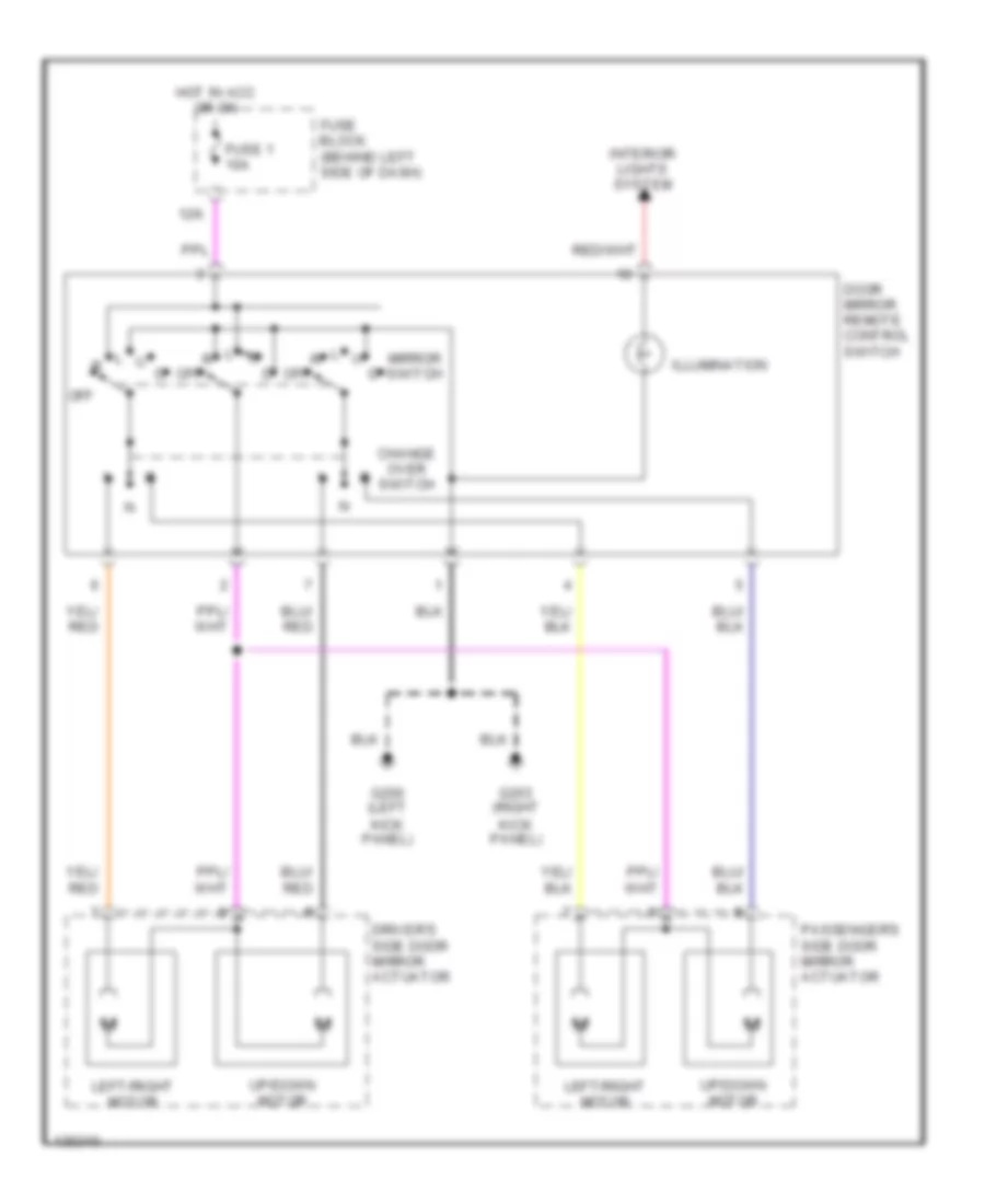
Power Mirror Wiring Diagram for Nissan Maxima GLE 2000
List of elements for Power Mirror Wiring Diagram for Nissan Maxima GLE 2000:
- 12k
- Change over switch
- Door mirror remote control switch
- Driver's side door mirror actuator
- Fuse 1 10a
- Fuse block (behind left side of dash)
- G200 (left kick panel)
- G203 (right kick panel)
- Hot in acc or on
- Illumination
- Interior lights system
- Left/right motor
- Mirror switch
- Off
- Passenger's side door mirror actuator
- Up/down motor
POWER SEATS
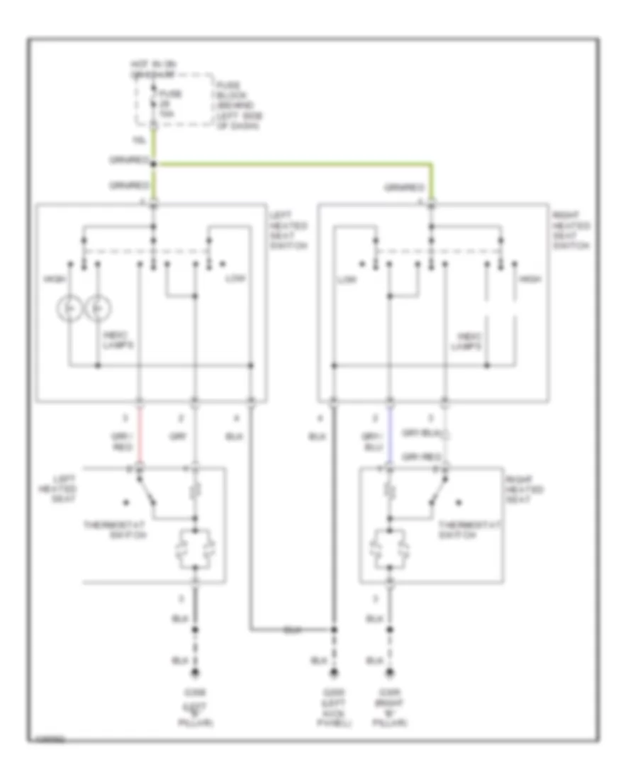
Heated Seats Wiring Diagram for Nissan Maxima GLE 2000
List of elements for Heated Seats Wiring Diagram for Nissan Maxima GLE 2000:
- (left "b" pillar)
- 10l
- Fuse 10a
- Fuse block (behind left side of dash)
- G200 (left kick panel)
- G305 (right "b" pillar)
- G308
- High
- Hot in on or start
- Indic lamps
- Left heated seat
- Left heated seat switch
- Low
- Right heated seat
- Right heated seat switch
- Thermostat switch
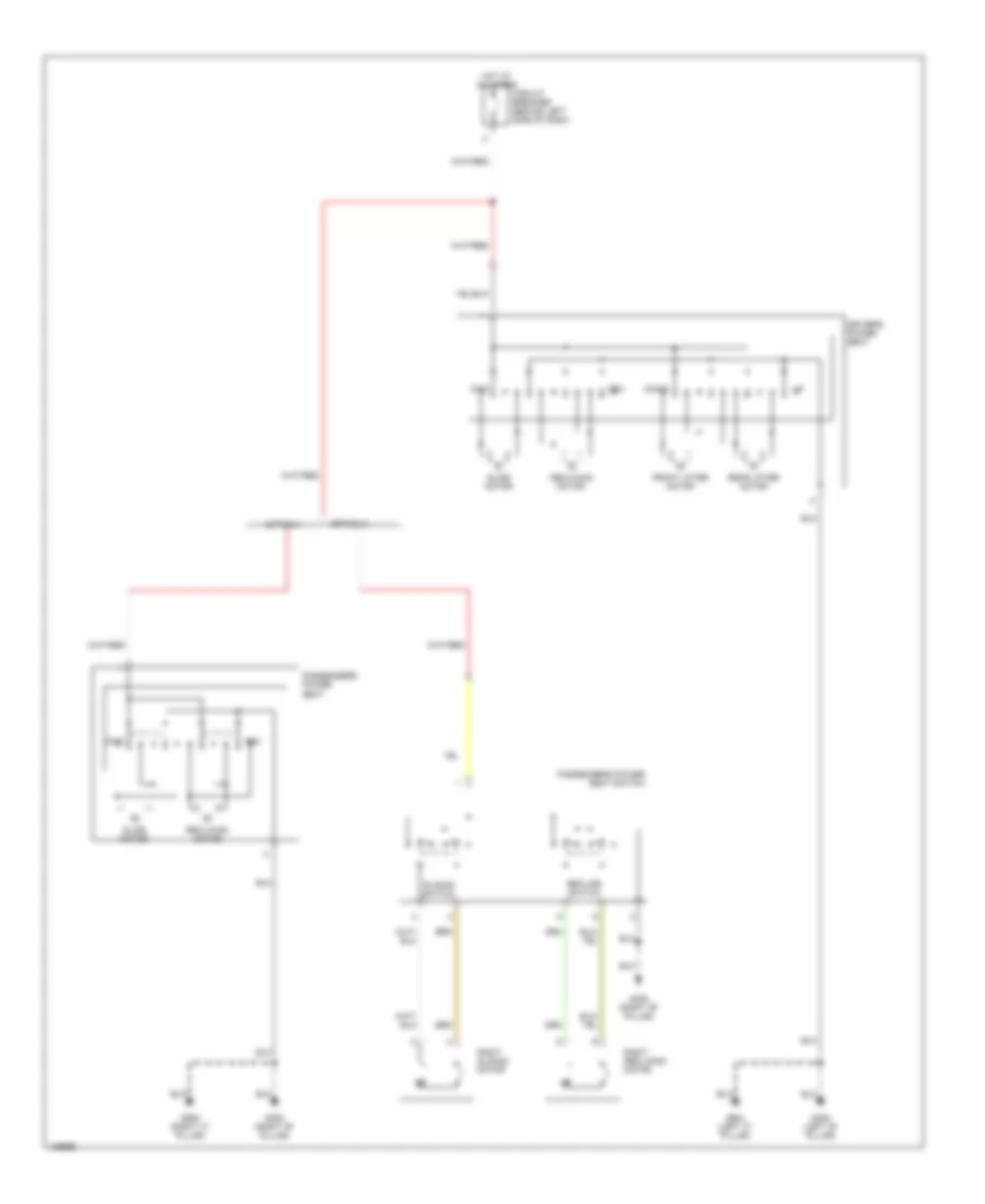
Power Seats Wiring Diagram for Nissan Maxima GLE 2000
List of elements for Power Seats Wiring Diagram for Nissan Maxima GLE 2000:
- Circuit breaker (behind left side of dash)
- Down
- Driver's power seat
- Front lifter motor
- Fwd
- G305 (right "b" pillar)
- G308 (left "b" pillar)
- G904 (left "c" pillar)
- G905 (right "c" pillar)
- Hot at all times
- Option 1
- Option 2
- Passenger's power seat
- Passenger's power seat switch
- Rear lifter motor
- Recline switch
- Reclining motor
- Rev
- Right reclining motor
- Right sliding motor
- Slide motor
- Sliding switch
POWER TOP/SUNROOF
Power Top/Sunroof Wiring Diagrams for Nissan Maxima GLE 2000
List of elements for Power Top/Sunroof Wiring Diagrams for Nissan Maxima GLE 2000:
- 12l
- Auto close
- Auto open
- Bat (c/b)
- Bat (fuse)
- Circuit breaker (behind left side of dash)
- Cpu
- Diode (behind left side of dash)
- Encoder
- Fuse & fusible link box (left side of engine compartment)
- Fuse 10a
- Fuse block (j/b) (behind left side of dash)
- Fuse i 40a
- G200 (left kick panel)
- G202 (left side of dash)
- Ground
- Hot at all times
- Hot in on or start
- Ignition
- Limit sw (slide)
- Limit sw (tilt)
- Pnk
- Rap output
- Red
- Slide switch
- Smart entrance control unit (behind center of dash)
- Sun roof motor (at front of sun roof opening)
- Sun roof switch
- Tilt switch
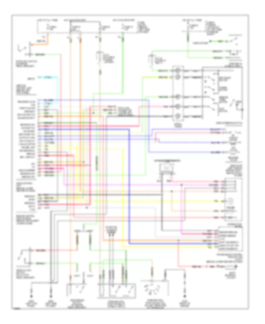
POWER WINDOWS
Power Window Wiring Diagram for Nissan Maxima GLE 2000
List of elements for Power Window Wiring Diagram for Nissan Maxima GLE 2000:
- 12l
- Auto d
- Auto u
- Bat (fuse)
- Circuit breaker (behind left side of dash)
- Cpu
- Diode (behind left side of dash)
- Driver side switch
- Encoder
- Full closed
- Fuse & fusible link box (left side of engine compartment)
- Fuse 10a
- Fuse block (j/b) (behind left side of dash)
- Fuse i 40a
- G200 (left kick panel)
- G202 (left side of dash)
- Ground
- Hot at all times
- Hot in on or start
- Ignition
- Left front power window regulator
- Left rear power window regulator
- Left rear power window switch
- Left rear switch
- Limit switch
- Other
- Power window main switch
- Power window relay (behind left side of dash)
- Rap output
- Red
- Right front power window regulator
- Right front power window switch
- Right front switch
- Right rear power window regulator
- Right rear power window switch
- Right rear switch
- Smart entrance control unit (behind center of dash)
- Unlk
- Window lock switch
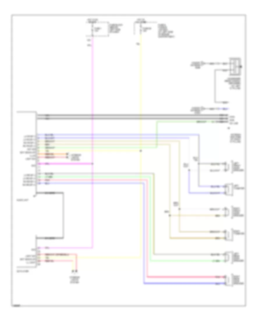
RADIO
Radio Wiring Diagrams, Base Radio for Nissan Maxima GLE 2000
List of elements for Radio Wiring Diagrams, Base Radio for Nissan Maxima GLE 2000:
- acc
- acc
- 12k
- Ant sig bat (back-up)
- Antenna amplifier (at right "c" pillar)
- Audio unit
- Bat (back-up)
- Cd player
- Condenser (rear window defogger) (at left "c" pillar)
- Dc line
- Din cord
- Fuse & fusible link box (at left side of engine compartment)
- Fuse 1 10a
- Fuse 56 15a
- Fuse block (behind left side of dash)
- Hot at all times
- Hot in on or acc
- Ill cont
- Illum light sw
- Interior lights system
- Left front door speaker
- Left rear door speaker
- Left tweeter
- Lh fr sp (-) lh fr sp (+)
- Lh rr sp (-) lh rr sp (+) rh rr sp (-) rh rr sp (+)
- Light sw
- Main
- Nca
- Pnk
- Rh fr sp (+)
- Rh fr sp (-)
- Right front door speaker
- Right rear door speaker
- Right tweeter
- Sub
- Window antenna (main)
- Window antenna (sub)
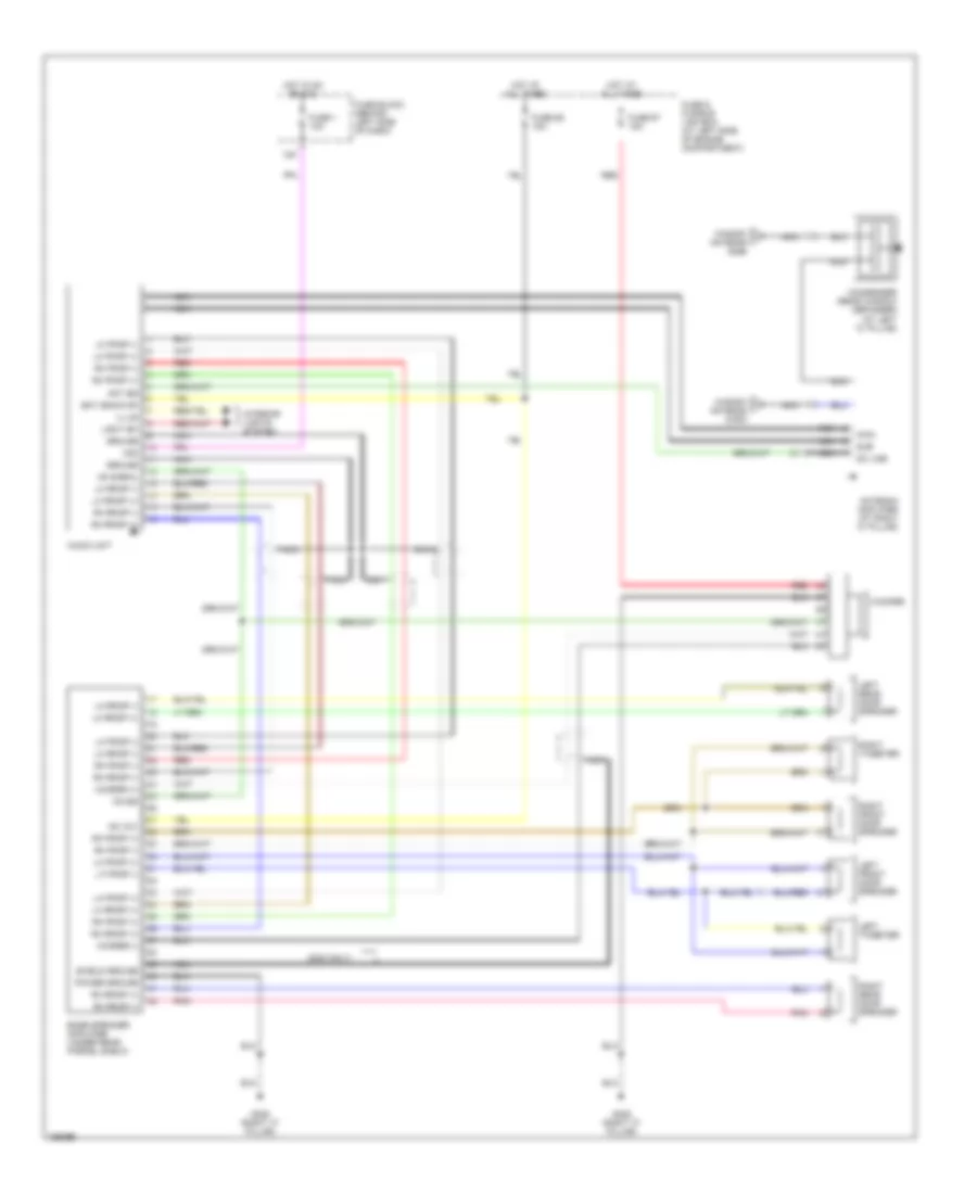
Radio Wiring Diagrams, with Bose System for Nissan Maxima GLE 2000
List of elements for Radio Wiring Diagrams, with Bose System for Nissan Maxima GLE 2000:
- (2000 only)
- +b (12v)
- 12k
- Acc
- Ant sig
- Antenna amplifier (at right "c" pillar)
- Audio unit
- Bat (back-up)
- Bose speaker amplifier (under rear parcel shelf)
- Condenser (rear window defogger) (at left "c" pillar)
- Dc line
- Fuse & fusible link box (at left side of engine compartment)
- Fuse 1 10a
- Fuse 56 15a
- Fuse 67 15a
- Fuse block (behind left side of dash)
- G305 (right "c" pillar)
- Ground
- Hot at all times
- Hot in on or acc
- Illum
- Interior lights system
- Left front door speaker
- Left rear door speaker
- Left tweeter
- Lf fr sp (-)
- Lh fr sp (+)
- Lh fr sp (+)
- Lh fr sp (-)
- Lh fr sp (-)
- Lh rr sp (+)
- Lh rr sp (+)
- Lh rr sp (-)
- Lh rr sp (-)
- Light sw
- Main
- Nca
- On sig
- On signal
- Pnk
- Power ground
- Red
- Rh fr sp (+)
- Rh fr sp (+)
- Rh fr sp (-)
- Rh fr sp (-)
- Rh rr sp (+)
- Rh rr sp (-)
- Rh rr sp (-)
- Right front door speaker
- Right rear door speaker
- Right tweeter
- Shield ground
- Sub
- Window antenna (main)
- Window antenna (sub)
- Woofer
- Woofer (+)
- Woofer (-)
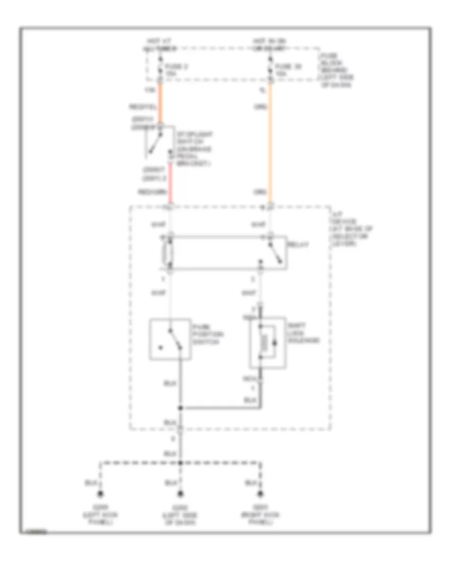
SHIFT INTERLOCKS
Shift Interlock Wiring Diagram for Nissan Maxima GLE 2000
List of elements for Shift Interlock Wiring Diagram for Nissan Maxima GLE 2000:
- (2000)
- (2001)
- 11k
- A/t device (at base of selector lever)
- Fuse 2 15a
- Fuse 30 10a
- Fuse block (behind left side of dash)
- G200 (left kick panel)
- G202 (left side of dash)
- G203 (right kick panel)
- Hot at all times
- Hot in on or start
- Nca
- Park position switch
- Relay
- Shift lock solenoid
- Stoplight switch (on brake pedal bracket)
STARTING/CHARGING
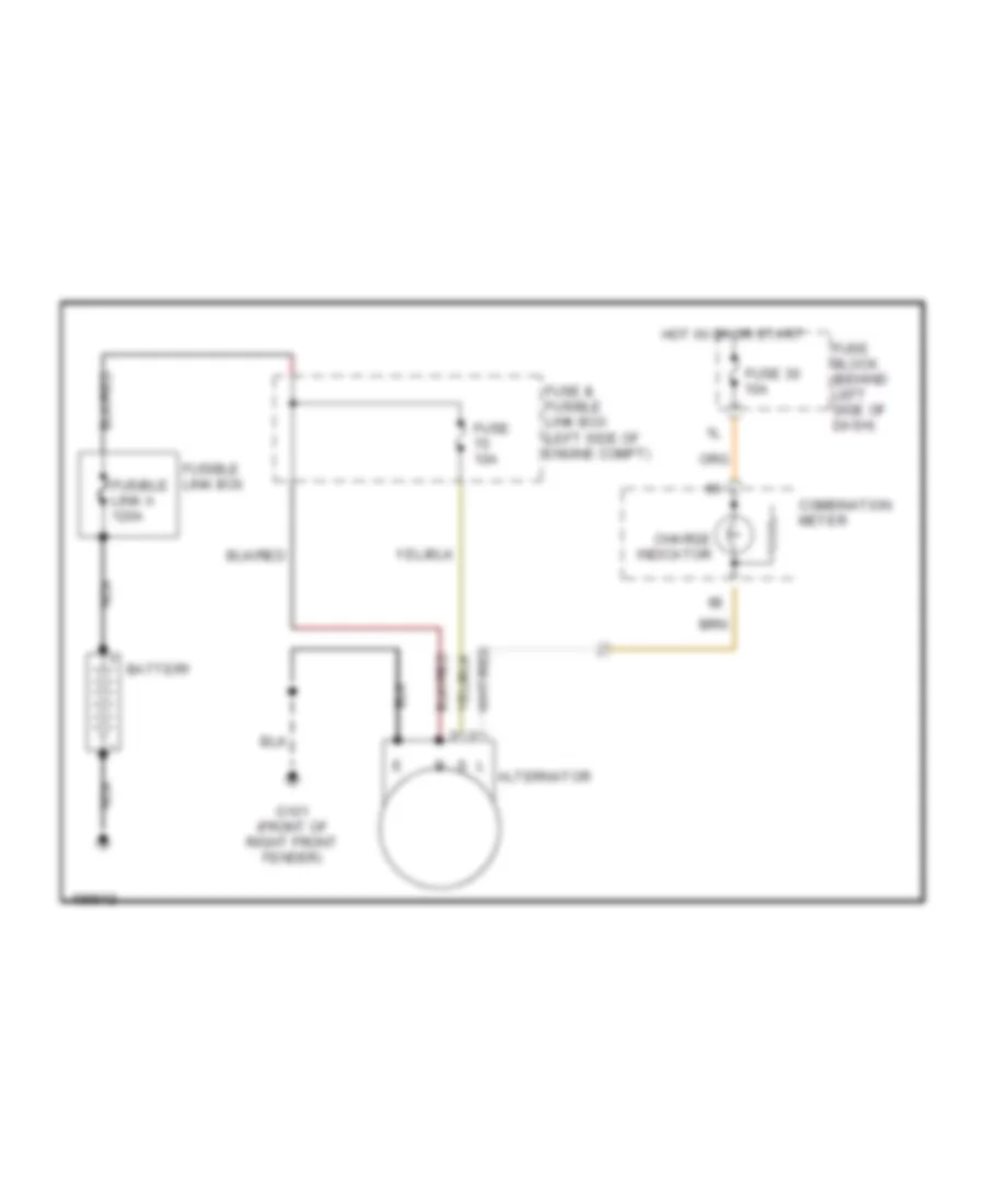
Charging Wiring Diagram for Nissan Maxima GLE 2000
List of elements for Charging Wiring Diagram for Nissan Maxima GLE 2000:
- Alternator
- Battery
- Charge indicator
- Combination meter
- Fuse & fusible link box (left side of engine compt)
- Fuse 10a
- Fuse 30 10a
- Fuse block (behind left side of dash)
- Fusible link a 120a
- Fusible link box
- G101 (front of right front fender)
- Hot in on or start
- Nca
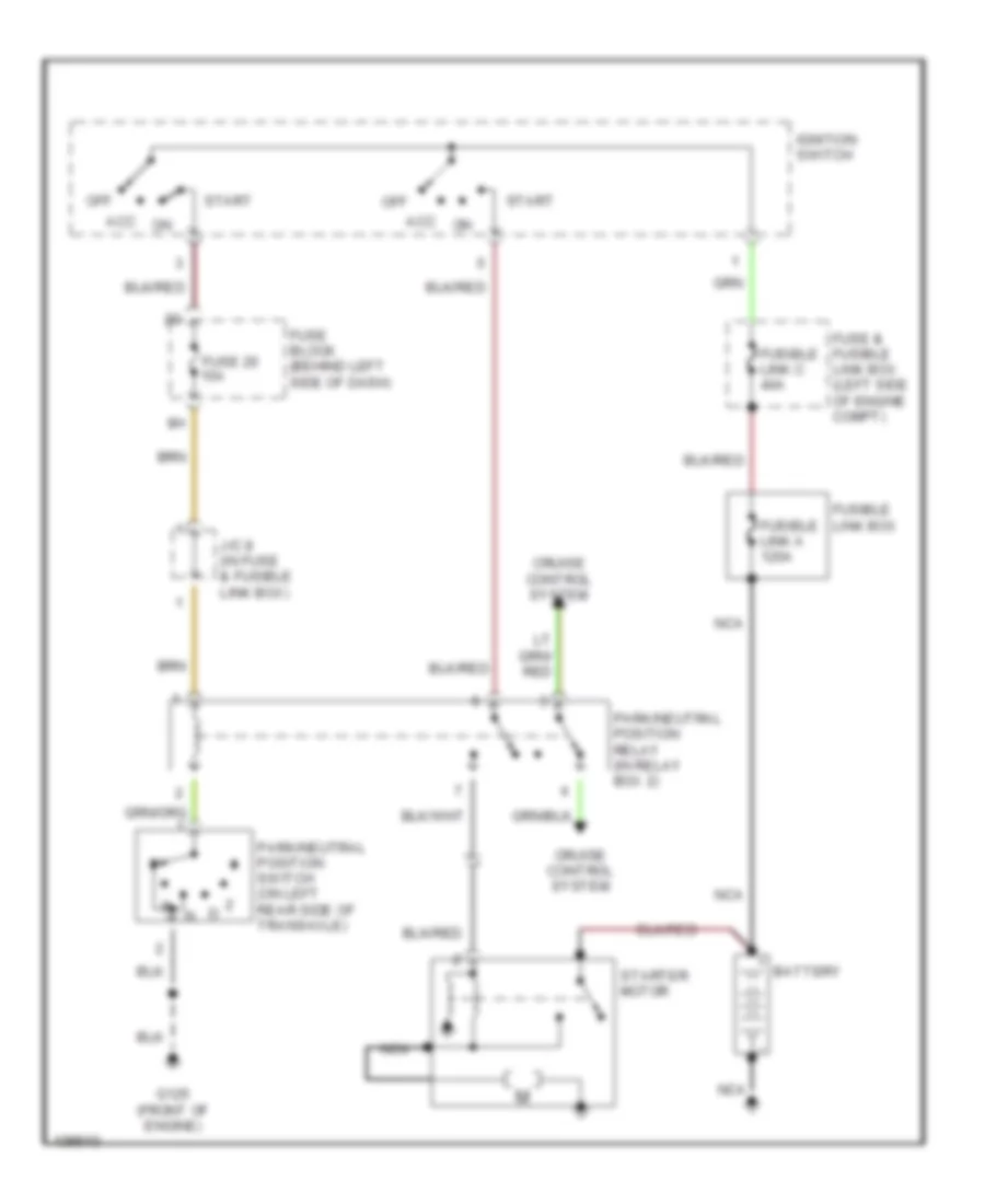
Starting Wiring Diagram, A/T for Nissan Maxima GLE 2000
List of elements for Starting Wiring Diagram, A/T for Nissan Maxima GLE 2000:
- Acc
- Battery
- Cruise control system
- Fuse & fusible link box (left side of engine compt)
- Fuse 20 15a
- Fuse block (behind left side of dash)
- Fusible link a 120a
- Fusible link box
- Fusible link c 40a
- G125 (front of engine)
- Ignition switch
- J/c 8 (in fuse & fusible link box)
- Nca
- Off
- Park/neutral position relay (in relay box 2)
- Park/neutral position switch (on left rear side of transaxle)
- Start
- Starter motor
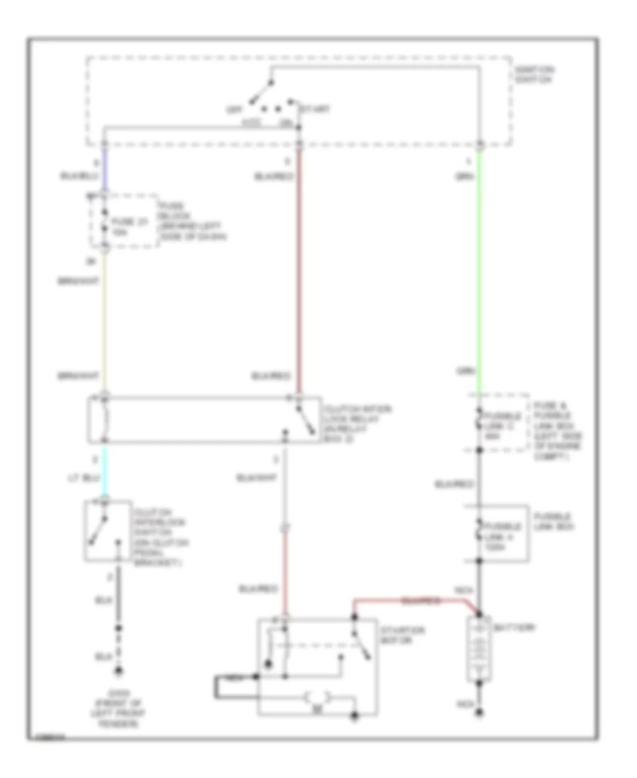
Starting Wiring Diagram, M/T for Nissan Maxima GLE 2000
List of elements for Starting Wiring Diagram, M/T for Nissan Maxima GLE 2000:
- Acc
- Battery
- Clutch inter- lock relay (in relay box 2)
- Clutch interlock switch (on clutch pedal bracket)
- Fuse & fusible link box (left side of engine compt)
- Fuse 21 10a
- Fuse block (behind left side of dash)
- Fusible link a 120a
- Fusible link box
- Fusible link c 40a
- G100 (front of left front fender)
- Ignition switch
- Nca
- Off
- Start
- Starter motor
SUPPLEMENTAL RESTRAINTS
Supplemental Restraint Wiring Diagram for Nissan Maxima GLE 2000
List of elements for Supplemental Restraint Wiring Diagram for Nissan Maxima GLE 2000:
- (behind left side of dash) g202
- (in middle of left "b" pillar) g308
- (in middle of right "b" pillar) g305
- Air bag diagnosis sensor unit (under rear of floor center console)
- Air bag ind
- Air bag ind.
- B135
- B42
- Closed
- Combination meter
- Data link connector (dlc) (partial) (under left side of dash)
- Door switch
- Driver air bag module
- Fasten
- Fuse 10a
- Fuse block (at left side of dash)
- Ground
- Hot in on or start
- Ignition
- Left front door switch
- Left lock +
- Left lock -
- Left satellite sensor (at base of left "b" pillar)
- Left seat belt buckle switch
- Left seat belt pretensioner
- Left side air bag module
- M112
- M32
- M33
- M34
- Nca
- Nca (in middle of left "b" pillar) g308
- Open
- Passenger air bag module
- Pnk
- Red
- Right lock +
- Right lock -
- Right satellite sensor (at base of right "b" pillar)
- Right seat belt pretensioner
- Right side air bag module
- Sat lh +
- Sat lh -
- Sat rh +
- Sat rh -
- Seat belt ind
- Seat belt indicator
- Seat belt sw
- Side rh +
- Spiral cable
- Sq as +
- Sq as -
- Sq dr +
- Sq dr -
- Sq pas +
- Sq pas -
- Sq pdr +
- Sq pdr -
- Sq rh -
- Sq side lh +
- Sq side lh -
- Sssrx
- Ssstx
- Un- fasten
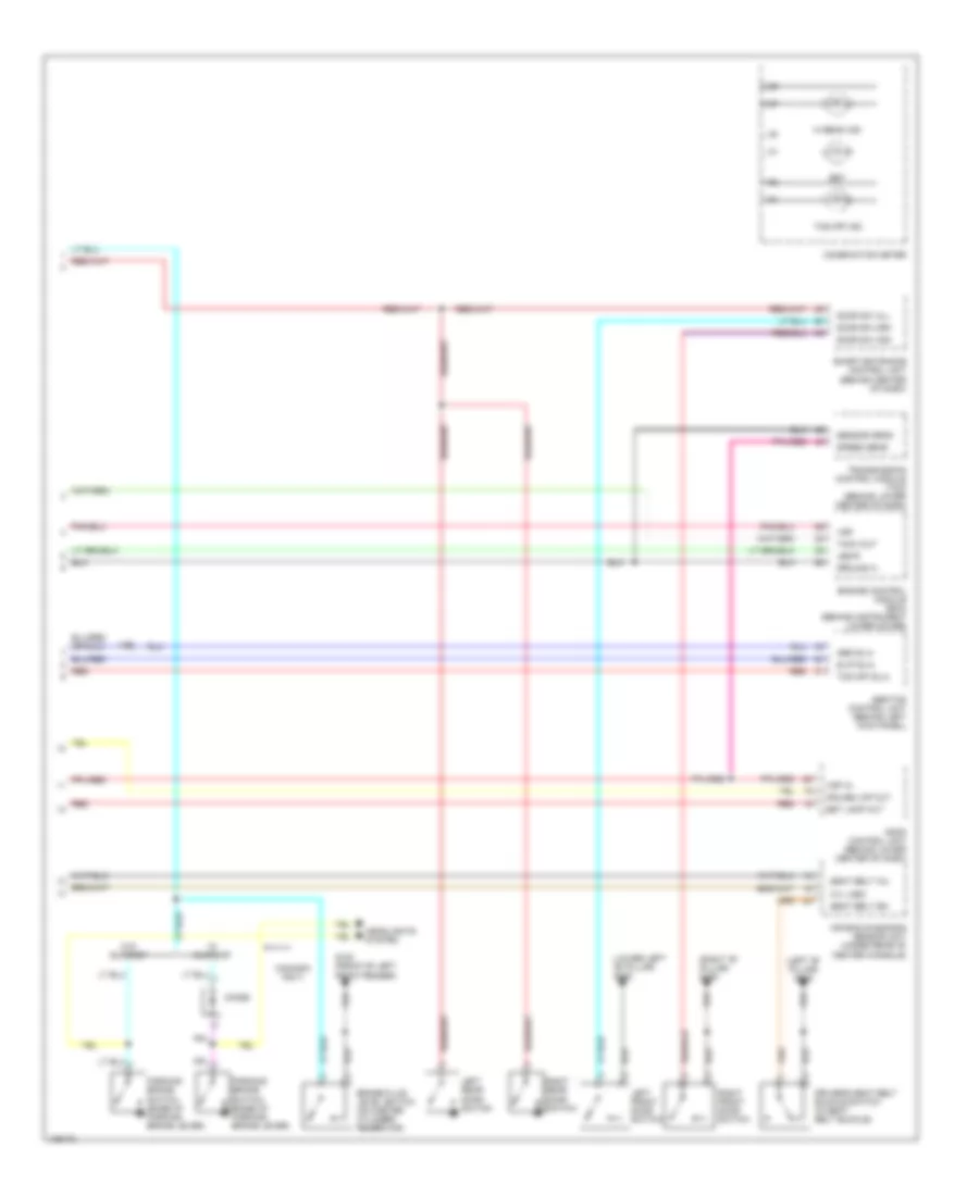
TRANSMISSION
Transmission Wiring Diagram for Nissan Maxima GLE 2000
List of elements for Transmission Wiring Diagram for Nissan Maxima GLE 2000:
- (left rear side trnsaxle) park/neutral position switch
- (lower left side of dash) data link connector
- (right side of engine compt)
- 1-sw
- 10k
- 11r
- 2-sw
- A/t device (overdrive control switch) (below front console)
- A/t fluid temp sensor
- Acsd
- Acsd 4th
- All times
- Ascd control unit (behind lower center of dash)
- Automatic transaxle
- Avcc
- Brake sw
- Closed throttle
- Combination meter
- D-sw
- Dropping resistor (near air cleaner box)
- Ecm relay (in relay box 2)
- Engine control module (ecm) (behind instrument lower cover)
- Exterior lights system
- Fld temp
- Full sw
- Fuse & fusible link box (left side of engine compt)
- Fuse 10a
- Fuse 11 10a
- Fuse 15a
- Fuse 59 15a
- Fuse block (behind left side of dash)
- G134 (top of engine)
- G201 (right side of dash)
- Gnd
- Gnd-a
- Hot at
- Hot in on or start
- Idle
- Idle sw
- J/c 12
- J/c 18 (behind center of dash)
- J/c 3 (behind left side of dash)
- Lan
- Line press sol valve
- Lu duty
- Mem b/u
- N-sw
- Nca
- O/d ind
- O/d off ind
- O/d sw
- Over- run clutch sol
- Ovr/c
- Pl duty
- Pnk
- R-sw
- Red
- Revolution sensor (right rear of transaxle)
- Sen pwr
- Sens gnd
- Shift a
- Shift b
- Shift sol valve a
- Shift sol valve b
- Sss in
- Sss out
- Stoplight switch (on bracket, above brake pedal)
- Tacho
- Tcc sol valve
- Throttle position switch (on throttle body assembly)
- Transmission control module (tcm) (behind lower center of dash)
- Ts in
- Tvo1
- Tvoo
- Unified meter control unit
- Vehicle speed sensor (on transaxle)
- Vign
- Vsp-1
- Vsp-2
- Wot
TRUNK, TAILGATE, FUEL DOOR
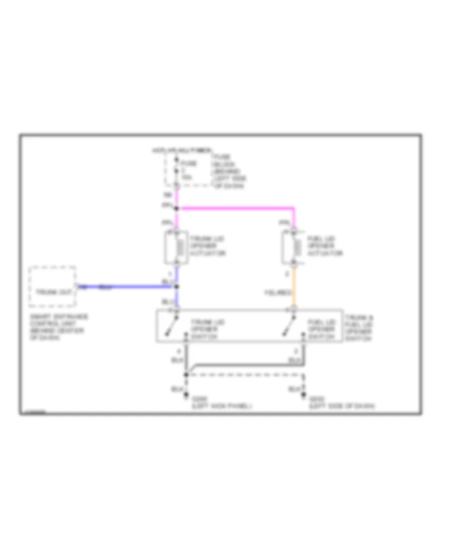
Trunk & Fuel Door Release Wiring Diagram for Nissan Maxima GLE 2000
List of elements for Trunk & Fuel Door Release Wiring Diagram for Nissan Maxima GLE 2000:
- Fuel lid opener actuator
- Fuel lid opener switch
- Fuse 15a
- Fuse block (behind left side of dash)
- G200 (left kick panel)
- G202 (left side of dash)
- Hot at all times
- Smart entrance control unit (behind center of dash)
- Trunk & fuel lid opener switch
- Trunk lid opener actuator
- Trunk lid opener switch
- Trunk out
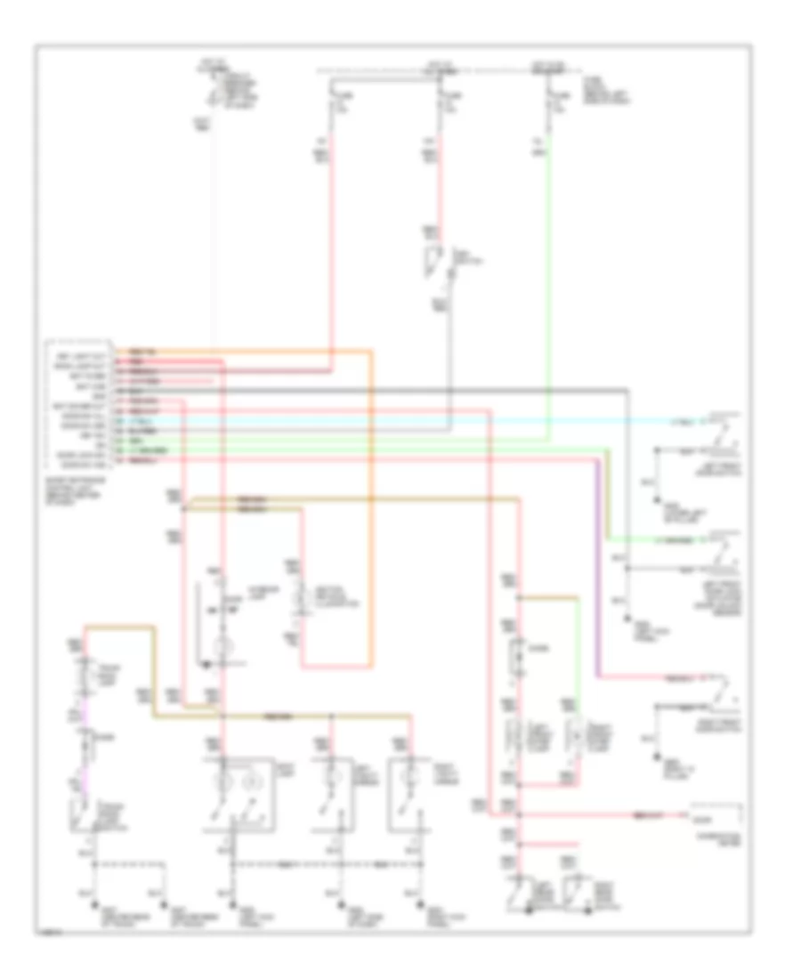
WARNING SYSTEMS
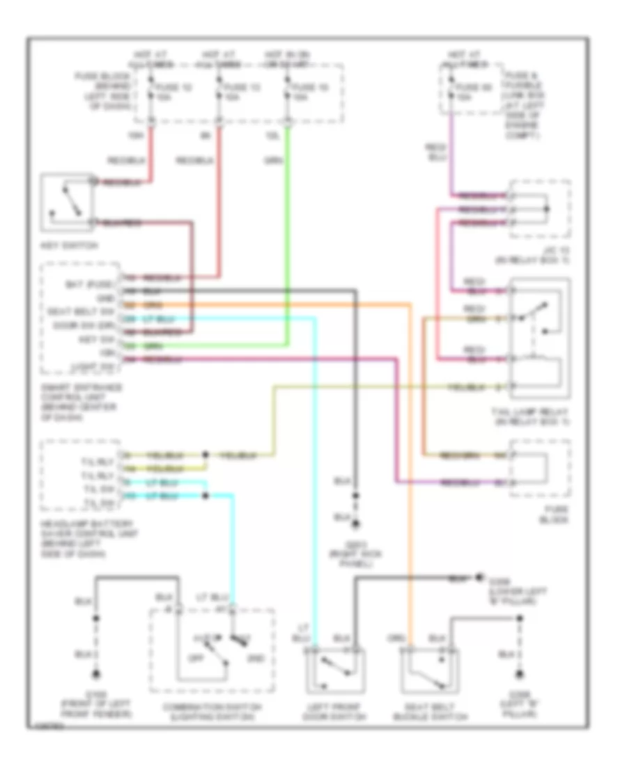
Warning System Wiring Diagrams for Nissan Maxima GLE 2000
List of elements for Warning System Wiring Diagrams for Nissan Maxima GLE 2000:
- 10h
- 12l
- 1st
- 2nd
- Auto
- Bat (fuse)
- Combination switch (lighting switch)
- Door sw (dr)
- Fuse & fusible link box (at left side of engine compt)
- Fuse 10 10a
- Fuse 12 10a
- Fuse 13 10a
- Fuse 60 10a
- Fuse block
- Fuse block (behind left side of dash)
- G100 (front of left front fender)
- G203 (right kick panel)
- G308 (left "b" pillar)
- G308 (lower left "b" pillar)
- Gnd
- Headlamp battery saver control unit (behind left side of dash)
- Hot at all times
- Hot in on or start
- Ign
- J/c 13 (in relay box 1)
- Key sw
- Key switch
- Left front door switch
- Light sw
- Off
- Seat belt buckle switch
- Seat belt sw
- Smart entrance control unit (behind center of dash)
- T/l rly
- T/l sw
- Tail lamp relay (in relay box 1)
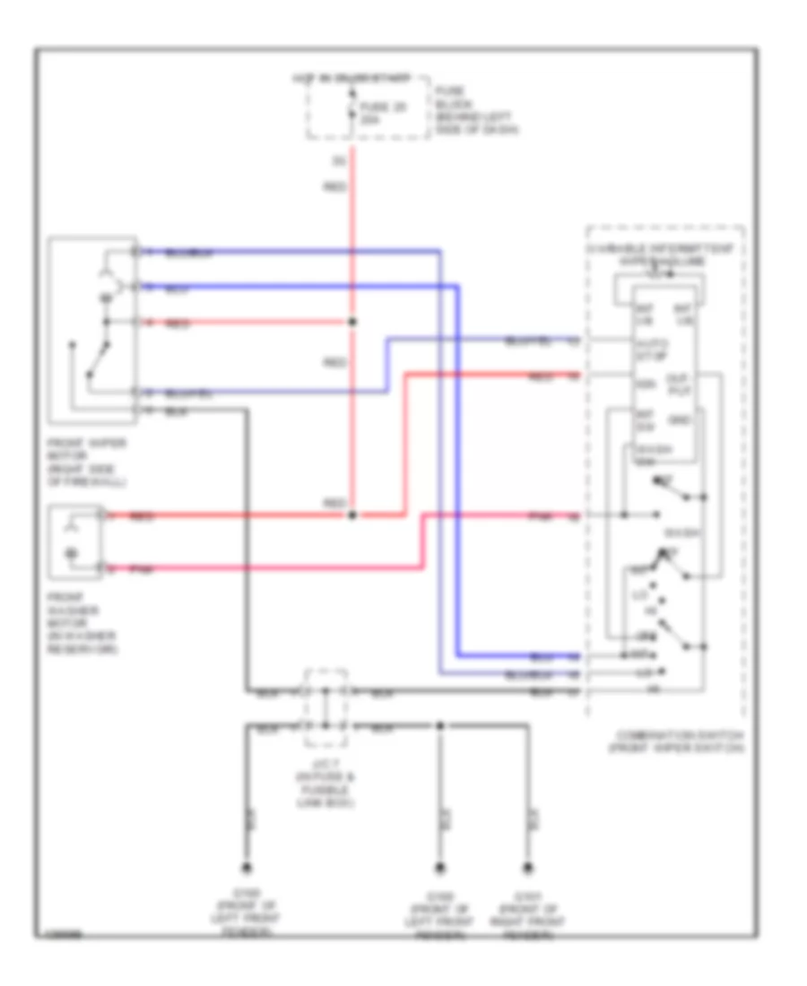
WIPER/WASHER
Wiper/Washer Wiring Diagram for Nissan Maxima GLE 2000
List of elements for Wiper/Washer Wiring Diagram for Nissan Maxima GLE 2000:
- Auto stop
- Combination switch (front wiper switch)
- Front washer motor (in washer reservoir)
- Front wiper motor (right side of firewall)
- Fuse 25 20a
- Fuse block (behind left side of dash)
- G100 (front of left front fender)
- G101 (front of right front fender)
- Gnd
- Hot in on or start
- Ign
- Int
- Int sw
- Int vr
- J/c 7 (in fuse & fusible link box)
- Off
- Out- put
- Pnk
- Red
- Variable intermittent wiper volume
- Wash
- Wash sw

 Čeština
 Dansk
Dansk Deutsch
 English
 English
 Español
 Suomi
Suomi Français
 Français
 עברית
עברית Hrvatski
 Magyar
 Italiano
 日本語
日本語 한국어
한국어 Nederlands
 Polski
 Português
 Português
 Română
 Русский
 Slovenčina
 Slovenščina
 Svenska
 Türkçe
 中文 (中国)