AIR CONDITIONING
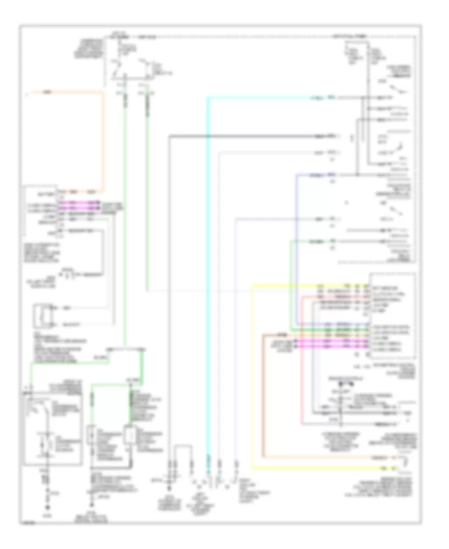
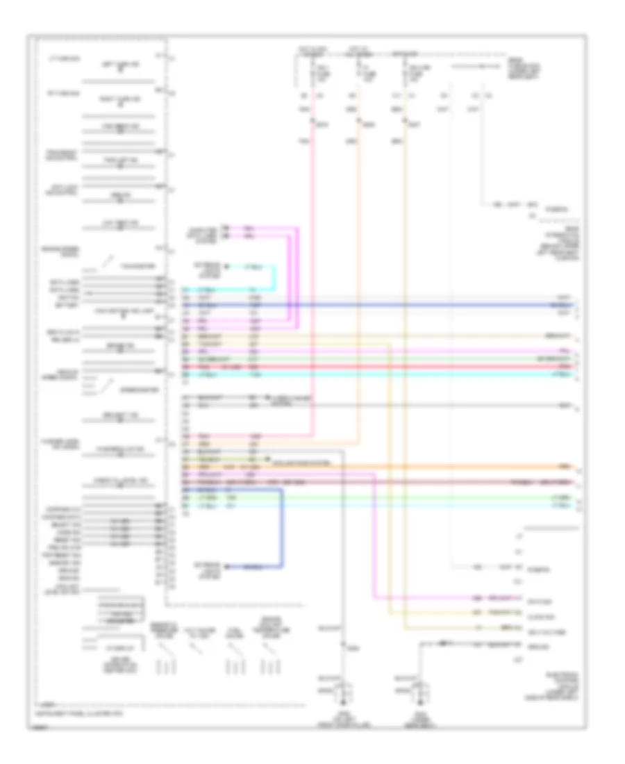
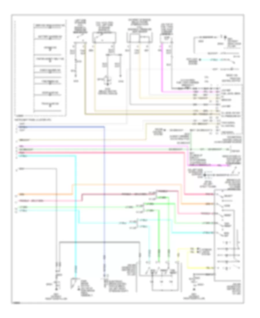
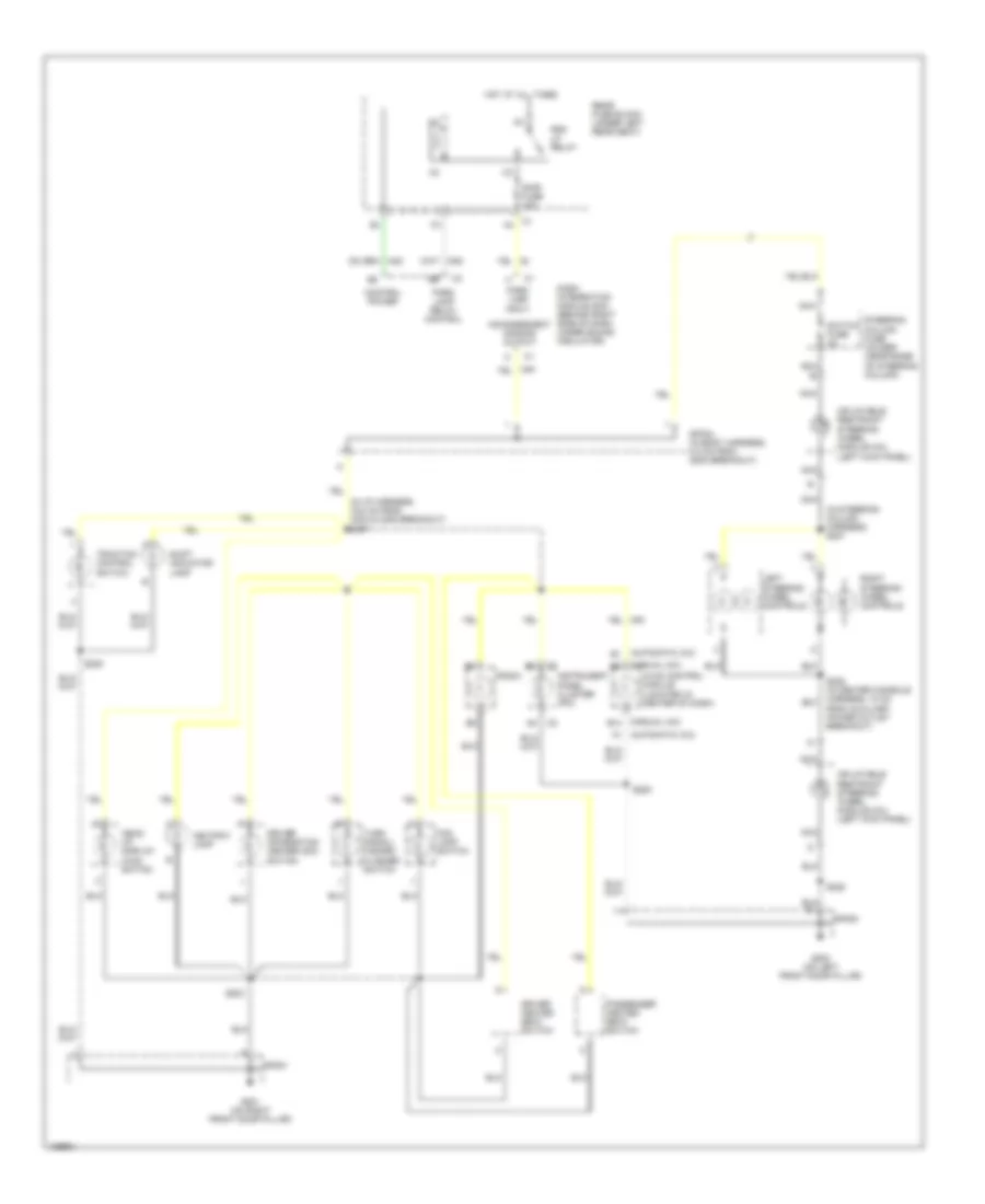
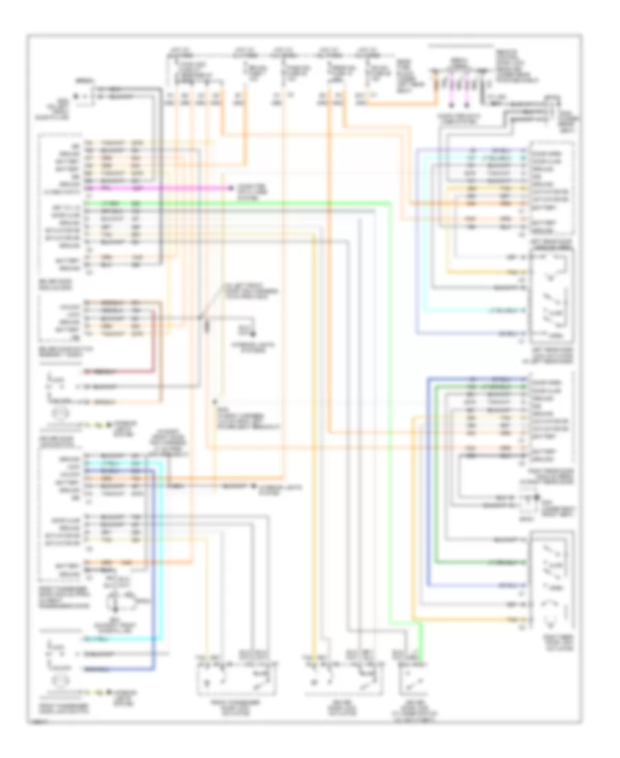
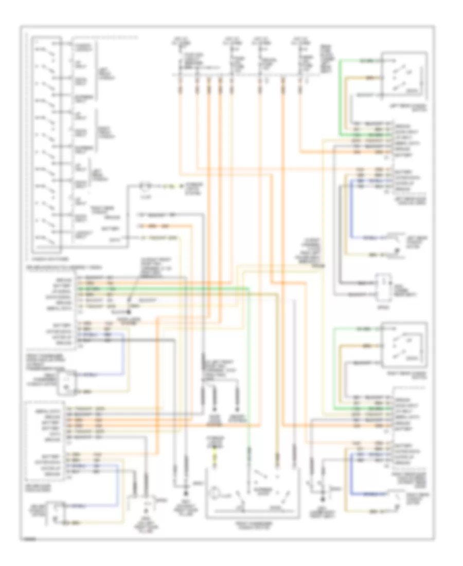
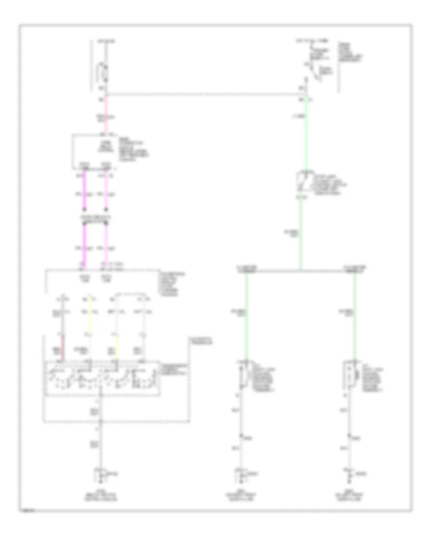
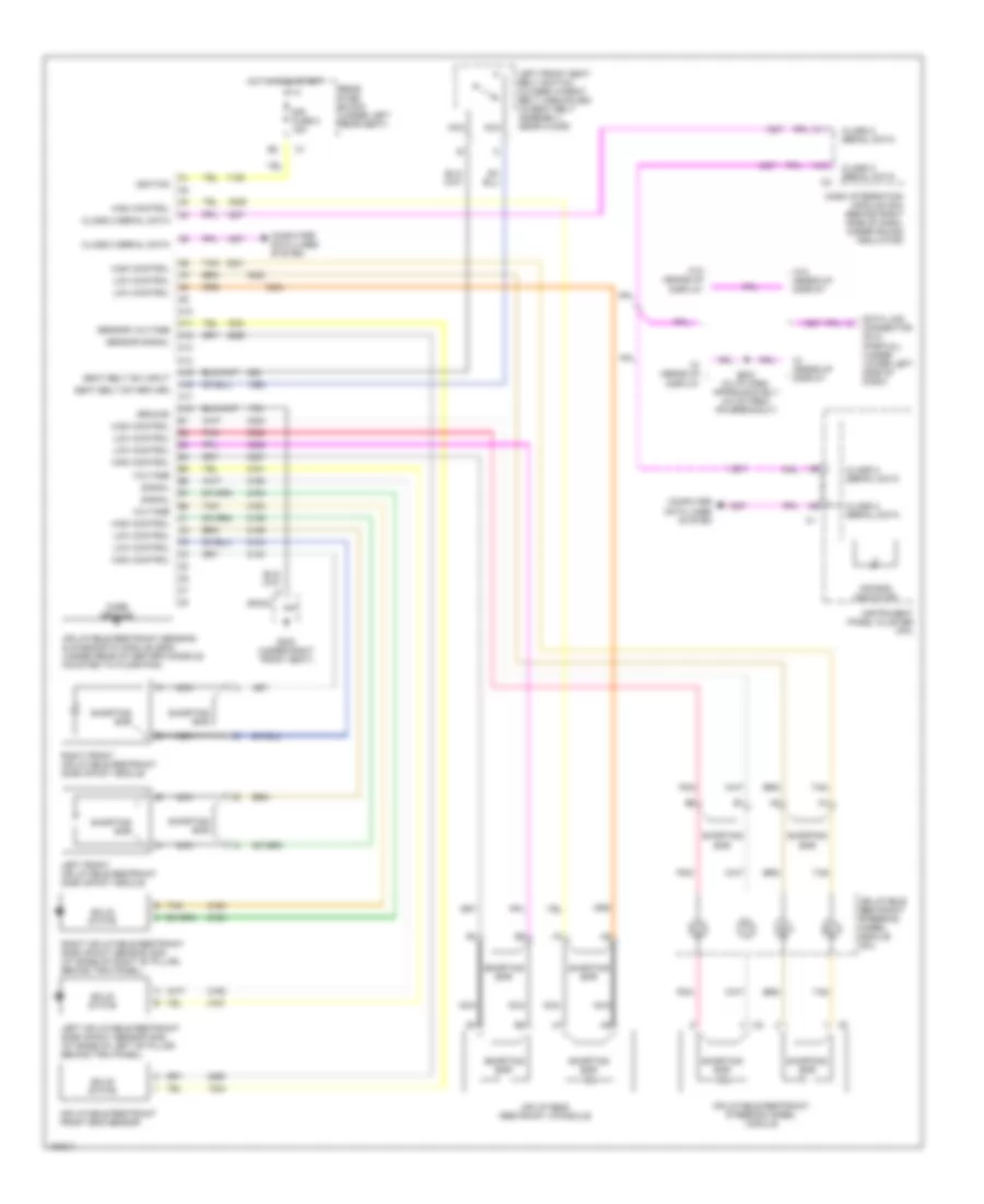
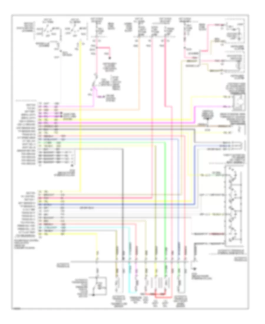
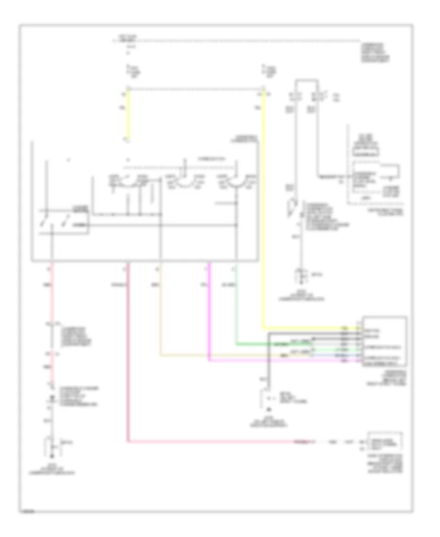
Automatic A/C Wiring Diagram (1 of 2) for Pontiac Bonneville SE 2004
 https://portal-diagnostov.com/license.html
Automotive Electricians Portal FZCO
Automotive Electricians Portal FZCO
https://portal-diagnostov.com/license.html
https://portal-diagnostov.com/license.html
Automotive Electricians Portal FZCO
Automotive Electricians Portal FZCO
List of elements for Automatic A/C Wiring Diagram (1 of 2) for Pontiac Bonneville SE 2004:
- (2 cm from instrument cluster breakout)
- (23.5 cm from c204 breakout)
- (in hvac harn, 30 cm from c204 breakout) s221
- (in hvac harness, 36.5 cm from c204 breakout)
- (in i/p harness, 35 cm cm from instrument cluster breakout)
- (mounted on right front of blower motor) blower motor control processor
- 5v ref
- A10
- A11
- A12
- Air mix act cntl
- Amb air temp sig
- Amb light sens
- Ambient air temperature sensor (at front center of engine compt, forward of radiator) upper left air temperature sensor (behind left air discharge vent)
- Backlight
- Bat pos volt
- Battery
- Blower motor (under right side of dash, above sound insulator)
- Blwr mtr gnd
- Blwr sp cntrl
- Blwr volt
- C1 a1
- C11
- C12
- C13
- C3 e11
- Class 2 serial
- Clock sig
- Computer data lines system
- D11
- D12
- D16
- Data sig
- Dim fuse 38 10a
- Drvr sun ld sens
- G200 (on left front door pillar)
- G201 (on right front door pillar)
- Gnd
- Ground
- Headlights system
- Hot at all times
- Hot in on
- Hvac batt fuse 37 10a
- Hvac blo fuse 2 30a
- Hvac control module (located in center of dash)
- Hvac fuse 33 10a
- Ign 3 rr fuse 34 10a
- Ign 3 volt
- Ign 3 voltage
- In air temp sig
- Inside air temperature sensor (on dash, right of steering column)
- Instrument panel integration module (behind left side of dash)
- Interior lights system
- Left air temperature actuator (on top left side of hvac assembly)
- Lft air temp dr
- Low lft temp sig
- Low ref
- Low rt temp sig
- Lower left air temperature sensor (behind left air discharge vent)
- Lower right air temperature sensor (behind right air discharge vent)
- Mode actuator (under left side of dash, on left side of hvac assembly)
- Mode dr ctrl
- Mode dr pos sens
- Mtr ctrl
- Mtr spd ctrl
- Nca
- Pass sun ld sens
- Rear fuse block (under left rear seat)
- Recirc dr ctrl
- Recirc dr pos
- Recirculation actuator (under right side of dash, to right of blower motor)
- Right air temperature actuator (behind glove box, on right side of hvac assembly)
- Rt air temp dr
- S203 (i/p harn, 6.5 cm from ipm breakout)
- S204
- S205
- S222
- S253 (in i/p wiring harness, 13 cm from turn signal hazard flasher module)
- Solid state
- Sp200
- Sp201
- Sunload sensor assembly (on top center of dash)
- Tan
- Up lft temp sig
- Up rt temp sig
- Upper right air temperature sensor (behind right air discharge vent)
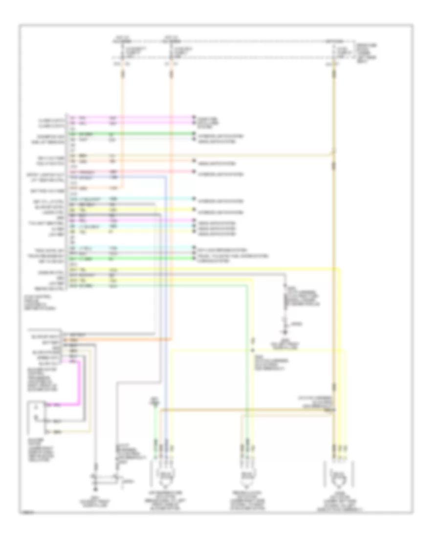
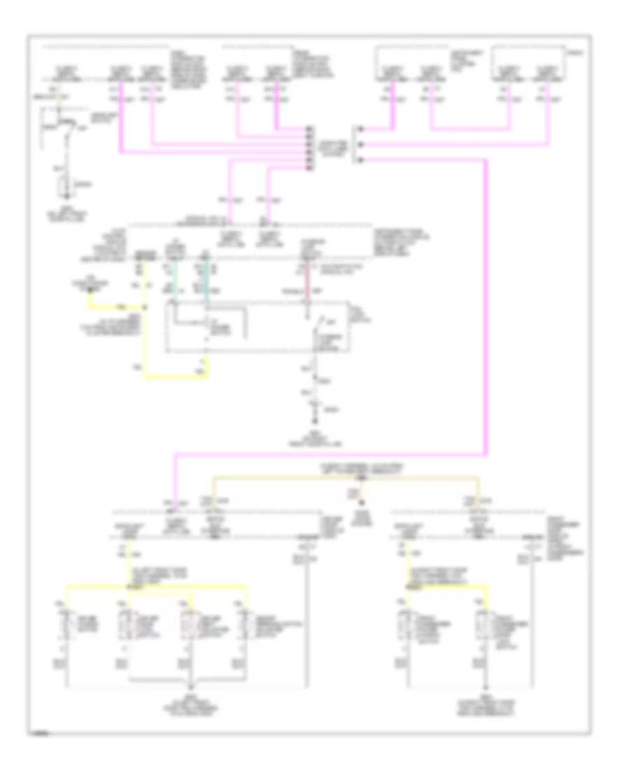
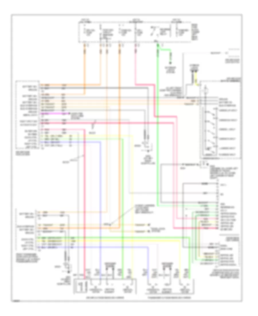
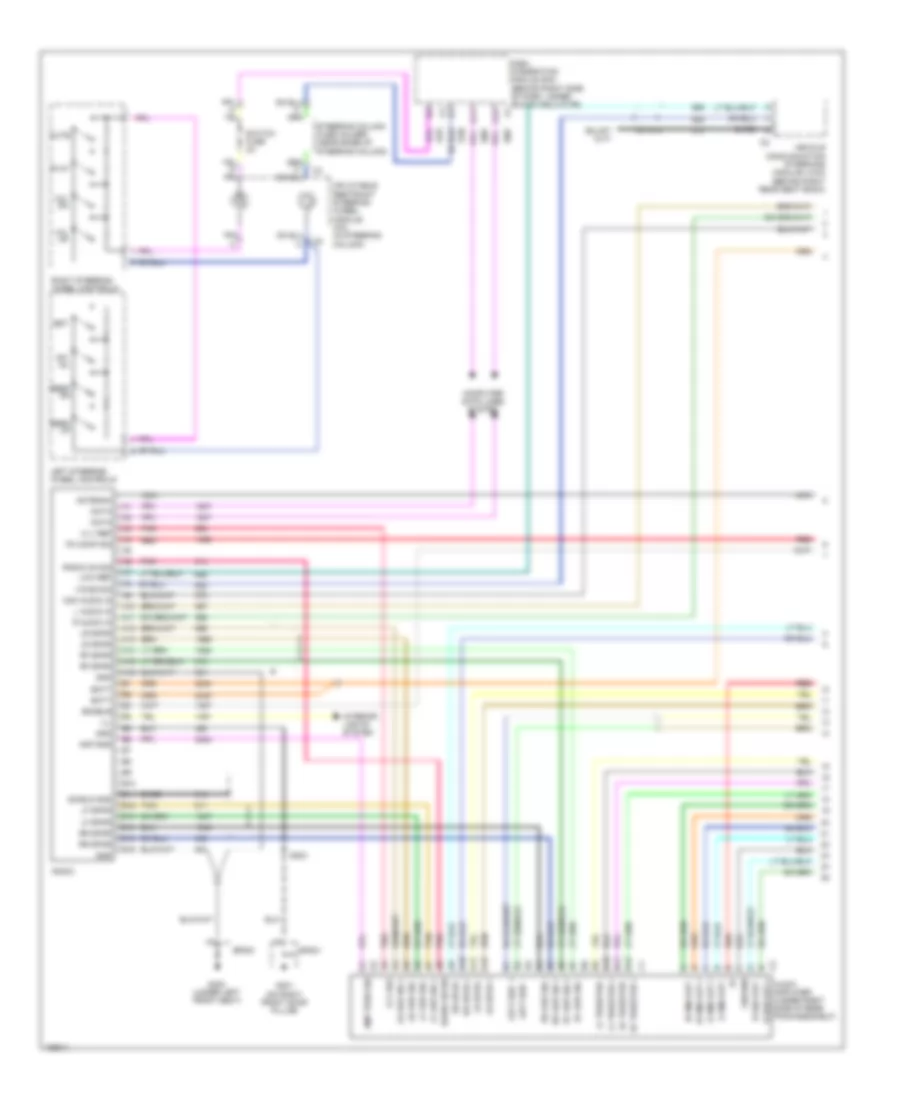
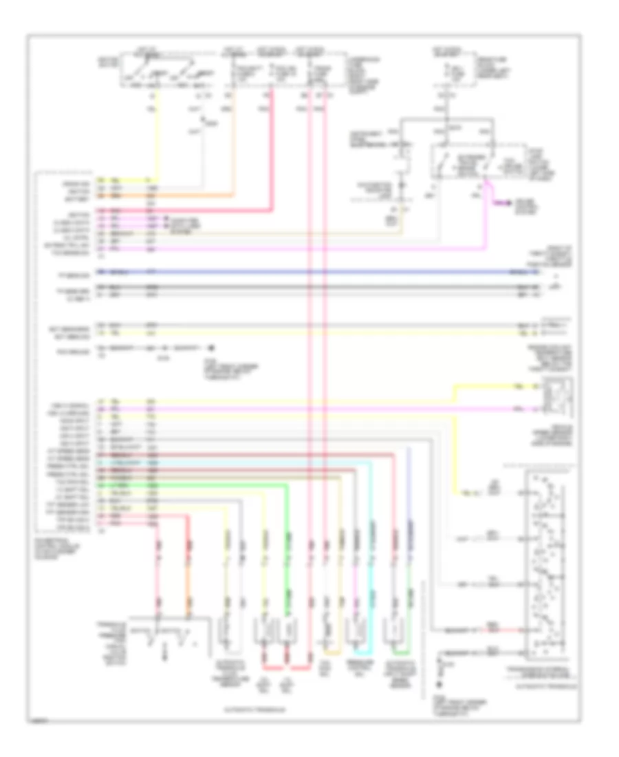
Automatic A/C Wiring Diagram (2 of 2) for Pontiac Bonneville SE 2004
List of elements for Automatic A/C Wiring Diagram (2 of 2) for Pontiac Bonneville SE 2004:
- ( in engine harness, 6.5 cm from idle air control valve connector breakout)
- (front of a/c compressor) a/c compressor clutch
- (high speed) coolfan 2 relay 37
- (in engine harness, 9.5 cm from pcm connector) s105
- 3.8l
- 3.8l 4.6l
- 4.6l
- 474 (or 2700)
- 5v ref
- 808 (or 2751)
- A/c clu fuse 26 15a
- A/c clu relay 32
- A/c compressor clutch (on front of a/c compressor)
- A/c compressor clutch diode (on wiring harness, near a/c compressor)
- A/c compressor clutch solenoid
- A/c compressor temperature switch
- A/c refrigerant low temperature sensor (4.6l) (rear center of engine, on high pressure line junction block to evaporator core)
- A/c refrigerant pressure sensor (behind a/c compressor, on a/c line)
- A10
- A11
- A11 class 2 serial a12 class 2 serial a6
- A12
- B10
- B11
- Battery
- C10
- C11
- Class 2 serial
- Clutch rly ctrl
- Computer data lines system
- Cool fan 1 fuse 47 30a
- Cool fan 2 fuse 46 30a
- Coolfan 1 relay (low speed)
- Coolfan s/p relay 39 (series/parallel)
- D10
- Dash integration module (dim) (behind right side of dash, under sound insulator)
- E10
- E11
- Ect sens sig
- Engine controls system
- Engine coolant temperature (ect) sensor (3.8l (vin k): on rear of engine, near thermostat housing) (4.6l (vin a): below throttle body)
- F11
- G10
- G103 (in front of underhood fuse block)
- G105 (below ignition control module)
- G11
- G180
- G200 (on left front door pillar)
- Gnd
- High spd fan cntrl
- Hot at all times
- Hot in on
- Left cooling fan (at left front of engine compt)
- Lo ref
- Low ref
- Low spd fan cntrl
- Nca
- Powertrain control module (in air cleaner housing)
- Right cooling fan (at right front of engine compt)
- S106
- S109
- S130
- Sens sig
- Sensor signal
- Sp103
- Sp105
- Sp200
- T10
- T11
- Underhood fuse block (right front side of engine compartment)
- V10
- V11
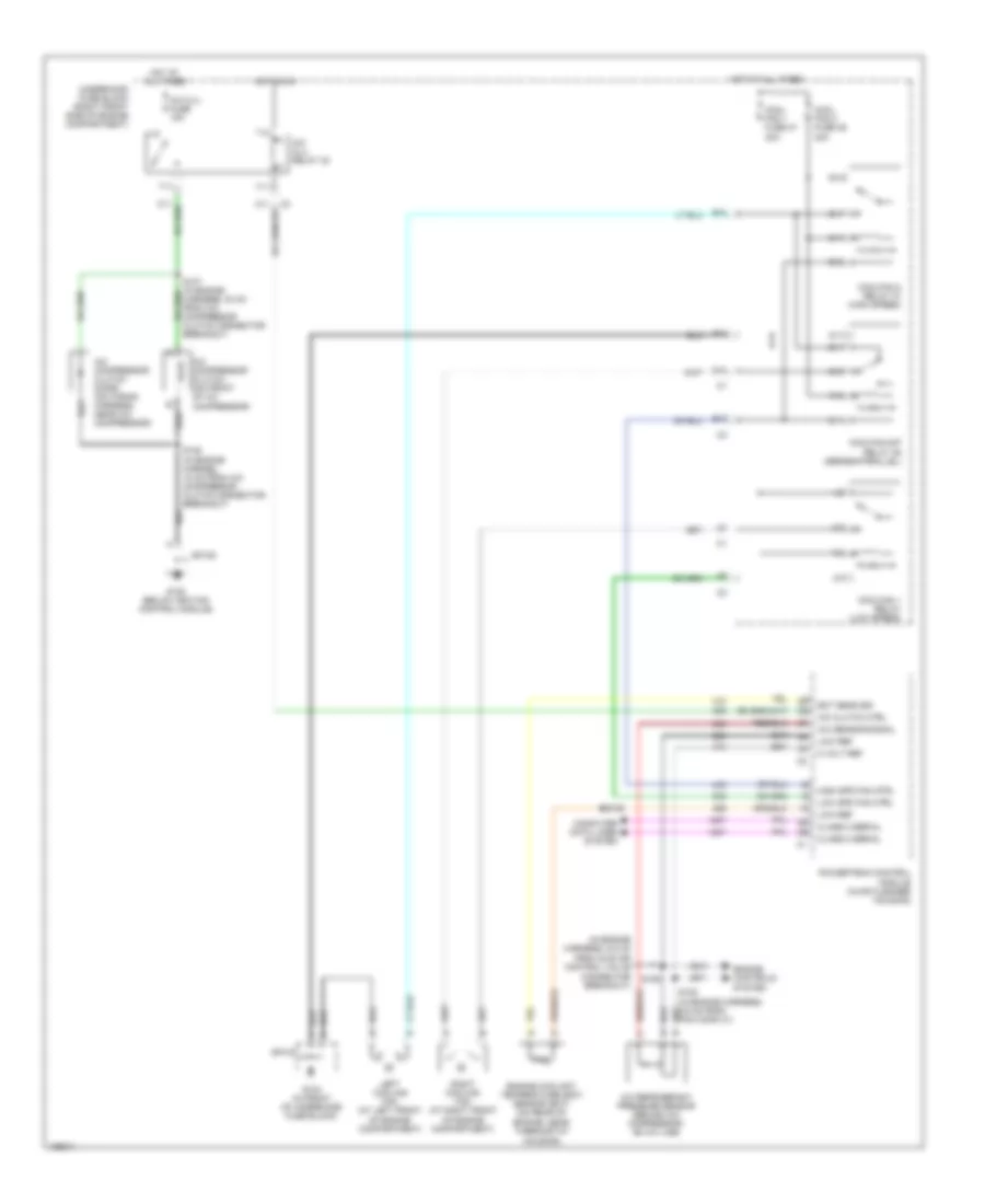
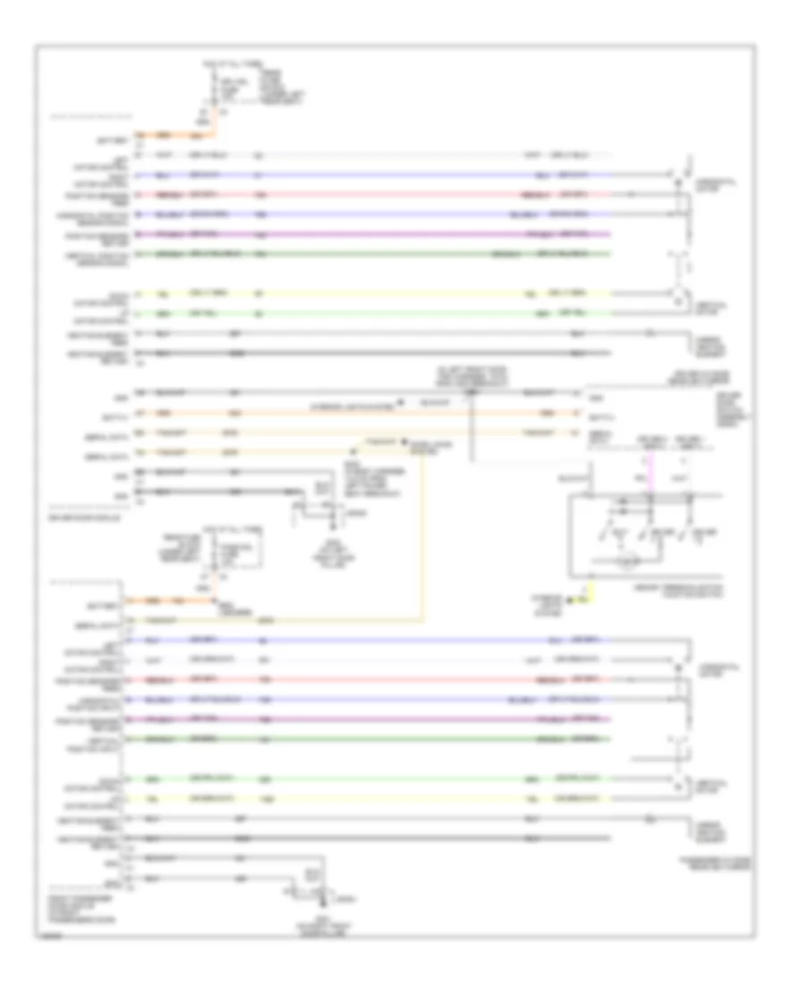
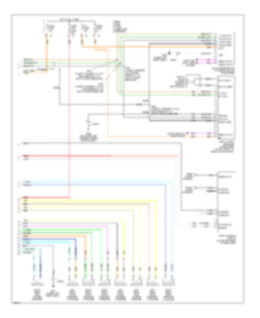
Manual A/C Wiring Diagram (1 of 2) for Pontiac Bonneville SE 2004
List of elements for Manual A/C Wiring Diagram (1 of 2) for Pontiac Bonneville SE 2004:
- (in hvac harness, 30 cm from c204 breakout) s221
- (in i/p harness, 6.5 cm from ipm breakout) s203
- (not used)
- 5v ref
- A10
- A11
- A12
- A13
- A14
- A15
- A16
- Air temperature actuator (behind dash, at left front side of blower motor)
- Amb lgt sens sig
- Anti-lock brakes system
- B10
- B11
- B12
- B13
- B14
- B15
- B16
- Bat pos voltage
- Battery
- Blower motor (under right side of dash, above sound insulator)
- Blower motor control processor (mounted on right front of blower motor)
- Blwr mtr gnd
- Blwr sp cntrl
- Blwr sp input
- Blwr volt
- C1 a10
- Class 2 data
- Computer data lines system
- Crtsy lamp sw out
- D12
- Dimmer sw sig
- Fog lp switch
- G200 (on left front door pillar)
- G201 (on right front door pillar)
- Gnd
- Grd
- Headlights system
- Hot at all times
- Hot in on
- Hvac batt fuse 37 10a
- Hvac blo fuse 2 30a
- Hvac control module (located in center of dash)
- Hvac fuse 33 10a
- Ign 3 voltage
- Interior lights system
- Key cyl lp ctrl
- Key in ign sw
- Lamps ctrl
- Lft temp dr ctrl
- Low ref
- Mode actuator (under left side of dash, on left side of hvac assembly)
- Mode dr ctrl
- Rear fuse block (under left rear seat)
- Recirc dr ctrl
- Recirculation actuator (under right side of dash, to right of blower motor)
- S222 (in hvac harness, 23.5 cm from c204 breakout)
- S253 (in i/p harness, 13 cm from turn signal hazard flasher module)
- Solid state
- Sp200
- Sp201
- Speed cntl
- Trac cntrl sw
- Trunk release sw
- Trunk, tailgate, fuel doors system
- Twilight sentinel
- Warning system
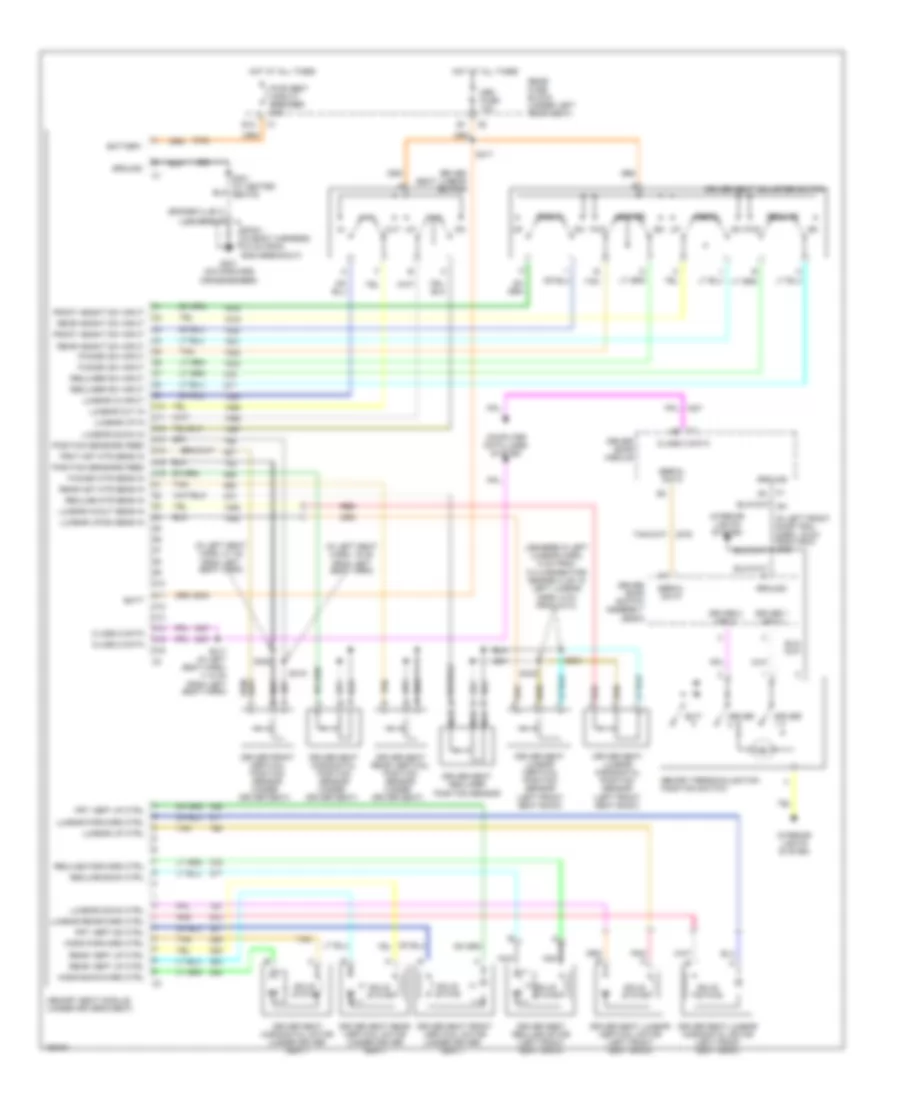
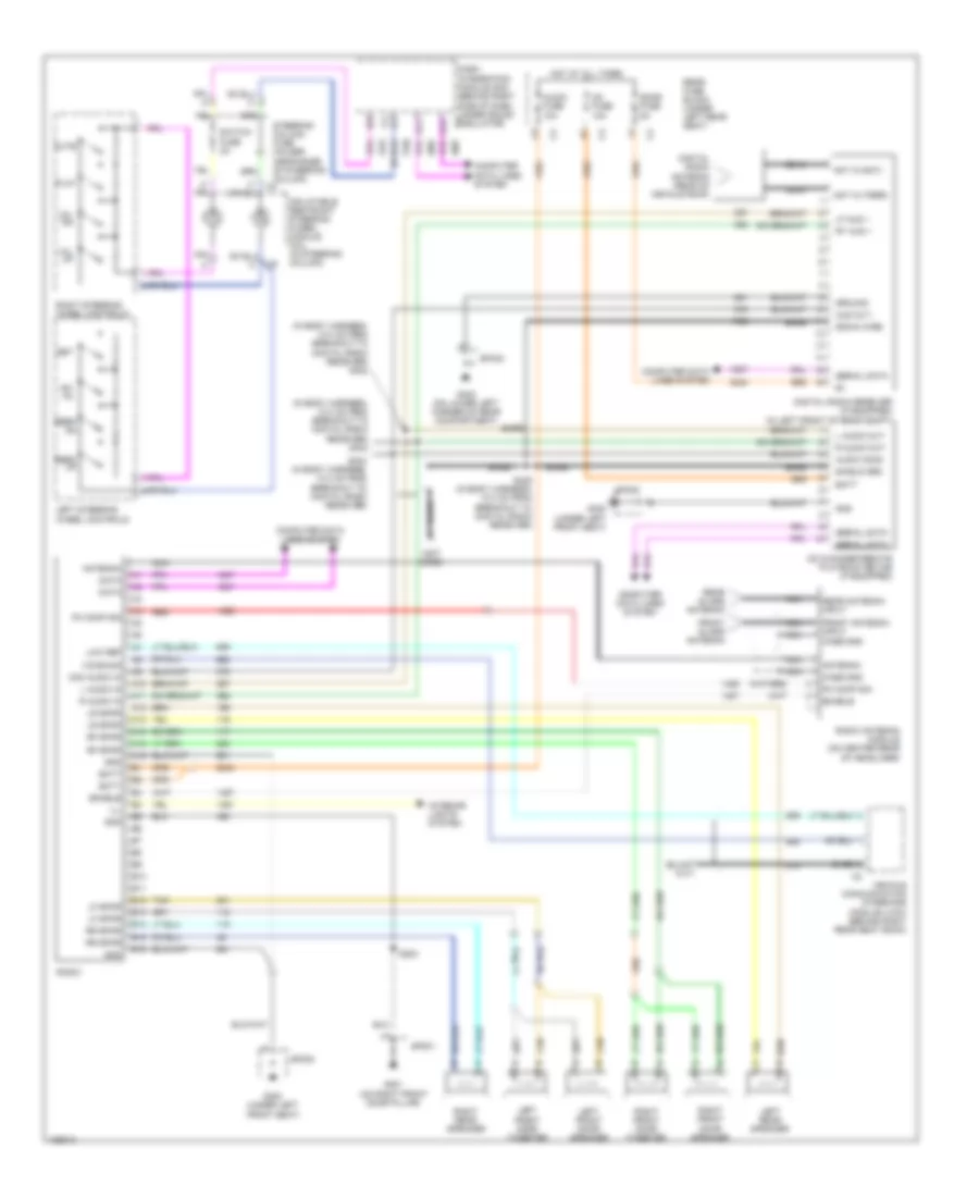
Manual A/C Wiring Diagram (2 of 2) for Pontiac Bonneville SE 2004
List of elements for Manual A/C Wiring Diagram (2 of 2) for Pontiac Bonneville SE 2004:
- (in engine harness, 6.5 cm
- 5 volt ref
- A/c clu fuse 15a
- A/c clu relay 32
- A/c clutch ctrl
- A/c compressor clutch (on front of a/c compressor)
- A/c compressor clutch diode (on wiring harness, near a/c compressor)
- A/c refrigerant pressure sensor (behind a/c compressor, on a/c line)
- A/c sensor signal
- A10
- A11
- B10
- B11
- C10
- C11
- Class 2 serial
- Computer data lines system
- Cool fan 1 fuse 47 30a
- Cool fan 2 fuse 46 30a
- Coolfan 1 relay (low speed)
- Coolfan 2 relay 37 (high speed)
- Coolfan s/p relay 39 (series/parallel)
- D10
- E10
- E11
- Ect sens sig
- Engine controls system
- Engine coolant temperature (ect) sensor (ect) (on rear of
- Engine, near thermostat housing)
- F11
- From idle air control valve connector breakout)
- G10
- G103 (in front of underhood fuse block)
- G105 (below ignition control module)
- G11
- High spd fan ctrl
- Hot at all times
- Hot in on
- Left cooling fan (at left front of engine compartment)
- Low ref
- Low spd fan ctrl
- Powertrain control module (in air cleaner housing)
- Right cooling fan (at right front of engine compartment)
- S106
- S108 (in engine harnes, 18 cm from a/c compressor clutch connector breakout)
- S109
- Sp103
- Sp105
- T10
- T11
- Underhood fuse block (right front side of engine compartment)
- V10
- V11
3.8L VIN K
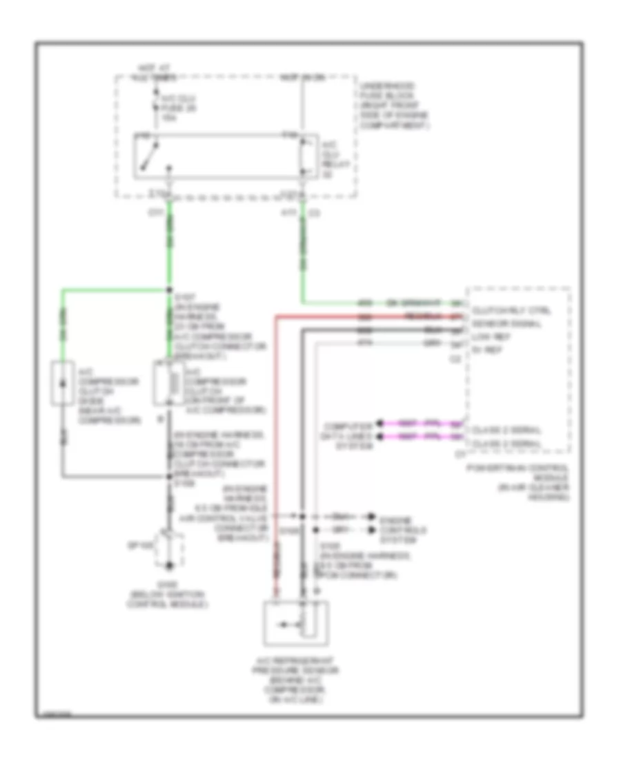
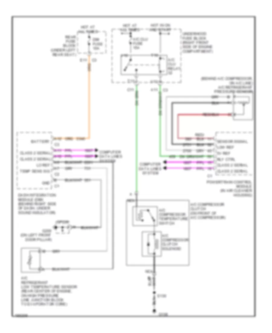
3.8L VIN K, Compressor Wiring Diagram for Pontiac Bonneville SE 2004
List of elements for 3.8L VIN K, Compressor Wiring Diagram for Pontiac Bonneville SE 2004:
- (in engine harness, 18 cm from a/c compressor clutch connector breakout) s108
- (in engine harness, 6.5 cm from idle air control valve connector breakout)
- 5v ref
- A/c clu fuse 26 15a
- A/c clu relay
- A/c compressor clutch (on front of a/c compressor)
- A/c compressor clutch diode (near a/c compressor)
- A/c refrigerant pressure sensor (behind a/c compressor, on a/c line)
- Class 2 serial
- Clutch rly ctrl
- Computer data lines system
- Engine controls system
- G105 (below ignition control module)
- Hot at all times
- Hot in on
- Low ref
- Powertrain control module (in air cleaner housing)
- S106
- Sensor signal
- Sp105
- T10
- T11
- Underhood fuse block (right front side of engine compartment)
- V10
- V11
4.6L VIN A
4.6L VIN A, Compressor Wiring Diagram for Pontiac Bonneville SE 2004
List of elements for 4.6L VIN A, Compressor Wiring Diagram for Pontiac Bonneville SE 2004:
- (behind a/c compressor, on a/c line) a/c refrigerant pressure sensor
- 5v ref
- A/c clu fuse 15a
- A/c clu relay
- A/c compressor clutch (on front of a/c compressor)
- A/c compressor clutch solenoid
- A/c compressor temperature switch
- A/c refrigerant low temperature sensor (rear center of engine, on high pressure line junction block to evaporator core)
- A11 class 2 serial
- A12
- A12 class 2 serial
- Battery
- C3 e11
- Class 2 serial
- Computer data lines system
- Dash integration module (dim) (behind right side of dash, under sound insulator)
- Dim fuse 10a
- G108
- G200 (on left front door pillar)
- Gnd
- Hot at all times
- Hot in on and start
- Lo ref
- Low ref
- Nca
- Powertrain control module (in air cleaner housing)
- Rear fuse block (under left rear seat)
- Rly ctrl
- S130
- Sensor signal
- Sp200
- T10
- T11
- Temp sens sig
- Underhood fuse block (right front side of engine compartment)
- V10
- V11
ANTI-LOCK BRAKES
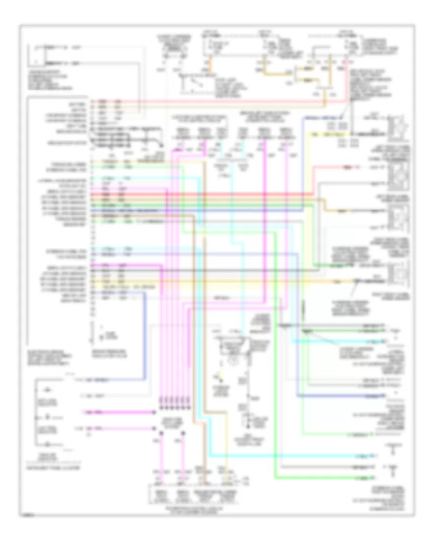
Anti-lock Brakes Wiring Diagram for Pontiac Bonneville SE 2004
List of elements for Anti-lock Brakes Wiring Diagram for Pontiac Bonneville SE 2004:
- (3.8l)
- (4.6l)
- (4.6l) (3.8l)
- (behind left side of dash) instrument panel integration module
- (in body harness, 18 cm from g300 breakout)
- (in body harness, 31.5 cm from g300 breakout)
- (in body harness, 8.5 cm from g300 breakout) sp304
- (in engine harness, 12.5 cm from right front wheel speed sensor breakout) s101
- (in engine harness, 19 cm from right front wheel speed sensor breakout)
- (located in center of dash) hvac control module
- (or 830)
- (splice s103: 49 cm from left front wheel speed sensor breakout) (splice s104: 42.5 cm from left front wheel speed sensor breakout)
- 3.8l
- 3.8l
- 4.6l
- 4.6l
- 830 (or 873)
- A1 c2
- Abs fuse 10a
- Abs fuse 50a
- Abs ind lamp
- Anti-lock indicator
- Auto a/c
- B (or tan)
- B c4
- Battery
- Brake pressure modulator valve
- C1 a
- C1 c8
- C11
- C12 c1
- C3 f1
- Computer data lines system
- Delivered torque output
- Electronic brake control module (ebcm) (on left front of engine compartment)
- G104 (on top of transmission)
- G110
- G201 (on right front door pillar)
- Ground-module
- Ground-pump motor
- Hot at all times
- Hot in run
- Ignition
- Instrument panel cluster
- Interior lights system
- Lateral acceleration sensor (w/ active brake control) (under left rear seat)
- Lateral accelerometer
- Left front wheel speed sensor (wss) (on left front wheel hub assembly)
- Left rear wheel speed sensor
- Lf wheel spd sens-ret
- Lf wheel spd sens-sig
- Low trac indicator
- Lr wheel spd sens-ret
- Lr wheel spd sens-sig
- Manual a/c
- Nca
- Powertrain control module (in air cleaner housing)
- Pump motor
- Rear fuse block (under left rear seat)
- Red
- Requested torque input
- Rf wheel spd sens-ret
- Rf wheel spd sens-sig
- Right front wheel speed sensor
- Right rear wheel speed sensor (wss) (on right rear wheel hub assembly)
- Rr wheel spd sens-ret
- Rr wheel spd sens-sig
- S102
- S103
- S104
- S104 s103
- S111
- S205
- S303
- S305
- Sens feed-5v
- Sensor ret
- Serial data class 2
- Splice pack sp201
- Steering wheel pos
- Steering wheel position sensor (swps) (w/ active brake control) (on base of steering column)
- Stop lamp/ a/t shift lock control switch (lower left side of dash)
- Stop lp fuse 15a
- Stoplight sw
- Tan
- Torque delivered
- Torque desired
- Trac ctrl sw
- Trac off indicator
- Traction control switch
- Traction ready ind
- Underhood fuse block (right front side of engine compt)
- Var effort steering
- Variable effort steering actuator (if equipped) (on left side of power steering gear)
- Vent tube
- Yaw rate sens
- Yaw rate sensor (w/ active brake control) (under rear shelf, behind lid hinge)
ANTI-THEFT
Forced Entry Wiring Diagram for Pontiac Bonneville SE 2004
List of elements for Forced Entry Wiring Diagram for Pontiac Bonneville SE 2004:
- A11
- A12
- B12
- Class 2
- Class 2 data line
- Computer
- Computer data lines system
- Dash integration module (dim) (behind right side of dash, under sound insulator)
- Data
- Data lines
- Door open input
- Driver door lock actuator
- Driver door module (ddm)
- Drv mdl fuse 7 10a
- Exterior lights system & headlights system
- Front passenger door lock actuator
- Front passenger door module (fpdm) (in front passenger's door)
- Ground
- Horn ctrl
- Horns system
- Hot at all times
- Key switch
- Left rear door lock actuator (in left rear door)
- Left rear door module (lrdm)
- Lf door ajar in
- Lf door open in
- Lights ctrl
- Open
- Pass mdl fuse 25 10a
- Pwr door serial data
- Rear fuse block (under left rear seat)
- Rear integration module (rim) (behind back seat cushion)
- Rf door open input
- Right rear door lock actuator
- Right rear door module (rrdm) (in right rear door)
- Rrdr mdl fuse 18 10a
- S302 (in body harness, 14.5 cm from left power seat breakout)
- Serial
- Serial data class 2
- System
- Tan
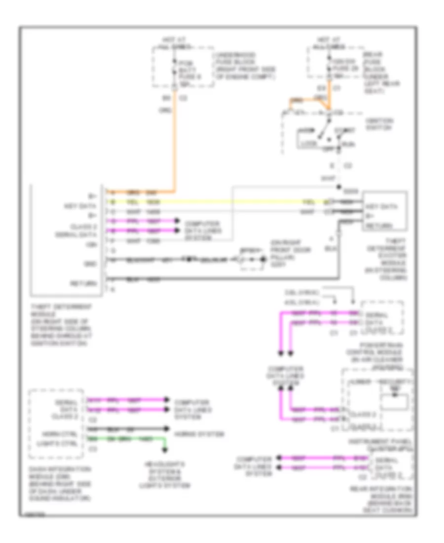
Pass-Key Wiring Diagram for Pontiac Bonneville SE 2004
List of elements for Pass-Key Wiring Diagram for Pontiac Bonneville SE 2004:
- (on right front door pillar) g201
- 3.8l (vin k)
- 4.6l (vin a)
- A11
- A12
- Acc
- B12
- Class 2
- Computer data lines system
- Dash integration module (dim) (behind right side of dash, under sound insulator)
- E9 c1
- Gnd
- Headlights system & exterior lights system
- Horn ctrl
- Horns system
- Hot at all times
- Ign
- Ign sw fuse 29 15a
- Ignition switch
- Instrument panel cluster (ipc)
- Key data
- Lights ctrl
- Lock
- Logic
- Nca
- Off
- Pcm batt fuse 8 10a
- Powertrain control module (in air cleaner housing)
- Rear fuse block (under left rear seat)
- Rear integration module (rim) (behind back seat cushion)
- Return
- Run
- S205
- S208
- Security ind
- Serial data
- Serial data class 2
- Sp201
- Start
- Theft deterrent exciter module (in steering column)
- Theft deterrent module (on right side of steering column, behind shroud at ignition switch)
- Underhood fuse block (right front side of engine compt)
BODY CONTROL MODULES
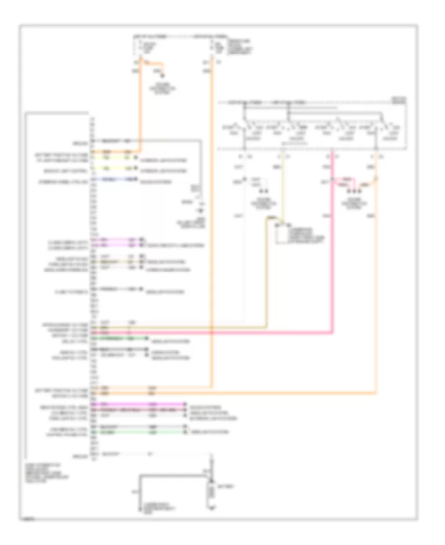
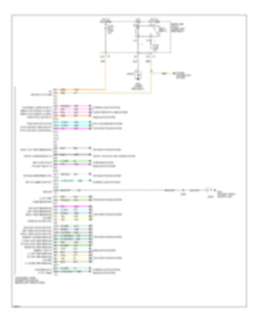
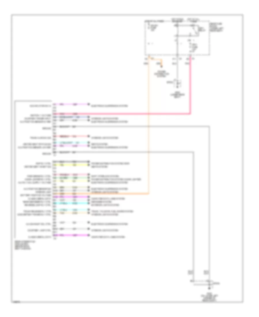
Dash Integration Module Wiring Diagram for Pontiac Bonneville SE 2004
List of elements for Dash Integration Module Wiring Diagram for Pontiac Bonneville SE 2004:
- (or 1485)
- (under right side rear seat) g305
- A10
- A11
- A12
- Acc
- Accessory voltage
- B10
- B11
- B12
- Backup light control
- Battery
- Battery positive voltage
- Class 2 serial data
- Computer data lines system
- Control power ctrl
- Dash integration module (dim) (behind right side of dash, under sound insulator)
- Dim fuse 10a
- Drl rly ctrl
- E11
- Exterior lights system
- Flash to pass in
- Fog lamp rly ctrl
- G200 (on left front door pillar)
- Ground
- Headlamp on sig
- Headlamps/wipers sig
- Headlights system
- High beam rly ctrl
- Horn rly ctrl
- Horns system
- Hot at all times
- I/p lamp fuse sup voltage
- Ign sw fuse 15a
- Ignition 1 voltage
- Ignition 3 voltage
- Ignition switch
- Interior lights system
- Lock
- Low beam rly ctrl
- Off/run/crank voltage
- Park lamp rly ctrl
- Parklamp sw on sig
- Pnk
- Power distribution system
- Rear fuse block (under left rear seat)
- Remote radio ctrl head
- Run
- S208
- S311
- Sound systems
- Sp200
- Start
- Steering wheel ctrl sig
- Underhood fuse block (right front side of engine compt)
- Unlock
- Wiper/washer system
Instrument Panel Integration Module Wiring Diagram for Pontiac Bonneville SE 2004
List of elements for Instrument Panel Integration Module Wiring Diagram for Pontiac Bonneville SE 2004:
- 5 volt feed
- 5 volt ref
- A10
- A11
- A12
- Air conditioning system
- Air inlet actuator ctrl
- Air inlet sensor sig
- Ambient airtemp sens sig
- Ambient light in
- Anti-lock brakes system
- B10
- B11
- B12
- C10
- C11
- C12
- C13
- C14
- C15
- C16
- Computer data lines system
- Courtesy lamps on sw in
- D10
- D11
- D12
- D13
- D14
- D15
- D16
- F11
- F12
- Front fog lamp sw in
- G201 (on right front door pillar)
- G302 (under rear seat)
- Ground
- H11
- H12
- Headlights system
- Hot at all times
- Hot in on
- Hvac batt fuse 10a
- Hvac control module data
- Hvac fuse 10a
- Hvav control clock signal
- Ign-3 relay
- Ignition 3 voltage
- Inside air temp sens sig
- Instrument panel integration module (behind left side of dash)
- Interior lights system
- Ip dimmer sw in
- Key cylinder lamp out
- Key in ignition in
- Left temp actuator ctrl
- Left temp sensor sig
- Low ref
- Lt lower temp sens sig
- Lt sun load temp sens sig
- Lt upp temp sens sig
- Mode actuator ctrl
- Mode sensor sig
- Power distribution system
- Pwm blower speed ctrl
- Rear fuse block (under left rear seat)
- Right low temp sensor sig
- Right temp actuator ctrl
- Right temp sensor sig
- Rt sun load temp sens sig
- Rt upp temp sens sig
- S205
- Serial data signal class 2
- Sp201
- Sp302
- Tan
- Traction ctrl sw sig
- Trunk lid release sw in
- Trunk, tailgate, fuel doors system
- Twilight delay in
- Warnings system
Rear Integration Module Wiring Diagram for Pontiac Bonneville SE 2004
List of elements for Rear Integration Module Wiring Diagram for Pontiac Bonneville SE 2004:
- A10
- A11
- A12
- Acc inflator sw in
- Alc exhaust sol ctrl
- Alc position sensor 5v ref
- Alc position sensor low ref
- Alc position sensor sig
- B10
- B11
- B12
- B4 trunk release rly ctrl
- Battery positive voltage
- Cigar lighter rly ctrl
- Class 2 serial data
- Computer data lines system
- Courtesy lamp ctrl
- Courtesy power input
- Defogger system
- Electronic suspension system
- Exterior lights system
- G302 (under rear seat)
- G402 (on lower left corner of rear compt)
- Ground
- Heated seat inhibit sig
- Heated seat status sig
- Hot at all times
- Hot in run or start
- Ign sw fuse 15a
- Ign-1 fuse 10a
- Ign-1 relay
- Ignition 1 voltage
- Inadvertent power rly ctrl
- Interior lamp
- Interior lights system
- Park brake rly ctrl
- Pnk
- Power distribution system
- Power distribution system (cigar lighter)
- Power distribution system (rap)
- Rap rly ctrl
- Rear defogger rly ctrl
- Rear fuse block (under left rear seat)
- Rear integration module (rim) (behind back seat cushion)
- Reverse lamp rly ctrl
- Seats system
- Shift interlock system
- Sp302
- Sp402
- Tan
- Trunk ajar sw sig
- Trunk, tailgate, fuel doors system
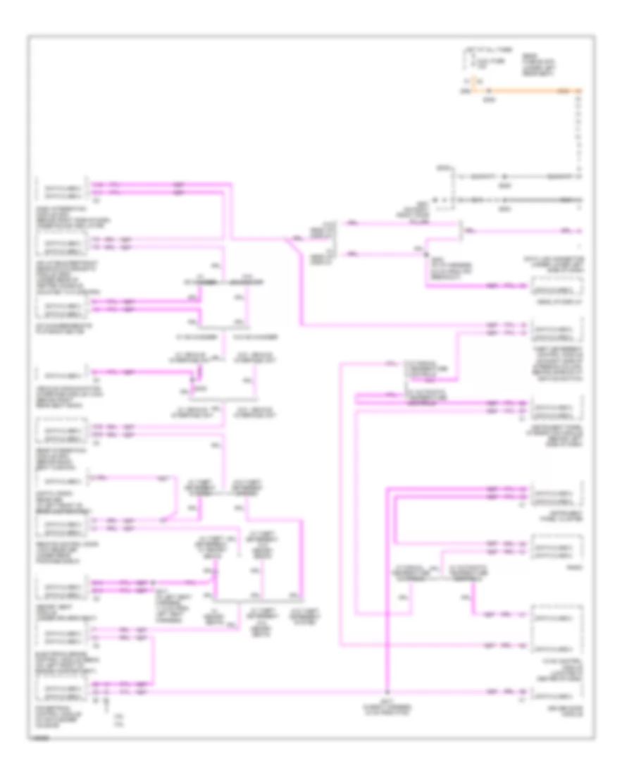
COMPUTER DATA LINES
Computer Data Lines Wiring Diagram for Pontiac Bonneville SE 2004
List of elements for Computer Data Lines Wiring Diagram for Pontiac Bonneville SE 2004:
- 3.8l
- 4.6l
- A11
- A12
- Aldl fuse 10a
- B12
- Cd changer-remote playback device
- D14
- D15
- Dash integration module (dim) (behind right side of dash, under sound insulator)
- Data class 2
- Data link connector (under lower left side of dash)
- Digital radio receiver (in left front of rear compartment)
- Driver door module
- Electronic brake control module (ebcm) (on left front of engine compartment)
- G201 (on right front door pillar)
- Head up display
- Hot at all times
- Hvac control module (located in center of dash)
- Inflatable restraint sensing & diagnostic module (sdm) (under rear of center console, mounted to floor pan)
- Instrument panel cluster
- Instrument panel integration module (behind left side of dash)
- Memory seat module (under driver's seat)
- Powertrain control module (in air cleaner housing)
- Radio
- Rear fuse block (under left rear seat)
- Rear integration module (rim) (behind back seat cushion)
- Remote control door lock receiver (under rear package shelf)
- S202 (in i/p harness, 6.5 cm from ipm breakout)
- S203
- S205
- S217 (in body harness, 24 cm from p100)
- S308
- S317 (in left seat harness, 11.5 cm from left seat harness)
- Sp201
- Theft deterrent control module (on right side of steering column, behind shroud at ignition switch)
- Vehicle communication interface module (vcim) (behind right rear seat back)
- W/ automatic temperature controls
- W/ cd changer
- W/ head up display
- W/ manual temperature controls
- W/ memory seats
- W/ theft deterrent system
- W/ theft deterrent,
- W/ theft deterrent, w/ memory seats
- W/ theft deterrent, w/o memory seats
- W/ vehicle interface unit
- W/o vehicle interface unit
- W/o cd changer
- W/o head up display
- W/o memory seats
- W/o theft deterrent system
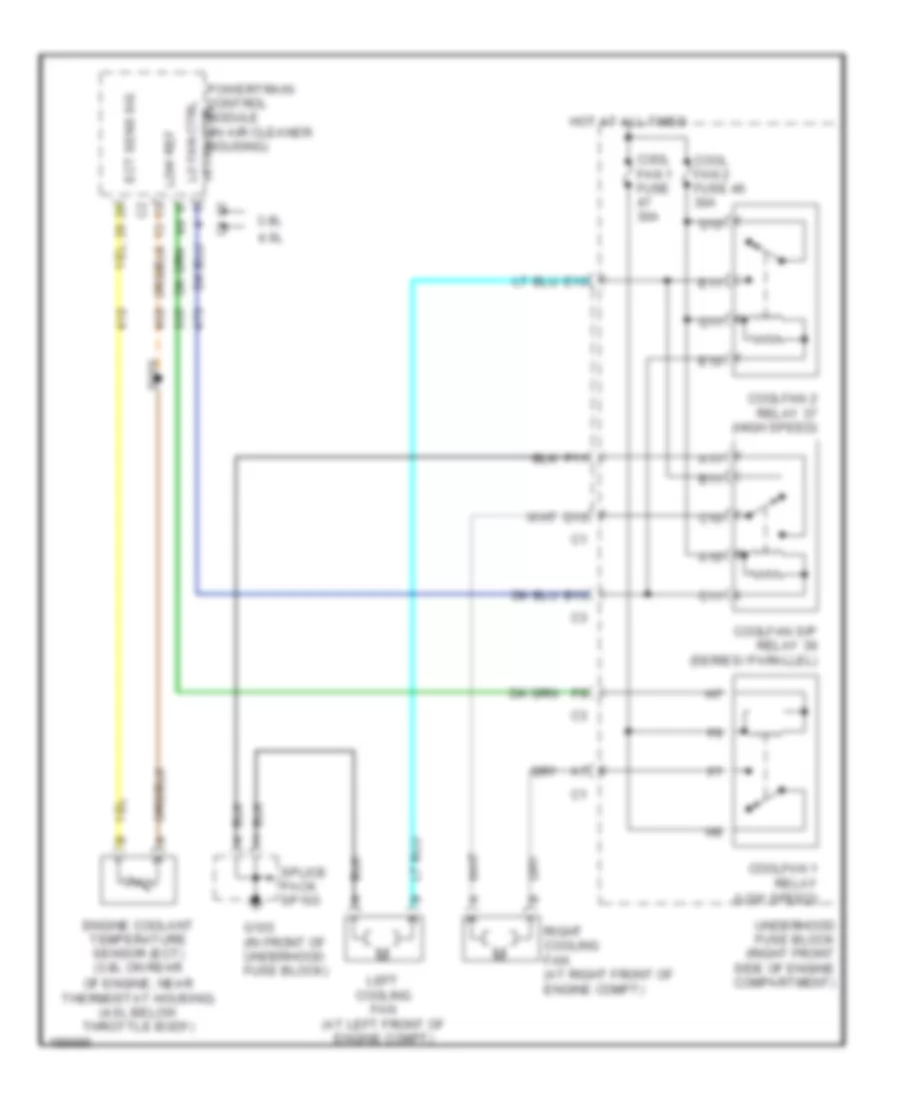
COOLING FAN
Cooling Fan Wiring Diagram for Pontiac Bonneville SE 2004
List of elements for Cooling Fan Wiring Diagram for Pontiac Bonneville SE 2004:
- 3.8l
- 4.6l
- A10
- A11
- B10
- B11
- C10
- C11
- Cool fan 1 fuse 30a
- Cool fan 2 fuse 46 30a
- Coolfan 1 relay (low speed)
- Coolfan 2 relay 37 (high speed)
- Coolfan s/p relay 39 (series/ parallel)
- D10
- E10
- E11
- Ect sens sig
- Engine coolant temperature sensor (ect) (3.8l on rear
- F11
- G10
- G103 (in front of underhood fuse block)
- G11
- Hot at all times
- Left cooling fan (at left front of engine compt)
- Lo fan ctrl
- Low ref
- Of engine, near thermostat housing) (4.6l below throttle body)
- Powertrain control hi fan ctrl module (in air cleaner housing)
- Right cooling fan (at right front of engine compt)
- S109
- Splice pack sp103
- Underhood fuse block (right front side of engine compartment)
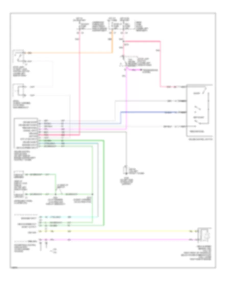
CRUISE CONTROL
Cruise Control Wiring Diagram for Pontiac Bonneville SE 2004
List of elements for Cruise Control Wiring Diagram for Pontiac Bonneville SE 2004:
- 3.8l
- 4.6l
- All times
- Cancel input
- Cr cont fuse 10a
- Cruise control module (ccm) (on left side of engine compartment, on strut tower)
- Cruise control switch
- Cruise inhibit
- Cruise on/off
- Cruise set/coast
- Engage ouput
- Engaged input
- G106 (on left side of radiator support)
- Ground
- Head up display (hud) module (on top left side of dash)
- Hot at
- Hot in on or start
- Ign 1 fuse 10a
- Ignition
- Inhibit output
- Instrument panel cluster (ipc)
- Nca
- On/off
- Pnk
- Powertrain control module (pcm) (in air cleaner housing)
- Rear fuse block (under left rear seat)
- Resume/accel
- S201 (in i/p harness, 10 cm from hud display breakout)
- S215 (in body harness, 19.5 cm from p100)
- S216
- Set/coast
- Sp106 (on left strut tower)
- Sp304 (in body harness, 8.5 cm from g300 breakout)
- Stop lamp switch (lower left side of dash)
- Stop lamp/ at shift lock control switch (lower left side of dash)
- Stop lp fuse 15a
- Stp lp sig input
- Tcc/ cruise release switch
- Transmissions system
- Underhood fuse block (right front side of engine compartment)
- Vehicle spd sig
- Vehicle speed input
- Vehicle speed out
- Vehicle speed sensor (vss) (3.8l): on right front of transaxle, below power steering pump) (4.6l): lower right side of engine)
- Vss high
- Vss low
- W/ head up display
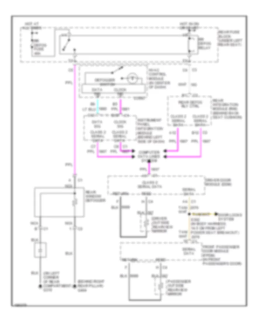
DEFOGGERS
Defoggers Wiring Diagram for Pontiac Bonneville SE 2004
List of elements for Defoggers Wiring Diagram for Pontiac Bonneville SE 2004:
- (behind right rear pillar) g404
- (on left corner of rear compartment) g310
- A12
- C1 a4
- C1 c8
- C12
- C13
- C2 b12
- C4 h
- Class 2 serial data
- Clock sig
- Computer data lines system
- Data sig
- Defogger switch
- Door locks system
- Driver door module (ddm)
- Driver outside rearview mirror
- Feed
- Front passenger door module (fpdm) (in front passenger's door)
- Hot at all times
- Hot in on or start
- Hvac control module (in center of dash)
- Instrument panel integration module (behind left side of dash)
- Logic
- Nca
- Passenger outside rearview mirror
- Rear defog rly ctrl
- Rear fuse block (under left rear seat)
- Rear integration module (rim) (behind back seat cushion)
- Rear window defogger
- Return
- Rr defog fuse 40a
- Rr defog relay
- S302 (in body harness, 14.5 cm from left power seat breakout)
- Serial data
- Tan/
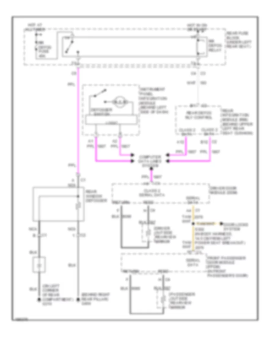
Defoggers Wiring Diagram, with Manual A/C for Pontiac Bonneville SE 2004
List of elements for Defoggers Wiring Diagram, with Manual A/C for Pontiac Bonneville SE 2004:
- (behind right rear pillar) g404
- (on left corner of rear compartment) g310
- A12
- C1 a4
- C2 b12
- C4 h
- Class 2 data
- Class 2 serial data
- Computer data lines system
- Defogger switch
- Door locks system
- Driver door module (ddm)
- Driver outside rearview mirror
- Feed
- Front passenger door module (fpdm) (in front passenger's door)
- Hot at all times
- Hot in on or start
- Instrument panel integration module (behind left side of dash)
- Logic
- Nca
- Passenger outside rearview mirror
- Rear defog rly control
- Rear fuse block (under left rear seat)
- Rear integration module (rim) (behind upper left rear seat cushion)
- Rear window defogger
- Return
- Rr defog fuse 40a
- Rr defog relay
- S302 (in body harness, 14.5 cm from left power seat breakout)
- Serial data
- Tan/
ELECTRONIC POWER STEERING
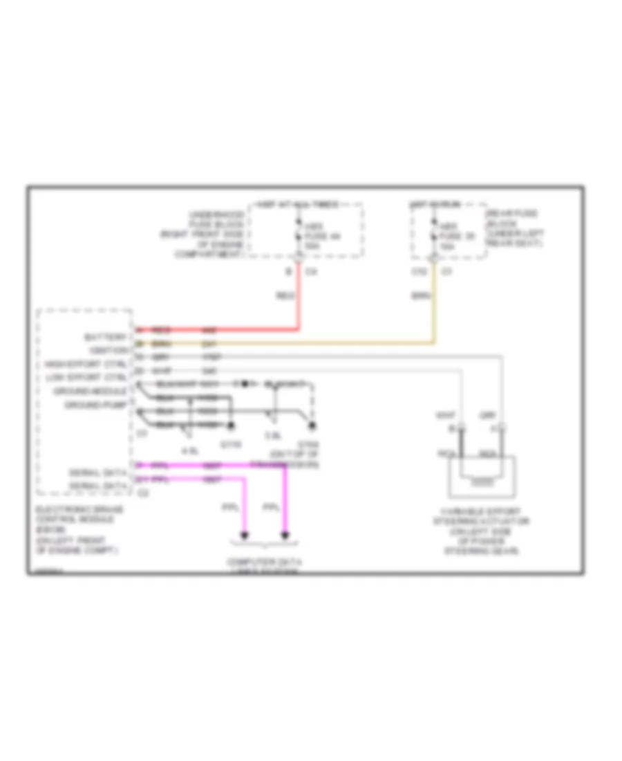
Electronic Power Steering Wiring Diagram for Pontiac Bonneville SE 2004
List of elements for Electronic Power Steering Wiring Diagram for Pontiac Bonneville SE 2004:
- (on left front of engine compt)
- 3.8l
- 4.6l
- Abs fuse 35 10a
- Abs fuse 44 50a
- Battery
- C12
- Computer data lines system
- Electronic brake control module (ebcm)
- G104 (on top of transmission)
- G110
- Ground-module
- Ground-pump
- High effort ctrl
- Hot at all times
- Hot in run
- Ignition
- Low effort ctrl
- Nca
- Rear fuse block (under left rear seat)
- Red
- S111
- Serial data
- Underhood fuse block (right front side of engine compartment)
- Variable effort steering actuator (on left side of power steering gear)
ELECTRONIC SUSPENSION
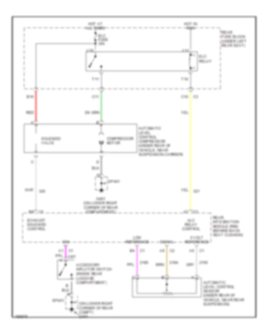
Electronic Suspension Wiring Diagram for Pontiac Bonneville SE 2004
List of elements for Electronic Suspension Wiring Diagram for Pontiac Bonneville SE 2004:
- (on lower right corner of rear compt) g401
- 5 volt reference
- Accessory inflator switch (inside rear luggage compartment)
- Alc relay control
- Automatic level control compressor (under rear of vehicle, near suspension carrier)
- Automatic level control sensor (under rear of vehicle, near rear suspension)
- B10
- C10
- C11
- Compressor motor
- Elc
- Elc fuse 30a
- Exhaust solenoid control
- G401 (on lower right corner of rear compartment)
- Hot at all times
- Hot in run
- Ign
- Low reference
- Rear fuse block (under left rear seat)
- Rear integration module (rim) (behind back seat cushion)
- Red
- Relay
- Signal
- Solenoid valve
- Sp401
- T10
- T11
- V10
- V11
ENGINE PERFORMANCE
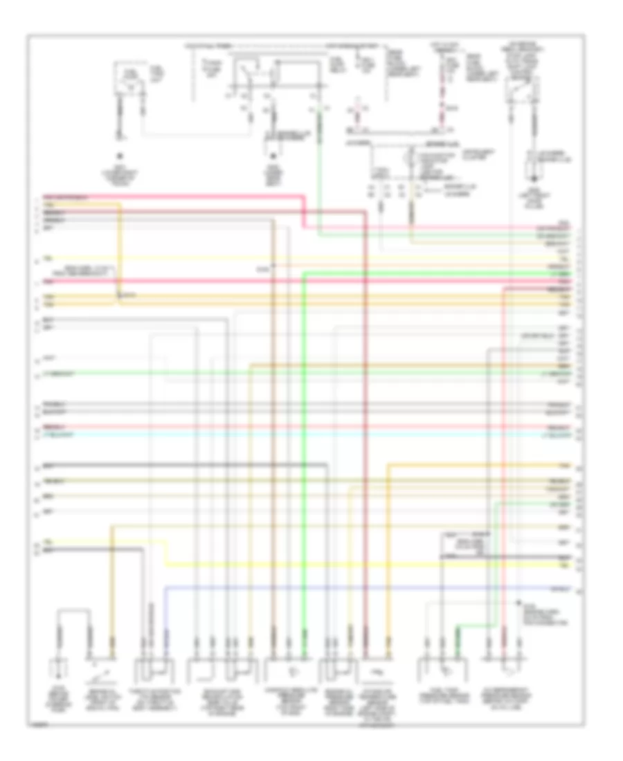
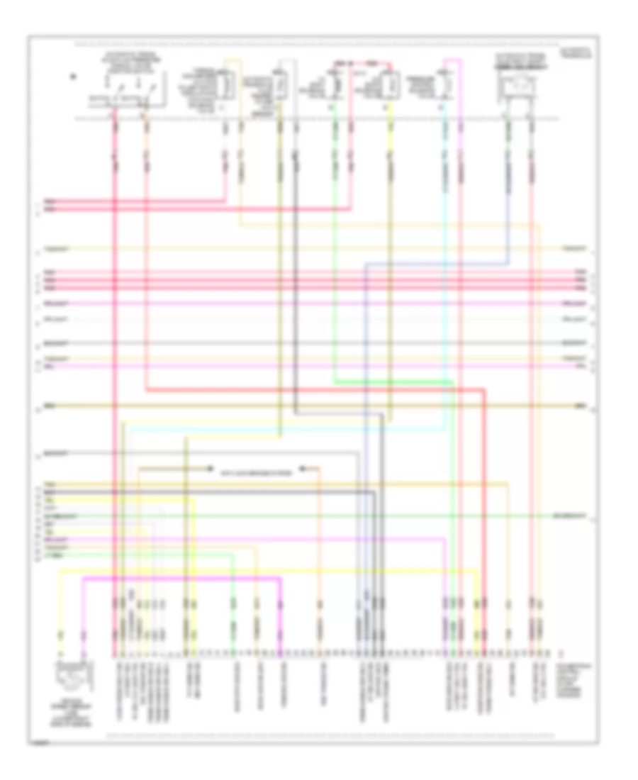
3.8L VIN K
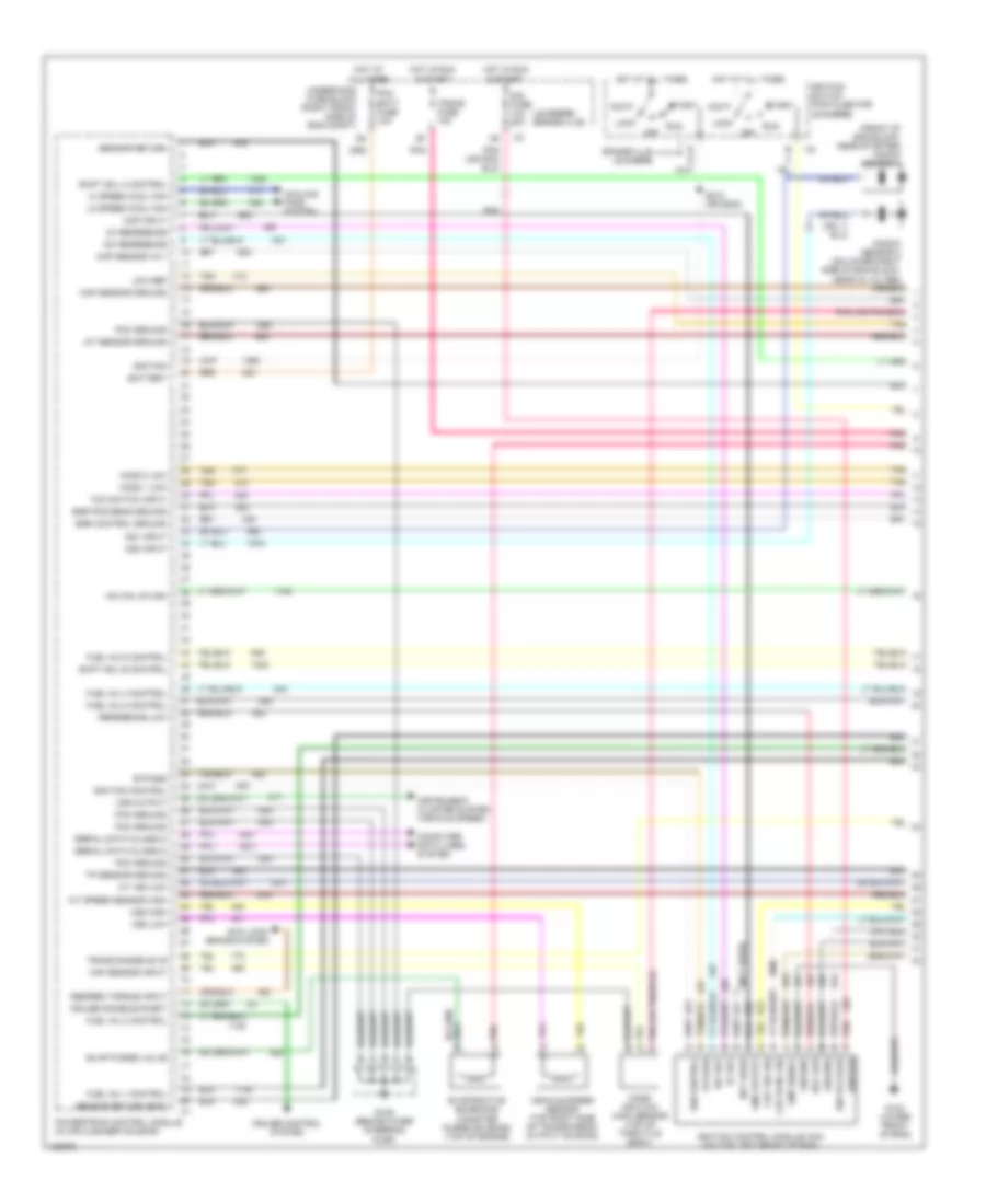
3.8L VIN K, Engine Performance Wiring Diagram (1 of 4) for Pontiac Bonneville SE 2004
List of elements for 3.8L VIN K, Engine Performance Wiring Diagram (1 of 4) for Pontiac Bonneville SE 2004:
- (front of eng block, near starter) knock sensor 1
- (le sabre) (bonneville)
- (not used)
- 18x ref
- 18x reference
- 3x ref
- 3x reference
- A/t iss low
- A/t speed sensor high
- Acc
- All times
- Anti-lock brake system
- B c
- Battery
- Bonneville le sabre
- Bypass
- Ckp 18x sig
- Ckp sync sig
- Cmp input
- Cmp output
- Cmp signal
- Computer data lines system
- Cooling fans system
- Cruise control system
- Cruise disable/inhibit
- Desired torque input
- Dis fuse 10a 20a
- E e
- Egr control ground
- Egr pos sens ground
- Evap purge valve
- Evaporative emissions canister purge solenoid (top of engine)
- Fuel inj 1 control
- Fuel inj 2 control
- Fuel inj 4 control
- Fuel inj 5 control
- Fuel inj 6 control
- G102 (lower front of eng)
- G105 (behind ower steering pump)
- Ground
- Hi speed cool fan
- Ho2s 1 low
- Ho2s 2 low
- Hot at
- Hot at all times
- Hot in run & start
- Iac coil b high
- Iat sensor ground
- Ign control
- Ign voltage
- Ignition
- Ignition control
- Ignition control module (icm) (on top left front of eng)
- Ignition switch (pigtailed for le sabre)
- Instrument cluster system (vehicle speed)
- Knock sensor 2 (on lower right side of eng block, near oil filter)
- Ks1 input
- Ks2 input
- Lo speed cool fan
- Lock
- Low ref
- Maf sensor input
- Map sensor +5 v
- Map sensor ground
- Mass air flow (maf) sensor (top of throttle body)
- Not used
- Off
- Pcm batt fuse 10a
- Pcm ground
- Pnk
- Pnk a
- Powertrain control module (in air cleaner housing)
- Ref low
- Reference low
- Run
- S212 (or s208)
- Sensor return
- Sensor return (eop)
- Serial data (class 2)
- Shift sol a control
- Shift sol b control
- Start
- Tan
- Tcc switch input
- Tp sensor ground
- Trans fuse 10a
- Trans range sw b
- Underhood fuse block (right front side of eng compt)
- Vehicle speed sensor (top right side of transmission output housing)
- Vss high
- Vss low
- Vss output
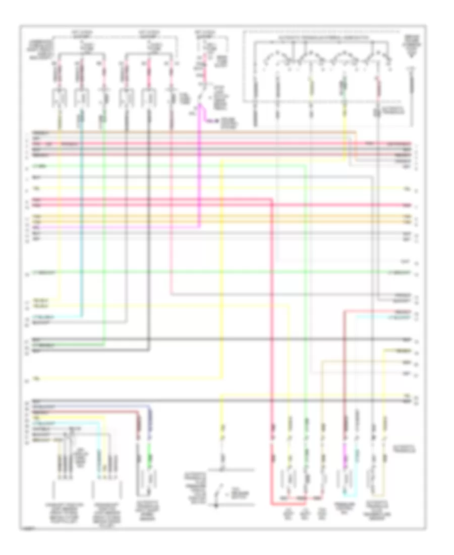
3.8L VIN K, Engine Performance Wiring Diagram (2 of 4) for Pontiac Bonneville SE 2004
List of elements for 3.8L VIN K, Engine Performance Wiring Diagram (2 of 4) for Pontiac Bonneville SE 2004:
- (behind power steering pump) g105
- (ign module harn, near icm)
- (or
- 1-2 shift sol
- 2-3 shift sol
- A6 (or pnk)
- Automatic transaxle
- Automatic transaxle fluid pressure manual valve position switch
- Automatic transaxle fluid temperature sensor
- Automatic transaxle input shaft speed sensor
- Automatic transaxle internal mode switch
- B9 (or pnk)
- Camshaft position (cmp) sensor (front of eng, behind water pump pulley)
- Crankshaft position (ckp) sensor (front of eng, behind crank pulley)
- Cruise control system
- D4 (or pnk)
- Fuel injec- tors
- Hot in run & start
- Ign 1 fuse 10a
- Injr 1 fuse 10a
- Injr 2 fuse 10a
- Pnk
- Pressure control sol
- Rear fuse block
- Red
- S135
- S136
- S216
- Stop lamp switch (near brake pedal)
- Tan
- Tcc pwm sol
- Tcc release switch
- Underhood fuse block (right front side of eng compt)
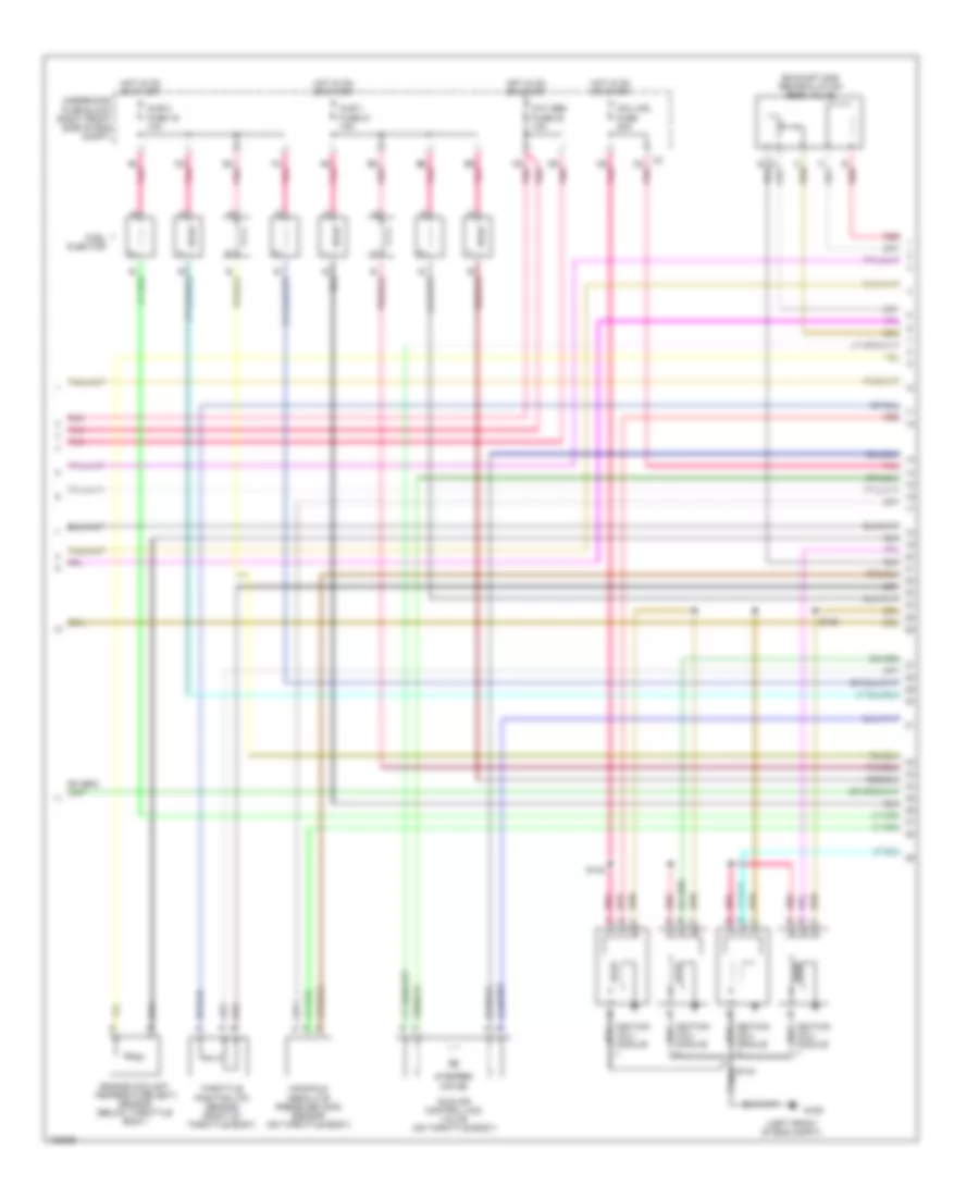
3.8L VIN K, Engine Performance Wiring Diagram (3 of 4) for Pontiac Bonneville SE 2004
List of elements for 3.8L VIN K, Engine Performance Wiring Diagram (3 of 4) for Pontiac Bonneville SE 2004:
- (bonneville)
- (bonneville) (le sabre)
- (eng harn, 10 cm from abs breakout)
- (eng harn, 6.5 cm from iac)
- (le sabre)
- (on brake pedal bracket) stop lamp/ auto trans shift lock control switch
- A/c refrigerant pressure sensor (behind a/c comp, on a/c line)
- Bonneville
- D a
- D3 pnk
- Engine oil level switch (front of eng oil pan)
- Engine oil pressure sensor (right side of engine)
- Exhaust gas recirculation (egr) valve (top right rear of engine)
- F/pmp fuse 20a
- Fuel pump
- Fuel pump relay
- Fuel tank pressure sensor (top of fuel tank)
- Fuel tank unit
- G105 (behind power steering pump)
- G200 (left front door pillar)
- G302 (under rear seat)
- G401 (lower right corner of trunk)
- Hot at all times
- Hot in acc or run
- Hot in run & start
- Ign-1 fuse 10a
- Ign1 fuse 10a
- Instrument cluster
- Intake air temperature sensor (left side of engine compt, in the air intake duct)
- Le sabre
- Malfunction indicator lamp (led for bonneville)
- Manifold absolute pressure sensor (top front of eng)
- Pnk
- Rear fuse block (under left rear seat)
- S105 (engine harn, 9.5 cm from pcm connector)
- S106
- S109
- S110
- S216
- S401
- Tach input
- Tan
- Throttle position (tp) sensor (on throttle body assembly)
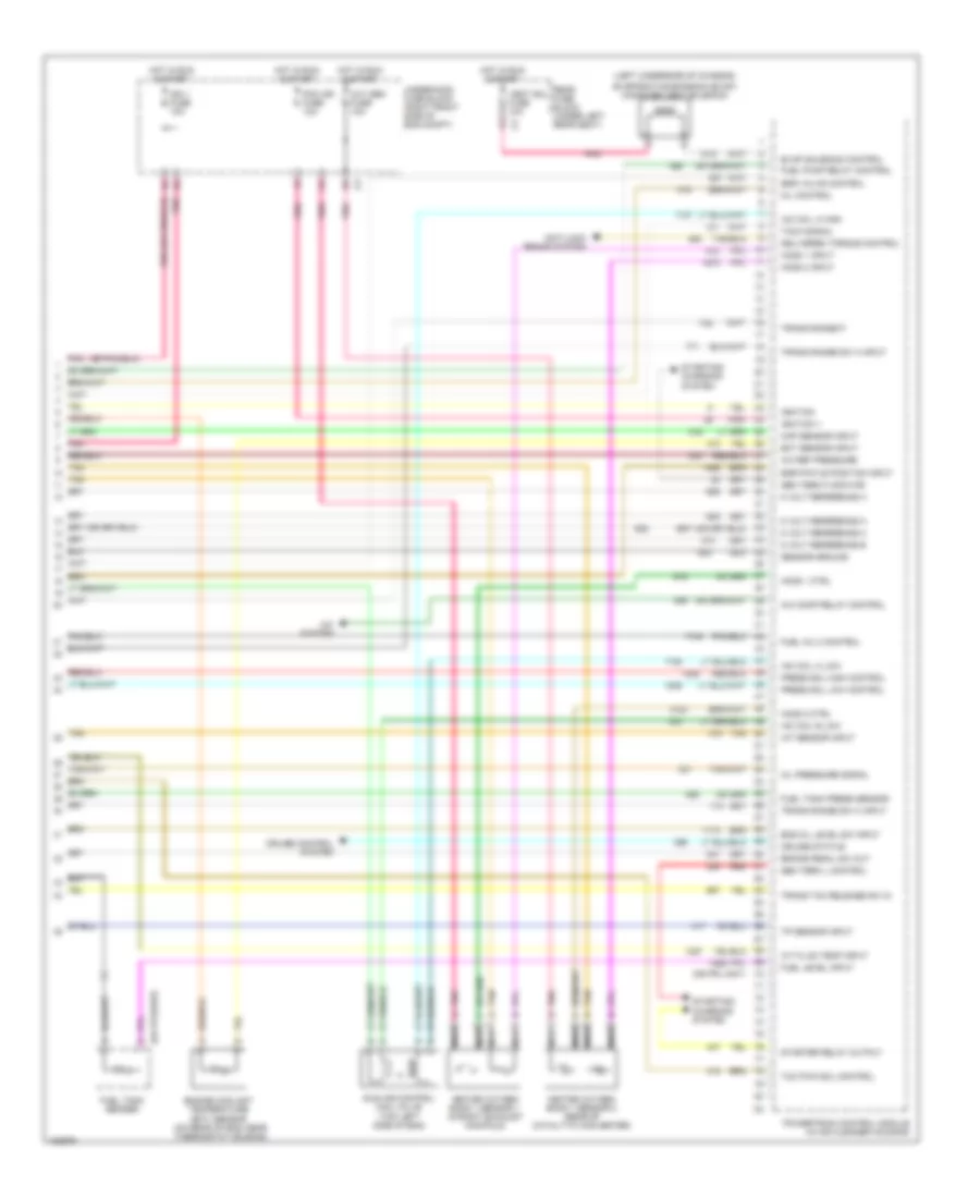
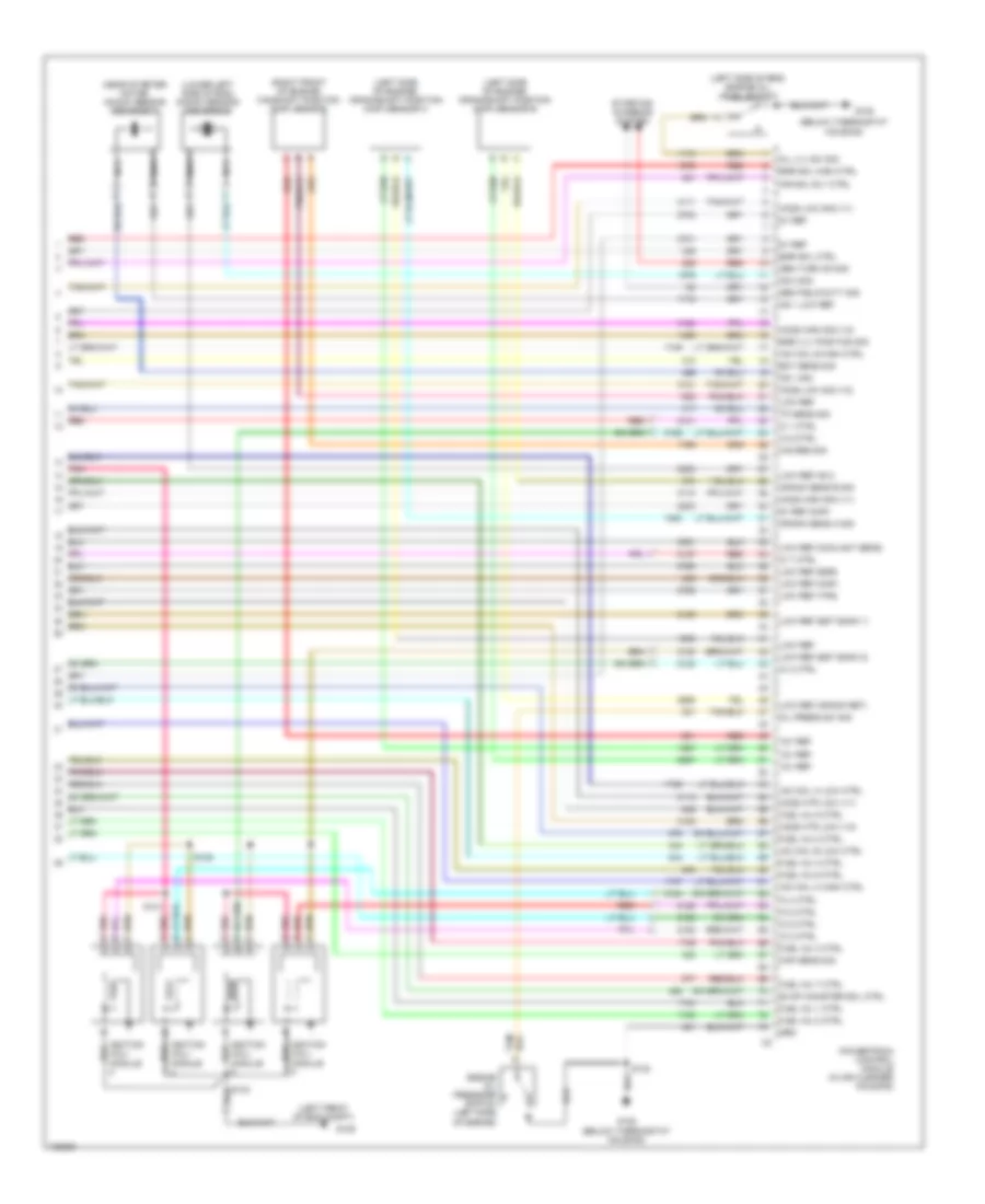
3.8L VIN K, Engine Performance Wiring Diagram (4 of 4) for Pontiac Bonneville SE 2004
List of elements for 3.8L VIN K, Engine Performance Wiring Diagram (4 of 4) for Pontiac Bonneville SE 2004:
- (left underside of chassis)
- 5 volt reference a
- 5 volt reference b
- A/c comp relay control
- A/c ref pressure
- A/c system
- A/t fluid temp input
- Anti-lock brake system
- Brake pedal sw out
- Cruise control system
- Cruise status
- Delivered torque control
- Ect sensor input
- Egr pintle position input
- Egr valve control
- Eng oil level sw input
- Engine coolant temperature (ect) sensor (on rear of eng, near thermostat housing)
- Evap solenoid control
- Evaporative emission (evap) canister vent solenoid
- Fuel inj 3 control
- Fuel level input
- Fuel pump relay control
- Fuel tank press sensor
- Fuel tank sender
- Gen term f monitor
- Gen term l control
- Heated oxygen bank 1 sensor 1 (in right exhaust manifold)
- Heated oxygen bank 1 sensor 2 (rear of catalytic converter)
- Ho2s 1 ctrl
- Ho2s 1 input
- Ho2s 2 ctrl
- Ho2s 2 input
- Hot in run & start
- Iac coil a high
- Iac coil a low
- Iac coil b low
- Iat sensor input
- Idle air control (iac) valve (top left side of eng)
- Ign 1 fuse 10a
- Ignition
- Ignition 1
- Map sensor input
- Mil control
- Nca
- Oil pressure signal
- Oxy sen fuse 10a
- Pcm ign fuse 10a
- Pnk
- Powertrain control module (in air cleaner housing)
- Press sol high control
- Press sol low control
- Rear fuse block (under left rear seat)
- Red
- Sensor ground
- Starter relay output
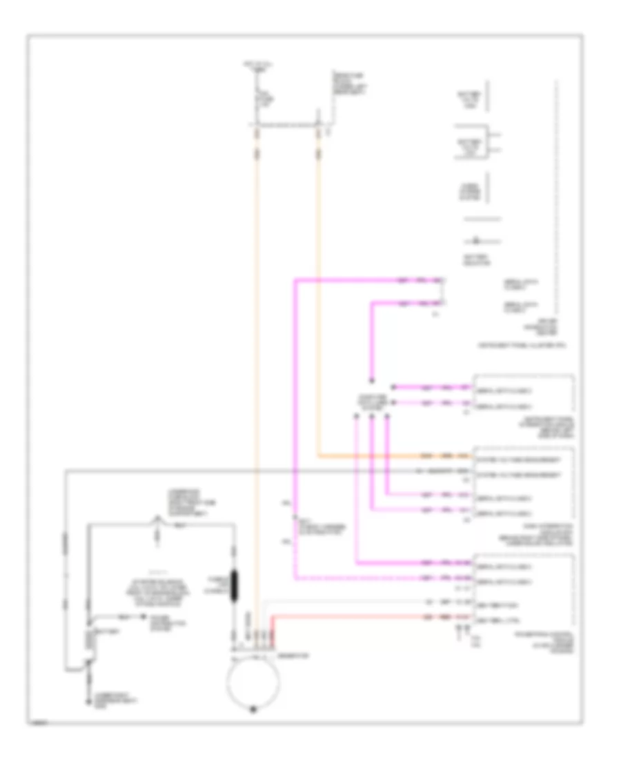
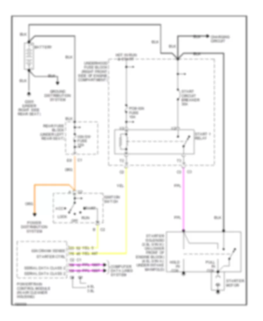
- Starting/ charging system
- Tach signal
- Tan
- Tcc pwm sol control
- Tp sensor input
- Trans range p
- Trans range sw a input
- Trans range sw c input
- Trans tcc release sw in
- Underhood fuse block (right front side of eng compt)
- Vent sol fuse 10a
4.6L VIN A
4.6L VIN A, Engine Performance Wiring Diagram (1 of 5) for Pontiac Bonneville SE 2004
List of elements for 4.6L VIN A, Engine Performance Wiring Diagram (1 of 5) for Pontiac Bonneville SE 2004:
- (in body harn, 31.5 cm from fuel tank harn breakout)
- 5v ref
- 5volt ref
- A/c clutch rly ctrl
- A/c press sens sig
- Acc
- Acc/run/crank volt
- Air conditioning system
- Air pmp rly ctrl
- Bat
- Brake sw sig
- Class 2 serial data
- Computer data lines system
- Cooling fans system
- Crank sig
- Cruise control system
- Cruise ctrl engaged
- Cruise inhibit sig
- Engine spd sig
- Evaporative emissions (evap) canister purge solenoid (left rear of engine)
- Evaporative emissions (evap) canister vent solenoid valve (left underside of vehicle chassis)
- Fuel press sens sig
- Fuel tank pressure (ftp) sensor (top of fuel tank)
- G108 (below thermo- stat housing)
- Grd
- H/s fan rly ctrl
- Hot at all times
- Hot in on or start
- Iat sensor
- Ign
- Ign 1 fuse 11 10a
- Ign 1 voltage
- Ignition switch
- Info not available
- Instrument cluster system
- Instrument panel cluster (ipc)
- L/s fan rly ctrl
- Low ref
- Malfunction indicator lamp (mil)
- Mass air flow (maf)/ intake air temperature (iat) sensor
- Mil ctrl
- Off
- Pcm batt fuse 8 10a
- Pcm ign fuse 19 10a
- Pnk
- Powertrain control module (in air cleaner housing)
- Pri fuel lvl sens sig
- Pri fuel pmp rly ctrl
- Rear fuse block (under left rear seat)
- S130
- S208
- S401
- Sens sig
- Start
- Starter rly coil ctrl
- Starting/charging system
- Tan
- Tcc brake sw
- Underhood fuse block (right front side of eng compt)
- Vent sol ctrl
- Vent sol fuse 11 10a
- Vss
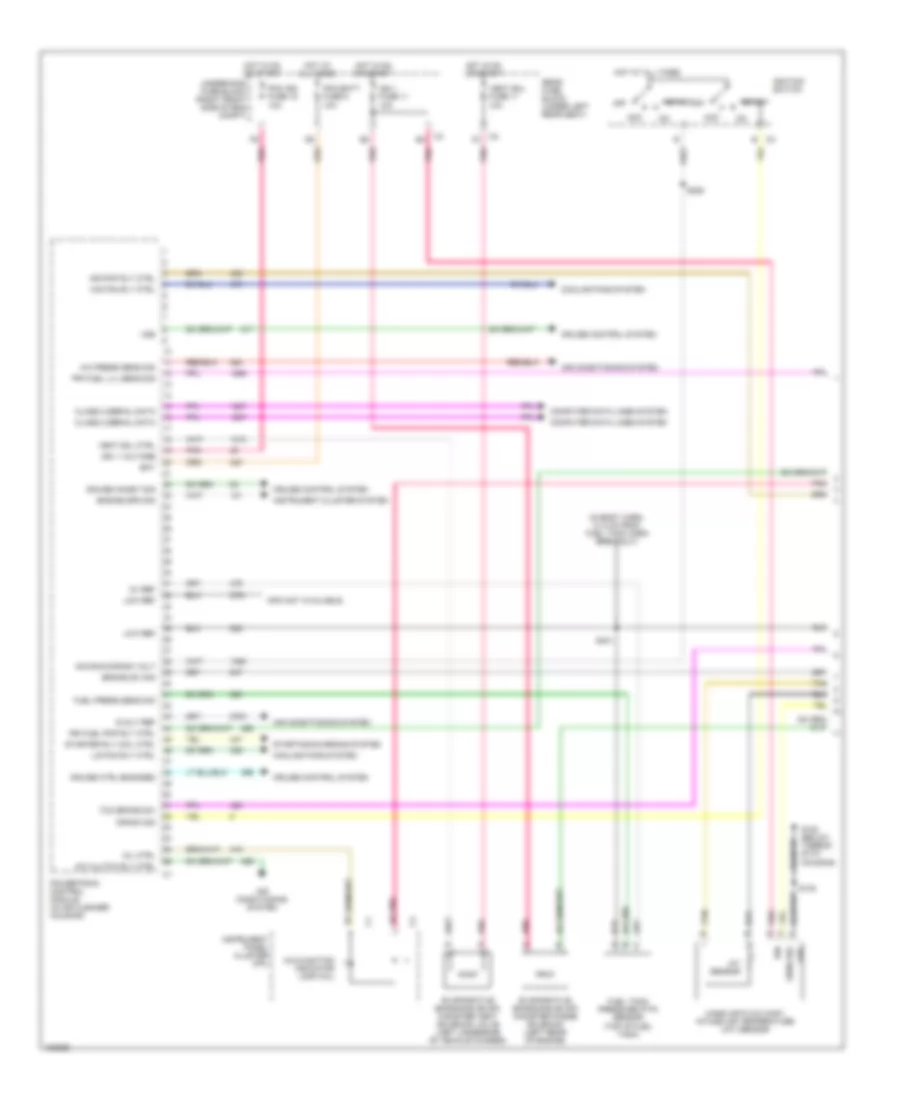
4.6L VIN A, Engine Performance Wiring Diagram (2 of 5) for Pontiac Bonneville SE 2004
List of elements for 4.6L VIN A, Engine Performance Wiring Diagram (2 of 5) for Pontiac Bonneville SE 2004:
- (below thermostat housing)
- (right front side of eng compt) underhood fuse block
- (top of fuel tank) fuel pump & sender assembly
- Air ctrl vlv relay
- Air pump fuse 45 50a
- Automatic transaxle
- Automatic transaxle internal mode switch (ims)
- Cruise control system
- Extended travel brake switch
- F/pmp fuse 1 20a
- F/pmp relay
- Fuel level sensor
- Fuel pump
- G108
- G111 (below thermostat housing)
- G302 (under rear seat)
- G401 (lower right corner of rear compt)
- Heated oxygen sensor (ho2s) bank 1 sensor 1 (in exhaust manifold)
- Heated oxygen sensor (ho2s) bank 1 sensor 2 (in exhaust manifold)
- Heated oxygen sensor (ho2s) bank 2 sensor 1 (in exhaust manifold)
- Hot at all times
- Hot in on or start
- Ign 1 fuse 11 10a
- Ign 1 fuse 12 10a
- Nca
- Pnk
- Rear fuse block (under left rear seat)
- Red
- S130
- S216
- Secondary air injection (air) check valve assembly
- Secondary air injection (air) pump (left front of eng compt)
- Secondary air injection (air) pump relay
- Splice pack sp302
- Splice pack sp401
- Stop lamp switch (lower left side of dash)
- Tan
- Tcc brake switch signal
- Trans fuse 10a
4.6L VIN A, Engine Performance Wiring Diagram (3 of 5) for Pontiac Bonneville SE 2004
List of elements for 4.6L VIN A, Engine Performance Wiring Diagram (3 of 5) for Pontiac Bonneville SE 2004:
- 1-2 shft sol ctrl
- 1-2 shift solenoid valve
- 2-3 shift sol
- 2-3 shift solenoid valve
- Anti-lock brakes system
- At iss high sig
- At iss low sig
- Automatic trans- axle fluid pressure manual valve position switch
- Automatic trans- axle input shaft speed (iss) sensor
- Automatic transaxle
- Automatic transaxle fluid temper- ature (tft) sensor
- C3 powertrain control module (in air cleaner housing)
- Del torque sig
- E pnk
- Fluid press sw a sig
- Front/vss high sig
- Ho2s high sig (2/1)
- Ho2s htr low (2/1)
- Ho2s low sig (2/1)
- Iat sens sig
- Low ref (iat)
- Low ref (trans temp)
- Maf sens sig
- N pnk
- P red
- Pc sol high ctrl
- Pc sol vlv low ctrl
- Pnk
- Pressure control solenoid valve
- Red
- Req torque sig
- S113
- Switch a
- Switch b
- Tan
- Tcc sol ctrl
- Tft sens sig
- Torque converter clutch pulse width modulation (tcc pwm) solenoid valve
- Trans press sig c
- Trans range sw sig a
- Trans range sw sig b
- Trans range sw sig c
- U pnk
- Vehicle speed sensor (vss) (lower right side of engine)
- Vss/oss low sig
4.6L VIN A, Engine Performance Wiring Diagram (4 of 5) for Pontiac Bonneville SE 2004
List of elements for 4.6L VIN A, Engine Performance Wiring Diagram (4 of 5) for Pontiac Bonneville SE 2004:
- (left front of eng compt)
- A6 pnk
- A8 pnk
- B5 pnk
- B6 pnk
- B9 pnk
- C8 pnk
- C9 pnk
- Coil mdl fuse 20a
- D4 pnk
- D8 pnk
- D9 pnk
- E red
- E4 pnk
- Engine coolant temperature (ect) sensor (below throttle body)
- Exhaust gas recirculation (egr) valve
- F4 pnk
- Fuel injector
- G109
- Hot in on or start
- Idle air control (iac) valve (on throttle body)
- Ignition coil/ module
- Injr 1 fuse 21 10a
- Injr 2 fuse 16 10a
- Manifold absolute pressure (map) sensor (on throttle body)
- Oxy sen fuse 20 10a
- Pnk
- Red
- S142
- S144
- S146
- Stepper motor
- Throttle position (tp) sensor (right of throttle body)
- Underhood fuse block (right front side of eng compt)
4.6L VIN A, Engine Performance Wiring Diagram (5 of 5) for Pontiac Bonneville SE 2004
List of elements for 4.6L VIN A, Engine Performance Wiring Diagram (5 of 5) for Pontiac Bonneville SE 2004:
- (below thermostat housing)
- (left front of eng compt)
- (left side of eng) engine oil level switch
- (left side of engine) crankshaft position (ckp) sensor a
- (left side of engine) crankshaft position (ckp) sensor b
- (lower left side of eng) knock sensor (ks) bank 2
- (near starter motor) knock sensor (ks) bank 1
- (right front of engine) camshaft position (cmp) sensor
- 12v ref
- 5v ref
- 5v ref (map)
- Air sol rly ctrl
- Crank sens a sig
- Crank sens b sig
- Ect sens sig
- Egr sol ctrl
- Egr sol high ctrl
- Egr vlv position sig
- Engine oil pressure switch (left side of engine)
- Evap canister sol ctrl
- Fuel inj 1 ctrl
- Fuel inj 2 ctrl
- Fuel inj 3 ctrl
- Fuel inj 4 ctrl
- Fuel inj 5 ctrl
- Fuel inj 6 ctrl
- Fuel inj 7 ctrl
- Fuel inj 8 ctrl
- G108
- G109
- Gen field duty sig
- Gen turn on sig
- Grd
- His res sig
- Ho2s high sig (1/1)
- Ho2s high sig (1/2)
- Ho2s htr low (1/1)
- Ho2s htr low (1/2)
- Ho2s low sig (1/1)
- Ho2s low sig (1/2)
- Iac coil a high ctrl
- Iac coil a low ctrl
- Iac coil b high ctrl
- Iac coil b low ctrl
- Ic 1 ctrl
- Ic 2 ctrl
- Ic 3 ctrl
- Ic 4 ctrl
- Ic 5 ctrl
- Ic 6 ctrl
- Ic 7 ctrl
- Ic 8 ctrl
- Ignition coil/ module
- Ks 1 low ref
- Ks 1 sig
- Ks 2 sig
- Low ref
- Low ref (coolant sens)
- Low ref (crank ret)
- Low ref (egr)
- Low ref (est bank 1)
- Low ref (est bank 2)
- Low ref (map)
- Low ref (tps)
- Low ref ks 2
- Map sens sig
- Nca
- Oil lvl sw sig
- Oil press sw sig
- Pnk
- Pnk a
- Powertrain control module (in air cleaner housing)
- Red
- Red b
- S130
- S131
- S133
- S135
- Starting/ charging system
- Tp sens sig
EXTERIOR LIGHTS
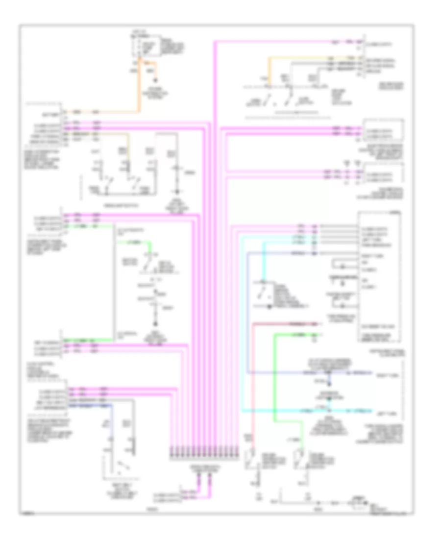
Exterior Lamps Wiring Diagram for Pontiac Bonneville SE 2004
List of elements for Exterior Lamps Wiring Diagram for Pontiac Bonneville SE 2004:
- (behind right side of dash, under sound insulator) dash integration module (dim)
- (in body harness, 12 cm from rear fuse block breakout) s309
- (in i/p wiring harness, 22 cm from instrument cluster breakout)
- (in i/p wiring harness, 9 cm from instrument cluster breakout) s250
- (in left taillamp harness, 16.5 cm from c400)
- (in rear compartment lid harness, 34.5 cm from p410 breakout) s411
- (in right taillamp harness, 16.5 cm from c402)
- (not used)
- 3.8l
- 4.6l
- Back light lamps control
- Batt
- Center high mounted stop lamp (chmsl)
- Dimr fuse 10a
- F12
- G103 (in front of underhood fuse block)
- G200 (on left front door pillar)
- G201 (on right front door pillar)
- G401 (on lower right corner of rear compt)
- G402 (on lower left corner of rear compt)
- Head-up display (hud)
- Headlamp dimmer switch
- Headlamp sw
- Headlamp sw sign
- Headlights system
- Hot at all times
- Hot in run or start
- Ign-1 fuse 10a
- Instrument panel cluster (ipc)
- Interior lights system
- L turn input
- L turn/hazard
- Left front park/ turn signal lamp
- Left license lamp
- Left rear marker lamp
- Left rear turn signal lamp
- Left tail/ stop lamp
- Left turn
- Left turn ind
- Left turn signal
- Logic
- Lp pk l fuse 10a
- Lp pk r fuse 10a
- Nca
- Of engine c1 compt)
- Park lamp sw sign
- Park lp relay
- Pk lp on input
- Pk lp sw
- Pnk
- Prk lp rly ctrl
- R turn input
- R turn/hazard
- Rear fuse block (under left rear seat)
- Right front park/ turn signal lamp
- Right license lamp
- Right rear marker lamp
- Right rear turn signal lamp
- Right tail/ stop lamp
- Right turn
- Right turn ind
- Right turn signal
- S203
- S216 pnk
- S251
- S406
- S407
- S408
- S409
- S410
- Sp103
- Sp200
- Sp201
- Sp304 (in body harness, 8.5 cm from g300 breakout)
- Sp401
- Sp402
- Stop lamp/ at shift lock control switch (lower left side of dash) c1
- Stop lp fuse 15a
- Tsig/ haz fuse 15a
- Turn signal/ multifunction switch
- Turn signal/hazard flasher module (behind center of dash, integral to hazard flasher switch)
- Underhood fuse block (right front side c1
3.8L VIN K
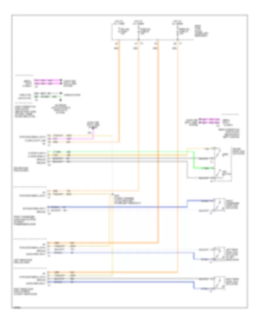
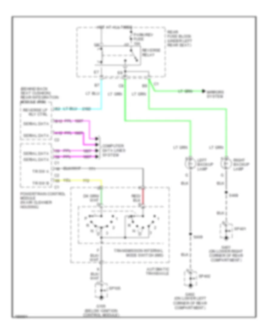
3.8L VIN K, Backup Lamps Wiring Diagram for Pontiac Bonneville SE 2004
List of elements for 3.8L VIN K, Backup Lamps Wiring Diagram for Pontiac Bonneville SE 2004:
- (behind back seat cushion) rear integration module (rim)
- A12
- Automatic transaxle
- B12
- Computer data lines system
- Corner of rear compartment)
- G105 (below ignition control module)
- G401 (on lower right corner of rear compartment)
- G402 (on lower left
- Hot at all times
- Left backup lamp
- Mirrors system
- Park/rev fuse 10a
- Powertrain control module (in air cleaner housing)
- Rear fuse block (under left rear seat)
- Reverse lp rly ctrl
- Reverse relay
- Right backup lamp
- S408
- S409
- Serial data
- Sp105
- Sp401
- Sp402
- Tr sw a
- Tr sw b
- Transmission internal mode switch (ims)
4.6L VIN A
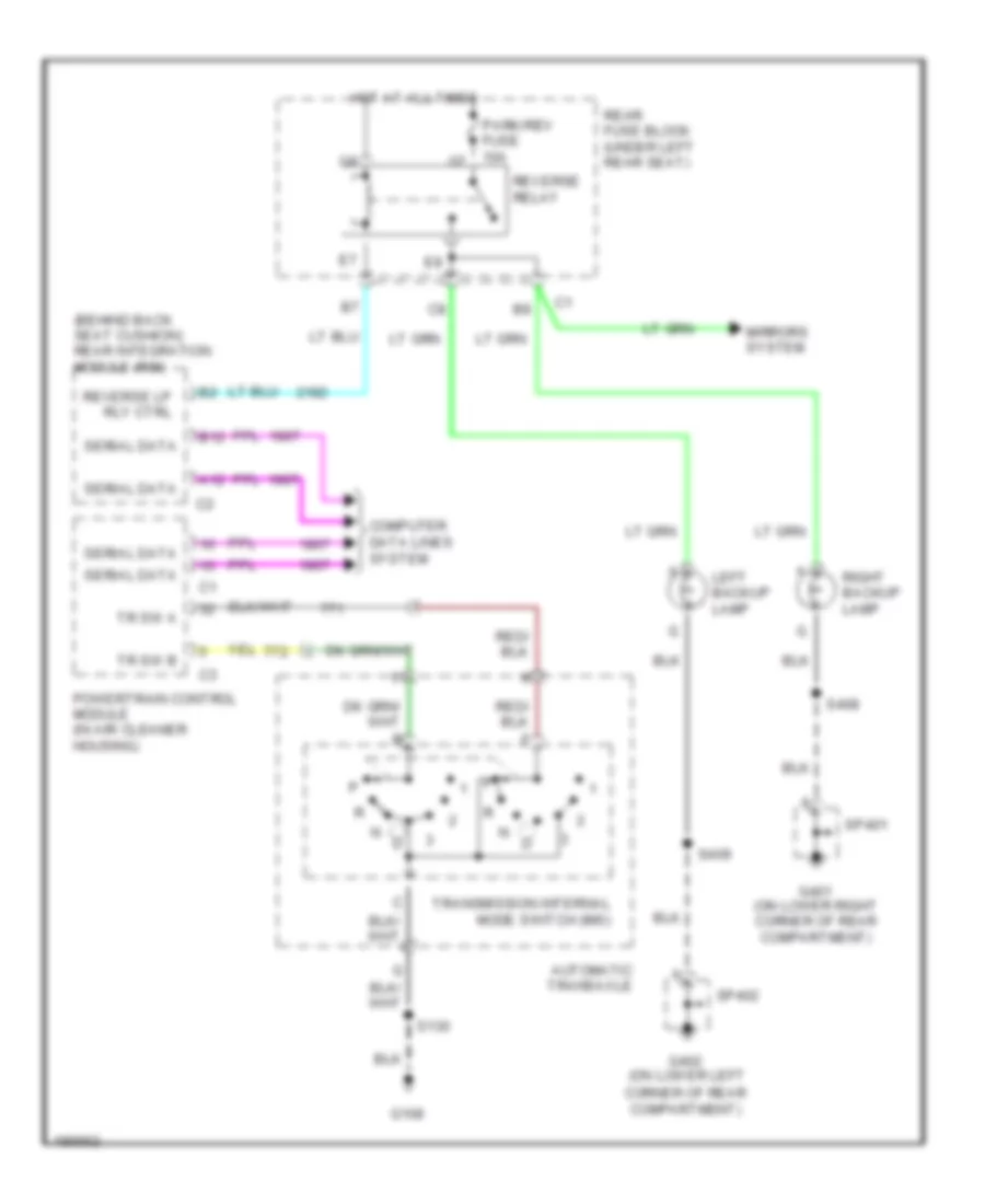
4.6L VIN A, Backup Lamps Wiring Diagram for Pontiac Bonneville SE 2004
List of elements for 4.6L VIN A, Backup Lamps Wiring Diagram for Pontiac Bonneville SE 2004:
- (behind back seat cushion) rear integration module (rim)
- A12
- Automatic transaxle
- B12
- Computer data lines system
- Corner of rear compartment)
- G108
- G401 (on lower right corner of rear compartment)
- G402 (on lower left
- Hot at all times
- Left backup lamp
- Mirrors system
- Park/rev fuse 10a
- Powertrain control module (in air cleaner housing)
- Rear fuse block (under left rear seat)
- Reverse lp rly ctrl
- Reverse relay
- Right backup lamp
- S130
- S408
- S409
- Serial data
- Sp401
- Sp402
- Tr sw a
- Tr sw b
- Transmission internal mode switch (ims)
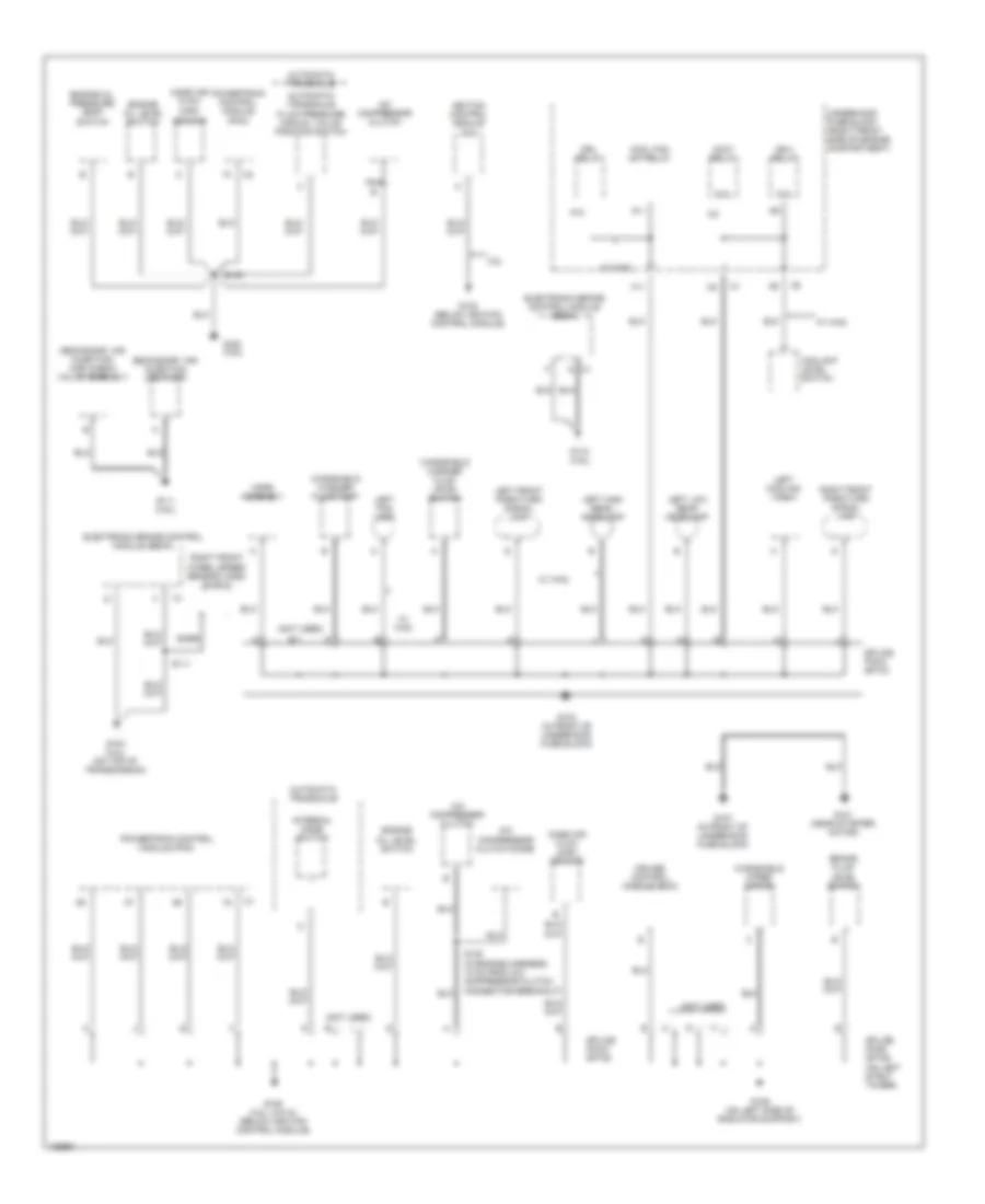
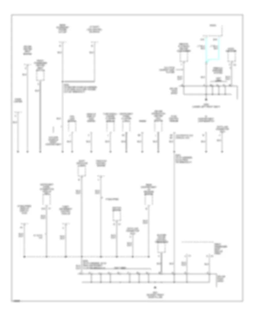
GROUND DISTRIBUTION
Ground Distribution Wiring Diagram (1 of 5) for Pontiac Bonneville SE 2004
List of elements for Ground Distribution Wiring Diagram (1 of 5) for Pontiac Bonneville SE 2004:
- (maf) sensor
- (not used)
- 3.8l
- A/c compressor clutch
- A/c compressor clutch diode
- A11
- Accy relay
- Automatic transaxle
- Automatic transaxle fluid pressure manual valve position switch
- Bare
- Brake fluid level switch
- Coil
- Cool fan s/p relay
- Coolant level switch
- Cruise control module (ccm)
- Drl relay
- Electronic brake control module (ebcm)
- Engine oil level switch
- Engine oil pressure (eop) switch
- F11
- G101 (near starter motor)
- G102 (below ignition control module)
- G103 (in front of underhood fuse block)
- G104 (3.8l) (on top of transmission)
- G105 (3.8l (vin k)) (below ignition control module)
- G106 (on left side of radiator support)
- G107 (in front of underhood fuse block)
- G108 (4.6l)
- G110 (4.6l)
- G111 (4.6l)
- Horn assembly
- Ign-1 relay
- Ignition control module (icm)
- Internal mode switch
- Left cooling fan
- Left fog lamp
- Left front park/turn signal lamp
- Left high beam headlamp
- Left low beam headlamp
- Mass air flow
- Mass air flow (maf) sensor
- Nca
- P10
- Powertrain control module (pcm)
- Right front park/turn signal lamp
- Right front wheel speed sensor (wss) shield
- S108 (in engine harness, 18 cm from a/c compressor clutch connector breakout)
- S111
- S130
- Secondary air injection (air) check valve assembly
- Secondary air injection (air) pump
- Splice pack sp103
- Splice pack sp105
- Splice pack sp106 (on left strut tower)
- Underhood fuse block (right front side of engine compartment)
- W/ wa2
- Windshield washer fluid level switch
- Windshield washer fluid pump
- Windshield wiper motor
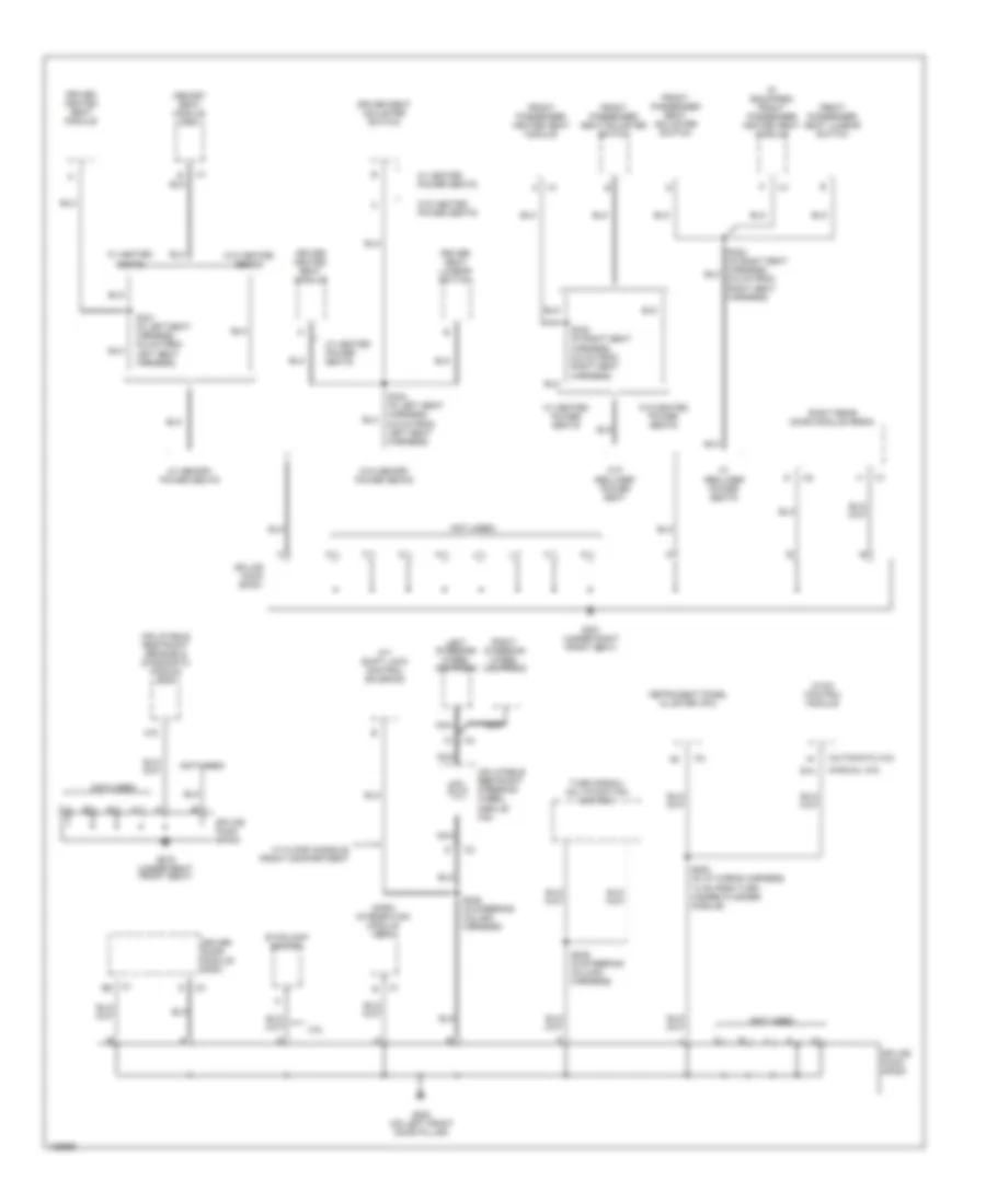
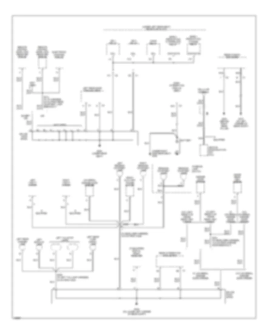
Ground Distribution Wiring Diagram (2 of 5) for Pontiac Bonneville SE 2004
List of elements for Ground Distribution Wiring Diagram (2 of 5) for Pontiac Bonneville SE 2004:
- (automatic a/c)
- (if equipped) front passenger heated seat module
- (manual a/c)
- (not used)
- 3.8l
- A/t shift lock control solenoid
- A18
- B14
- Dash integration module (dim)
- Driver door module (ddm)
- Driver heated seat module
- Driver seat adjuster switch
- Driver seat lumbar switch
- Front passenger heated seat module
- Front passenger seat adjuster switch
- Front passenger seat lumbar switch
- G200 (on left front door pillar)
- G301 (under right front seat)
- G303 (under right front seat)
- Hvac control module
- Inflatable restraint sensing & diagnostic module (sdm)
- Inflatable restraint steering wheel module coil
- Instrument panel cluster (ipc)
- Left steering wheel controls
- Memory seat module (msm)
- Nca
- Right rear door module (rrdm)
- Right steering wheel controls
- S225 (in steering column harness)
- S226 (in steering column harness)
- S253 (in i/p wiring harness, 13 cm from turn hazard flasher module)
- S321 (in left seat harness, 9.5 cm from left seat harness)
- S322 (in right seat harness, 9.5 cm from right seat harness)
- S324 (in left seat harness, 9.5 cm from left seat harness)
- Splice pack sp200
- Splice pack sp301
- Splice pack sp303
- Stoplamp switch
- Turn signal/ multifunction switch
- W/ floor console front compartment
- W/ heated power seats
- W/ heated seats
- W/ memory power seats
- W/ recliner power seats
- W/o heated power seats
- W/o heated seats
- W/o memory power seats
- W/o recliner power seat
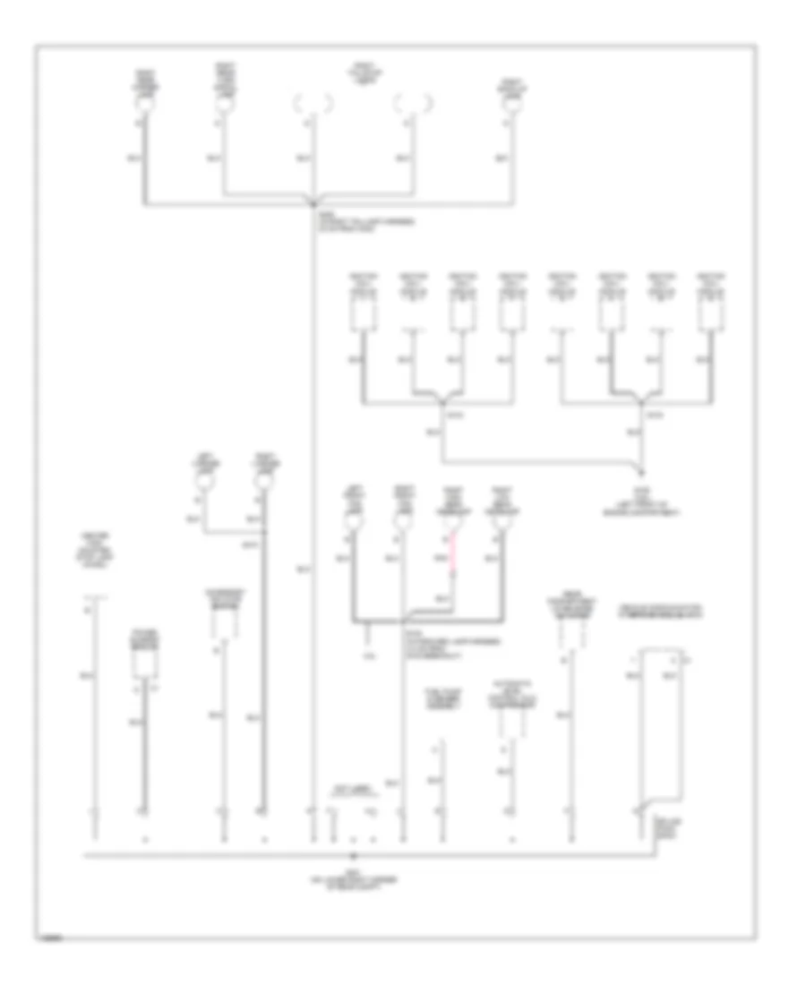
Ground Distribution Wiring Diagram (3 of 5) for Pontiac Bonneville SE 2004
List of elements for Ground Distribution Wiring Diagram (3 of 5) for Pontiac Bonneville SE 2004:
- (automatic a/c) (manual a/c)
- (if equipped) head up display (hud)
- (not used)
- A/t shift lock control solenoid
- A16
- A5 b3
- Audio amplifier
- B16
- Blower motor control processor
- Cigar lighter
- Cluster breakout)
- D16
- Data link connector (dlc)
- Driver heated seat switch
- Driver information center (dic) switch
- Fog lamp switch
- Front passenger door module (fpdm)
- Front passenger heated seat switch
- G201 (on right front door pillar)
- G300 (under left front seat)
- Head-up display (hud) switch
- Hvac control module
- If equipped
- Ignition switch
- Instrument panel cluster (ipc)
- Instrument panel integration module (ipm)
- Ip compartment lamp & switch
- Multiple compact disc player
- Premium speaker system
- Radio
- Rear accessory power outlet
- Rear compartment lid release switch
- Remote playback device/ cd changer
- S203 (in i/p harness, 6.5 cm from ipm breakout)
- S228 (in center console harness, 10 cm from auxiliary power outlet breakout)
- Shift indicator lamp
- Splice pack sp201
- Splice pack sp300
- Theft deterrent control module
- Traction control switch
- Turn signal/ hazard flasher module
- W/ auto a/c
- W/floor console front compartment
Ground Distribution Wiring Diagram (4 of 5) for Pontiac Bonneville SE 2004
List of elements for Ground Distribution Wiring Diagram (4 of 5) for Pontiac Bonneville SE 2004:
- (early production) f/tnkdr relay
- (early production) f/tnkdrlock relay
- (if equipped) digital radio receiver
- (in headliner harness, 15.6 cm from c329)
- (not used)
- (under left rear seat) rear fuse block
- (under right side rear seat) g305
- 13.5 cm from garage door breakout)
- A11
- B12
- Battery
- Cellular antenna
- Coil
- Contacts
- Dash integration module (dim)
- Electronic compass module
- Except u50
- F/pmp relay
- Front auxiliary power outlet
- G302 (under rear seat)
- G310 (on left corner of rear compt)
- G402 (on lower left corner of rear compt)
- G404 (behind right rear pillar)
- Garage door opener
- H12
- If equipped
- Ign 1 relay
- Ign 3 relay
- Inside rear view mirror
- Interior lamp switch
- J10
- Left back-up lamp
- Left reading/ courtesy lamp
- Left rear door module (lrdm)
- Left rear marker lamp
- Left rear turn signal lamp
- Left tail/stop lamps
- Left vanity mirror
- Nca
- Reading/ courtesy lamps
- Rear integration module (rim)
- Rear window defogger
- Remote control door lock receiver (rcdlr)
- Right reading/ courtesy lamp
- Right vanity mirror
- S329
- S409 (in left taillamp harness, 23 cm from c400)
- Splice pack sp302
- Splice pack sp402
- U50
- Universal garage door opener
- Vehicle communication unit (vcu)
- W/ universal garage door opener
- W/light sensitive inside rear view mirror
- W/o light sensitive inside rear view mirror
- W/o universal garage door opener
Ground Distribution Wiring Diagram (5 of 5) for Pontiac Bonneville SE 2004
List of elements for Ground Distribution Wiring Diagram (5 of 5) for Pontiac Bonneville SE 2004:
- (not used)
- 3.8l
- Accessory inflator switch
- Automatic level control (alc) compressor
- Center high mounted stop lamp (chmsl)
- Fuel pump & sender assembly
- G109 (4.6l) (left front of engine compartment)
- G401 (on lower right corner of rear compt)
- Ignition coil/ module
- Left front fog lamp
- Left license lamp
- Pnk
- Power sunroof module
- Rear compartment lid release actuator
- Right back-up lamp
- Right front fog lamp
- Right high beam headlamp
- Right license lamp
- Right low beam headlamp
- Right rear marker lamp
- Right rear turn signal lamp
- Right tail/stop lamps
- S100 (in forward lamp harness, 4.0 cm from g103 breakout)
- S133
- S144
- S408 (in right taillamp harness, 23 cm from c402)
- S410
- Splice pack sp401
- Vehicle communication interface module (vcim)
HEADLIGHTS
3.8L VIN K
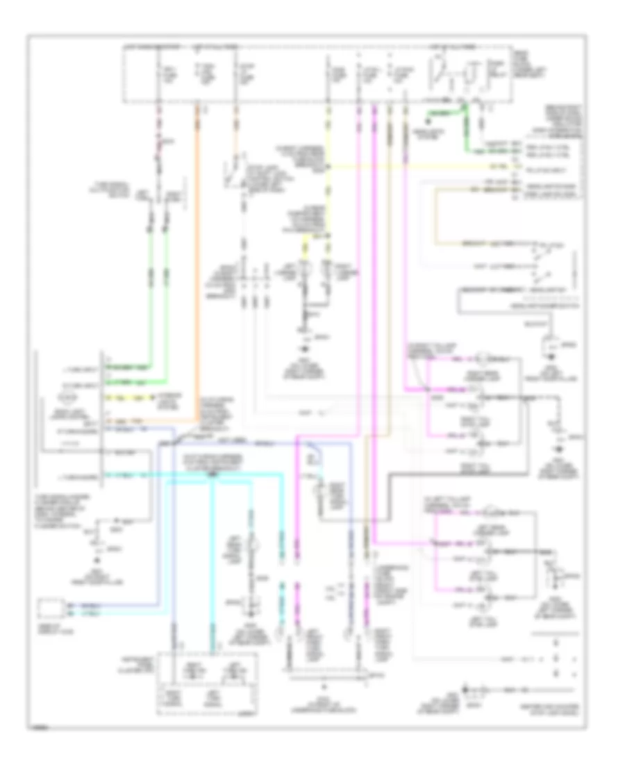
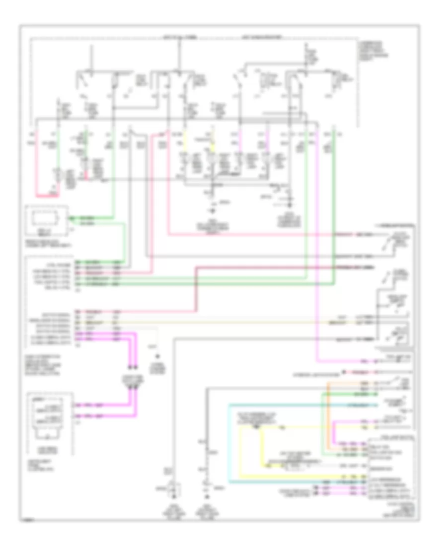
3.8L VIN K, Headlights Wiring Diagram, with Auto A/C for Pontiac Bonneville SE 2004
List of elements for 3.8L VIN K, Headlights Wiring Diagram, with Auto A/C for Pontiac Bonneville SE 2004:
- (in i/p harness, 2 cm from instrument cluster breakout)
- (on top center of dash) sunload sensor assembly
- 5 volt reference
- A11
- A12
- Air conditioning system
- B10
- B11
- B12
- C1 f11
- C10
- C11
- Class 2 serial data
- Computer data lines system
- Ctrl power
- Dash integration module (dim) (behind right side of dash, under sound insulator)
- Delay sig
- Drl relay
- Drl rly ctrl
- E11
- Flash- to-pass switch
- Fog lamp ind
- Fog lamp rly ctrl
- Fog lamp sw
- Fog lamp sw sig
- Fog lamp switch
- Fog lp relay
- Fog/ drl fuse 15a
- G103 (in front of underhood fuse block)
- G200 (on left front door pillar)
- G201 (on right front door pillar)
- G401 (on lower right corner of rear compt)
- Hdhi- bml fuse 10a
- Hdhi- bmr fuse 10a
- Hdlo- bml fuse 10a
- Hdlo- bmr fuse 10a
- Hdlp hi bm relay
- Hdlp lo bm relay
- Headlamp switch
- Headlamp switch off
- Headlamps on signal
- Hi/low headlamp beam switch
- High beam indicator
- High beam rly ctrl
- Hot at all times
- Hot in run or start
- I/p dimmer switch
- Instrument panel cluster (ipc)
- Instrument panel integration module (behind left side of dash)
- Interior lights system
- J10
- J11
- L10
- L11
- Left front fog lamp
- Left high beam head- lamp
- Left low beam head- lamp
- Logic
- Low beam rly ctrl
- Low reference
- M10
- M11
- N11
- Nca
- Off
- P10
- P11
- Pk lp switch
- Pnk
- Prk lp relay
- Rear fuse block (under left rear seat)
- Right front fog lamp
- Right high beam head- lamp
- Right low beam head- lamp
- S100
- S203
- S204
- Sensor sig
- Sp103
- Sp200
- Sp201
- Sp401
- Switch on signal
- Switch sig
- Switch signal
- Twilight delay sw
- Underhood fuse block (right front side of engine compt)
- Wiper/ washer system
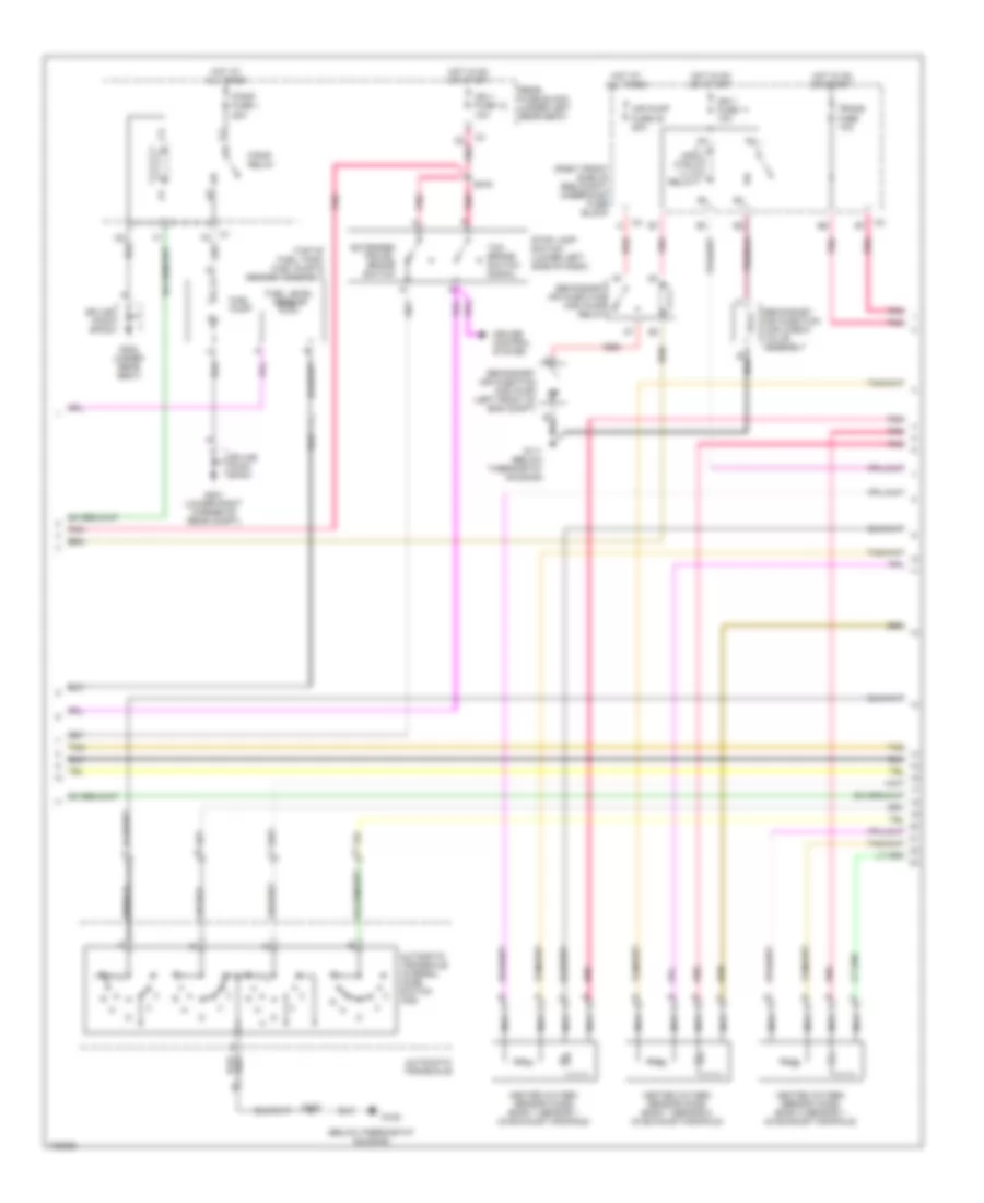
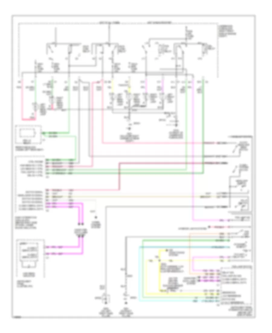
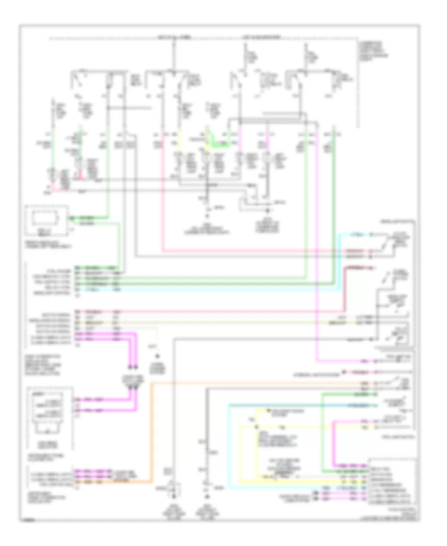
3.8L VIN K, Headlights Wiring Diagram, with Manual A/C for Pontiac Bonneville SE 2004
List of elements for 3.8L VIN K, Headlights Wiring Diagram, with Manual A/C for Pontiac Bonneville SE 2004:
- (in i/p harness, 2 cm from instrument cluster breakout) s204
- (on top center of dash) sunload sensor assembly
- 5 volt reference
- A11
- A12
- B10
- B11
- C1 f11
- C10
- C11
- Class 2 serial data
- Computer data lines system
- Ctrl power
- Dash integration module (dim) (behind right side of dash, under sound insulator)
- Delay sig
- Drl relay
- Drl rly ctrl
- E11
- Flash- to-pass switch
- Fog lamp ind
- Fog lamp rly ctrl
- Fog lamp sw
- Fog lamp sw sig
- Fog lamp switch
- Fog lp relay
- Fog/ drl fuse 15a
- G103 (in front of underhood fuse block)
- G200 (on left front door pillar)
- G201 (on right front door pillar)
- G401 (on lower right corner of rear compt)
- Hdhi- bml fuse 10a
- Hdhi- bmr fuse 10a
- Hdlo- bml fuse 10a
- Hdlo- bmr fuse 10a
- Hdlp hi bm relay
- Hdlp lo bm relay
- Headlamp switch
- Headlamp switch off
- Headlamps on signal
- Hi/low headlamp beam switch
- High beam indicator
- High beam rly ctrl
- Hot at all times
- Hot in run or start
- Hvac control module (located in center of dash)
- I/p dimmer switch
- Instrument panel cluster (ipc)
- Interior lights system
- J10
- J11
- L10
- L11
- Left front fog lamp
- Left high beam head- lamp
- Left low beam head- lamp
- Logic
- Low beam rly ctrl
- Low reference
- M10
- M11
- N11
- Nca
- Off
- P10
- P11
- Pk lp switch
- Pnk
- Prk lp relay
- Rear fuse block (under left rear seat)
- Right front fog lamp
- Right high beam head- lamp
- Right low beam head- lamp
- S100
- S203
- Sensor sig
- Sp103
- Sp200
- Sp201
- Sp401
- Switch on signal
- Switch sig
- Switch signal
- Twilight delay sw
- Underhood fuse block (right front side of engine compt)
- Wiper/ washer system
4.6L VIN A
4.6L VIN A, Headlights Wiring Diagram for Pontiac Bonneville SE 2004
List of elements for 4.6L VIN A, Headlights Wiring Diagram for Pontiac Bonneville SE 2004:
- (in i/p harness, 2 cm from instrument cluster breakout)
- (on top center of dash) sunload sensor assembly
- 5 volt reference
- A11
- A12
- Air conditioning system
- B10
- B11
- C10
- C11
- Class 2 serial data
- Computer
- Computer data lines system
- Ctrl power
- Dash integration module (dim) (behind right side of dash, under sound insulator)
- Data lines
- Delay sig
- Drl fuse 15a
- Drl relay
- Drl rly ctrl
- E11
- Flash- to-pass switch
- Fog fuse 15a
- Fog lamp ind
- Fog lamp rly ctrl
- Fog lamp sw
- Fog lamp sw sig
- Fog lamp switch
- Fog lp relay
- G103 (in front of underhood fuse block)
- G200 (on left front door pillar)
- G201 (on right front door pillar)
- G401 (on lower right corner of rear compt)
- Hdhi- bml fuse 10a
- Hdhi- bmr fuse 10a
- Hdlo- bml fuse 10a
- Hdlo- bmr fuse 10a
- Hdlp hi bm relay
- Hdlp lo bm relay
- Headlamp control
- Headlamp switch
- Headlamp switch off
- Headlamps on signal
- Hi/low headlamp beam switch
- High beam indicator
- High beam rly ctrl
- Hot at all times
- Hot in on or start
- Hvac control module (located in center of dash)
- I/p dimmer switch
- Instrument panel cluster (ipc)
- Instrument panel integration module (ipm)
- Interior lights system
- J10
- J11
- L10
- L11
- Left front fog lamp
- Left high beam head- lamp
- Left low beam head- lamp
- Logic
- Low reference
- M10
- M11
- Nca
- Off
- P10
- P11
- Pk lp switch
- Pnk
- Prk lp relay
- Rear fuse block (under left rear seat)
- Right front fog lamp
- Right high beam head- lamp
- Right low beam head- lamp
- S100
- S203
- S204
- Sensor sig
- Sp103
- Sp200
- Sp201
- Sp401
- Switch on signal
- Switch sig
- Switch signal
- System
- Twilight delay sw
- Underhood fuse block (right front side of engine compt)
- Wiper/ washer system
HORN
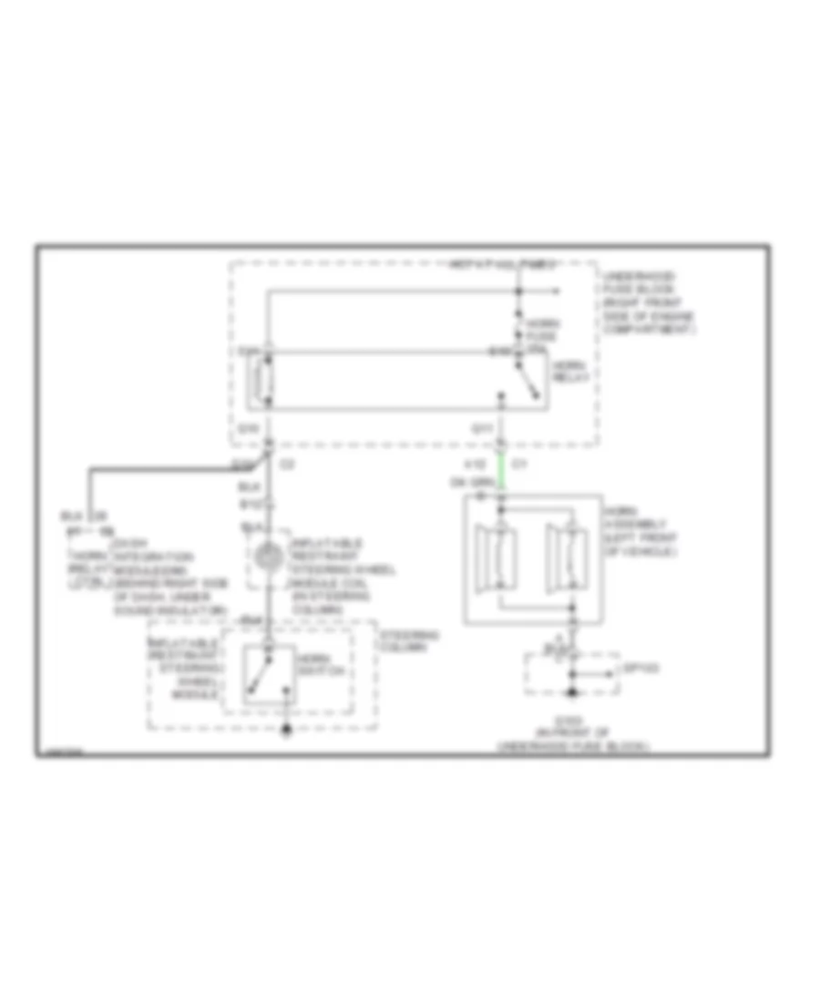
Horn Wiring Diagram for Pontiac Bonneville SE 2004
List of elements for Horn Wiring Diagram for Pontiac Bonneville SE 2004:
- (in front of underhood fuse block)
- A12
- B12
- D10
- Dash integration module(dim) (behind right side of dash, under sound insulator)
- G103
- Horn assembly (left front of vehicle)
- Horn fuse 15a
- Horn relay
- Horn relay ctrl
- Horn switch
- Hot at all times
- Inflatable restraint steering wheel module
- Inflatable restraint steering wheel module coil (in steering column)
- Q10
- Q11
- S10
- S11
- Sp103
- Steering column
- Underhood fuse block (right front side of engine compartment)
INSTRUMENT CLUSTER
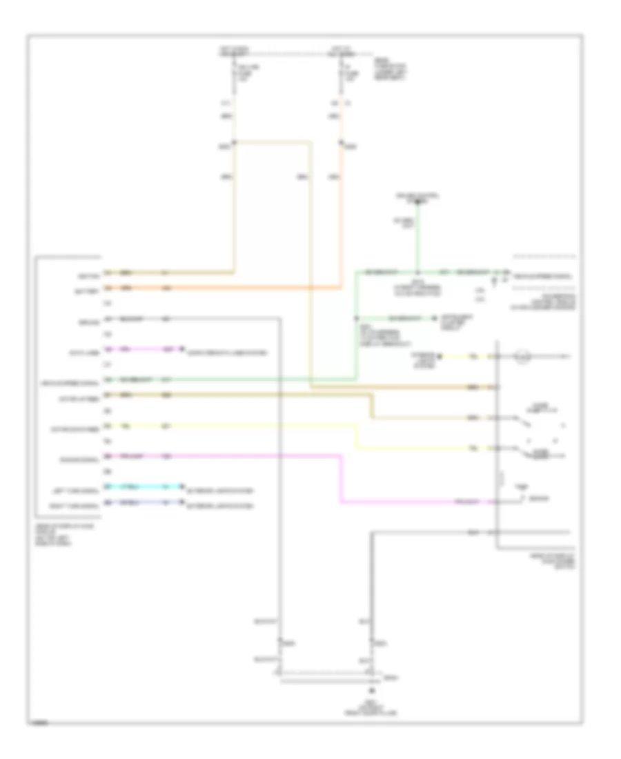
Head-Up Display Wiring Diagram for Pontiac Bonneville SE 2004
List of elements for Head-Up Display Wiring Diagram for Pontiac Bonneville SE 2004:
- 3.8l
- 4.6l
- Battery
- C11
- Computer data lines system
- Cruise control system
- Data lines
- Dimming
- Dimming signal
- Exterior lights system
- G201 (on right front door pillar)
- Ground
- Head-up display (hud) dimmer switch
- Head-up display (hud) module (on top left side of dash)
- Hot at all times
- Hot in run or start
- Ign 3 rr fuse 10a
- Ignition
- Image down
- Image up
- Instrument cluster circuit
- Interior lights system
- Ip fuse 10a
- Left turn signal
- Motor down feed
- Motor up feed
- Powertrain control module (in air cleaner housing)
- Rear fuse block (under left rear seat)
- Right turn signal
- S200
- S201 (in i/p harness, 10 cm from hud display breakout)
- S203
- S205
- S206
- S215 (in body harness, 19.5 cm from p100)
- Sp201
- Vehicle speed signal
- Vehicle speed signal c1
Instrument Cluster Wiring Diagram (1 of 2) for Pontiac Bonneville SE 2004
List of elements for Instrument Cluster Wiring Diagram (1 of 2) for Pontiac Bonneville SE 2004:
- (or 1055)
- (w/ u2f)
- (w/ u50)
- Abs ind
- Anti-lock ind control
- Battery
- Brake ind
- Brk fluid in
- C11
- Check oil level ind
- Clock sig
- Compass clk
- Compass data
- Computer data lines system
- Coolant level sw sig
- Cooling fans system
- Data lines
- Data sig
- Driver information center (dic)
- Electronic compass module (under left side of rear shelf)
- Eng/met sig
- Engine coolant temperature gauge
- Engine oil pressure gauge
- Engine speed signal
- Exterior lights system
- Fuel gauge
- G200 (on left front door pillar)
- G302 (under rear seat)
- Ground
- High beam ind
- Hot at all times
- Hot in acc or run
- Hot in on
- Ign 1 fuse 10a
- Ign 3 rr fuse 10a
- Ign 3 voltage
- Ignition
- Instrument panel cluster (ipc)
- Ip fuse 10a
- Left turn ind
- Logic
- Low trac ind
- Lt turn sig
- Malfunction ind lamp
- Mode sig
- Odometer
- P r
- Pnk
- Prk brk in
- R defog
- Rear fuse block (under left rear seat)
- Rear integration module (behind upper left rear seat cushion)
- Reset sig
- Right turn ind
- Rt turn sig
- S206
- S216
- S253
- S307
- S414
- Security ind
- Select sig
- Sp200
- Sp302
- Speedometer
- Tachometer
- Tire inflate
- Trac off ind
- Trac ready ind control
- Trip a/b
- Trip reset sig
- Vehicle speed signal
- Vf display
- Volt gauge (w/ u50)
- Washer fluid ind
- Washer level sw signal
- Wiper/washer system
Instrument Cluster Wiring Diagram (2 of 2) for Pontiac Bonneville SE 2004
List of elements for Instrument Cluster Wiring Diagram (2 of 2) for Pontiac Bonneville SE 2004:
- (3.8l: in oil pan) (4.6l: left side of engine) engine oil level switch
- (31.5 cm from fuel tank harness breakout) s401
- (left side of engine) (4.6l) engine oil pressure (eop) switch
- (on front of engine, below power steering pump) (3.8l) engine oil pressure (eop) sensor
- (on left side of radiator support) g106
- (on top of fuel tank) fuel pump & sender assembly
- 3.8l
- 4.6l
- Air bag ind
- Anti-lock brakes system
- Battery charge ind
- Brake fluid level switch (in master cylinder reservoir)
- Check gauges ind
- Cruise control system
- Ctrl abs ind
- Door ajar ind
- Driver information center (dic) switch (w/ u2f)
- Driver information center (dic) switch (w/ u50)
- Electronic brake control module (ebcm) (on left front of engine compt)
- Eng/ met
- Fasten safety belt ind
- Fuel level sens
- G105 (below ignition control module)
- G108
- G201 (on right front door pillar)
- Head-up display (hud) module (on top left side of dash)
- Instrument panel cluster (ipc)
- Interior lights system
- Logic
- Low ref
- Mil control
- Mode
- Oil level sw sig
- Oil pressure sw
- Park brake switch (on top of park brake pedal assembly)
- Pnk
- Powertrain control module (in air cleaner housing)
- Ready ind
- Reset
- S130
- S201 (w/ head-up display) (in i/p harness, 10 cm from hud display breakout)
- S203
- S205
- S215 (in body harness, 19.5 cm from p100)
- Select
- Sens sig
- Service vehicle soon ind
- Sp105
- Sp106 (on left strut tower)
- Sp201
- Tach signal
- Tire press ind
- Tire reset
- Traction control switch
- Trip reset
- Trunk ajar ind
- Vss sig
- Vss signal
- W/ u2f
- W/ u50
INTERIOR LIGHTS
Courtesy Lamps Wiring Diagram (1 of 2) for Pontiac Bonneville SE 2004
List of elements for Courtesy Lamps Wiring Diagram (1 of 2) for Pontiac Bonneville SE 2004:
- (in body harness, 14.5 cm from left power seat breakout) s302
- (manual a/c) (automatic a/c)
- A1 c7
- A12
- A16 d13
- A2 c8
- B12
- Class 2 serial data line
- Computer data lines system
- D12
- Driver door lock actuator
- Driver door module (ddm)
- Driver door switch assembly (ddsa)
- E11
- E12
- Front passenger door lock actuator c1 a
- Front passenger door module (fpdm) (in front passenger's door)
- G401 (on lower right corner of rear compt)
- Ground
- Hot at all times
- Hvac control module (manual a/c) (located in center of dash)
- I/p fuse 10a
- Ignition key cylinder lamp
- Ignition key cylinder lamp control
- Inadvertent power relay control
- Instrument panel integration module (automatic a/c) (behind left side of dash)
- Int lp fuse 10a
- Int lp relay
- J11
- J12
- L11
- L12
- Left front door open input
- Left i/p courtesy lamp
- Left rear door lock actuator (in left rear door) c1 d
- Left rear door module (lrdm)
- Left rear door open input
- Rear compartment courtesy lamp
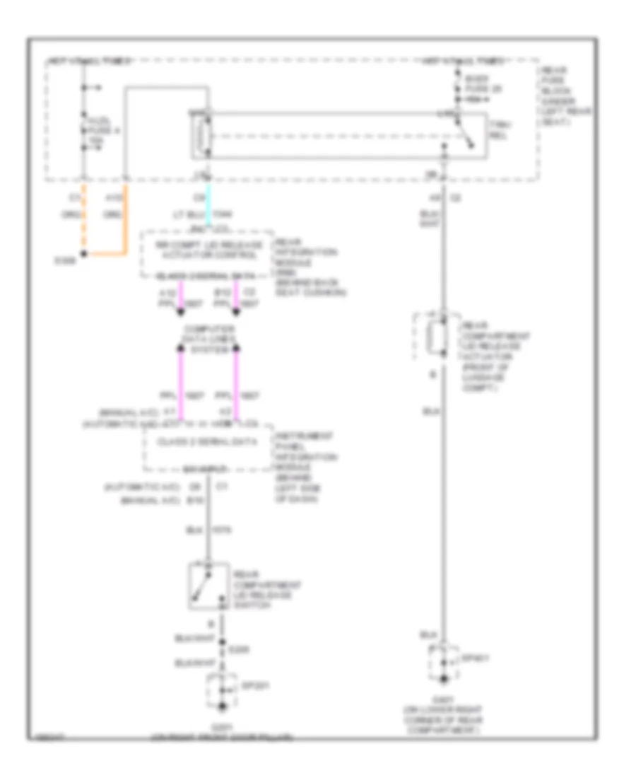
- Rear compartment lid release actuator (front of luggage compt)
- Rear compt lid ajar switch
- Rear fuse block (under left rear seat)
- Rear integration module (rim) (behind back seat cushion)
- Red/
- Right front door open input
- Right rear door lock actuator c1
- Right rear door module (rrdm) (in right rear door)
- Right rear door open input
- S206
- Simple bus interface (sbi)
- Sp306 (in body harness, 8 cm from rear fuse block breakout)
- Sp401
- Tan
- Tan/
- To s209 (diagram 2 of 2)
- To s333 (diagram 2 of 2)
- To sp310 (diagram 2 of 2)
Courtesy Lamps Wiring Diagram (2 of 2) for Pontiac Bonneville SE 2004
List of elements for Courtesy Lamps Wiring Diagram (2 of 2) for Pontiac Bonneville SE 2004:
- A10
- B10
- Courtesy lamp ground
- Courtesy lamp power input
- From left i/p courtesy lamp (diagram 1 of 2)
- From rear fuse block (diagram 1 of 2)
- From sp306 (diagram 1 of 2)
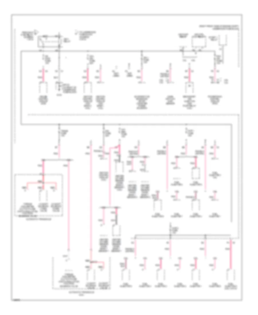
- G201 (on right front door pillar)
- G402 (on lower left corner of rear compt)
- I/p compartment lamp and switch
- Interior lamp switch
- Left reading/ courtesy lamp
- Left vanity mirror
- Rear integration module (rim) (behind back seat cushion)
- Right i/p courtesy lamp
- Right reading/ courtesy lamp
- Right vanity mirror
- S203
- S209 (in i/p harness, 13 cm from c204 & c205 breakout)
- S329
- S332 (in headliner harness, 183 cm from overhead console harness breakout)
- S333
- Sp201
- Sp306 (in body harness, 8 cm from rear fuse block breakout)
- Sp310 (in body harness, 18 cm from rear fuse block breakout)
- Sp402
Instrument Illumination Wiring Diagram (1 of 2) for Pontiac Bonneville SE 2004
List of elements for Instrument Illumination Wiring Diagram (1 of 2) for Pontiac Bonneville SE 2004:
- (automatic a/c) b1
- (in i/p harness, 19.5 cm from c204 & c205 breakout) s207
- (in steering column harness) s227
- (manual a/c) b14
- (manual a/c) b2
- A1 (automatic a/c)
- Ashtray lamp
- C1 a4
- Control power
- Dash integration module (dim) (behind right side of dash, under sound insulator)
- Dimr fuse 10a
- Driver heated seat switch
- Driver information center (dic) switch
- Fog lamp switch
- G200 (on left front door pillar)
- G201 (on right front door pillar)
- Head up display (hud) switch
- Hot at all times
- Hvac control module (located in center of dash)
- Incandescent dimming output
- Inflatable restraint steering wheel module coil (left kick panel)
- Instrument panel cluster (ipc)
- Left steering wheel controls
- Nca
- Nca b
- Park lamp input
- Park lamp relay control
- Passenger heated seat switch
- Prk lp relay
- Radio
- Rear fuse block (under left rear seat)
- Right steering wheel controls
- S203
- S205
- S225
- S228 (in center console harness, 10 cm from auxiliary power outlet breakout)
- S253
- Shift indicator lamp
- Sp200
- Sp201
- Sp304 (in body harness, 8.5 cm from g300 breakout)
- Steering column fuse holder (near base of steering column)
- Switch fuse 2a
- Traction control switch
- Turn signal/ hazard flasher switch
Instrument Illumination Wiring Diagram (2 of 2) for Pontiac Bonneville SE 2004
List of elements for Instrument Illumination Wiring Diagram (2 of 2) for Pontiac Bonneville SE 2004:
- (automatic a/c) (manual a/c)
- (in body harness, 14.5 cm from left power seat breakout) s302
- (in left front door trim harness, 19 cm from c503) s501
- (in right front door trim harness, 9 cm from c603 breakout) s603
- (manual a/c) (automatic a/c)
- 5v ref
- A1 c7
- A11
- A12
- A2 c8
- Air conditioning system
- B11 a4
- B12 b5
- B8 b6
- Backlight lamps ctrl
- C1 a4
- C1 a5
- C1 a6
- C2 a12
- C2 b12
- C2 c2
- C6 a11
- Class 2 serial data line
- Computer data lines system
- Dash integration module (dim) (behind right side of dash, under sound insulator)
- Door locks system
- Driver door lock switch
- Driver door module (ddm)
- Driver seat adjuster switch
- Driver window switch
- Fog lamp switch
- Front passenger door module (fpdm) (in front passenger's door)
- Front passenger power door lock switch
- Front passenger power window switch
- G200 (on left front door pillar)
- G201 (on right front door pillar)
- Ground
- Head
- Headlamp switch
- Hvac control module (manual a/c) (located in center of dash)
- I/p dimmer switch
- I/p dimmer switch input
- Instrument panel cluster (ipc)
- Instrument panel integration module (automatic a/c) (behind left side of dash)
- Interior lamp switch
- Interior lamp switch input
- Memory personalization adjuster switch
- Off
- Park
- Radio
- Rear integration module (rim) (behind back seat cushion)
- S203
- S204 (in i/p harness, 2 cm from instrument cluster breakout)
- S500 (in left front door trim harness, 19 cm from c503)
- S604 (in right front door trim harness, 21 cm from c603 breakout)
- Sensor return
- Simple bus interface (sbi)
- Sp200
- Sp201
MEMORY SYSTEMS
Memory Mirrors Wiring Diagram for Pontiac Bonneville SE 2004
List of elements for Memory Mirrors Wiring Diagram for Pontiac Bonneville SE 2004:
- (in left front door trim harness, 19 cm from c503 breakout) s500
- (or tan)
- A vertical position input
- A vertical position sensor signal
- B horizontal position input
- B horizontal position sensor signal
- Batt(+)
- Battery
- Door locks system
- Driver
- Driver 1 input
- Driver 2 input
- Driver door module
- Driver door switch assembly (ddsa)
- Driver outside rearview mirror
- Drv mdl fuse 10a
- E position sensors return
- Exit
- Front passenger door module (in front passenger's door)
- G200 (on left front door pillar)
- G201 (on right front door pillar)
- Gnd
- Heating element feed
- Heating element return
- Horizontal motor
- Hot at all times
- Interior lights system
- J right motor control
- K down motor control
- Left motor control
- M position sensors feed
- Memory personalization function switch
- Mirror heating element
- Motor control
- Pass mdl fuse 10a
- Passenger outside rearview mirror
- Rear fuse block (under left rear seat)
- S302 (in body harness, 14.5 cm from left power seat breakout)
- S602 (lesabre)
- Serial data
- Sp200
- Sp201
- Up l
- Vertical motor
Memory Seat Wiring Diagram for Pontiac Bonneville SE 2004
List of elements for Memory Seat Wiring Diagram for Pontiac Bonneville SE 2004:
- (in left seat harn, 16 cm from left seat harn)
- (in left seat harn, 21 cm from left seat harn)
- Batt
- Battery
- C (bonneville)
- C10
- C11
- C12
- C13
- C14
- C15
- C16
- Class 2 data
- Computer data lines system
- D (lesabre)
- D10
- D11
- D12
- D13
- D14
- D15
- D16
- Driver
- Driver 1 input
- Driver 2 input
- Driver door module
- Driver door switch assembly (ddsa)
- Driver front vertical position sensor (under driver seat)
- Driver seat adjuster switch
- Driver seat front vertical motor (under driver seat)
- Driver seat horizontal motor (under driver seat)
- Driver seat horizontal position sensor (under driver seat)
- Driver seat lumbar horizontal motor (left front seat back)
- Driver seat lumbar horizontal position sensor (left front seat back)
- Driver seat lumbar switch
- Driver seat lumbar vertical motor (left front seat back)
- Driver seat lumbar vertical position sensor (left front seat back)
- Driver seat rear vertical motor (under driver seat)
- Driver seat rear vertical position sensor (under driver seat)
- Driver seat recline motor (left front seat back)
- Driver seat recliner position sensor
- E12
- Entire
- Exit
- Frnt hgt mtr sens in
- Front
- Front height sw input
- Frt vert dn ctrl
- Frt vert up ctrl
- Fwd
- Fwd-bk mtr sens in
- Fwd/bk sw input
- G301 (on forward crossmember)
- Ground
- Horiz backward ctrl
- Horiz forward ctrl
- Hot at all times
- Interior lights system
- Lesabre in left lumbar harn, 5 cm from c14 connector) (bonneville: in left lumbar harn, 5 cm from c314)
- Lumbar down ctrl
- Lumbar down in
- Lumbar forward ctrl
- Lumbar in input
- Lumbar in/out sens in
- Lumbar out in
- Lumbar rearward ctrl
- Lumbar up ctrl
- Lumbar up in
- Lumbar up/dn sens in
- Mem fuse 10a
- Memory personalization function switch
- Memory seat module (under driver's seat)
- Nca
- Out
- Pnk
- Pnk a
- Position sensors feed
- Pwr seat circuit breaker 30a
- Rear
- Rear fuse block (under left rear seat)
- Rear height sw input
- Rear hgt mtr sens in
- Rear vert up ctrl
- Recline
- Recline back ctrl
- Recline forward ctrl
- Recline mtr sens in
- Recliner sw input
- Red
- S317
- S317 (in left seat harn, 11.5 cm from left seat harn)
- S319
- S320
- S321 (w/ heated seats)
- S330
- S331
- Serial data
- Solid state
- Sp301 (in body harness, 8.5 cm from g300 breakout)
- Tan
POWER DISTRIBUTION
Power Distribution Wiring Diagram (1 of 5) for Pontiac Bonneville SE 2004
List of elements for Power Distribution Wiring Diagram (1 of 5) for Pontiac Bonneville SE 2004:
- (right front side of engine compt) underhood fuse block
- 3.8l 4.6l
- A/c clu fuse 15a
- A/c clutch relay
- A10
- Abs
- Accy fuse 15a
- Accy relay
- Air fuse (3.8l) 30a
- Air pump fuse (4.6l) 50a
- Aux pwr (3.8l) c/ltr 1 (4.6l) fuse 20a
- B+ mode
- B12
- Battery
- Battery saver mode
- C/ltr (3.8l) c/ltr 2 (4.6l) fuse 20a
- Cigar lighter
- Cool fan 1 fuse 30a
- Cool fan 1 relay (low speed)
- Cool fan 2 fuse 30a
- Cool fan 2 relay (high) speed)
- Cool fan s/p relay
- D12
- Drl fuse 15a (4.6l)
- Drl relay (3.8l)
- Drl relay (4.6l)
- E12
- Electronic brake control module (ebcm)
- Floor console
- Fog fuse 10a (4.6l)
- Fog lp relay (3.8l)
- Fog lp relay (4.6l)
- Fog/ drl fuse 15a
- From fog/ b drl fuse (diagram 1 of 5)
- Front auxiliary power outlet
- Front compartment
- Fuse 50a
- G10
- G103
- G11
- G201
- G402
- Generator
- Hdlp lo bm relay
- Hdlp hi bm relay
- Horn fuse 15a
- Horn relay
- L10
- M11
- Nf7
- P11
- Pcm batt fuse 10a
- Pnk
- Powertrain control module (pcm)
- Rear auxiliary power outlet
- Red
- S10
- S11
- S228
- S329
- Secondary air injection (air) pump relay (4.6l)
- Sp103 (in front of underhood fuse block)
- Sp201 (on right front door pillar)
- Sp402 (on lower left corner of rear compt)
- Start 1 relay
- Start circuit breaker 30a
- Starter solenoid
- Theft deterrent control module
- To cigar relay (diagram 2 of 5)
- To hdlp lo bm relay (diagram 1 of 5)
- To ign-1 relay (diagram 5 of 5)
- To rear fuse block (diagram 2 of 5)
- To underhood fuse block (diagram 4 of 5)
- Underhood fuse block (right front side of engine compt)
- V10
- Wind- shield wiper motor
- Wind- shield wiper switch
- Wsw fuse 30a
Power Distribution Wiring Diagram (2 of 5) for Pontiac Bonneville SE 2004
List of elements for Power Distribution Wiring Diagram (2 of 5) for Pontiac Bonneville SE 2004:
- (in body harness, 5.5 cm from rear fuse block breakout) s308
- (in body harness, pnk 17 cm from p100) s216
- (under left rear seat) rear fuse block
- 4.6l
- A10
- A11
- A12
- A14
- Aldl fuse 10a
- Audio fuse 10a
- B12
- Body fuse 15a
- C10
- Cd changer remote playback device
- Cd fuse 10a
- Cigar fuse 40a
- Cigar relay
- D10
- D11
- D12
- Dash integration module (dim)
- Data link connector
- Dim fuse 10a
- Driver heated seat module
- Driver seat lumbar switch
- Driver seat switch (w/ memory)
- E11
- Evaporative emissions (evap) canister vent solenoid
- F/ pmp relay
- F/ tnkdr rel relay
- F/ trnkdr lock relay
- F/pmp fuse 20a
- F/tnkdr rel relay
- F/trnkdr lock relay
- From aux/pwr fuse (diagram 1 of 5)
- From battery a (diagram 1 of 5)
- From e cigar fuse (diagram 2 of 5)
- From f aldl fuse (diagram 2 of 5)
- Front passenger's heated seat module
- G302
- Garage door opener
- Generator
- H10
- Htdst lf fuse 10a
- Htdst rf fuse 10a
- Hvac batt fuse 10a
- Hvac control module
- Ign-1 fuse 10a
- Ign-1 relay
- Inflatable restraint sensing & diagnostic module (sdm)
- Inside rearview mirror
- Instrument panel cluster (ipc)
- Instrument panel integration module (ipm)
- Int lamp relay
- Int lp fuse 10a
- L10
- L11
- L12
- Mem fuse 10a
- Memory seat module (msm)
- N10
- Nca
- Park lp relay
- Park relay
- Pnk
- Power sun roof module
- Prk/rev fuse 10a
- Radio
- Rap fuse 20a
- Rap relay
- Rear integration module (rim)
- Reverse relay
- Rr defog fuse 40a
- Rr defog relay
- Sir fuse 15a
- Sp302 (under rear seat)
- Stoplamp switch
- To drv mdl fuse (diagram 3 of 5)
- To ign-1 relay (diagram 2 of 5)
- To park lp relay (diagram 2 of 5)
- To rear fuse block (diagram 4 of 5)
- Trk relay
- Trk/ rel relay
- Turn signal multi- function switch
- Vehicle communication interface module (vcim)
- Vent sol fuse 10a
- W/ electronic a/c
- W/o electronic a/c
Power Distribution Wiring Diagram (3 of 5) for Pontiac Bonneville SE 2004
List of elements for Power Distribution Wiring Diagram (3 of 5) for Pontiac Bonneville SE 2004:
- (in driver's seat harness, 6 cm from power seat switch breakout)
- (in i/p harness, 15 cm from data link connector) s200
- (in left seat harness, 9.5 cm from right seat harness) (w/ recline seat) s323
- (under left rear seat) rear fuse block
- 3.8l
- 4.6l
- 6.5 cm from radio breakout) s206
- A11
- Abs fuse 10a
- Audio amp fuse 20a
- Audio amplifier
- Automatic level control (alc) compressor
- B10
- Blower motor control processor
- C11
- C12
- Dash integration module (dim)
- Digital radio receiver
- Driver door module (ddm)
- Driver heated seat module
- Driver seat adjuster switch
- Driver seat lumbar switch
- Drv mdl fuse 10a
- E10
- E12
- Elc fuse 30a
- Elc relay
- Electronic brake control module (ebcm)
- Electronic compass module
- F h
- F1 c3
- F11
- F12
- From audio i amp fuse (diagram 3 of 5)
- From hvac g batt fuse (diagram 2 of 5)
- From stop h lp fuse (diagram 3 of 5)
- Front passenger door module (fpdm)
- Front passenger heated seat module
- Front passenger seat adjuster switch
- Front passenger seat lumbar switch
- Front passenger seat recline switch
- G302
- H11
- H12
- Head up display (hud)
- Head up display (hud) switch
- Hvac blo fuse 30a
- Hvac control module (w/o electronic a/c)
- Ign sw fuse 15a
- Ign-3 relay
- Ign-3 rr fuse 10a
- Ignition key cylinder lamp
- Instrument panel cluster (ipc)
- Ip fuse 10a
- Left rear door module (lrdm)
- Memory seat module (msm)
- Pass mdl fuse 10a
- Pwr seat circuit breaker 30a
- Pwr wdo circuit breaker 30a
- Rear fuse block (under left rear seat)
- Rear integration module (rim)
- Red
- Remote control door lock receiver (rcdlr)
- Right rear door module (rrdm)
- Rrdrmdl fuse 10a
- S304 (in body harness, 11.5 cm from g300 breakout)
- S307 (in body harness, 1.5 cm from rear fuse block breakout)
- S325
- Sdar fuse 5a
- Sp302 (under rear seat)
- Stop lp fuse 15a
- Stoplamp/ at shift lock control switch
- To hvac fuse (diagram 4 of 5)
- To ign sw fuse (diagram 3 of 5)
- To ign-3 3 relay (diagram 3 of 5)
- To ignition switch (diagram 4 of 5)
- To rear fuse block (diagram 4 of 5)
- Tsig/haz fuse 15a
- Turn signal/ hazard flasher module
- Underhood fuse block (right front side of engine compt)
- V10
- W/ 6 way seat
- W/ memory seat
- W/ recline seat
- W/o 6 way seat
- W/o memory seat
- W/o recline seat
Power Distribution Wiring Diagram (4 of 5) for Pontiac Bonneville SE 2004
List of elements for Power Distribution Wiring Diagram (4 of 5) for Pontiac Bonneville SE 2004:
- (3.8l)
- (4.6l)
- (in body harness, 6 cm forward of cross-car breakout) s311
- (in i/p harness, 7 cm from ipm breakout) s208
- A/c clutch relay
- A10
- A11
- Acc
- Air temperature actuator
- Dash integration module (dim)
- E10
- Elc relay
- Fog lamp relay
- From abs fuse (diagram 3 of 5)
- From accy relay (diagram 1 of 5)
- From ign sw fuse (diagram 3 of 5)
- From ign-1 relay (diagram 2 of 5)
- From ign-1 relay (diagram 5 of 5)
- From ign-3 relay (diagram 3 of 5)
- Hvac control module
- Hvac fuse 10a
- Ignition switch
- Instrument panel integration module (ipm)
- J10
- Left air temperature actuator
- Lock
- Mode actuator
- Park relay
- Pnk
- Powertrain control module (pcm)
- Rear defog relay
- Rear fuse block (under left rear seat)
- Recirculation actuator
- Right air temperature actuator
- Run
- S221
- Start
- T10
- Theft deterrent control module
- Underhood fuse block (right front side of engine compt)
- Unlock
- V11
- W/ electronic a/c
- W/o electronic a/c
Power Distribution Wiring Diagram (5 of 5) for Pontiac Bonneville SE 2004
List of elements for Power Distribution Wiring Diagram (5 of 5) for Pontiac Bonneville SE 2004:
- (not used)
- (right front side of engine compt) underhood fuse block
- 1-2 shift solenoid (1-2ss) valve
- 1-2 shift solenoid valve
- 2-3 shift solenoid (2-3ss) valve
- 2-3 shift solenoid valve
- 3.8l
- 4.6l
- 4.6l 3.8l
- Air ctrl vlv relay
- Air pump relay
- Automatic transaxle
- Automatic transaxle (4.6l)
- C1 c2
- Coil mdl fuse 20a
- Cr cont fuse 10a
- Cruise control module (ccm)
- D c
- Dis fuse 20a
- Evaporative emissions (evap) canister purge solenoid
- From hdlp c hi bm relay (diagram 1 of 5)
- Fuel injector 1
- Fuel injector 2
- Fuel injector 3
- Fuel injector 3 4.6l
- Fuel injector 4
- Fuel injector 5
- Fuel injector 6
- Fuel injector 7
- Fuel injector 8 (4.6l (vin a))
- G103
- Heated oxygen sensor (ho2s) bank 1 sensor 1
- Heated oxygen sensor (ho2s) bank 1 sensor 2
- Heated oxygen sensor (ho2s) bank 2 sensor 1 (4.6l)
- Ign 1 fuse 10a
- Ign-1 relay
- Ignition control module (3.8l)
- Ignition control module (icm) bank 1 (4.6l)
- Ignition control module (icm) bank 2 (4.6l)
- Injr 1 fuse 10a
- Injr 2 fuse 10a
- Mass air flow (maf) sensor
- Nca
- Oxy sen fuse 10a
- Pcm ign fuse 10a
- Pnk
- Powertrain control module (pcm)
- Red
- S113
- Secondary air injection (air) pump relay (4.6l)
- Sp103 (in front of underhood fuse block)
- Start 1 relay
- To underhood fuse block (diagram 4 of 5)
- Torque converter clutch pluse width modulation (tcc pwm) solenoid valve
- Torque converter clutch pulse width modulation (tcc pwm) solenoid valve
- Trans fuse 10a
POWER DOOR LOCKS
Door Lock Wiring Diagram for Pontiac Bonneville SE 2004
List of elements for Door Lock Wiring Diagram for Pontiac Bonneville SE 2004:
- (in left front door trim harness, 19 cm from c503)
- (in right front door trim harness, 21 cm from c603 breakout)
- (w/ anti-theft)
- (w/ u50) s414
- Actuator dr
- Ajar
- Battery
- Class 2 data
- Computer data lines system
- Door ajar
- Door open
- Driver door lock actuator
- Driver door lock cylinder switch
- Driver door lock switch
- Driver door module (ddm)
- Driver door switch assembly (ddsa)
- Drvmdl fuse 7 10a
- E10
- Front passenger door lock actuator
- Front passenger door lock switch
- Front passenger door module (fpdm) (in front passenger's door)
- G200 (on left front door pillar)
- G201 (on right front door pillar)
- G301 (under right front seat)
- G302 (under rear seat)
- Gnd
- Ground
- Hot at all times
- Ign sw fuse 29 15a
- Interior lights system
- Interior lights systems
- Key cyl in
- Left rear door lock actuator (in left rear door)
- Left rear door module (lrdm)
- Lock
- Open
- Pass mdl fuse 25 10a
- Pwr wdo circuit breaker 57 30a
- Rear fuse block (under left rear seat)
- Remote control door lock receiver (under rear package shelf)
- Right rear door lock actuator
- Right rear door module (rrdm) (in right rear door)
- Rrdr mdl fuse 18 10a
- S302 (in body harness, 14.5 cm from left power seat breakout)
- S500
- S604
- Sbi
- Serial data
- Sib
- Sp200
- Sp201
- Sp301
- Sp302
- Tan
- Unlock
POWER MIRRORS
Power Mirrors Wiring Diagram for Pontiac Bonneville SE 2004
List of elements for Power Mirrors Wiring Diagram for Pontiac Bonneville SE 2004:
- (in body harness, 14.5 cm from left power seat breakout)
- (in left front door trim harness, 19 cm from c503 breakout) s500
- A7 c3
- Automatic day
- B1 c3
- Bare
- Battery (b+)
- Battery b+
- Buick
- Bus interface
- Computer data lines system
- D3 c3
- Defogger system
- Door locks system
- Down ctrl
- Drain wire
- Driver door lock switch
- Driver door module (ddm)
- Driver door switch assembly
- Driver outside rearview mirror
- Drv mdl fuse 10a
- E2 c3
- Ec feed
- Ec return
- Exterior lights system
- F2 c3
- Front passenger door module (fpdm) (bonneville: in front passenger's door)
- G200 (on left front door pillar)
- G201 (on right front door pillar)
- G402 (lesabre: on lower left corner of trunk) (bonneville: on lower left corner of rear compt)
- Gnd
- Ground
- Heating element
- Horizontal motor
- Hot at all times
- Hot in on or start
- Ign 1 fuse 10a
- Ign 3 voltage
- Inside rear view mirror
- Interior lights system
- Keypad led
- Keypad pwr
- Keypad signal
- L mirror input
- Left
- Left ctrl
- Mic (+)
- Mic (-)
- Mirror dn input
- Mirror l input
- Mirror r input
- Mirror switch
- Mirror up input
- Night input sig
- Park/rev fuse 10a
- Pass mdl fuse 10a
- Passenger outside rearview mirror
- Pnk
- Pwr wdo circuit breaker 30a
- R mirror input
- Rear fuse block (under left rear seat)
- Reverse lamp relay
- Reverse sig
- Right
- Right ctrl
- S302
- S334
- Serial data
- Signal
- Sp200
- Sp201
- Up ctrl
- Vehicle communication interface module (vcim) (bonneville: behind right rear seat back)
- Vertical motor
POWER SEATS
6-Way & Recliner Power Seat Wiring Diagram for Pontiac Bonneville SE 2004
List of elements for 6-Way & Recliner Power Seat Wiring Diagram for Pontiac Bonneville SE 2004:
- Bonneville
- D d
- Driver seat adjuster switch
- Driver seat front vertical motor
- Driver seat horizontal motor
- Driver seat rear vertical motor
- Driver seat recline motor (in driver's seat back)
- E12
- Entire seat backward
- Entire seat forward
- F12
- Front passenger seat adjuster switch
- Front passenger seat front vertical motor
- Front passenger seat horizontal motor
- Front passenger seat rear vertical motor
- Front passenger seat recline motor
- Front vertical down
- Front vertical up
- G301 (under right front seat)
- Hot at all times
- Lesabre
- Nca
- Pwr seat circuit breaker 30a
- Rear fuse block (under left rear seat)
- Rear vertical down
- Rear vertical up
- Recline backward
- Recline forward
- S322
- S322 (w/ heated seats)
- S323 (bonneville)
- S324
- S324 (w/ heated seats)
- S325 (bonneville)
- Sp301
- Tan
6-Way Power Seat Wiring Diagram for Pontiac Bonneville SE 2004
List of elements for 6-Way Power Seat Wiring Diagram for Pontiac Bonneville SE 2004:
- C d
- D c
- Driver seat adjuster switch
- Driver seat front vertical motor
- Driver seat horizontal motor
- Driver seat rear vertical motor
- E12
- Entire seat backward
- Entire seat forward
- F12
- Front passenger seat adjuster switch
- Front passenger seat front vertical motor
- Front passenger seat rear horizontal motor
- Front passenger seat rear vertical motor
- Front vertical down
- Front vertical up
- G301 (under right front seat)
- Hot at all times
- Lesabre bonneville
- Pwr seat circuit breaker 30a
- Rear fuse block (under left rear seat)
- Rear vertical down
- Rear vertical up
- S322 (le sabre w/ heated seats)
- S324 (le sabre w/ heated seats)
- Sp301
- Tan
Heated Seats Wiring Diagram for Pontiac Bonneville SE 2004
List of elements for Heated Seats Wiring Diagram for Pontiac Bonneville SE 2004:
- C11
- Cntrld gnd
- Driver heated seat back
- Driver heated seat cushion
- Driver heated seat module
- Driver heated seat switch
- Front passenger heated seat back
- Front passenger heated seat cushion
- Front passenger heated seat module
- Front passenger heated seat switch
- G201 (on right front door pillar)
- G301 (under right front seat)
- Gnd
- Heater cntrl
- Heating element
- Hi indicator
- Hi/lo
- Hi/lo input
- Hot at all times
- Hot in on
- Htd seat staus
- Htdstlf fuse 10a
- Htdstrf fuse 10a
- Ign
- Ign 3 rr fuse 10a
- Inhibit cntrl
- Inhibit sig
- Interior lights system
- Lo indicator
- Low reference
- Nca
- Off
- Off input
- Pnk
- Rear fuse block (under left rear seat)
- Rear integration module (rim) (behind back seat cushion)
- Red
- S228
- S304
- S321
- S322
- Sp201
- Sp301
- Status output
- Temp sense
- Thermistor
Lumbar Wiring Diagram for Pontiac Bonneville SE 2004
List of elements for Lumbar Wiring Diagram for Pontiac Bonneville SE 2004:
- Down
- Driver seat lumbar horizontal motor (in driver's seat back)
- Driver seat lumbar switch
- Driver seat lumbar vertical motor (in driver's seat back)
- E12
- F12
- Front passenger seat lumbar horizontal motor
- Front passenger seat lumbar switch
- Front passenger seat lumbar vertical motor
- G301 (under right front seat)
- Hot at all times
- Out
- Pnk
- Pwr seat circuit breaker 30a
- Rear fuse block (under left rear seat)
- S322
- S323
- S324
- S325
- Sp301
- Sp301
- Tan
POWER TOP/SUNROOF
Power Top/Sunroof Wiring Diagram for Pontiac Bonneville SE 2004
List of elements for Power Top/Sunroof Wiring Diagram for Pontiac Bonneville SE 2004:
- Close
- Express
- Express inp
- G401 (on lower right corner of trunk)
- Ground
- Hot at all times
- Limit sw
- Limit switch
- Low ref
- Motor ctrl
- Open
- Power sunroof switch
- Rap control
- Rap fuse 20a
- Rap relay
- Rear fuse block (under left rear seat)
- Rear integration module (rim) (behind upper left rear seat cushion)
- Red
- Slide input
- Sp401
- Sunroof module (rear of glass assembly, above headliner)
- Sunroof motor (rear of glass assembly, above headliner)
- Vent input
POWER WINDOWS
Power Windows Wiring Diagram for Pontiac Bonneville SE 2004
List of elements for Power Windows Wiring Diagram for Pontiac Bonneville SE 2004:
- (in body harness, 14.5 cm from left power seat breakout) s302
- (in right front door trim harness, 21 cm from c603 breakout)
- Battery
- Data
- Door locks system
- Down
- Down input
- Down signal
- Driver door module (ddm)
- Driver door switch assembly (ddsa)
- Driver window motor
- Drvmdl fuse 10a
- Express down
- Express input
- From c503) s500
- Front passenger door module (fpdm) (in front passenger's door)
- Front passenger window motor
- Front passenger window switch
- G200 (on left front door pillar)
- G201 (on right front door pillar)
- G301 (under right front seat)
- G302 (under rear seat)
- Ground
- Hot at all times
- Illum
- Interior lights system
- Left front window
- Left rear door module (lrdm)
- Left rear window
- Left rear window motor
- Left rear window switch
- Lockout input
- Memory systems
- Motor down
- Motor up
- Pass mdl fuse 10a
- Pwr wdo circuit breaker 30a
- Rear fuse block (under left rear seat)
- Right front window
- Right rear door module (rrdm) (in right rear door)
- Right rear window
- Right rear window motor
- Right rear window switch
- Rrdr mdl fuse 10a
- S604
- Serial data
- Sp200
- Sp201
- Sp301
- Sp302
- Up input
- Up signal
- Window lockout
- Window switches
RADIO
Radio Wiring Diagram, with Amplifier (1 of 2) for Pontiac Bonneville SE 2004
List of elements for Radio Wiring Diagram, with Amplifier (1 of 2) for Pontiac Bonneville SE 2004:
- 14 v ref
- A10
- A11
- A12
- A13
- A14
- A15
- A16
- Am/ fm
- Amp pres sig
- Amp sns
- Antenna
- Audio amplifier (under right side of rear package shelf)
- B10
- B11
- B12
- B13
- B14
- B15
- B16
- Bare
- Batt
- Com audio in
- Computer data lines system
- Dash integration module (dim) (behind right side of dash, under sound insulator)
- Data
- Enable
- Fm comp sig
- G201 (on right front door pillar)
- G300 (under left front seat)
- Gnd
- Ground
- Ill
- Inflatable restraint steering wheel module coil (in steering column)
- Interior lights system
- L audio in
- Left steering wheel controls
- Left sub +
- Left sub -
- Lf aud sig +
- Lf aud sig -
- Lf mid out +
- Lf mid out -
- Lf spkr
- Lf tweeter +
- Lf tweeter -
- Low ref
- Lr aud sig +
- Lr aud sig -
- Lr spkr
- Lr spkr +
- Lr spkr -
- Mute
- Nca
- Play
- Pnk
- R audio in
- R sub out +
- R sub out -
- Radio
- Radio on sig
- Red
- Rf aud sig +
- Rf aud sig -
- Rf mid out +
- Rf mid out -
- Rf spkr
- Rf tweeter +
- Rf tweeter -
- Right steering wheel controls
- Rr aud sig +
- Rr aud sig -
- Rr spkr
- Rr spkr +
- Rr spkr -
- S203
- Seek dn
- Seek up
- Set
- Shield gnd
- Sp201
- Sp300
- Steering column fuse holder (near base of steering column)
- Switch fuse 2a
- Tan
- Vehicle communication interface module (vcim) (behind right rear seat back)
- Voice sig
- Vol dn
- Vol up
Radio Wiring Diagram, with Amplifier (2 of 2) for Pontiac Bonneville SE 2004
List of elements for Radio Wiring Diagram, with Amplifier (2 of 2) for Pontiac Bonneville SE 2004:
- (in body harness, 10.0 cm from breakout to digital radio receiver)
- (not used)
- (under left front seat)
- A bare
- Ant in (sat)
- Ant in (terr)
- Antenna
- Aud out -
- Audio amp fuse 20a
- Audio comm
- Audio fuse 10a
- Bare
- Batt
- Case gnd
- Cd changer-remote playback device (if equipped)
- Cd fuse 10a
- Coax
- Computer data lines system
- Digital radio antenna (rear of vehicle roof)
- Digital radio receiver (if equipped) (in left front of rear compartment)
- Drain wire
- Enable
- Fm comp sig
- Front glass antenna
- G300
- G402 (on lower left corner of rear compartment)
- Gnd
- Ground
- Hot at all times
- L audio out
- Left front door speaker (tweeter)
- Left front door speaker (twiddler)
- Left rear door speaker (twiddler)
- Left rear sub woofer speaker
- Lf aud +
- Nca
- R audio out
- Radio antenna module (on center rear of headliner)
- Rear ant in
- Rear fuse block (under left rear seat)
- Rear glass antenna
- Red
- Right front door speaker (tweeter)
- Right front door speaker (twiddler)
- Right rear door speaker (twiddler)
- Right rear sub woofer speaker
- Rt aud +
- S402
- S403
- S404 (in body harness, 10.0 cm from breakout to digital radio receiver)
- S405 (in body harness, 10.0 cm from breakout to digital radio receiver)
- Sdar fuse 5a
- Serial data
- Shield grd
- Sp300
- Sp402
- Tan
Radio Wiring Diagram, without Amplifier for Pontiac Bonneville SE 2004
List of elements for Radio Wiring Diagram, without Amplifier for Pontiac Bonneville SE 2004:
- (in body harness, 10.0 cm from breakout to digital radio receiver) s402
- (in body harness, 10.0 cm from breakout to digital radio receiver) s403
- (not used)
- (on right front door pillar)
- A10
- A11
- A12
- A13
- A14
- A15
- A16
- Am/ fm
- Ant in (sat)
- Ant in (terr)
- Antenna
- Aud out -
- Audio comm
- Audio fuse 10a
- B10
- B11
- B12
- B13
- B14
- B15
- B16
- Bare
- Batt
- Case gnd
- Cd changer-remote playback device (if equipped)
- Cd fuse 10a
- Coax
- Com audio in
- Computer data lines system
- Dash integration module (dim) (behind right side of dash, under sound insulator) c2
- Data
- Digital radio antenna (rear of vehicle roof)
- Digital radio receiver (if equipped) (in left front of rear compt)
- Drain wire
- Enable
- Fm comp sig
- Front antenna input case gnd
- Front glass antenna
- G201
- G300 (under left front seat)
- G402 (on lower left corner of rear compartment)
- Gnd
- Ground
- Hot at all times
- Ill
- Inflatable restraint steering wheel module coil (in steering column)
- Interior lights system
- L audio in
- L audio out
- Left front door speaker
- Left front door tweeter
- Left rear speaker
- Left steering wheel controls
- Lf aud +
- Lf spkr
- Low ref
- Lr spkr
- Mute
- Nca
- Play
- R audio in
- R audio out
- Radio
- Radio antenna module (on center rear of headliner)
- Rear antenna input
- Rear fuse block (under left rear seat)
- Rear glass antenna
- Red
- Rf spkr
- Right front door speaker
- Right front door tweeter
- Right rear speaker
- Right steering wheel controls
- Rr spkr
- Rt aud +
- S203
- S404 (in body harness, 10.0 cm from breakout to digital radio receiver)
- S405 (in body harness, 10.0 cm from breakout to digital radio receiver)
- Sdar fuse 5a
- Seek dn
- Seek up
- Serial data
- Set
- Shield grd
- Sp201
- Sp300
- Sp402
- Steering column fuse holder (near base of steering column) c4
- Switch fuse 2a
- Tan
- Vehicle communication interface module (vcim) (behind right rear seat back)
- Voice sig
- Vol dn
- Vol up
SHIFT INTERLOCK
Shift Interlock Wiring Diagram for Pontiac Bonneville SE 2004
List of elements for Shift Interlock Wiring Diagram for Pontiac Bonneville SE 2004:
- (3.8l)
- (4.6l)
- A/t shift lock control solenoid (on floor shifter assembly)
- A12
- Automatic transaxle
- B12
- C2 b
- Computer data lines system
- Data line
- G105 (below ignition control module)
- G200 (on left front door pillar)
- G201 (on right front door pillar)
- Hot at all times
- Hot in on
- Park relay
- Park relay control
- Powertrain control module (in air cleaner housing)
- Prk/rev fuse 10a
- Rear fuse block (under left rear seat)
- Rear integration module (behind upper left rear seat cushion)
- S225
- S228
- Sp105
- Sp200
- Sp201
- Stop lamp/ at shift lock control switch (lower left side of dash)
- Transmission internal mode switch
- W/ center console
- W/o center console
STARTING/CHARGING
Charging Wiring Diagram for Pontiac Bonneville SE 2004
List of elements for Charging Wiring Diagram for Pontiac Bonneville SE 2004:
- (not used) a
- (under right side rear seat) g305
- 3.8l
- 4.6l
- A11
- A12
- B12
- Battery
- Battery indicator
- Battery volts high
- Battery volts low
- C2 c2
- Check charge system
- Computer data lines system
- Dash integration module (dim) (behind right side of dash, under sound insulator)
- Dim fuse 10a
- Driver information center
- E11
- Gen term f mon
- Gen term l ctrl
- Generator l
- Hot at all times
- Instrument panel cluster (ipc)
- Instrument panel integration module (behind left side of dash)
- Power distribution system
- Powertrain control module (in air cleaner housing)
- Rear fuse block (under left rear seat)
- Red
- S217 (in body harness, 24 cm from p100)
- Serial data class 2
- Starter solenoid (3.8l (vin k): on lower front of engine block) (4.6l (vin a): under intake manifold)
- System voltage measurement
- Underhood fuse block (right front side of engine compartment)
Starting Wiring Diagram for Pontiac Bonneville SE 2004
List of elements for Starting Wiring Diagram for Pontiac Bonneville SE 2004:
- 4.6l 3.8l
- Acc
- Battery
- Charging circuit
- Computer data lines system
- G305 (under right side rear seat)
- Ground distribution system
- Hold in coil
- Hot in run & start
- Ign crank sense
- Ign sw fuse 15a
- Ignition swtch
- Lock
- Off
- Pcm ign fuse 10a
- Power distribution system
- Powertrain control module (in air cleaner housing)
- Pull in coil
- Rear fuse block (under left rear seat)
- Run
- Serial data class 2
- Start
- Start 1 relay
- Start circuit breaker 30a
- Starter ctrl
- Starter motor
- Starter solenoid (3.8l (vin k): on lower front of engine block) (4.6l (vin a): under intake manifold)
- Underhood fuse block (right front side of engine compartment)
SUPPLEMENTAL RESTRAINTS
Supplemental Restraints Wiring Diagram for Pontiac Bonneville SE 2004
List of elements for Supplemental Restraints Wiring Diagram for Pontiac Bonneville SE 2004:
- A10
- A11
- A12
- A13
- A14
- A15
- A16
- A17
- A18
- Air bag indicator
- Case ground
- Class 2 serial data
- Computer data lines system
- Dash integration module (dim) (behind right side of dash, under sound insulator)
- Data link connector (dlc) (partial) (under lower left side of dash)
- G303 (under right front seat)
- Ground
- High control
- Hot in on & start
- Ignition
- Inflatable restraint front end sensor
- Inflatable restraint i/p module
- Inflatable restraint sensing & diagnostic module (sdm) (under rear of center console, mounted to floor pan)
- Inflatable restraint steering wheel module
- Inflatable restraint steering wheel module coil
- Instrument panel cluster (ipc)
- Left front inflatable restraint side impact module
- Left front seat belt switch (closed w/seat belt unbuckled) (in seat belt assembly, near floor)
- Left inflatable restraint side impact sensor (sis) (at base of left "b" pillar, behind trim panel)
- Low control
- Nca
- Pnk
- Rear fuse block (under left rear seat)
- Right front inflatable restraint side impact module
- Right inflatable restraint side impact sensor (sis) (at base of right "b" pillar, behind trim panel)
- S202 (in i/p harn, approximately 6.5 cm from ipm breakout)
- Seat belt sw input
- Seat belt sw return
- Sensor signal
- Sensor voltage
- Shorting bar
- Signal
- Sir fuse 8 15a
- Solid state
- Sp303
- Tan
- Voltage
- W/ heads-up display
- W/o heads-up display
TRANSMISSION
3.8L VIN K
3.8L VIN K, A/T Wiring Diagram for Pontiac Bonneville SE 2004
List of elements for 3.8L VIN K, A/T Wiring Diagram for Pontiac Bonneville SE 2004:
- (rear of engine, near thermostat housing) engine coolant temperature (ect) sensor
- (top right side of transmission output housing) vehicle speed sensor (vss)
- 1-2 shift sol
- 2-3 shift sol
- 5 volt ref
- A/t fluid temp
- A/t iss low
- A/t speed sens
- Acc
- Automatic transaxle
- Automatic transaxle fluid temperature sensor
- Automatic transaxle input shaft speed sensor
- Automatic transaxle internal mode switch
- Automatic transmission fluid pressure manual valve position switch
- B c
- Battery
- Bonneville
- Bonneville le sabre
- Computer data lines system
- Cruise control system
- E e
- Ect sensor in
- G105 (behind power steering column)
- Hot at all times
- Hot in run or start
- Ign
- Ign 1
- Ign 1 fuse 10a
- Ign-1 fuse 10a
- Ignition
- Ignition 1
- Ignition switch (pigtailed for le sabre)
- Instrument cluster
- Instrument cluster, turn signal switch
- Le sabre
- Lock
- Logic
- Malfunc-
- Malfunction indicator lamp
- Manifold absolute pressure sensor
- Map sensor gnd
- Mil control
- Off
- Pcm batt fuse 10a
- Pcm ground
- Pcm ign fuse 10a
- Pnk
- Powertrain control module (pcm) (near air cleaner housing)
- Press sol high
- Press sol low
- Pressure control sol
- Rear fuse block
- Red
- Run
- S109
- S212 (or s208)
- S216
- Sensor return
- Serial data
- Shift sol a
- Shift sol b
- Start
- Stop lamp switch (near brake pedal)
- Tcc pwm sol
- Tcc rel switch
- Tcc release sw
- Tcc sw
- Tcc/ cruise switch
- Throttle position (tp) sensor (on throttle body assembly)
- Tion ind lamp
- Tp sensor gnd
- Tp sensor in
- Trans fuse 10a
- Trans sw a
- Trans sw b
- Trans sw c
- Trans sw p
- Under- hood fuse block
- Vss hi (signal)
- Vss lo (ground)
4.6L VIN A
4.6L VIN A, A/T Wiring Diagram for Pontiac Bonneville SE 2004
List of elements for 4.6L VIN A, A/T Wiring Diagram for Pontiac Bonneville SE 2004:
- (right of throttle body) throttle position sensor
- 1-2 shift sol
- 2-3 shift sol
- 5v ref a
- A/t speed sens
- Acc on
- Automatic transaxle
- Automatic transaxle fluid temperature sensor
- Automatic transaxle input shaft speed sensor
- Battery
- C1 b1
- C2 a6
- C2 e
- C3 d3
- C3 e7
- Class 2 data
- Computer data lines system
- Crank sig
- Cruise control system
- Ect sens sig
- Engine coolant temperature (ect) sensor (below the throttle body)
- Extend trvl sw
- Extended travel brake switch
- G108 (left front corner of engine, below thermostat)
- Hot at all times
- Hot in run or start
- Ign 1 fuse 10a
- Ignition
- Ignition switch
- Ims a input
- Ims b input
- Ims c input
- Ims p input
- Instrument panel cluster (ipc)
- Malfunction indicator lamp
- Mil cntrl
- Off
- Pcm batt fuse 8 10a
- Pcm ground
- Pcm ign fuse 19 10a
- Pnk
- Powertrain control module (in air cleaner housing)
- Press ctrl sol
- Pressure control sol
- Rear fuse block (under left rear seat)
- Red
- S130
- S208
- S216
- Start
- Stop lamp switch (lower left side of dash)
- Switch a
- Switch c
- Tan
- Tcc brake sw
- Tcc pwm sol
- Tcc/ cruise switch
- Tfp sw sig a
- Tfp sw sig c
- Tft sensor high
- Tft sensor low
- Tp sens grd
- Tp sens sig
- Trans fuse 10a
- Transaxle fluid pressure (tfp) manual valve position switch
- Transmission internal mode switch (ims)
- Underhood fuse block (right front side of engine compt)
- Vehicle speed sensor (lower right side of engine)
- Vss hi (signal)
- Vss lo (ground)
TRUNK, TAILGATE, FUEL DOOR
Trunk Release Wiring Diagram for Pontiac Bonneville SE 2004
List of elements for Trunk Release Wiring Diagram for Pontiac Bonneville SE 2004:
- (automatic a/c)
- (manual a/c)
- A10
- A9 c2
- Aldl fuse 4 10a
- B10
- B12
- Body fuse 26 15a
- Class 2 serial data
- Computer data lines system
- G201 (on right front door pillar)
- G401 (on lower right corner of rear compartment)
- Hot at all times
- Instrument panel integration module (behind left side of dash)
- L10
- N10
- Rear compartment lid release actuator (front of luggage compt)
- Rear compartment lid release switch
- Rear fuse block (under left rear seat)
- Rear integration module (rim) (behind back seat cushion)
- Rr compt lid release actuator control
- S205
- S308
- Sp201
- Sp401
- Sw input
- Trk/ rel
WARNING SYSTEMS
Warning Systems Wiring Diagram for Pontiac Bonneville SE 2004
List of elements for Warning Systems Wiring Diagram for Pontiac Bonneville SE 2004:
- (in i/p wiring harness, 22 cm from instrument cluster breakout) s251
- 3.8l
- 4.6l
- A11
- A12
- A15
- A16
- Ajar switch
- B11
- Battery
- Belt sw input
- Class 1
- Class 2
- Class 2 data
- Computer data lines system
- Dash integration module (dim) (behind right side of dash, under sound insulator)
- Dic reset sw sig
- Door ajar ind
- Dr ajar signal
- Dr open signal
- Driver door lock actuator
- Driver door module (ddm)
- Driver information center (dic) switch
- E c1
- Electronic brake control module (ebcm) (on left front of engine compt)
- Exterior lights system
- Fasten safety belt ind
- G200 (on left front door pillar)
- G201 (on right front door pillar)
- Ground
- Head sw signal
- Head- lamp
- Headlamp switch
- Hot at all times
- Hvac control module (located in center of dash)
- Ign
- Ign sw fuse 15a
- Ignition switch
- Inflatable restraint sensing & diagnostic module (sdm) (under rear of center console, mounted to floor pan)
- Instrument panel cluster (ipc)
- Instrument panel integration module (behind left side of dash)
- Key in input
- Key in signal
- Key-in ignition switch
- Left turn
- Logic
- Low reference
- Nca
- Open switch
- Park brake sw
- Park brake switch (on top of park brake pedal assembly)
- Park lamp
- Park lp signal
- Power distribution system
- Powertrain control module (in air cleaner housing)
- Radio
- Rear fuse block (under left rear seat)
- Right turn
- S203
- S205
- S250 (in i/p wiring harness, 9 cm from instrument cluster breakout)
- Seat belt switch (closed w/ belt unbuckled)
- Sp200
- Sp201
- Tan
- Tire press ind (if equipped)
- Tire pressure reset sw sig
- Turn signal/hazard flasher module (behind center of dash, integral to hazard flasher switch)
- W/ automatic a/c
- W/ manual a/c
- W/ u2f
- W/ u50
WIPER/WASHER
Wiper/Washer Wiring Diagram for Pontiac Bonneville SE 2004
List of elements for Wiper/Washer Wiring Diagram for Pontiac Bonneville SE 2004:
- (w/ u50) driver information center (dic)
- 3.8l
- 4.6l
- A (not used)
- Acc fuse 15a
- C1 b1
- C1 c4
- C2 b1
- C2 e5
- D (not used)
- Dash integration module (dim) (behind right side of dash, under sound insulator)
- G103 (in front of underhood fuse block)
- G106 (on left side of radiator support)
- Ground
- Headlamps on w/ wipers input
- High
- High speed input
- Hot in on or acc
- Ignition
- Instrument panel cluster (ipc)
- Logic
- Low
- Low min
- Max
- Min
- Mist
- Off
- Off max
- Red
- Sp103
- Sp106 (on left strut tower)
- Underhood fuse block (right front side of engine compartment)
- Vf display
- Wash
- Washer fluid ind (w/o u50)
- Washer switch
- Windshield washer fluid level signal
- Windshield washer fluid level switch (on left side of engine compt, in windshield washer fluid reservoir)
- Windshield washer fluid pump (in bottom of windshield washer reservoir)
- Windshield wiper motor (behind left front strut tower)
- Windshield wiper switch
- Wiper switch
- Wiper switch sig 1
- Wiper switch sig 2
- Wsw fuse 30a

 Čeština
 Dansk
Dansk Deutsch
 English
 English
 Español
 Suomi
Suomi Français
 Français
 עברית
עברית Hrvatski
 Magyar
 Italiano
 日本語
日本語 한국어
한국어 Nederlands
 Polski
 Português
 Português
 Română
 Русский
 Slovenčina
 Slovenščina
 Svenska
 Türkçe
 中文 (中国)