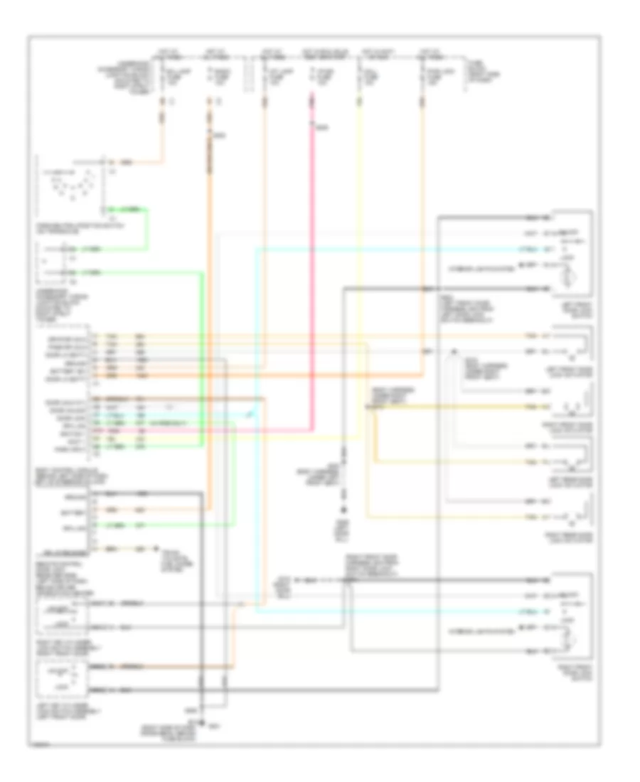
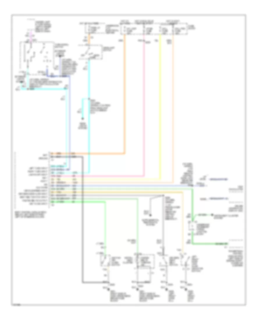
AIR CONDITIONING
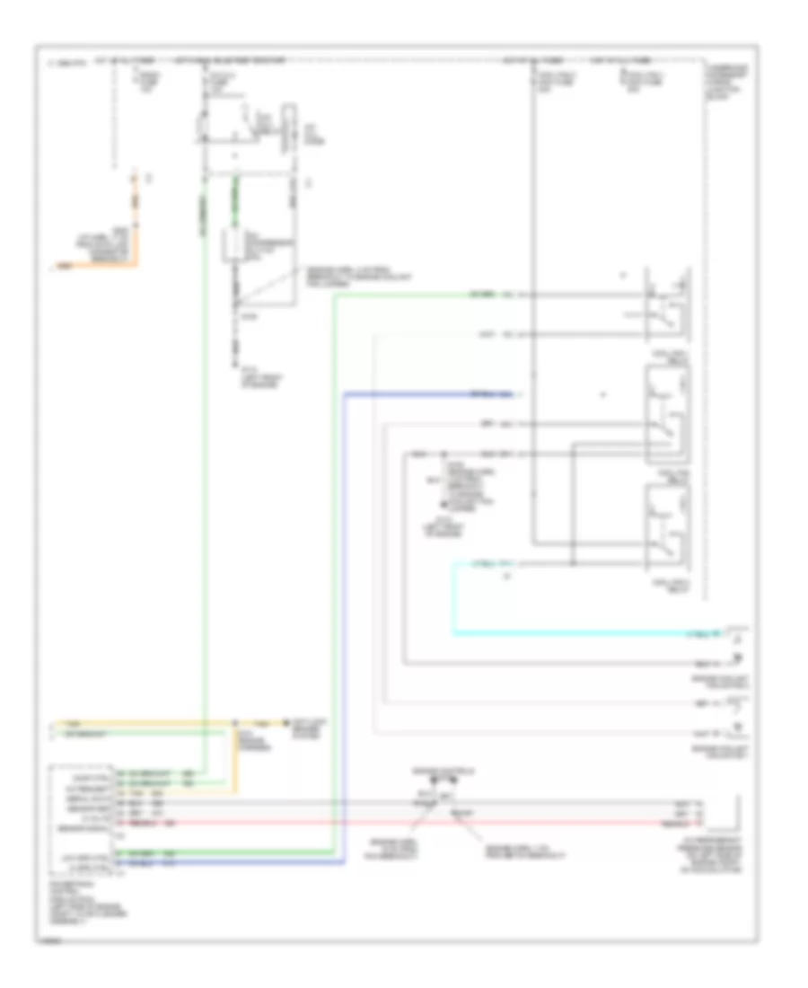
A/C Wiring Diagram, Auto A/C (1 of 2) for Pontiac Grand Prix GTP 1998
 https://portal-diagnostov.com/license.html
Automotive Electricians Portal FZCO
Automotive Electricians Portal FZCO
https://portal-diagnostov.com/license.html
https://portal-diagnostov.com/license.html
Automotive Electricians Portal FZCO
Automotive Electricians Portal FZCO
List of elements for A/C Wiring Diagram, Auto A/C (1 of 2) for Pontiac Grand Prix GTP 1998:
- (i/p harn, 4 cm from blower motor control mod breakout)
- (i/p harn, 11 cm from data link connector breakout)
- (i/p harn, 37 cm from data link connector breakout)
- (i/p harn, 43 cm from data link connector breakout)
- (i/p harness, 4 cm from blower motor control module breakout)
- (i/p harness, 4 cm from breakout to data link connector)
- (right side of dash)
- (right side of dash) g201
- +5 v
- 5 volts
- A/c request
- A/c sol ctrl
- A/c solenoid
- Ambient outside air temperature sensor (behind front panel, mount to radiator baffle)
- Battery
- Bi-lev sol ctrl
- Bi-level solenoid
- Blower motor
- Blower motor control module (in right side of heater-a/c module)
- C 1995 vftc
- C10
- C11
- C12
- C13
- C14
- C15
- C16
- Connected w/ metric display
- D10
- D11
- D12
- D13
- D14
- D15
- D16
- Data link (dlc) connector (under left side of dash, right side of steering column)
- Def sol ctrl
- Defrost solenoid
- Dic/hvac fuse 10a
- Eng/metric
- Fuse block
- G201
- G201 (right side of dash)
- Ground
- Heater and a/c control
- Heater solenoid
- Hot at all times
- Hot in run
- Htr sol ctrl
- Hvac hi fuse 30a
- Ignition
- Inside air temperature sensor (front of dash, below right side of instrument cluster)
- Inside temp input
- Left electric actuator (left side of heater- a/c module)
- Motor drive
- Nca
- Outside temp input
- Rear defog enable
- Rear defogger system
- Recirc sol ctrl
- Recirc solenoid
- Red
- Right electric actuator (right side of heater- a/c module)
- S206
- S211
- S213
- S237 (i/p harn, 30 cm from data link connector breakout)
- S245
- S258
- Sensor ground
- Serial data
- Solid state
- Sun load input
- Sun load temperature sensor (top center of dash)
- Tan
- Vacuum/ electric solenoid (on right side of heater-a/c module)
- Volt to blw ctrl
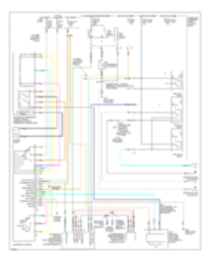
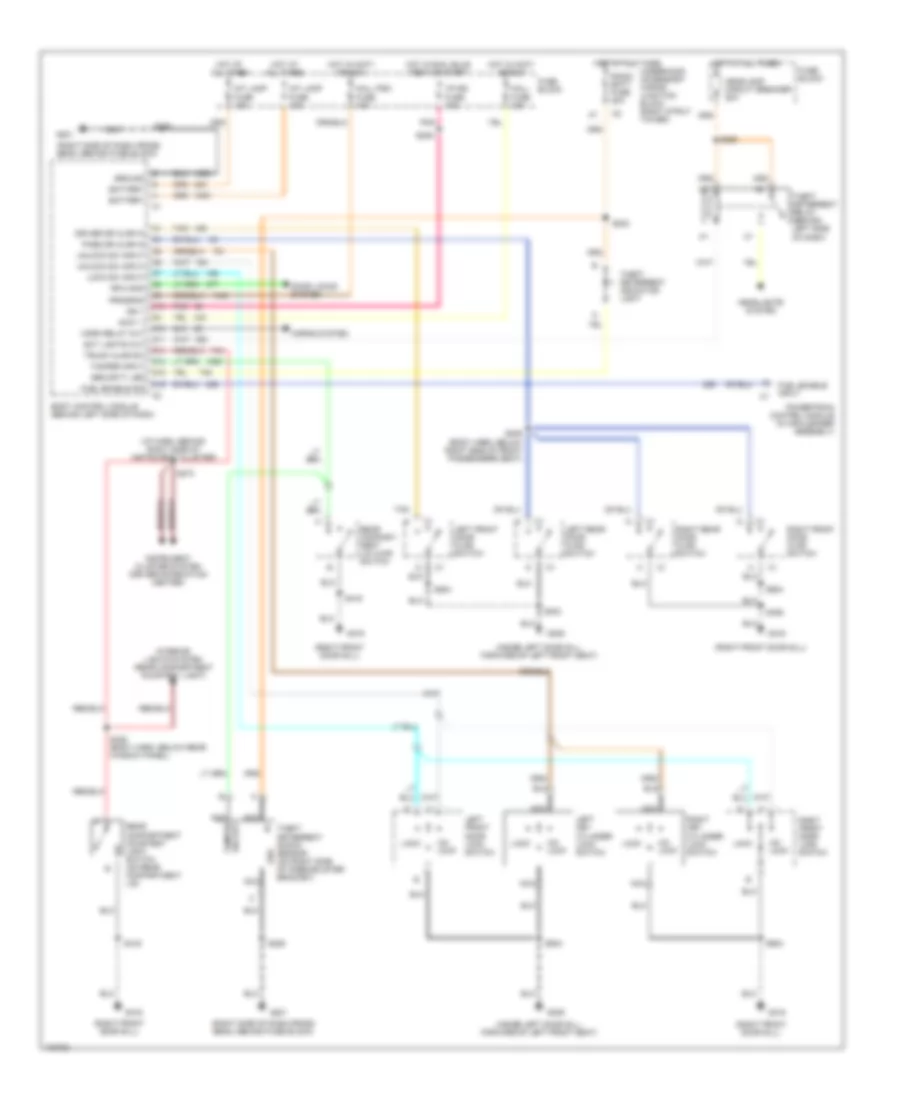
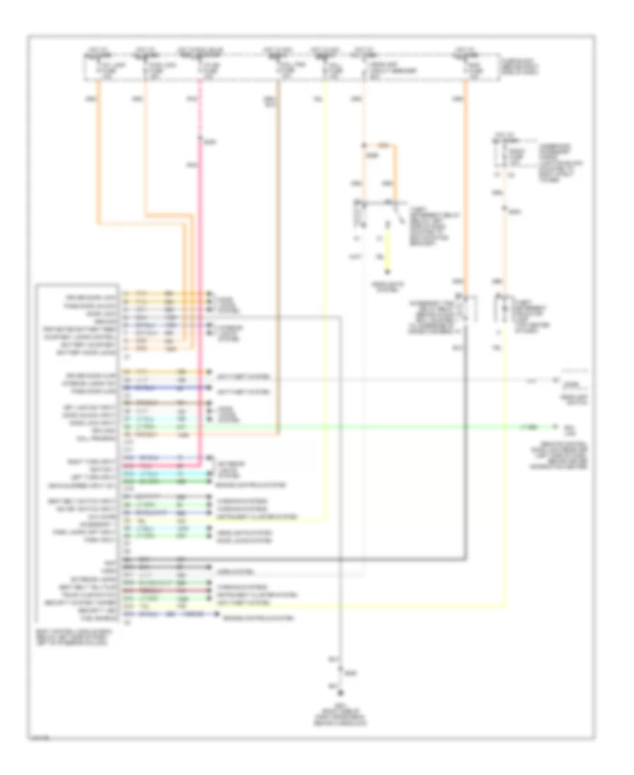
A/C Wiring Diagram, Auto A/C (2 of 2) for Pontiac Grand Prix GTP 1998
List of elements for A/C Wiring Diagram, Auto A/C (2 of 2) for Pontiac Grand Prix GTP 1998:
- (engine harn, 15 cm from pcm breakout)
- (engine harn, 4 cm from breakout to engine coolant fan jumper)
- (engine harn, 7 cm from ebtcm breakout)
- 5 volts
- A/c clu diode
- A/c clu fuse 10a
- A/c clu relay
- A/c compressor clutch coil
- A/c refrigerant pressure sensor (on left side of engine compt, on accumulator)
- A/c request
- A10
- Anti-lock brakes system
- C 1995 vftc
- C10
- C11
- Comp ctrl
- Cool fan 1 maxi fuse 30a
- Cool fan 1 relay
- Cool fan 2 maxi fuse 30a
- Cool fan 2 relay
- Cool fan relay
- Engine controls system
- Engine coolant fan motor 1
- Engine coolant fan motor 2
- F11
- G110 (left front of engine)
- Hi spd ctrl
- Hot at all times
- Hot in run, bulb test or start
- Low spd ctrl
- Powertrain control module (pcm) (left side of engine compt, in air cleaner assembly)
- Radio fuse 10a
- S105
- S105 (engine harn, 4 cm from breakout to engine coolant fan jumper)
- S122
- S131 (engine harness)
- S167
- S202 (i/p harn, 17 cm from data link connector breakout)
- Sensor grd
- Sensor signal
- Serial data
- Tan
- Underhood accessory wiring junction block
A/C Wiring Diagram, Manual A/C for Pontiac Grand Prix GTP 1998
List of elements for A/C Wiring Diagram, Manual A/C for Pontiac Grand Prix GTP 1998:
- (eng harn, 15 cm from pcm breakout)
- (engine harn, 4 cm from breakout to engine coolant fan jumper)
- (engine harness, 7 cm from ebtcm breakout)
- (i/p harn, 17 cm from breakout to dlc)
- (i/p harn, 4 cm from breakout to dlc)
- 5 volts
- A nca
- A/c clu diode
- A/c clu relay
- A/c clu/ abs ign fuse 10a
- A/c compressor clutch coil
- A/c refrigerant pressure sensor (on left side of engine compt, on accumulator)
- A/c request sig
- A10
- Battery
- Bi-level
- Blend
- Blower motor
- Blower motor relay
- Blower motor resistor (in right side of heater-a/c module, under right side of dash)
- C10
- C11
- Clutch req
- Comp ctrl
- Cool fan 1 maxi fuse 30a
- Cool fan 1 relay
- Cool fan 2 maxi fuse 30a
- Cool fan 2 relay
- Cool fan relay
- Def
- Def mode
- Defogger on
- Defogger system
- Dic/hvac fuse 10a
- Engine controls system
- Engine coolant fan motor 1
- Engine coolant fan motor 2
- F11
- Fan off input
- Fan on
- Fuse block
- G110 (left front of engine)
- G201 (right side of dash)
- Ground
- Heat
- Heater-a/c control
- Hi spd ctrl
- Hot at all times
- Hot in run
- Hot in run, bulb test or start
- Hvac ctrl fuse 20a
- Hvac hi fuse 30a
- Ignition
- Interior lights
- Interior lights system
- Left electric actuator (left side of heater-a/c module)
- Left temp vlv
- Low spd ctrl
- Max
- Max mode
- Nca
- Off
- Powertrain control module (pcm) (left side of engine compt, in air cleaner assembly)
- Radio fuse 10a
- S105
- S105 (engine harn, 4cm from breakout to engine coolant fan jumper)
- S122
- S167
- S202
- S206
- S213 (i/p harness, 4 cm from blower motor resistor breakout)
- Sensor grd
- Sensor sig
- Tan
- Underhood accessory wiring junction block
- Vent
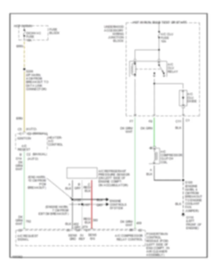
Compressor Wiring Diagram for Pontiac Grand Prix GTP 1998
List of elements for Compressor Wiring Diagram for Pontiac Grand Prix GTP 1998:
- (auto)
- (eng harn, 15 cm from pcm breakout)
- (engine harn, 7 cm from ebtcm breakout)
- (manual) c2
- 5v ref
- A/c clu diode
- A/c clu fuse 10a
- A/c clu relay
- A/c compressor clutch coil
- A/c compressor relay control
- A/c refrigerant pressure sensor (on left side of engine compt, on accumulator)
- A/c reqest
- A/c request signal
- C11
- Dic/hvac fuse 10a
- Engine controls system
- Fan jumper)
- Fuse block
- G110 (left front of engine)
- Heater- a/c control
- Hot in run
- Hot in run, bulb test or start
- Ignition
- Powertrain control module (pcm) (left side of eng compt, in air cleaner assembly)
- S122
- S167
- S206 (i/p harn, 4 cm from breakout to data link connector)
- Sens grd
- Sens sig
- Underhood accessory wiring junction block
ANTI-LOCK BRAKES
Anti-lock Brake Wiring Diagrams for Pontiac Grand Prix GTP 1998
List of elements for Anti-lock Brake Wiring Diagrams for Pontiac Grand Prix GTP 1998:
- (base of steering column) g202
- (engine harn, 4 cm from ebtcm breakout)
- (i/p harn, near cluster)
- (on brake pedal bracket)
- A/c clu/ abs ign fuse 10a
- Abs ind
- Anti-lock wanring ind
- B c1
- Battery
- Brake pressure modulator valve
- C 1995 vftc
- Check tire press ind
- Connector (right of steering column)
- Data link
- Driver information display
- Electronic brake and traction control module (left side of engine compt)
- Electronic power steering system
- Fuse block
- G102 (left front strut tower)
- Ground
- Hot at all times
- Hot in run, bulb test or start
- Ignition
- Ind ctrl
- Instrument cluster
- Ip-ign fuse 10a
- Left front wheel speed sensor
- Left rear wheel speed sensor
- Lf whl spd
- Lo trac ind
- Low tire pres
- Low trac ind
- Lr whl spd
- Msva high
- Msva low
- Nca
- Pnk
- Powertrain control module (left front of engine compt)
- Pump motor
- Pump mtr ctrl
- Red
- Req tps sig
- Rf whl spd
- Right front wheel speed sensor
- Right rear wheel speed sensor
- Rr whl spd
- S131
- S200
- S205 (i/p harn, below dash)
- S209
- S276
- S278
- S280
- Serial data
- Stop lamp fuse 15a
- Stop lamp switch
- Stop lp feed
- Tach out c2
- Tach signal
- Tan
- Tcs ind
- Tcs signal
- Tire infl reset
- Torque del c2
- Torque req c1
- Trac ctrl
- Trac off ind
- Trac switch
- Trip calculator
- Underhood accessory wiring junction block
- W/ driver information display
- W/ trip calculator
- Warning systems
ANTI-THEFT
Anti-theft Wiring Diagram for Pontiac Grand Prix GTP 1998
List of elements for Anti-theft Wiring Diagram for Pontiac Grand Prix GTP 1998:
- (i/p harn, behind right side of instrument cluster)
- (inside left door sill, forward of left front seat)
- (right front door sill)
- (right side of dash cross beam, behind fuse block)
- Accy 1
- Battery
- Body control module (behind left side of dash)
- C13
- D10
- D11
- D13
- D14
- D15
- D16
- Door locks system
- Driver dr ajar in
- Ext lights out
- Fuel enable input
- Fuel enable sig
- Fuse block
- G201
- G309
- G316
- Grd
- Ground
- Headlamp circuit breaker 20a
- Headlights system
- Horn relay out
- Horns system
- Hot at all times
- Hot in accy or run
- Hot in run, bulb test or start
- I/p-ign fuse 10a
- Ign 1
- Instrument cluster system (driver information center)
- Int lamp fuse 10a
- Interior lights system (rear compartment courtesy light)
- Left front door ajar switch
- Left front door lock switch
- Left key cylinder lock switch
- Left rear door ajar switch
- Lock
- Lock sw input
- Mall fuse 10a
- Mall pgm fuse 10a
- Nca
- Pass dr ajar in
- Pnk
- Powertrain control module (in air cleaner assembly)
- Program
- Radio batt fuse 20a
- Rear compart- ment lid ajar switch
- Rear compartment courtesy light switch (on rear compartment lid)
- Rfa cmdi
- Right front door ajar switch
- Right front door lock switch
- Right key cylinder lock switch
- Right rear door ajar switch
- S202
- S209
- S265
- S273
- S285
- S303
- S309 (body harn, below right side of front passenger's seat)
- S406
- S416
- S428 (body harn, below rear window panel)
- S504
- S604
- Security led
- Tamper input
- Tamper sig out
- Tan
- Theft deterrent indicator light
- Theft deterrent relay (behind left side of dash)
- Theft deterrent shock sensor (on right side of knee bolster bracket)
- Trunk ajar sw
- Un- lock
- Underhood accessory wiring junction block (right strut tower)
- Unlock sw input
BODY COMPUTER
Body Computer Wiring Diagrams for Pontiac Grand Prix GTP 1998
List of elements for Body Computer Wiring Diagrams for Pontiac Grand Prix GTP 1998:
- (1998-99)
- Accessory 1
- Accessory time delay relay (behind glove box, mounted to underside of cross car beam)
- Anti-theft system
- Aux chime
- Battery courtesy
- Battery door locks
- Body control module (bcm) (below left side of dash, left of steering column)
- C10
- C11
- C12
- C13
- C14
- C15
- C16
- Courtesy lamps control
- D10
- D11
- D12
- D13
- D14
- D15
- D16
- Dome
- Door lock
- Door lock input
- Door locks system
- Door unlock input
- Driver door ajar
- Driver door lock
- Engine controls system
- Exterior lamps
- Exterior lights system
- Fuel enable
- Fuse block (behind right side of dash)
- G201 (right side of dash cross beam, behind fuse block)
- Ground
- Headlamp circuit breaker 20a
- Headlamp switch
- Headlights system
- Horn
- Horn system
- Hot at all times
- Hot in acc or run
- Hot in run, bulb test, or start
- I/p ign fuse 10a
- Ign key switch input
- Ignition 1
- Instrument cluster system
- Int lamp fuse 10a
- Interior lamps "on"
- Interior lights system
- Key lock sw input
- Left turn input
- Mall fuse 10a
- Mall pgm fuse 10a
- Mall program
- Park input
- Park lamps "off" input
- Pass door ajar
- Pass door unlock
- Pnk
- Protected battery feed
- Pwr lock fuse 15a
- Radio fuse 10a
- Rap
- Rap fuse 10a
- Remote control door lock receiver (left side of dash, behind driver information center)
- Rfa cmdi
- Rfa link
- Right turn input
- S202
- S209
- S265
- S285
- Seat belt switch input
- Seat belt telltale
- Security led
- Security system tamper
- Tan
- Theft deterrent indicator lamp (top center of dash)
- Theft deterrent relay (below left side of dash, mounted to bcm mounting bracket)
- Trunk ajar switch
- Underhood accessory wiring junction block (mounted to right strut tower)
- Vehicle speed input (5v)
- Warning systems
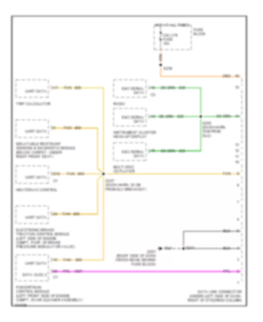
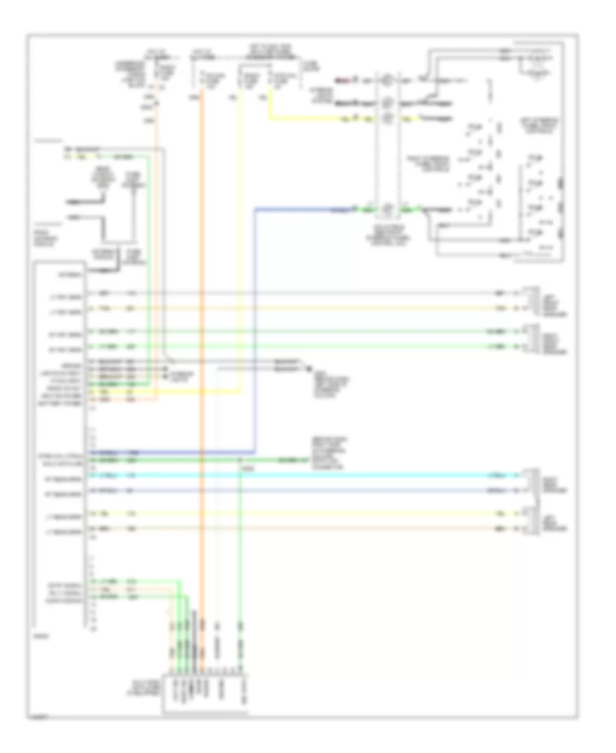
COMPUTER DATA LINES
Computer Data Lines for Pontiac Grand Prix GTP 1998
List of elements for Computer Data Lines for Pontiac Grand Prix GTP 1998:
- Cig ltr fuse 15a
- D12
- Data clss 2
- Data link connector (under left side of dash, right of steering column)
- E&c serial data
- Electronic brake/ traction control module (left side of engine compt, part of brake pressure modulator valve)
- Fuse block
- G201 (right side of dash cross beam, behind fuse block)
- Heater-a/c control
- Hot at all times
- Inflatable restraint sensing & diagnostic module (below carpet, under right front seat)
- Instrument cluster head-up display
- Multi disc cd player
- Powertrain control module (left front side of engine compt, in air cleaner assembly)
- Radio
- S211
- S225 (dash harn, 5cm from dlc)
- S237 (dash harn, 30 cm from dlc breakout)
- S238
- Tan
- Trip calculator
- Uart data
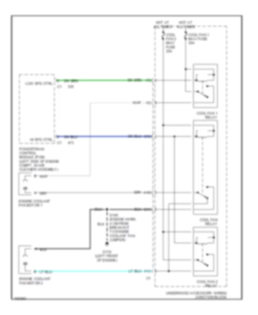
COOLING FAN
Cooling Fan Wiring Diagram for Pontiac Grand Prix GTP 1998
List of elements for Cooling Fan Wiring Diagram for Pontiac Grand Prix GTP 1998:
- A10
- All times
- C10
- C11
- Cool fan 2 maxi fuse 30a
- Cool fan 1 maxi fuse 30a
- Cool fan 1 relay
- Cool fan 2 relay
- Cool fan relay
- Engine coolant fan motor 1
- Engine coolant fan motor 2
- F11
- G110 (left front of engine)
- Hi spd ctrl
- Hot at
- Low spd ctrl
- Powertrain control module (pcm) (left side of engine compt, in air cleaner assembly)
- S105 (engine harn, 4 cm from breakout to engine coolant fan jumper)
- Underhood accessory wiring junction block
CRUISE CONTROL
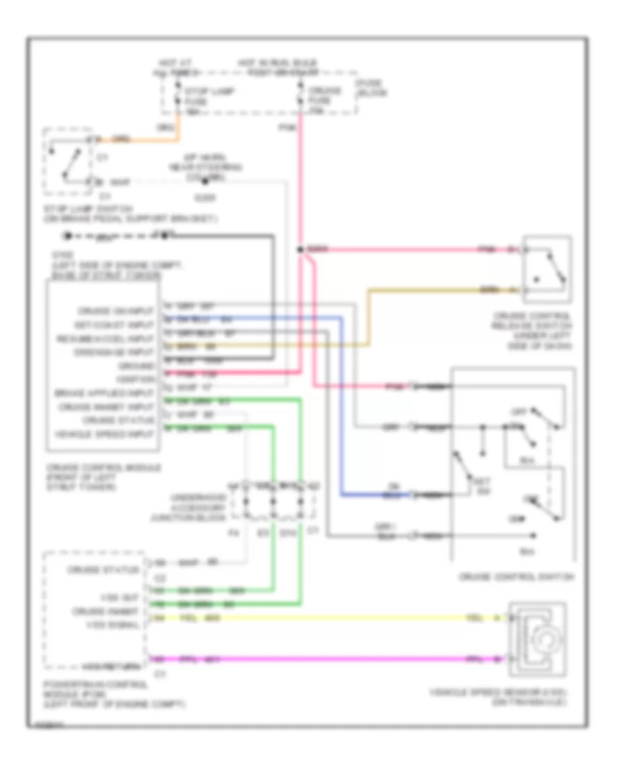
Cruise Control Wiring Diagram for Pontiac Grand Prix GTP 1998
List of elements for Cruise Control Wiring Diagram for Pontiac Grand Prix GTP 1998:
- (i/p harn, near steering column)
- All times
- B10
- Cruise control module (front of left strut tower)
- Cruise control release switch (under left side of dash)
- Cruise control switch
- Cruise fuse 10a
- Cruise inhibit
- Cruise inhibit input
- Cruise on input
- Cruise status
- D10
- Disengage input
- Fuse block
- G102 (left side of engine compt, base of strut tower)
- Ground
- Hot at
- Hot in run, bulb
- Ignition
- Nca
- Off
- Pnk
- Powertrain control module (pcm) (left front of engine compt)
- R/a
- Resume/accel input
- S125
- S205
- S266
- Set sw
- Set/coast input
- Stop lamp fuse 15a
- Stop lamp switch (on brake pedal support bracket)
- Test or start
- Underhood accessory junction block
- Vehicle speed input
- Vehicle speed sensor (vss) (on transaxle)
- Vss out
- Vss return
- Vss signal
DEFOGGERS
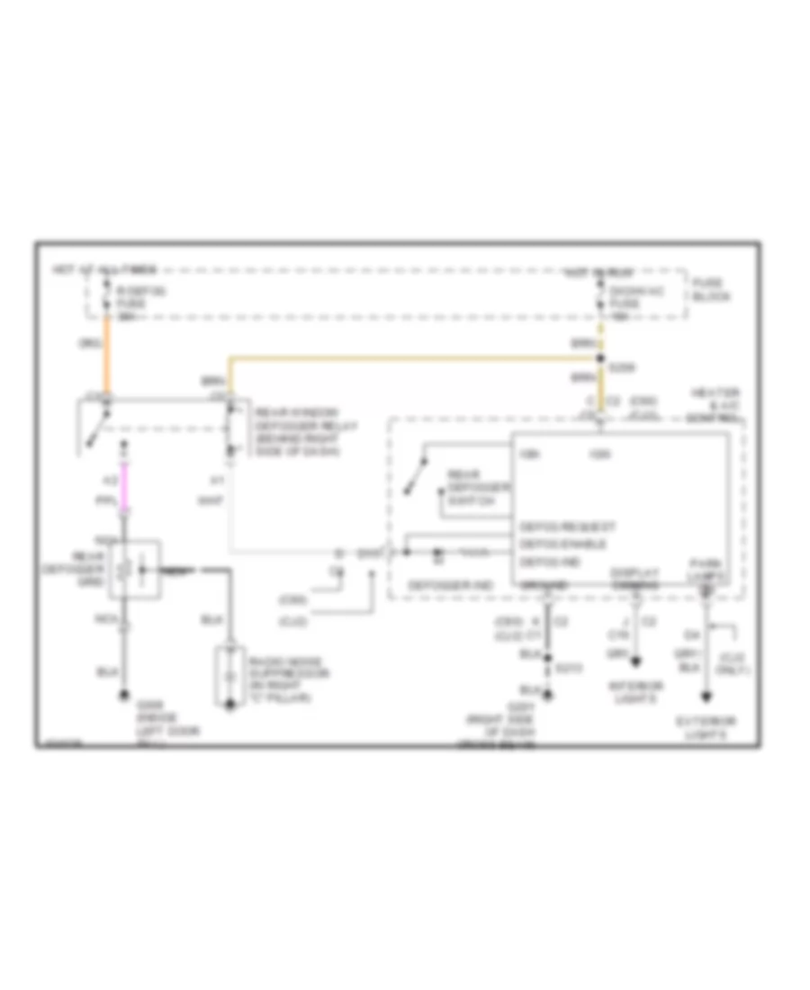
Defogger Wiring Diagram for Pontiac Grand Prix GTP 1998
List of elements for Defogger Wiring Diagram for Pontiac Grand Prix GTP 1998:
- (c60)
- (c60) (cj2)
- (cj2 only)
- (cj2)
- C c2
- C16
- D15
- Defog enable
- Defog ind
- Defog request
- Defogger ind
- Dic/hvac fuse 10a
- Display dimming
- Exterior lights
- Fuse block
- G201 (right side of dash cross beam)
- G309 (inside left door sill)
- Ground
- Heater & a/c control
- Hot at all times
- Hot in run
- Ign
- Interior lights
- J c2
- K c2
- Nca
- Park lamps on
- R defog fuse 30a
- Radio noise suppressor (in right "c" pillar)
- Rear defogger grid
- Rear defogger switch
- Rear window defogger relay (behind right side of dash)
- S206
- S213
ELECTRONIC POWER STEERING
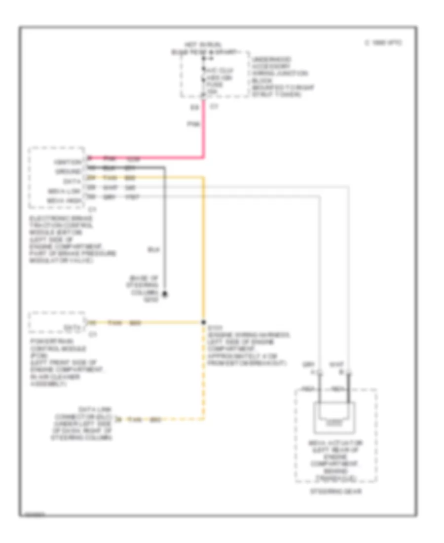
Electronic Power Steering Wiring Diagram for Pontiac Grand Prix GTP 1998
List of elements for Electronic Power Steering Wiring Diagram for Pontiac Grand Prix GTP 1998:
- (base of steering column) g202
- 1995 vftc c
- A/c clu/ abs ign fuse 10a
- Data
- Data link connector (dlc) (under left side of dash, right of steering column)
- Electronic brake traction control module (ebtcm) (left side of engine compartment, part of brake pressure modulator valve)
- Ground
- Hot in run, bulb test & start
- Ignition
- Msva actuator (left rear of engine compartment, behind transaxle)
- Msva high
- Msva low
- Nca
- Pnk
- Powertrain control module (pcm) (left front side of engine compartment, in air cleaner assembly)
- S131 (engine wiring harness, left side of engine compartment, approximately 4 cm from ebtcm breakout)
- Steering gear
- Tan
- Underhood accessory wiring junction block (mounted to right strut tower)
ENGINE PERFORMANCE
3.1L
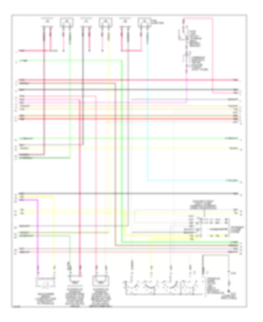
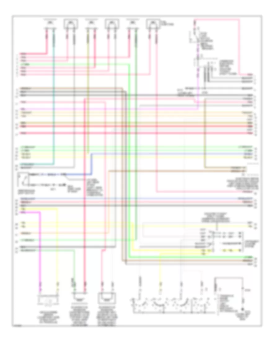
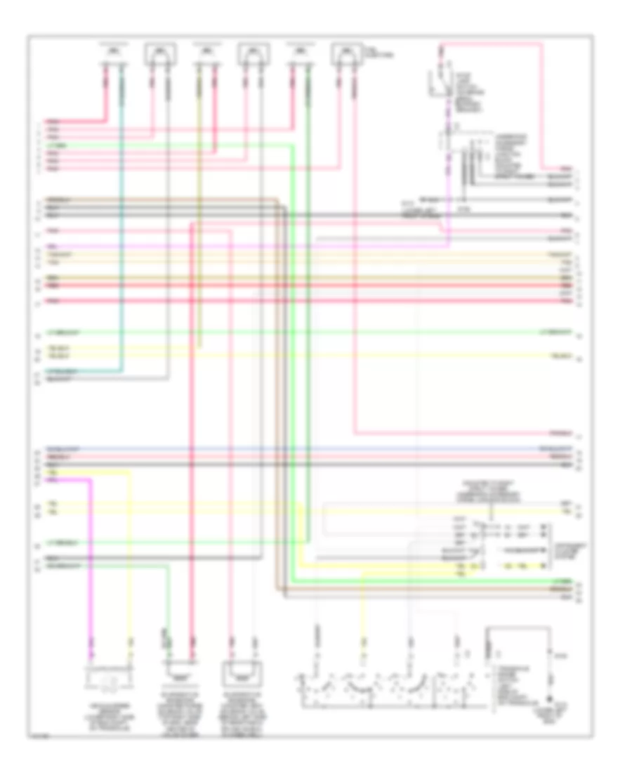
3.1L (VIN M), Engine Performance Wiring Diagrams (1 of 4) for Pontiac Grand Prix GTP 1998
List of elements for 3.1L (VIN M), Engine Performance Wiring Diagrams (1 of 4) for Pontiac Grand Prix GTP 1998:
- (eng harn, on right side of eng compt, 15 cm from pcm breakout)
- (lower left front of eng)
- (pin 10-12 not used)
- (pin 21-27 not used)
- (pin 39-42 not used)
- (pin 49-52 not used)
- (pin 62-63 not used)
- 1-2 ss valve control
- 2-3 ss valve control
- 3x ref high
- 3x ref low (ground)
- A12
- Anti-theft system
- Bypass control
- C10
- Camshaft position sensor (front of eng, below intake plenum)
- Canister vent fuse 10a
- Charge ind control
- Ckp sensor signal
- Cmp signal
- Cooling fan system
- Crankshaft position sensor (24x) (front of eng, behind harmonic balancer)
- Crankshaft position sensor (7x) (lower right side of of eng, below exhaust manifold)
- Cruise control system
- Cruise disable output
- D11
- Data link connector (under left side of dash, right of steering column)
- Dfi fuse 15a
- Ecm fuse 10a
- Ecm sense fuse 10a
- Egr val control (gnd)
- Evap purge val drviver
- Fuel inj #1 driver
- Fuel inj #2 driver
- Fuel inj #3 driver
- Fuel inj #5 driver
- Fuel inj #6 driver
- Fuel level level ctrl
- Fuse block (behind right side of dash, in right door opening)
- G110
- G11o
- High speed fans control
- Hos1 low
- Hos2 low
- Hot at all times
- Hot coolant ind control
- Hot in off, run bulb test, or start
- Hot in run, bulb test or start
- Iac coil b high
- Iat sensor ground
- Ic control
- Ign1-uh fuse 15a
- Ignition control module (top right side of eng)
- Ignition wake up power
- Inj fuse 10a
- Instrument cluster system
- Knock sensor (left side of eng, above starter)
- Knock sensor signal
- Low speed fans control
- Maf sensor signal
- Map/ect sensor signal
- Nca
- Pcm ground
- Pnk
- Pnk b
- Power (battery)
- Powertrain control module (left front side of eng compt, in air cleaner assembly)
- Red
- S106
- S131
- S146
- S155
- Sensor ground
- Serial data (class 2)
- Serial data (uart)
- Spark plugs
- Starting/ charging system
- Tan
- Tcc brake switch input
- Theft deter fuel enable
- Tp sensor signal
- Tr switch input b
- Underhood accessory wiring junction block (mounted to right strut tower)
- Vss high
- Vss low
- Vss output
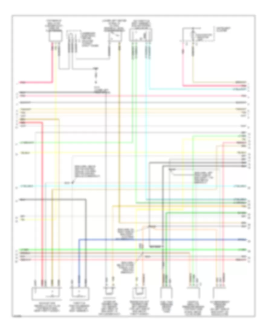
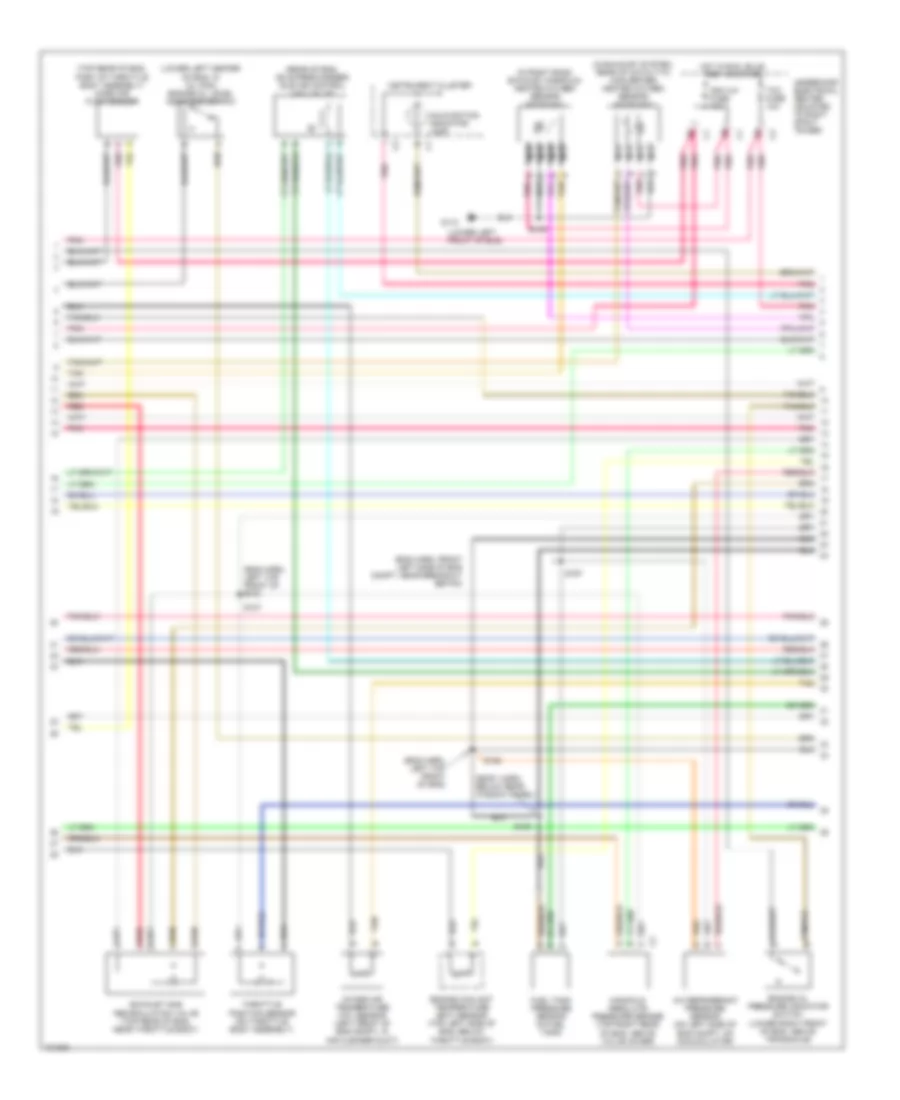
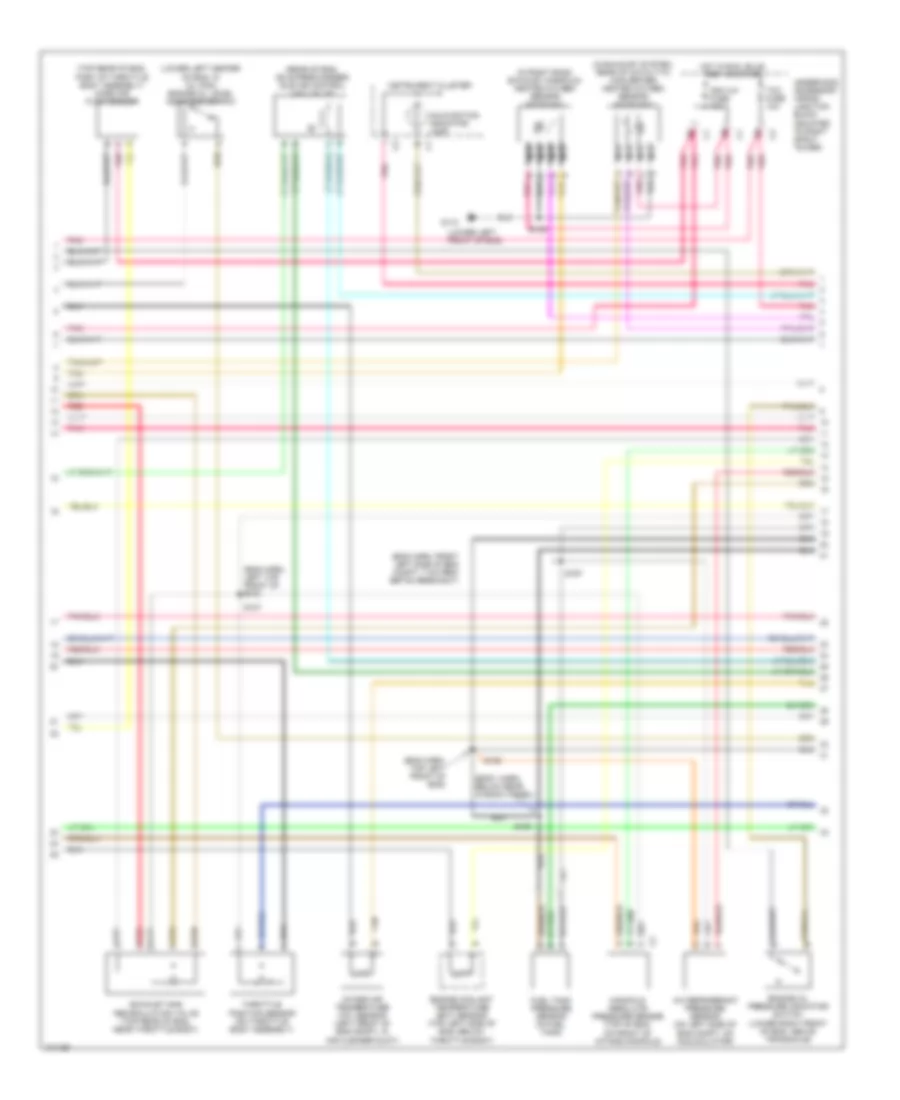
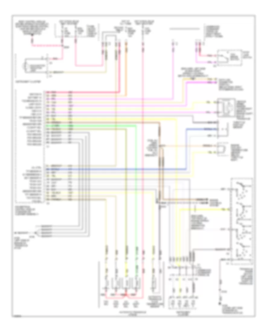
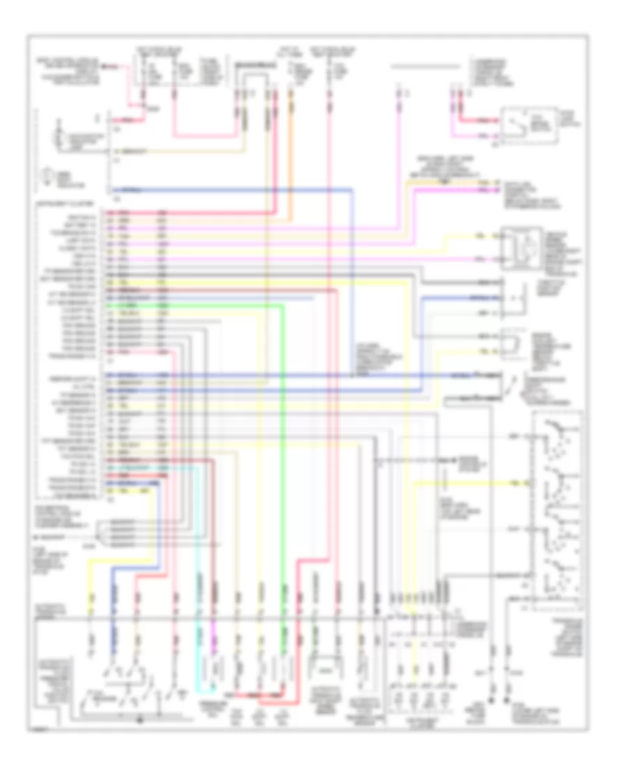
3.1L (VIN M), Engine Performance Wiring Diagrams (2 of 4) for Pontiac Grand Prix GTP 1998
List of elements for 3.1L (VIN M), Engine Performance Wiring Diagrams (2 of 4) for Pontiac Grand Prix GTP 1998:
- (lower left front of eng)
- (mounted to right strut tower) underhood accessory wiring junction block)
- A12
- Evaporative emissions canister purge solenoid valve (top right side of eng, behind ignition control module)
- Evaporative emissions canister vent solenoid valve (behind left side of rear fascia splash shield, behind wheelwell)
- F12
- Fuel injectors
- G110
- Instrument cluster system
- Pnk
- Red
- S105
- S109
- Stop lamp switch (on brake pedal support c2 bracket)
- Tan
- Transaxle range switch (left side of eng compt, on transaxle)
- Underhood electrical center (mounted to right strut tower)
- Vehicle speed sensor (lower right side of eng compt, on transaxle)
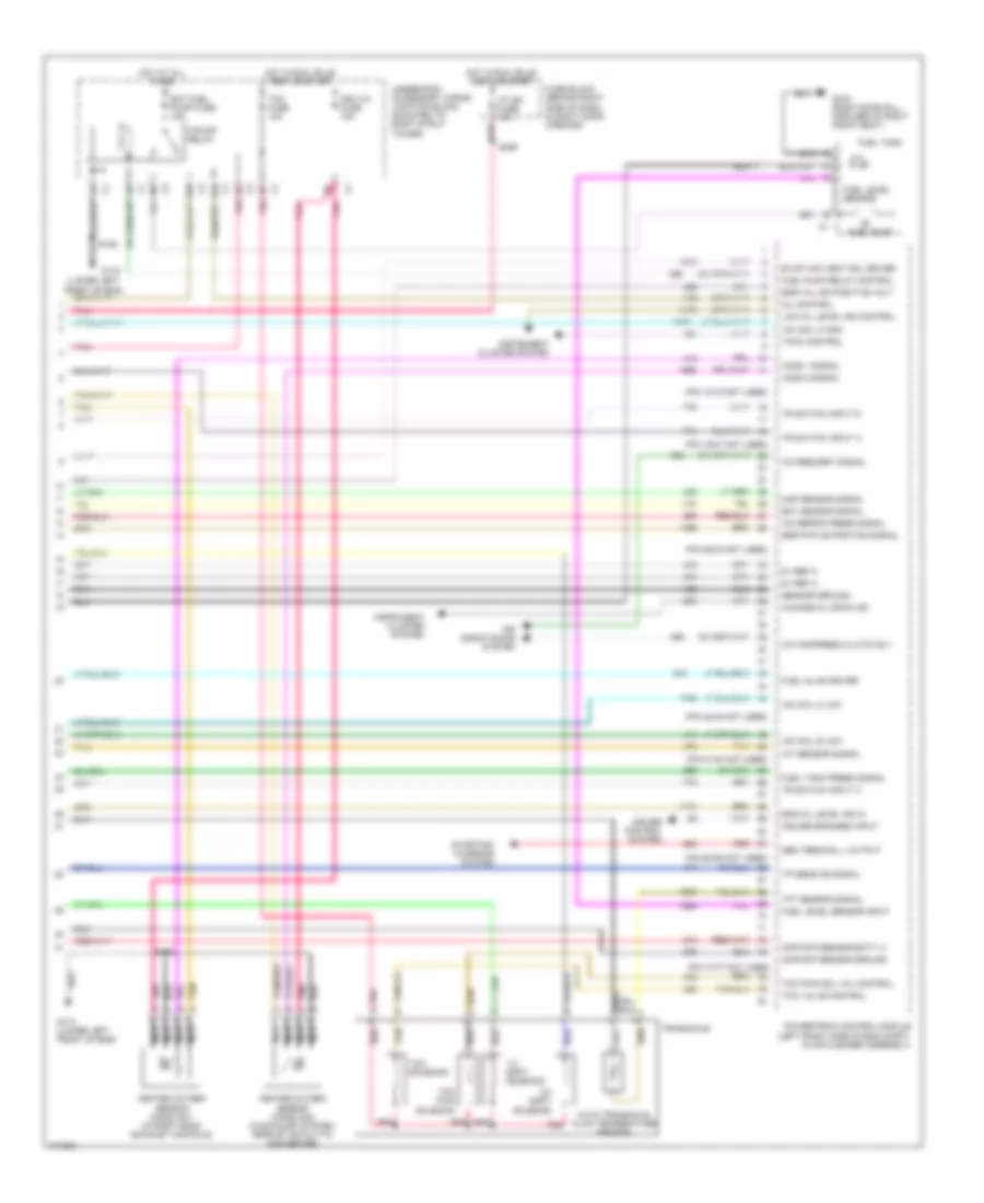
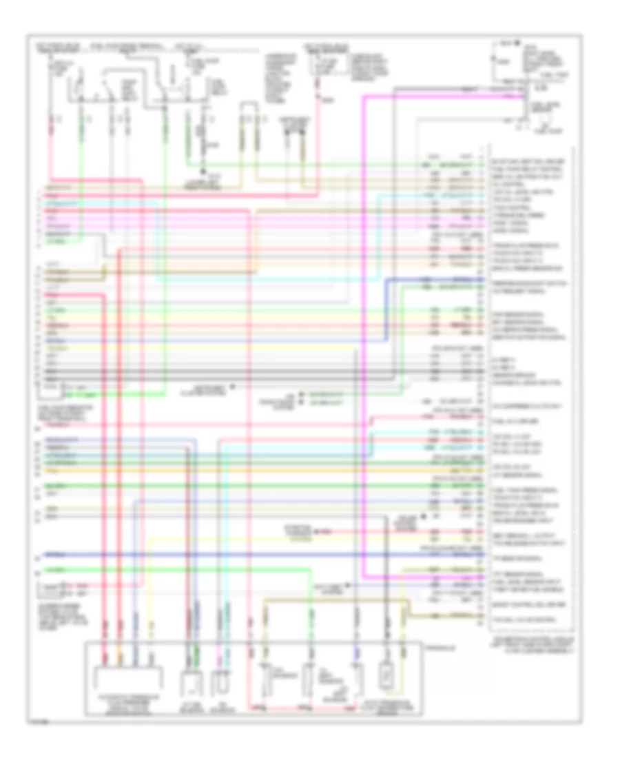
3.1L (VIN M), Engine Performance Wiring Diagrams (3 of 4) for Pontiac Grand Prix GTP 1998
List of elements for 3.1L (VIN M), Engine Performance Wiring Diagrams (3 of 4) for Pontiac Grand Prix GTP 1998:
- (eng harn, above ignition control module, 2 cm from ignition control module c2 breakout)
- (eng harn, below intake plenum, 2 cm from pcm breakout)
- (eng harn, left front side of eng compt, 7 cm from ebtcm breakout)
- (eng harn, on right side of eng compt, 15 cm from pcm breakout)
- (lower left center of eng, in oil pan) engine oil level indicator switch
- (on throttle body assembly) idle air control (iac) valve
- (top rear of eng, in air cleaner duct) mass air flow sensor
- A/c refrigerant pressure sensor (on left side of eng compt, on accumulator)
- Engine coolant temperature (ect) sensor (top left side of eng, below throttle body)
- Exhaust gas recirculation valve (top rear of eng, near throttle body)
- Fuel tank pressure sensor (in fuel tank)
- G110 (lower left front of eng)
- Instrument cluster
- Intake air temperature (iat) sensor (left front of eng compt, in air cleaner duct)
- Malfunction indicator lamp
- Manifold absolute pressure sensor (top right side of eng, above valve cover)
- Pnk
- Red
- S106
- S107
- S121
- S122
- S167
- S409
- Tan
- Throttle position sensor (on throttle body assembly)
- Underhood electrical center (mounted to right strut tower)
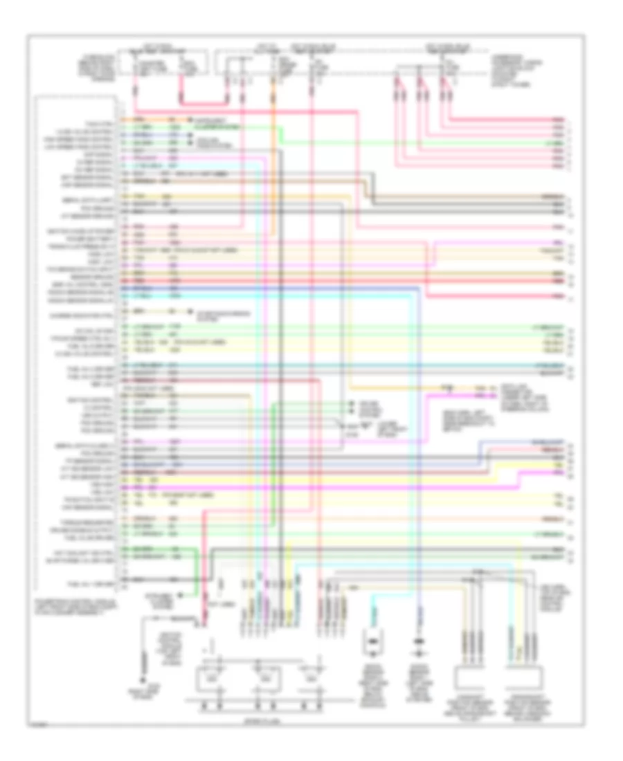
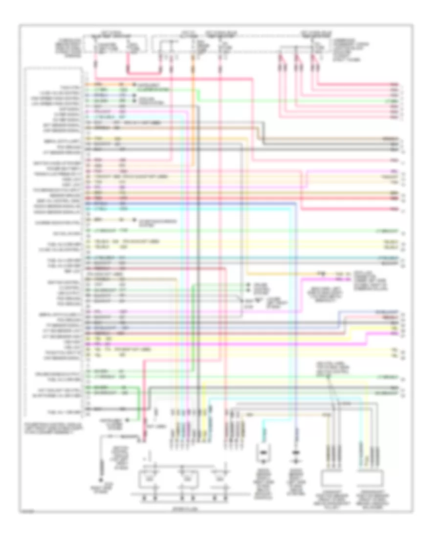
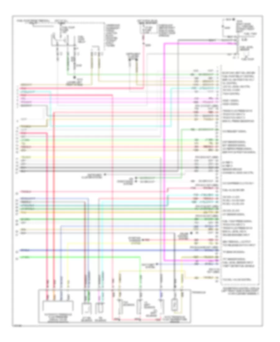
3.1L (VIN M), Engine Performance Wiring Diagrams (4 of 4) for Pontiac Grand Prix GTP 1998
List of elements for 3.1L (VIN M), Engine Performance Wiring Diagrams (4 of 4) for Pontiac Grand Prix GTP 1998:
- (lower left front of eng)
- (pin 12-15 not used)
- (pin 19-21 not used)
- (pin 29-32 not used)
- (pin 45-48 not used)
- (pin 51-54 not used)
- (pin 62-65 not used)
- (pin 74-77 not used)
- (right door sill, forward of right front seat)
- 1-2 shift solenoid
- 2-3 shift solenoid
- 5v ref a
- A/c compress clutch rly
- A/c refrig press signal
- A/c request signal
- Air conditioning system
- Auto transaxle fluid temperature sensor
- B10
- Bat fuel pump fuse 15a
- Change oil soon ind
- Cmp/ckp sensor batt (+)
- Cmp/ckp sensor ground
- Cruise control system
- Cruise engaged input
- D10
- Ect sensor signal
- Egr pintle position signal
- Egr val ign positive volt
- Eng oil level ind in
- Evap can vent sol driver
- F/pump relay
- Fuel inj #4 driver
- Fuel level sensor
- Fuel level sensor input
- Fuel pump
- Fuel pump relay control
- Fuel tank
- Fuel tank press signal
- Fuse block (behind right side of dash, in right door opening)
- G110
- G110 (lower left front of eng)
- G316
- Gen terminal l output
- Heated oxygen sensor (ho2s) no1 (in right bank exhaust manifold)
- Heated oxygen sensor (ho2s) no2 (in exhaust system, rear of catalytic converter)
- Ho2s 1 signal
- Ho2s 2 signal
- Hot at all times
- Hot in run, bulb test or start
- Hot in run, bulb test, or start
- I/p ign fuse 10a
- Iac coil a high
- Iac coil a low
- Iac coil b low
- Iat sensor signal
- Ign1-uh fuse 15a
- Instrument cluster system
- Low oil level ind control
- Map sensor signal
- Mil control
- Nca
- Pnk
- Pnk e
- Powertrain control module (left front side of eng compt, in air cleaner assembly)
- Red
- S105
- S106
- S209
- Sensor ground
- Starting/ charging system
- Tach control
- Tan
- Tcc fuse 10a
- Tcc pwm sol val control
- Tcc pwm solenoid
- Tcc solenoid
- Tcc valve control
- Tft sensor signal
- Tp sens or signal
- Tr switch input a
- Tr switch input c
- Tr switch input d
- Transaxle
- Underhood accessory wiring junction block (mounted to right strut tower)
3.8L
3.8L (VIN 1), Engine Performance Wiring Diagrams (1 of 4) for Pontiac Grand Prix GTP 1998
List of elements for 3.8L (VIN 1), Engine Performance Wiring Diagrams (1 of 4) for Pontiac Grand Prix GTP 1998:
- (eng harn, left side of eng compt, near breakout to ebtcm)
- (ign harn, top of eng, near ign control module)
- (lower left front of eng)
- (not used)
- (pin 10-11 not used)
- (pin 21 & 23-27 not used)
- (pin 40-42 not used)
- (pin 49-52 not used)
- (pin 66-67 not used)
- (right side of eng)
- 1-2 ss valve control
- 18x ref signal
- 2-3 ss valve control
- 3x ref signal
- A/t iss sensor high
- A/t iss sensor low
- A12
- B12
- C10
- C12
- Camshaft position sensor (front of eng, above crankshaft pulley)
- Canister vent fuse 10a
- Charge indicator ctrl
- Cmp signal
- Cooling fans system
- Crankshaft position sensor (front of eng, behind harmonic balancer)
- Cruise control system
- Cruise disable output
- D11
- Data link connector (under left side of dash, right of steering column)
- Dfi fuse 15a
- Ecm fuse 10a
- Ecm sense fuse 10a
- Ect sensor signal
- Egr val control (gnd)
- Evap purge val drviver
- F/pump speed ctrl rly
- Fuel inj #2 driver
- Fuel inj 1 driver
- Fuel inj 4 driver
- Fuel inj 5 driver
- Fuel inj 6 driver
- Fuse block (behind right side of dash, in right door opening)
- G110
- G120
- High speed fans control
- Hos1 low
- Hos2 low
- Hot at all times
- Hot coolant ind ctrl
- Hot in run bulb test, or start
- Hot in run, bulb test or start
- Iac coil b high
- Iat sensor ground
- Ic control
- Ignition control
- Ignition control module (top left front of eng)
- Ignition wake up power
- Inj fuse 10a
- Instrument cluster system
- Istrument cluster system
- Knock sensor bank 1 (left side of eng, above starter)
- Knock sensor bank 2 (right side of eng, below exhaust manifold)
- Knock sensor signal #1
- Knock sensor signal #2
- Low speed fans control
- Maf sensor signal
- Map sensor signal
- Pcm ground
- Pnk
- Pnk p
- Power (battery)
- Powertrain control module (left front side of eng compt, in air cleaner assembly)
- Red
- Ref low
- S106
- S131
- S144
- S145
- Sensor ground
- Serial data (class ii)
- Serial data (uart)
- Spark plugs
- Starting/charging system
- Tach ctrl
- Tan
- Tcc brake switch input
- Torque requested
- Tp sensor signal
- Tr switch input b
- Trans fluid press sw a
- Underhood accessory wiring junction block (mounted to right strut tower)
- Vss high
- Vss low
- Vss output
3.8L (VIN 1), Engine Performance Wiring Diagrams (2 of 4) for Pontiac Grand Prix GTP 1998
List of elements for 3.8L (VIN 1), Engine Performance Wiring Diagrams (2 of 4) for Pontiac Grand Prix GTP 1998:
- (i/p harn, left rear of eng compt, near breakout to windshield wiper motor)
- (lower left front of eng)
- (mounted to right strut tower) underhood accessory wiring junction block)
- A12
- Electronic brake traction control module (left side of eng compt, part of brake pressure, modulator valve)
- Evaporative emissions canister purge solenoid valve (top right side of eng, near center of valve cover)
- Evaporative emissions canister vent solenoid valve (behind left side of rear fascia splash shield, in wheelwell)
- F12
- Fuel injectors
- G110
- G202 (right side of dash)
- Instrument cluster system
- Nca
- Performance shift switch
- Pnk
- Red
- S105
- S106
- S125
- S211
- Stop lamp switch (on brake pedal
- Support c2 bracket)
- Tan
- Transaxle range switch (left side of eng compt, on transaxle)
- Underhood electrical center (mounted to right strut tower)
- Vehicle speed sensor (lower right side of eng compt, on transaxle)
3.8L (VIN 1), Engine Performance Wiring Diagrams (3 of 4) for Pontiac Grand Prix GTP 1998
List of elements for 3.8L (VIN 1), Engine Performance Wiring Diagrams (3 of 4) for Pontiac Grand Prix GTP 1998:
- (body harn, below rear window panel)
- (eng harn, front left side of eng compt, near breakout ebtcm)
- (eng harn, left top front of eng)
- (in exhaust system, rear of catalytic converter) heated oxygen sensor (ho2s) no2
- (in right bank exhaust manifold) heated oxygen sensor (ho2s) no1
- (lower left center of eng, in oil pan) engine oil level indicator switch
- (lower left front of eng)
- (rear of eng, on supercharger) idle air control (iac) valve
- (top rear of eng, part of throttle body assembly) mass air flow sensor
- A tan
- A/c refrigerant pressure sensor (on left side of eng compt, on accumulator)
- C pnk
- D pnk
- Engine coolant temperature (ect) sensor (top left side of eng, below throttle body)
- Engine oil pressure indicator switch (lower right front of eng, above transaxle)
- Exhaust gas recirculation valve (top rear of eng, near throttle body)
- Fuel tank pressure sensor (in fuel tank)
- G110
- Hot in run, bulb test or start
- Ign1-uh fuse 15a
- Instrument cluster
- Intake air temperature (iat) sensor (left front of eng compt, in air cleaner duct)
- Malfunction indicator lamp
- Manifold absolute pressure sensor (top right rear of eng, above valve cover)
- Nca
- Pnk
- Red
- S105
- S107
- S122
- S167
- S409
- Tan
- Tcc fuse 10a
- Throttle position sensor (on throttle body assembly)
- Underhood electrical center (mounted to right strut tower)
3.8L (VIN 1), Engine Performance Wiring Diagrams (4 of 4) for Pontiac Grand Prix GTP 1998
List of elements for 3.8L (VIN 1), Engine Performance Wiring Diagrams (4 of 4) for Pontiac Grand Prix GTP 1998:
- (fuel pump prime terminal)
- (lower left front of eng)
- (pin 12-15 not used)
- (pin 29-32 not used)
- (pin 40-41 not used)
- (pin 47-48 not used)
- (pin 51-54 not used)
- (pin 62 & 64-65 not used)
- (pin 71-76 not used)
- (right door sill, forward of right front seat)
- (torque delivered
- 1-2 shift solenoid
- 2-3 shift solenoid
- 5v ref a
- A/c compress clutch rly
- A/c refrig press signal
- A/c request signal
- A/t iss solenoid
- Air conditioning system
- Anti-theft system
- Auto transaxle fluid temperature sensor
- Automatic transaxle fluid pressure manual valve position switch
- B10
- Boost control sol driver
- Change oil soon ind ctrl
- Cruise control system
- Cruise engaged input
- D10
- Ect sensor signal
- Egr pintle position signal
- Egr val ign positive volt
- Eng oil level ind in
- Eng oil press sensor sig
- Evap can vent sol driver
- F/pmp spd cont relay
- Fuel inj 3 driver
- Fuel level sensor
- Fuel level sensor input
- Fuel pump
- Fuel pump fuse 15a
- Fuel pump relay
- Fuel pump relay control
- Fuel pump resistor (outside of right front frame rail)
- Fuel tank
- Fuel tank press signal
- Fuse block (behind right side of dash, in right door opening)
- G110
- G316
- Gen terminal l output
- Ho2s 1 signal
- Ho2s 2 signal
- Hot at all times
- Hot in run, bulb test, or start
- I/p ign fuse 10a
- Iac coil a high
- Iac coil a low
- Iac coil b low
- Iat sensor signal
- Ign1-uh fuse 15a
- Instrument cluster system
- Low oil level ind ctrl
- Map sensor signal
- Mil control
- Pc sol valve high
- Pc sol valve low
- Performance shift switch
- Pnk
- Powertrain control module (left front side of eng compt, in air cleaner assembly)
- Ps solenoid
- Red
- S106
- S209
- S406
- Sensor ground
- Starting/ charging system
- Supercharger bypass valve (top rear of eng, above left valve cover)
- Tach control
- Tan
- Tcc release switch input
- Tcc sol valve control
- Tcc solenoid
- Tft sensor signal
- Theft deter fuel enable
- Tp sens or signal
- Tr switch input a
- Tr switch input c
- Tr switch input d
- Trans fluid press sw b
- Transaxle
- Underhood accessory wiring junction block (mounted to right strut tower)
3.8L (VIN K), Engine Performance Wiring Diagrams (1 of 4) for Pontiac Grand Prix GTP 1998
List of elements for 3.8L (VIN K), Engine Performance Wiring Diagrams (1 of 4) for Pontiac Grand Prix GTP 1998:
- (eng harn, left side of eng compt, 4 cm from ebtcm breakout)
- (ign ctrl harn, top of eng, near ignition control module)
- (lower left front of eng)
- (not used)
- (pin 10-11 not used)
- (pin 21 & 23-27 not used)
- (pin 40-42 not used)
- (pin 49-52 not used)
- (pin 66-67 not used)
- (right side of eng)
- 1-2 ss valve control
- 18x ref signal
- 2-3 ss valve control
- 3x ref signal
- A/t iss sensor high
- A/t iss sensor low
- A12
- B12
- C10
- C12
- Camshaft position sensor (front of eng, above crankshaft pulley)
- Canister vent fuse 10a
- Charge indicator ctrl
- Cmp signal
- Cooling fans system
- Crankshaft position sensor (front of eng, behind harmonic balancer)
- Cruise control system
- Cruise disable output
- D11
- Data link connector (under left side of dash, right of steering column)
- Dfi fuse 15a
- Ecm fuse 10a
- Ecm sense fuse 10a
- Ect sensor signal
- Egr val control (gnd)
- Evap purge val drviver
- Fuel inj 1 driver
- Fuel inj 2 driver
- Fuel inj 4 driver
- Fuel inj 5 driver
- Fuel inj 6 driver
- Fuse block (behind right side of dash, in right door opening)
- G110
- G120
- High speed fans control
- Hos1 low
- Hos2 low
- Hot at all times
- Hot coolant ind ctrl
- Hot in run bulb test, or start
- Hot in run, bulb test or start
- Iac coil b high
- Iat sensor ground
- Ic control
- Ignition control
- Ignition control module (top left front of eng)
- Ignition wake up power
- Inj fuse 10a
- Instrument cluster system
- Knock sensor bank 1 (left side of eng, above starter)
- Knock sensor bank 2 (right side of eng, below exhaust manifold)
- Knock sensor signal #1
- Knock sensor signal #2
- Low speed fans control
- Maf sensor signal
- Map sensor signal
- Pcm ground
- Pnk
- Pnk p
- Power (battery)
- Powertrain control module (left front side of eng compt, in air cleaner assembly)
- Red
- Ref low
- S106
- S131
- S144
- S145
- Sensor ground
- Serial data (class ii)
- Serial data (uart)
- Spark plugs
- Starting/charging system
- Tach ctrl
- Tan
- Tcc brake switch input
- Tp sensor signal
- Tr switch input b
- Trans fluid press sw a
- Underhood accessory wiring junction block (mounted to right strut tower)
- Vss high
- Vss low
- Vss output
3.8L (VIN K), Engine Performance Wiring Diagrams (2 of 4) for Pontiac Grand Prix GTP 1998
List of elements for 3.8L (VIN K), Engine Performance Wiring Diagrams (2 of 4) for Pontiac Grand Prix GTP 1998:
- (lower left front of eng)
- (mounted to right strut tower) underhood accessory wiring junction block)
- A12
- Evaporative emissions canister purge solenoid valve (top right side of eng, near center of valve cover)
- Evaporative emissions canister vent solenoid valve (behind left side of rear fascia splash shield, in wheelwell)
- F12
- Fuel injectors
- G110
- Instrument cluster system
- Pnk
- Red
- S105
- S106
- Stop lamp switch (on brake pedal support c2 bracket)
- Tan
- Transaxle range switch (left side of eng compt, on transaxle)
- Underhood accessory wiring junction block (mounted to right strut tower)
- Vehicle speed sensor (lower right side of eng compt, on transaxle)
3.8L (VIN K), Engine Performance Wiring Diagrams (3 of 4) for Pontiac Grand Prix GTP 1998
List of elements for 3.8L (VIN K), Engine Performance Wiring Diagrams (3 of 4) for Pontiac Grand Prix GTP 1998:
- (body harn, below rear window panel)
- (eng harn, front left side of eng compt, 7 cm from ebtcm breakout)
- (eng harn, left top front of eng)
- (eng harn, top left front of eng)
- (in exhaust system, rear of catalytic converter) heated oxygen sensor (ho2s) no2
- (in right bank exhaust manifold) heated oxygen sensor (ho2s) no1
- (lower left center of eng, in oil pan) engine oil level indicator switch
- (lower left front of eng)
- (rear of eng, on supercharger) idle air control (iac) valve
- (top rear of eng, part of throttle body assembly) mass air flow sensor
- A tan
- A/c refrigerant pressure sensor (on left side of eng compt, on accumulator)
- C pnk
- D pnk
- Engine coolant temperature (ect) sensor (top left side of eng, below throttle body)
- Engine oil pressure indicator switch (lower right front of eng, above transaxle)
- Exhaust gas recirculation valve (top rear of eng, near throttle body)
- Fuel tank pressure sensor (in fuel tank)
- G110
- Hot in run, bulb test or start
- Ign1-uh fuse 15a
- Instrument cluster
- Intake air temperature (iat) sensor (left front of eng compt, in air cleaner duct)
- Malfunction indicator lamp
- Manifold absolute pressure sensor (top of eng, on front of intake manifold)
- Nca
- Pnk
- Red
- S105
- S107
- S122
- S167
- S409
- Tan
- Tcc fuse 10a
- Throttle position sensor (on throttle body assembly)
- Underhood accessory wiring junction block (mounted to right strut tower)
3.8L (VIN K), Engine Performance Wiring Diagrams (4 of 4) for Pontiac Grand Prix GTP 1998
List of elements for 3.8L (VIN K), Engine Performance Wiring Diagrams (4 of 4) for Pontiac Grand Prix GTP 1998:
- (fuel pump prime terminal)
- (lower left front of eng)
- (pin 12-15 not used)
- (pin 29-32 not used)
- (pin 40-41 not used)
- (pin 47-48 not used)
- (pin 51-54 not used)
- (pin 62 & 64-65 not used)
- (pin 71-78 not used)
- (right door sill, forward of right front seat)
- 1-2 shift solenoid
- 2-3 shift solenoid
- 5v ref a
- A/c compress clutch rly
- A/c refrig press signal
- A/c request signal
- A/t iss solenoid
- Air conditioning system
- Anti-theft system
- Auto transaxle fluid temperature sensor
- Automatic transaxle fluid pressure manual valve position switch
- B10
- Change oil soon ind ctrl
- Cruise control system
- Cruise engaged input
- D10
- Ect sensor signal
- Egr pintle position signal
- Egr val ign positive volt
- Eng oil level ind in
- Eng oil press sensor sig
- Evap can vent sol driver
- Fuel inj #3 driver
- Fuel level sensor
- Fuel level sensor input
- Fuel pump
- Fuel pump fuse 15a
- Fuel pump relay
- Fuel pump relay control
- Fuel tank
- Fuel tank press signal
- Fuse block (behind right side of dash, in right door opening)
- G110
- G316
- Gen terminal l output
- Ho2s 1 signal
- Ho2s 2 signal
- Hot at all times
- Hot in run, bulb test, or start
- I/p ign fuse 10a
- Iac coil a high
- Iac coil a low
- Iac coil b low
- Iat sensor signal
- Instrument cluster system
- Low oil level ind ctrl
- Map sensor signal
- Mil control
- Pc sol valve high
- Pc sol valve low
- Pnk
- Powertrain control module (left front side of eng compt, in air cleaner assembly)
- Ps solenoid
- Red
- S106
- S209
- S406
- Sensor ground
- Starting/ charging system
- Tach control
- Tan
- Tcc release switch input
- Tcc sol valve control
- Tcc solenoid
- Tft sensor signal
- Theft deter fuel enable
- Tp sens or signal
- Tr switch input a
- Tr switch input c
- Tr switch input d
- Trans fluid press sw b
- Transaxle
- Underhood accessory wiring junction block (mounted to right strut tower)
EXTERIOR LIGHTS
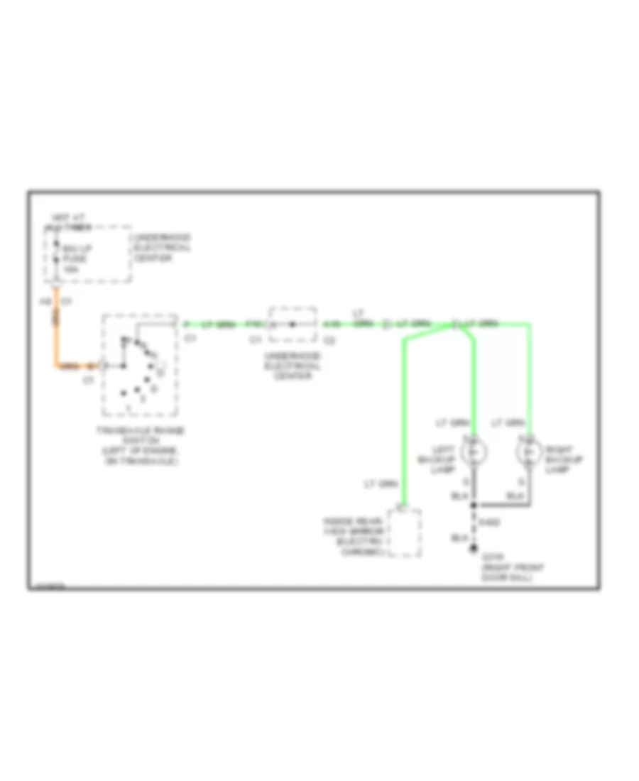
Back-up Lamps Wiring Diagram for Pontiac Grand Prix GTP 1998
List of elements for Back-up Lamps Wiring Diagram for Pontiac Grand Prix GTP 1998:
- A10
- A8 c1
- B/u lp fuse 10a
- F10
- G316 (right front door sill)
- Hot at all times
- Inside rear- view mirror (electro- chromic)
- Left backup lamp
- Right backup lamp
- S402
- Transaxle range switch (left of engine, on transaxle)
- Underhood electrical center
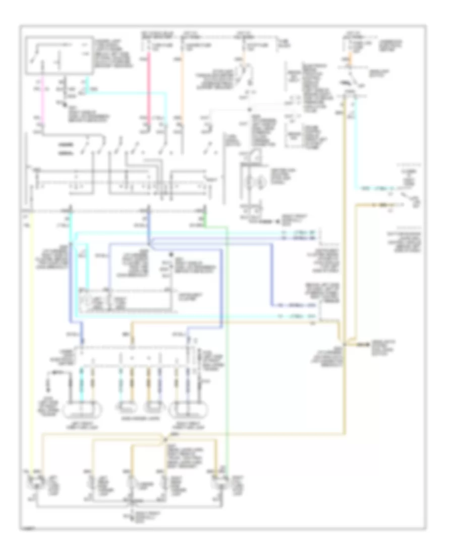
Exterior Lamps Wiring Diagram for Pontiac Grand Prix GTP 1998
List of elements for Exterior Lamps Wiring Diagram for Pontiac Grand Prix GTP 1998:
- (right front door sill) g316
- A c1
- A10
- A11
- B c1
- B11
- Behind left side of dash, left of steering wheel) body control module
- Brake sig.
- Brake sw input
- C11
- C12
- C14
- Center high mounted stoplamp (chmsl)
- Closed in night mode
- Cruise control module (front left of strut tower)
- D11
- Daytime running lamps (drl) control module (behind left side of dash)
- Electronic brake traction control module (ebtcm) (left side of engine compt, part of brake pressure modulator value)
- F10
- F11
- Fuse block
- G108 (left side of front end upper tie bar)
- G201 (right side of dash, on crossbeam behind fuse block)
- Hazard
- Hazard fuse 15a
- Hazard lamp/ turn signal lamp flasher (below left side of dash, mounted on multi-purpose bracket near bcm)
- Head
- Headlamp switch
- Headlights system (fog lamps switch)
- Hot at all times
- Hot in run, bulb test or start
- Instrument cluster
- Instrument cluster heads- up-display (hud) module (top left side of dash)
- Left
- Left front park/turn lamp
- Left rear side marker lamp
- Left tail/ turn/ stop- lamp
- Left turn indic
- License lamp
- Nca
- Normal
- Off
- Park
- Park lps fuse 20a
- Pk lps sw
- Pnk
- Right
- Right front park/turn lamp
- Right rear side marker lamp
- Right tail/ turn/ stop- lamp
- Right turn indic
- S124
- S204 (i/p harness, 4cm from data link connector breakout)
- S205 (i/p harness, left side of dash, near steering column harness connector)
- S230
- S289 (i/p harness, right side of cluster, 7cm from trip computer conn breakout)
- S290 (i/p harness, right side of cluster, behind trip computer conn breakout)
- S406
- S407 (rear lamps harn, right rear of trunk, 12cm from rear lamps harn body grommet)
- Side marker lamps
- Stop fuse 15a
- Stoplamp/ torque converter clutch switch (on brake pedal support bracket)
- Turn fuse 10a
- Turn signal switch
- Under- hood electrical center
- Underhood electrical center
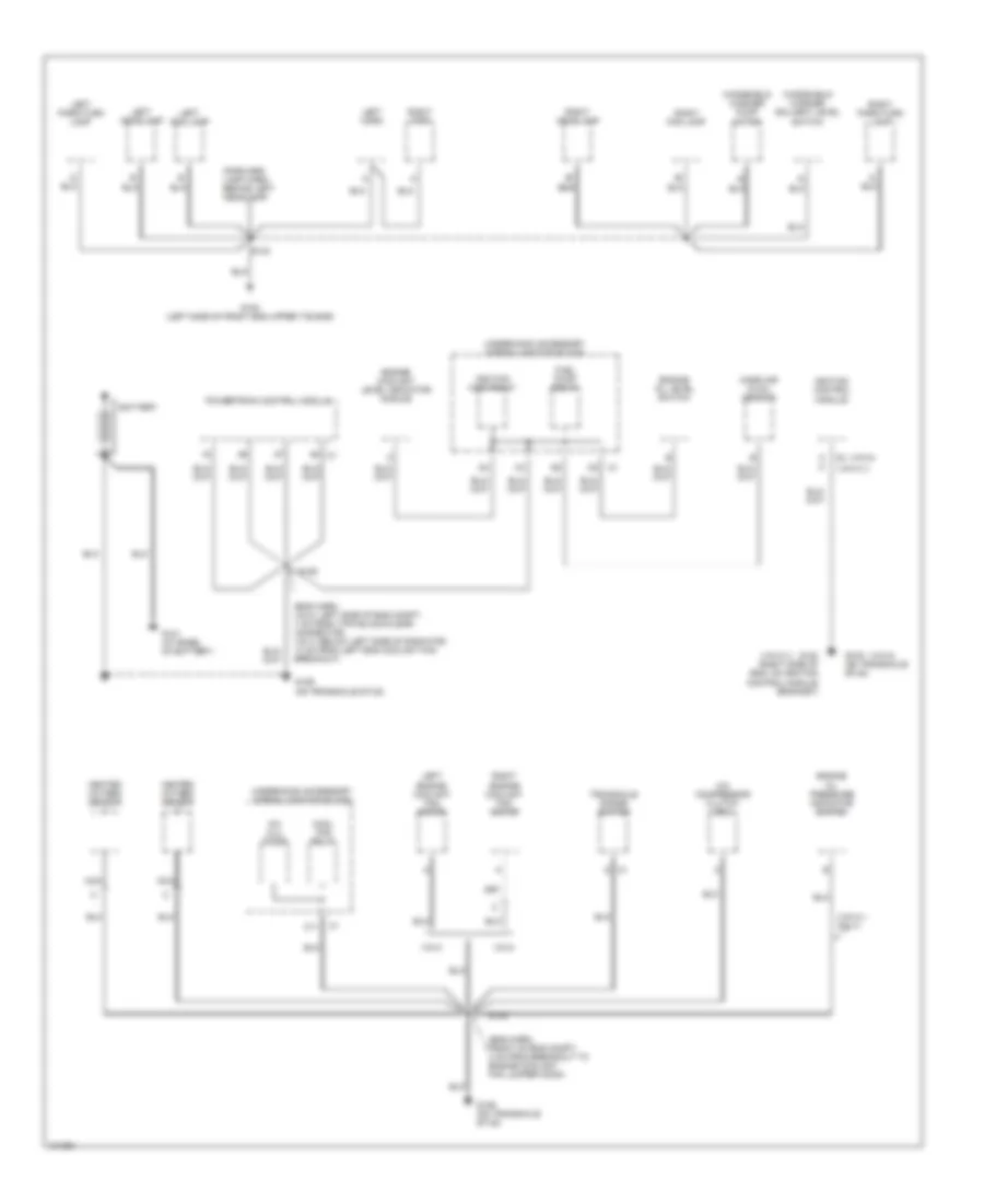
GROUND DISTRIBUTION
Ground Distribution Wiring Diagram (1 of 3) for Pontiac Grand Prix GTP 1998
List of elements for Ground Distribution Wiring Diagram (1 of 3) for Pontiac Grand Prix GTP 1998:
- (eng harn, front of eng compt, 4 cm from breakout to engine coolant fan jumper conn)
- (eng harn, vin m: left side of eng compt, 7 cm from 7-pin black/clear connector; vin x: below left side of radiator, 13 cm from left eng coolant fan breakout)
- (forward lamp harn, behind left headlamp)
- (vin k,1 only)
- (vin k,1)
- (vin m)
- A a
- A/c clu diode
- A/c compressor clutch coil
- B b
- Battery
- C1 d
- C11
- Cool fan relay
- Engine coolant level indicator module
- Engine oil level switch
- Engine oil pressure indicator switch
- Fuel pump relay
- G101 (at base of battery)
- G108 (left side of front end upper tie bar)
- G120 (right side of eng, on ignition control module bracket)
- G129 (on transaxle stud)
- Heated oxygen sensor
- Ignition control module
- Ignition main relay
- Left engine coolant fan motor
- Left fog lamp
- Left headlamp
- Left horn
- Left park/turn lamp
- Mass air flow sensor
- Nca
- Powertrain control module
- Right engine coolant fan motor
- Right fog lamp
- Right headlamp
- Right horn
- Right park/turn lamp
- S105
- S106
- S124
- Transaxle range switch
- Underhood accessory wiring junction block
- Vin k
- Vin m
- Windshield washer pump motor
- Windshield washer solvent level switch
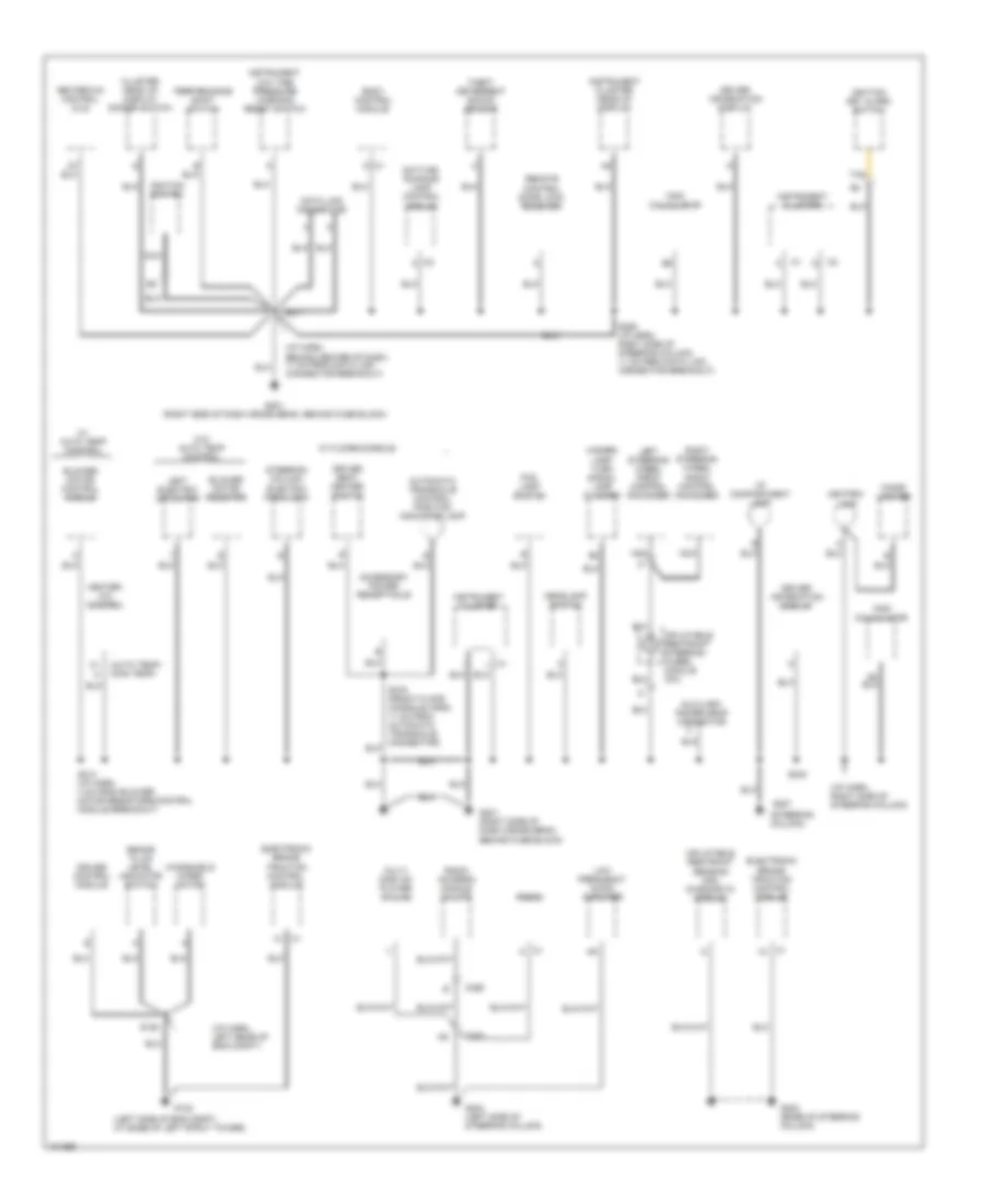
Ground Distribution Wiring Diagram (2 of 3) for Pontiac Grand Prix GTP 1998
List of elements for Ground Distribution Wiring Diagram (2 of 3) for Pontiac Grand Prix GTP 1998:
- (auto temp) (man temp)
- (i/p harn, behind center of dash, 11 cm from data link connector breakout)
- (i/p harn, left rear of eng compt)
- (i/p harn, right side of steering column)
- (left side of eng compt, at base of left strut tower)
- (steering column)
- Accessory power receptacle
- Ashtray lamp
- Automatic transaxle control position indicator lamp
- Auxiliary power drop connector
- Blower motor control module
- Blower motor resistor
- Body control module
- Brake fluid level indicator switch
- C1 d
- C1 k
- C1 l
- C2 a
- C200
- C395
- Cigar lighter
- Cluster head up display dimmer switch
- Cruise control module
- Data link connector
- Daytime running lamp control module
- Driver information display
- Driver seat heater switch
- Electronic brake traction control module
- Fog lamp switch
- G102
- G201 (right side of dash cross beam, behind fuse block)
- G202 (base of steering column)
- G204 (left side of steering column)
- G207
- Hazard lamp/ turn signal lamp flasher
- Headlamp switch
- Heater- a/c control
- Heater-a/c control (cj2)
- I/p compartment lamp
- Ignition key alarm switch
- Ignition switch
- Inflatable restraint sensing and diagnostic module
- Inflatable restraint steering wheel module coil
- Instrument
- Instrument cluster
- Instrument cluster head-up display
- Left electric actuator
- Left steering wheel radio control switches
- Low frequency audio amplifier
- Low tire pressure warning reset switch
- Multi disc cd player (w/ u18)
- Nca
- Performance shift switch
- Radio
- Radio antenna module (w/ u77)
- Remote control door lock receiver
- Right steering wheel radio control switches
- S125
- S211
- S213 (i/p harn, 4 cm from blower motor resistors/control module breakout)
- S230
- S285 (i/p harn, right side of steering column, 11 cm from data link connector breakout)
- Steering column electric park lock
- Tan
- Theft deterrent shock sensor
- Trip calculator
- W/ auto temp control
- W/ floor console
- W/o auto temp control
- Windshield wiper motor
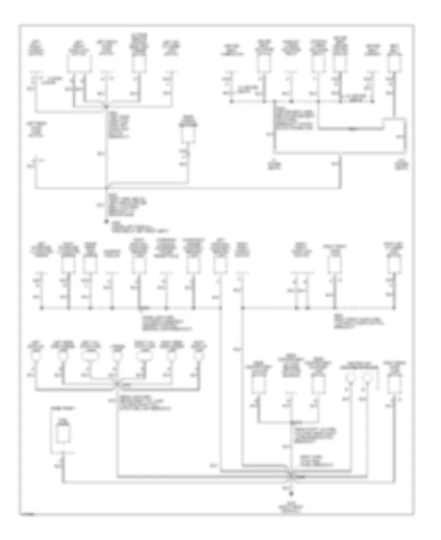
Ground Distribution Wiring Diagram (3 of 3) for Pontiac Grand Prix GTP 1998
List of elements for Ground Distribution Wiring Diagram (3 of 3) for Pontiac Grand Prix GTP 1998:
- (2 door)
- (4 door)
- (body harn, 15 cm from chmsl breakout)
- (dome lamp harn, 4 cm from windshield header courtesy/ reading lamps breakout)
- (rear compt lid harn, 8 cm from rear compt lid release switch breakout)
- (rear lamp harn, behind right tail lamp, 4 cm from right tail/ stop/turn lamp breakout)
- Center high mounted stoplamp
- Driver seat adjuster switch
- Driver seat heater control module
- Fore/aft lumbar adjuster relay
- Fuel pump
- Fuel tank
- G309 (inside left door sill, forward of left front seat)
- G316 (right front door sill)
- Heated seat element
- Heated seat thermistor
- Inside rear view mirror
- Left back-up lamp
- Left front door ajar switch
- Left front door lock switch
- Left front window switch
- Left key cylinder lock switch
- Left rear door ajar switch
- Left rear side marker lamp
- Left roof rail courtesy/ reading lamp
- Left sunshade illuminated mirror
- Left tail/ stop/turn lamp
- License lamp
- Nca
- Outside remote control rear view mirror switch
- Overhead console accessory power receptacle
- Rear compartment lid ajar switch
- Rear compartment courtesy lamp switch
- Rear compartment lid lock release actuator solenoid
- Rear window defogger
- Right back-up lamp
- Right front door lock
- Right front door lock switch
- Right front window switch
- Right key cylinder lock switch
- Right rear door ajar switch
- Right rear side marker lamp
- Right roof rail courtesy/ reading lamp
- Right sunshade illuminated mirror
- Right tail/ stop/turn lamp
- S303 (body harn, below left side of driver seat, 5 cm from breakout to ground g309)
- S330 (driver seat harn, below driver seat, 26 cm from breakout to 6-pin black connector)
- S390
- S402
- S406
- S416
- S504 (left door harn, 6 cm from left door lock switch breakout)
- S604 (right front door harn, 7 cm from window switch breakout)
- Seat belt switch
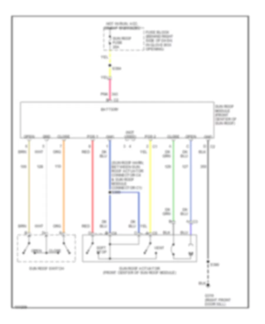
- Sunroof module
- Up/down lumbar adjuster relay
- W/ heated seats
- W/ power seats
- W/o power seats
- Windshield header courtesy/ reading lamp
HEADLIGHTS
Headlight Wiring Diagram for Pontiac Grand Prix GTP 1998
List of elements for Headlight Wiring Diagram for Pontiac Grand Prix GTP 1998:
- (i/p harn, behiind top of cluster, approx 9cm from cluster breakout)
- (i/p harn, behind left side of dash, approx 4cm from headlamp sw breakout)
- (i/p harn, right side of steering column, approx 17cm from data link conn breakout)
- (i/p harn, right side of steering column, approx 4cm from data link conn breakout)
- Body control module (left of steering column)
- Closed in day mode
- Closed in night mode
- Daytime running lamps ambient light sensor (top center of dash)
- Daytime running lamps control module (behind left side of dash)
- Daytime running lamps diode
- Dic/ hvac fuse 10a
- Drl fuse 10a
- E10
- E11
- E12
- E13
- Energized in night mode
- Exterior lights system
- Flash
- Fog lamp switch
- Fog lp fuse 10a
- Fog lps relay
- Fuse block (behind right side of dash)
- G108 (left side of front end upper tie bar)
- G201 (right side of dash, behind fuse block)
- Ground
- Head
- Headlamp circuit breaker 20a
- Headlamp dimmer switch
- Headlamp switch
- Hi-beam input
- High
- Hot at all times
- Hot in run
- Hot in run, bulb test and start
- Ignition input
- Illumination
- Instru- ment cluster
- Instrument cluster head-up display
- Instrument cluster system
- Interior lights system
- Left fog lamp
- Left head- lamp
- Light sensor input
- Low
- Low high
- Off
- On ind
- Park
- Park brake indicator switch
- Park brake input
- Park lamp off
- Park lp fuse 20a
- Pnk
- Regulator (5v)
- Right fog lamp
- Right head- lamp
- S124
- S204
- S206
- S219
- S221
- S230
- S261 (i/p harn, right side of steering column, approx 24cm from data link conn breakout)
- S265 (except base)
- S282
- S285
- Tan
- Theft deterrent relay (behind left side of dash)
- Underhood accessory wiring junction block (mounted to right strut tower)
HORN
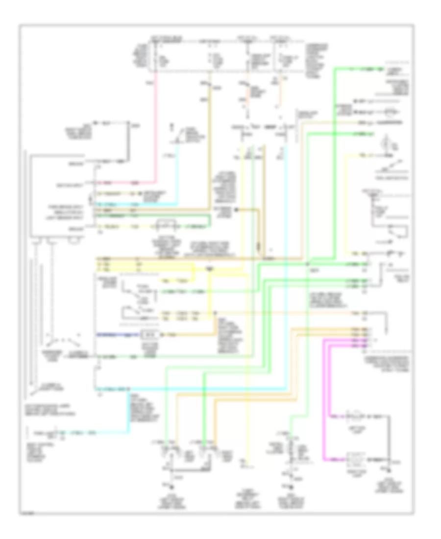
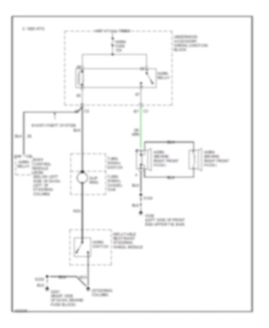
Horn Wiring Diagram for Pontiac Grand Prix GTP 1998
List of elements for Horn Wiring Diagram for Pontiac Grand Prix GTP 1998:
- (steering column)
- 1995 vftc c
- Body control module (bcm) (below left side of dash, left of steering column)
- D10
- G108 (left side of front end upper tie bar)
- G201 (right side of dash, behind fuse block)
- Horn (behind right front facia)
- Horn fuse 15a
- Horn relay
- Horn switch
- Hot at all times
- Inflatable restraint steering wheel module
- Nca
- S124
- S230
- Slip ring
- Turn signal cancel cam
- Turn signal switch
- Underhood accessory wiring junction block
- W/anti-theft system
INSTRUMENT CLUSTER
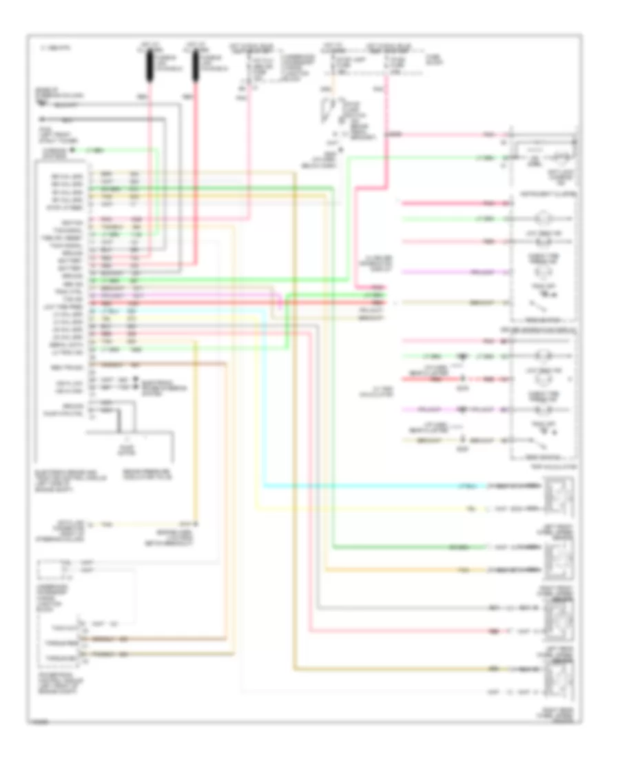
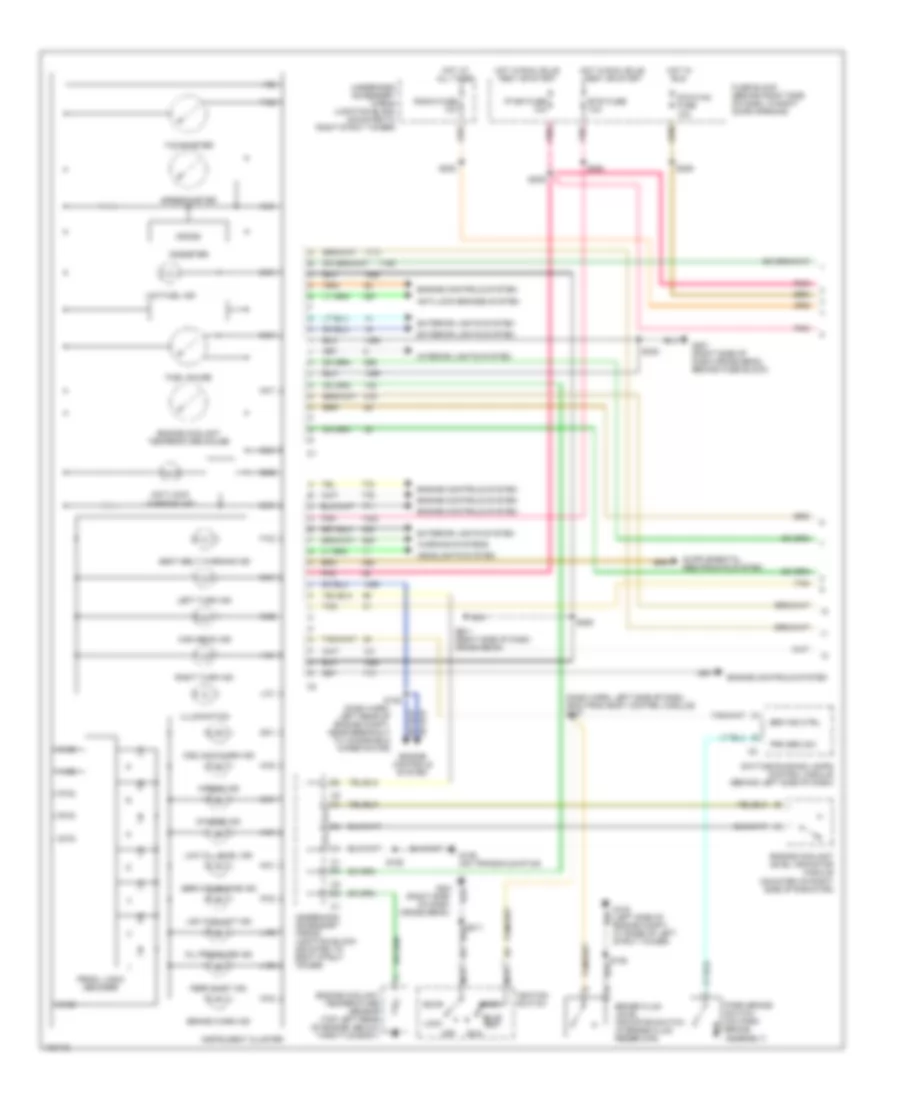
Instrument Cluster Wiring Diagram (1 of 2) for Pontiac Grand Prix GTP 1998
List of elements for Instrument Cluster Wiring Diagram (1 of 2) for Pontiac Grand Prix GTP 1998:
- (dash harn, left rear of engine compt, near breakout to windshield wiper motor)
- (dash harn, left side of dash, 36cm from body control module) s207
- (right side of dash cross beam)
- A-c1
- A-c2
- Accy
- Airbag ind
- Anti-lock brakes system
- Anti-lock warning ind
- B-c1
- B-c2
- Brake fluid level indicator switch (in brake fluid reservoir)
- Brake warn ind
- Brk ind ctrl
- Btsi fuse 10a
- Bulb test
- C-c1
- C-c2
- Charge ind
- Coolant warn ind
- D-c1
- D-c2
- Daytime running lamps control module (behind left side of dash)
- Dic/hvac fuse 10a
- E-c1
- E-c2
- Engine controls system
- Engine coolant level indicator module (mounted on right side of radiator)
- Engine coolant temperature gauge
- Engine coolant temperature sensor (top left rear of engine, below throttle body)
- Exterior lights system
- F-c2
- Fuel gauge
- Fuse block (behind right side of dash, in right door opening)
- G-c1
- G-c2
- G102 (left side of engine compt, at base of left strut tower)
- G129 (on transaxle stud)
- G201
- G201 (right side of dash cross beam)
- G201 (right side of dash cross beam, behind fuse block)
- H-c1
- H-c2
- Headlights system
- High beam ind
- Hot at all times
- Hot in run
- Hot in run, bulb test or start
- I-c2
- Ignition switch
- Illumination
- Instrument cluster
- Interior lights system
- Ip-ign fuse 10a
- J-c1
- J-c2
- K-c1
- K-c2
- L-c2
- Left turn ind
- Lock
- Low coolant ind
- Low fuel ind
- Low oil level ind
- M-c1
- N-c1
- Nca
- O-c1
- O-c2
- Odometer
- Off
- Oil pressure ind
- P-c2
- Park brake switch (on park brake assembly)
- Perf shift ind
- Pnk
- Prk brk sw
- Prndl logic decoder
- Q-c1
- Q-c2
- R-c2
- Radio fuse 10a
- Right turn ind
- Run
- S106
- S125
- S202
- S206
- S209
- S211
- S230
- S264
- S285
- Seat belt warning ind
- Service engine ind
- Speedometer
- Start
- Tachometer
- Tan
- Underhood accessory wiring junction block (mounted to right strut tower)
- Warning systems
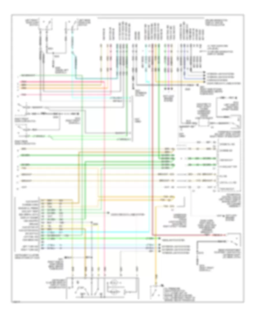
Instrument Cluster Wiring Diagram (2 of 2) for Pontiac Grand Prix GTP 1998
List of elements for Instrument Cluster Wiring Diagram (2 of 2) for Pontiac Grand Prix GTP 1998:
- (dash harn, right end of dash, 22cm from rke receiver harness breakout) s273
- (mounted to right strut tower) underhood accessory wiring junction block
- (not used)
- A10
- A11
- A12
- Anti-lock brakes system
- Aux chime out
- B10
- B11
- B12
- Batt (b+) in
- Change oil ind
- Charge ind
- Charge warn
- Chnge oil ind
- Computer data lines system
- Coolant temp
- D10
- D11
- D12
- Display dimmer
- Driver information display (did) or trip calculator
- Dwn
- E&c serial data
- E/m switch
- E/m switch in
- E11
- Engine oil press
- Exterior lights system
- G108 (left side of front end upper tie bar)
- G201 (right side of dash cross beam, behind fuse block)
- G201 (right side of dash cross-beam, behind fuse block)
- G207 (steering column)
- G309 (inside left door sill)
- G316 (right front door sill)
- Ground
- Headlights system
- Hi coolant tmp
- High beam ind
- Hud motor down
- Hud motor up
- Hud on/off
- Ign pwr in
- Instrument cluster head-up display (hud)
- Instrument cluster head-up display (hud) dimmer switch
- Interior lights system
- Left front door ajar switch
- Left rear door ajar switch
- Left turn ind
- Lft frt door ind
- Lft rr door ind
- Low fuel ind
- Low oil lvl ind
- Low trac ind
- Low wash fl ind
- Mil ind
- Not used
- Off
- Oil pressure indicator switch (3.1l: lower left of engine, above starter) 3.8l: lower right front of engine, above transaxle)
- Perf shift ind
- Pnk
- Powertrain control module (left front side of engine compt, in air cleaner assembly)
- Pwm dim in
- Rear compartment courtesy lamp switch (on rear compt lid, near latch)
- Right front door ajar switch
- Right rear door ajar switch
- Right turn ind
- Rt frt door ind
- Rt rr door ind
- S124
- S211
- S230
- S285
- S303
- S406
- S416
- S504
- S604
- Serial data i/o
- Spare ind
- Tach sig out
- Tan
- Tire press ind
- Trac off ind
- Trac sw out
- Trunk ajar ind
- Underhood accessory wiring junction block (mounted to right strut tower)
- Vf park in
- Vss 4000/ppm
- Vss sig in
- Vss sig out
- W/ driver information display (base)
- W/ trip computer (up-level)
- Warning systems
- Windshield washer solvent level switch (right front of eng compt)
INTERIOR LIGHTS
Courtesy Lamps Wiring Diagram for Pontiac Grand Prix GTP 1998
List of elements for Courtesy Lamps Wiring Diagram for Pontiac Grand Prix GTP 1998:
- (4 door only)
- (body harn, below rear s428
- (body harn, below right front seat)
- (body harn, under right front door sill)
- (dome lamp harn, near right "c" pillar)
- (i/p harn, 8 cm from blower motor resistors breakout)
- (inside left door sill, forward of left front seat)
- A nca
- B+ feed
- Body control module (behind left side of dash, left of steering column)
- Ctsy lps ctrl
- Dome
- Driver dr ajar
- G201 (right side of dash cross beam, behind fuse block)
- G309
- G316 (right front door sill)
- Headlamp switch
- Hot at all times
- I/p compartment lamp
- I/p compartment lamp switch
- Instrument cluster system
- Int lps on
- Left roof rail courtesy lamp
- Left front door ajar indicator switch
- Left front door courtesy warning lamp
- Left front roof rail courtesy/ reading lamp
- Left i/p courtesy lamp
- Left rear door ajar indicator switch
- Left sunshade lighted vanity mirror
- Nca
- Nca b
- Nca c
- Off
- Park lp fuse 20a
- Pass dr ajar
- Rear compartment courtesy lamp
- Rear compartment courtesy lamp diode
- Rear compartment courtesy lamp switch
- Red/
- Right front door ajar indicator switch
- Right front door courtesy warning lamp
- Right i/p courtesy lamp
- Right rear door ajar indicator switch
- Right sunshade lighted vanity mirror
- S230
- S259
- S303
- S309
- S311 (body harn, below right front seat)
- S317
- S390
- S393 (dome lamp harn, approx 4 cm from right courtesy lamp breakout)
- S398
- S416
- S504
- S604
- Tan
- Underhood accessory wiring junction block
- W/ rear reading lights
- W/o rear reading lights
- Window panel)
- Windshield header courtesy/ reading lamps
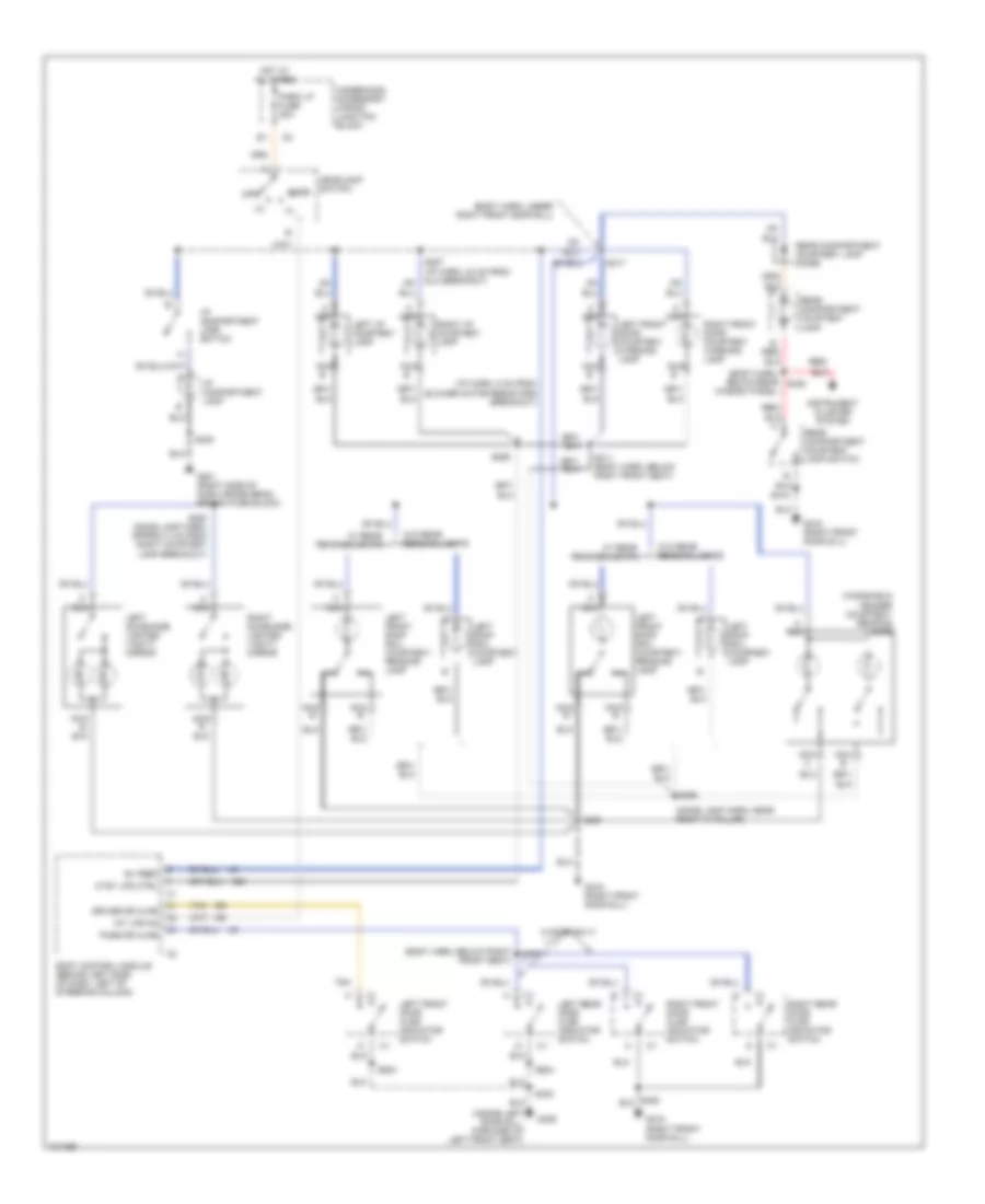
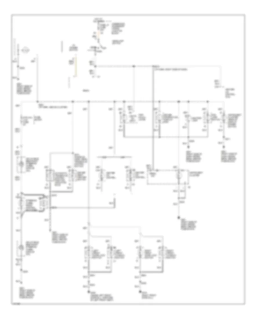
Instrument Illumination Wiring Diagram for Pontiac Grand Prix GTP 1998
List of elements for Instrument Illumination Wiring Diagram for Pontiac Grand Prix GTP 1998:
- (i/p harn, right side of dash)
- Ashtray lamp
- Automatic transaxle control position indicator bulb
- C16
- Cj2
- Driver information display (did)
- Driver seat heater switch
- Fog lamp switch
- Fuse block
- G201 (right side of dash cross beam, behind fuse block)
- G309 (inside left front door sill, forward of left front seat)
- G316 (right front door sill)
- Head
- Headlamp switch
- Heater- a/c control
- Heater- a/c control (cj2)
- Hot at all times
- I/p dimmer switch
- Inflatable restraint steering wheel module coil
- Instrument cluster
- Instrument cluster head-up display dimmer switch
- Left front door lock switch
- Left front window switch
- Lights on input
- Nca
- Off
- Park
- Park lp fuse 20a
- Prndl dim
- Radio
- Right front door lock switch
- Right front window switch
- S203 (i/p harn, above cluster)
- S211
- S212
- S213
- S230
- S303
- S374 (console harn, near transaxle control switch)
- S375
- S406
- S504
- S604
- Steering wheel radio control switches
- Str whl ilum fuse 2a
- Trip calcu- lator
- U40
- Underhood accessory wiring junction block
POWER DISTRIBUTION
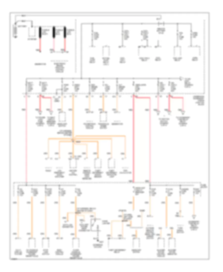
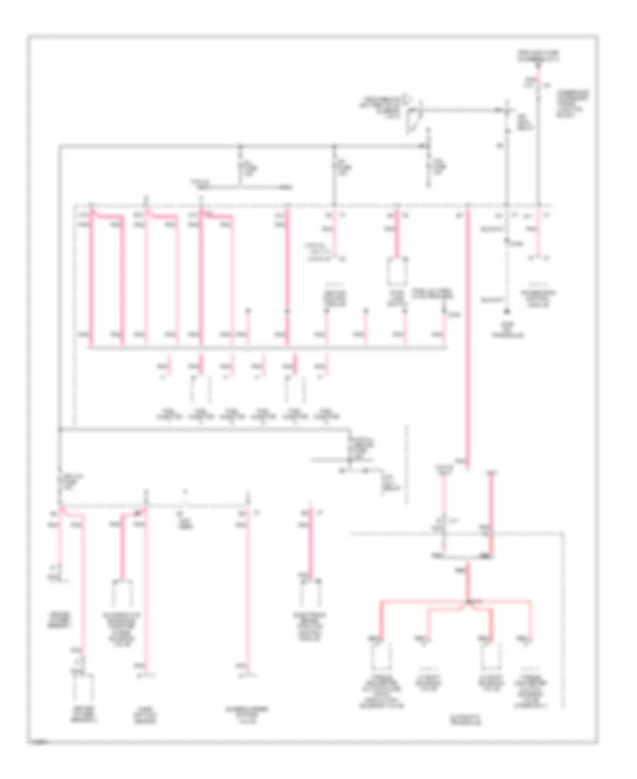
Power Distribution Wiring Diagram (1 of 4) for Pontiac Grand Prix GTP 1998
List of elements for Power Distribution Wiring Diagram (1 of 4) for Pontiac Grand Prix GTP 1998:
- (c60)
- (cj2)
- (i/p harn, left side of dash) s265
- (i/p harness, behind center of dash)
- (i/p harness, below center of dash) s238
- (not used)
- (steering column)
- A12
- Accessory time delay relay (diagram 2 of 4)
- Alt sense fuse 10a
- Aux/ cnsl fuse 15a
- Auxiliary power drop connector
- B/u lamp fuse 10a
- Base
- Batt main 1 maxi fuse 60a
- Batt main 2 maxi fuse 60a
- Battery
- Blower motor control module
- Blower motor resistor
- Body control module
- C60
- Cd chg fuse 10a
- Cig ltr fuse 15a
- Cigar lighter
- Cj2
- Cool fan 1 maxi fuse 30a
- Cool fan 1 relay
- Cool fan 2 maxi fuse 30a
- Cool fan 2 relay
- Cool relay
- Data link connector
- E c12
- E12
- Ecm sense fuse 10a
- Electronic brake traction control module
- Floor console accessory power receptacle
- Fog lamp relay
- Fog lp fuse 10a
- Fuel pump fuse 15a
- Fuel pump relay
- Fuse block
- Fusible link (rust)
- G207
- Generator
- Hazard fuse 15a
- Headlamp circuit breaker 20a
- Headlamp switch
- Headlamps maxi fuse 60a
- Heater- a/c control
- Horn fuse 15a
- Horn relay
- Hvac hi fuse 30a
- Ign main 1 maxi fuse 40a
- Ign main 2 maxi fuse 60a
- Int lamp fuse 10a
- Low frequency audio amplifier
- Multi disc cd player
- Oh console accessory power receptacle
- Outside remote control rear view mirror switch
- Park lp fuse 20a
- Powertrain control module
- Pwr mir fuse 10a
- Radio
- Radio batt fuse 10a
- Rap fuse 10a
- Red
- Remote battery stud
- Remote control door lock receiver
- S202
- Sc fuel pump relay (vin 1)
- Starter
- Stop lamp fuse 15a
- Stop lamp switch
- Theft deterrent indicator lamp
- Theft deterrent relay
- Theft deterrent shock sensor
- To accessory time delay relay (diagram 2 of 4)
- To ign main relay (diagram 3 of 4)
- To ignition switch (diagram 2 of 4)
- To power lock fuse (diagram 4 of 4)
- To seat circuit breaker (diagram 4 of 4)
- Transaxle range switch
- Trip calculator
- Turn signal switch
- Underhood accessory wiring junction block
- Uplevel
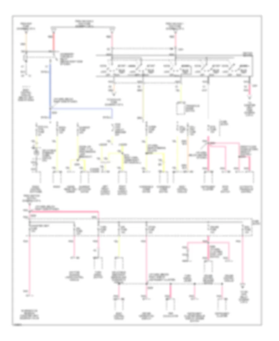
Power Distribution Wiring Diagram (2 of 4) for Pontiac Grand Prix GTP 1998
List of elements for Power Distribution Wiring Diagram (2 of 4) for Pontiac Grand Prix GTP 1998:
- (2 door) (4 door)
- (dome lmp harn, 11 cm from reading lamp breakout)
- (front floor console harn, near a/t control) s376
- (i/p harn, behind right side of instrument cluster)
- (i/p harn, below center of dash)
- (i/p harn, below right side of dash)
- (i/p harn, near steering column) s249
- 2 door
- 4 door
- Accessory time delay relay (behind right side of dash)
- Accy
- Automatic transaxle control
- Body control module
- Body control module (below left side of dash)
- Btsi fuse 10a
- Bulb test
- C13
- C201
- Canister vent fuse 10a
- Cruise control module
- Cruise control release switch
- Cruise fuse 10a
- Daytime running lamps control module
- Driver information display
- Drl fuse 10a
- Ecm fuse 10a
- Evaporative emission canister vent solenoid valve
- From ign main 1 maxi fuse (diagram 1 of 4)
- From ign main 2 maxi fuse (diagram 1 of 4)
- From ignition switch (diagram 2 of 4)
- From rap fuse (diagram 1 of 4)
- Fuse block
- H c
- I/p-ign fuse 10a
- Ignition switch
- Inflatable restraint sensing and diagnostic module
- Inflatable steering wheel module coil
- Inside rear view mirror
- Instrument cluster
- Instrument cluster head-up display dimmer switch
- Left front window switch
- Lock
- Mall fuse 10a
- Mall pgm fuse 10a
- Nca
- Off
- Pnk
- Pwr wdo circuit breaker 30a
- Radio
- Radio control switches
- Radio fuse 10a
- Red
- Right front window switch
- Run
- S209
- S220
- S228
- S264
- S266 (i/p harn, 21 cm from stop lamp switch)
- S310 (body harn, under right frt door sill)
- S394
- Sir fuse 15a
- Start
- Stop lamp switch
- Str whl ctrl fuse 2a
- Sunroof actuator motor
- Sunroof fuse 20a
- To canister vent fuse (diagram 2 of 4)
- To dic/hvac fuse (diagram 4 of 4)
- To ign main relay (diagram 3 of 4)
- Transaxle range switch
- Trip calculator
- Turn fuse 10a
- Turn signal lever
- Turn signal switch
- Windshield wiper motor
- Windshield wiper switch
- Wiper fuse 25a
Power Distribution Wiring Diagram (3 of 4) for Pontiac Grand Prix GTP 1998
List of elements for Power Distribution Wiring Diagram (3 of 4) for Pontiac Grand Prix GTP 1998:
- (fuel inj harn, 44 cm from pcm)
- (not used)
- (vin k &
- 1-2 shift solenoid valve
- 2-3 shift solenoid valve
- A/c clu relay
- A/c/clu abs/ign fuse 10a
- A12
- Automatic transaxle
- B (vin m)
- B12
- C11
- C12
- D11
- Dfi fuse 15a
- Electronic brake traction control module
- Evaporative emissions canister purge solenoid valve
- From ecm fuse (diagram 2 of 4)
- From remote l battery stud (diagram 1 of 4)
- Fuel injector
- G129 (on transaxle)
- Heated oxygen sensor 1
- Heated oxygen sensor 2
- Ign main relay
- Ign1-uh fuse 15a
- Ignition control module
- Inj fuse 10a
- Mass air flow sensor
- Nca
- P vin 1)
- Pnk
- Pnk c10
- Powertrain control module
- Red
- Red a
- S106
- S109
- S115
- Stop lamp switch
- Supercharger bypass valve
- Tcc fuse 10a
- Torque converter clutch pulse width modulation solenoid valve
- Torque converter clutch solenoid valve (4t60e-only)
- Underhood accessory wiring junction block
- Vin 1
- Vin k & vin 1
- Vin k & vin m
- Vin m
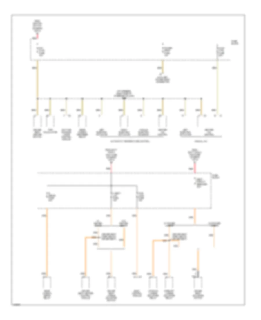
Power Distribution Wiring Diagram (4 of 4) for Pontiac Grand Prix GTP 1998
List of elements for Power Distribution Wiring Diagram (4 of 4) for Pontiac Grand Prix GTP 1998:
- (driver seat harn, below driver seat)
- (i/p harness, right side of steering column) s206
- Automatic temperature control
- Auxiliary power drop connector
- Body control module
- Daytime running lamps control module
- Dic/ hvac fuse 10a
- Driver seat adjuster switch
- Driver seat heater control module
- Driver seat heater switch
- Driver seat lumbar adjuster switch
- Fore/aft lumbar adjuster relay
- From batt main 2 maxi fuse (diagram 1 of 4)
- From ignition switch (diagram 2 0f 4)
- Fuse block
- H seat/ lum fuse 15a
- Heater- a/c control
- Hvac ctrl fuse 20a
- Left electric actuator
- Manual a/c
- Nca
- Power drop fuse 10a
- Pwr lock fuse 15a
- R defog fuse 30a
- Rear window defog relay
- Rear window defogger relay
- Red
- Right electric actuator
- S331
- S332
- Seat circuit breaker 20a
- Trip calculator
- Up/down lumbar adjuster relay
- Vacuum electric solenoid
- W/ heated seats
- W/ power lumbar
- W/o heated seats
- W/o power lumbar
POWER DOOR LOCKS
Power Door Lock Wiring Diagram for Pontiac Grand Prix GTP 1998
List of elements for Power Door Lock Wiring Diagram for Pontiac Grand Prix GTP 1998:
- left of steering column)
- (body harness, under right front seat) s314
- (right front door harness, 6cm from right door lock switch breakout) s604
- (right side of dash cross beam, behind fuse block)
- (w/ rke only)
- Accy 1
- B/u lamp fuse 10a
- Battery
- Battery (b+)
- Body control module (behind left side of dash,
- C13
- Door lk (batt)
- Door lock
- Door unlk cyl
- Door unlock
- Drvr dr unlk
- Fuse block (right side of dash)
- G201
- G309 (left door sill)
- G316 (right door sill)
- Ground
- Hot at all times
- Hot in accy or run
- Hot in run, bulb test or start
- I/p-ign fuse 10a
- Ignition 1
- Int lamp fuse 10a
- Interior lights system
- Left front door lock actuator
- Left front door lock switch
- Left key cylinder lock switch assembly (left front door)
- Left rear door lock actuator
- Lock
- Mall fuse 10a
- Nca
- Park input
- Park/neutral/position switch (on transaxle)
- Pass dr unlk
- Pnk
- Pwr lock fuse 15a
- Radio fuse 10a
- Remote control door lock receiver (rke) (left side of dash, behind driver information center)
- Rfa link
- Right front door lock actuator
- Right front door lock switch
- Right key cylinder lock switch assembly (right front door)
- Right rear door lock actuator
- Rr lid release
- S202
- S209
- S285
- S303 (body harness, under left front seat)
- S315 (body harness, under right front seat)
- S504 (left front door harness, 6cm from left door lock switch breakout)
- Tan
- Trunk, tailgate, fuel doors system
- Underhood accessory wiring junction block (mounted to right strut tower)
- Unlock
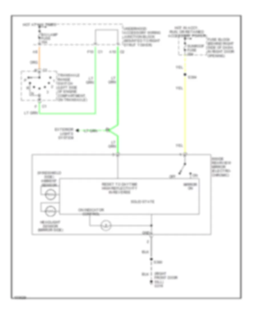
POWER MIRRORS
Photochromic Mirror Wiring Diagram for Pontiac Grand Prix GTP 1998
List of elements for Photochromic Mirror Wiring Diagram for Pontiac Grand Prix GTP 1998:
- (right front door sill) g316
- (windshield side) ambient sensor
- A10 c2
- B/u lamp fuse 10a
- Exterior lights system
- F10 c1
- Fuse block (behind right side of dash, in right door opening)
- Gnd
- Headlight sensor (mirror side)
- Hot at all times
- Hot in accy, run, or retained accessory power
- Inside rearview mirror (electro- chromic)
- Mirror on
- Off
- On indicator control
- Reset to daytime high reflectivity in reverse
- S390
- S394
- Solid state
- Sunroof fuse 20a
- Transaxle range switch (left side of engine compartment, on transaxle)
- Underhood accessory wiring junction block (mounted to right strut tower)
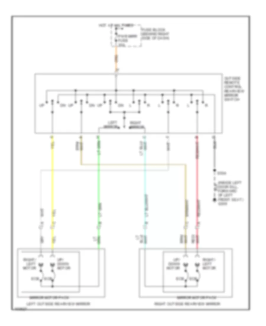
Power Mirrors Wiring Diagram for Pontiac Grand Prix GTP 1998
List of elements for Power Mirrors Wiring Diagram for Pontiac Grand Prix GTP 1998:
- (inside left door sill, forward of left front seat) g309
- Ecb
- Fuse block (behind right side of dash)
- Hot at all times
- Left mirror
- Left outside rearview mirror
- Mirror motor pack
- Outside remote control rearview mirror switch
- Pwr mirr fuse 10a
- Right mirror
- Right outside rearview mirror
- Right/ left motor
- S504
- Up/ down motor
POWER SEATS
6-Way Power Seat Wiring Diagram for Pontiac Grand Prix GTP 1998
List of elements for 6-Way Power Seat Wiring Diagram for Pontiac Grand Prix GTP 1998:
- Back
- Down
- Driver seat adjuster motor assembly
- Driver seat adjuster switch
- Entire seat
- For- ward
- Forward/ back adjuster motor w/ ecb
- Front height
- Front height adjuster motor w/ ecb
- Fuse block
- G309 (inside left door sill, forward of left front seat)
- Hot at all times
- Nca
- Rear height
- Rear height adjuster motor w/ ecb
- S330
- S331
- Seat circuit breaker 20a
- Tan
Driver's Heated Seat Wiring Diagram for Pontiac Grand Prix GTP 1998
List of elements for Driver's Heated Seat Wiring Diagram for Pontiac Grand Prix GTP 1998:
- Dic/hvac fuse 10a
- Driver seat back cushion cover
- Driver seat cushion cover
- Driver seat heater control module (below right side of driver seat)
- Driver seat heater switch
- Fuse block
- G201 (right side of dash cross beam, behind fuse block)
- G309 (inside left door sill, forward of left front seat)
- Ground
- Heated seat element
- Heating element
- Hot at all times
- Hot in run
- Hseat/lum fuse 15a
- Illum
- Interior lights system
- Lo/hi in
- Lumbar circuit
- Nca
- On in
- Pnk
- Pnk b
- S206
- S303
- S330
- S332
- S375
- Sensor
- Thermistor
Lumbar Wiring Diagram for Pontiac Grand Prix GTP 1998
List of elements for Lumbar Wiring Diagram for Pontiac Grand Prix GTP 1998:
- Aft
- Down
- Driver seat lumbar adjuster switch
- Fore
- Fore/aft lumbar adjuster relay (below driver seat)
- Fore/aft lumbar support motor
- Fuse block
- G309 (inside left door sill, forward of left front seat)
- H seat lum fuse 15a
- Heated seat circuit
- Hot at all times
- Pnk
- Power seat circuit
- Red
- S330
- S331
- Seat circuit breaker 20a
- Tan
- Up/down lumbar adjuster relay (below driver seat)
- Up/down lumbar support motor
POWER TOP/SUNROOF
Power Top/Sunroof Wiring Diagrams for Pontiac Grand Prix GTP 1998
List of elements for Power Top/Sunroof Wiring Diagrams for Pontiac Grand Prix GTP 1998:
- (not used)
- (sun roof harn, between sun roof actuator connector c4 & sun roof module connector c1) s399
- Battery
- Close
- Fuse block (behind right side of dash, in glove box opening)
- G316 (right front door sill)
- Gnd
- Hot in run, acc, or rap energized
- Open
- Pnk
- Pos 1
- Pos 2
- Red
- S390
- S394
- Soft stop
- Sun roof actuator (front center of sun roof module)
- Sun roof fuse 20a
- Sun roof module (front center of sun roof)
- Sun roof switch
- Vent
POWER WINDOWS
Power Window Wiring Diagram, 2 Door for Pontiac Grand Prix GTP 1998
List of elements for Power Window Wiring Diagram, 2 Door for Pontiac Grand Prix GTP 1998:
- (left front door sill, forward of left front seat)
- (pontiac) (chevrolet)
- Down
- Ecb
- Express
- Express down module
- Fuse block (behind right side of dash, in right door opening)
- G309
- Hot in run
- Illumination lamp
- Interior lights system
- Left front
- Left front window motor
- Left front window switch
- Power window circuit breaker 20a
- Right front
- Right front window motor
- Right front window switch
- S303
- S310 s318
- S504
- S604
- Tan
Power Window Wiring Diagram, 4 Door for Pontiac Grand Prix GTP 1998
List of elements for Power Window Wiring Diagram, 4 Door for Pontiac Grand Prix GTP 1998:
- (buick)
- (buick, olds)
- (buick: body harn, on floor under driver's seat)
- (chev, pontiac)
- (chev: crossbody harn below right front seat)
- (olds: body harn, center of floor behind front seats)
- (oldsmobile)
- (pontiac: body harn, on floor near center of vehicle)
- Buick oldsmobile
- Buick, olds chevrolet
- Chevrolet
- Down
- Ecb
- Express
- Express down module
- Fuse block (behind right side of dash, in right) door opening)
- G309 (left front door sill)
- G316 (right front door sill)
- Hot in acc, run or during rap
- Hot in run
- Illumination lamp
- Interior lights system
- Left front
- Left front window motor
- Left front window switch
- Left rear
- Left rear window motor
- Left rear window switch
- Lock out switch
- Pontiac
- Power window circuit breaker 20a
- Pwr window pwr sunroof circuit breaker 30a
- Right front
- Right front window motor
- Right front window switch
- Right rear
- Right rear window motor
- Right rear window switch
- S303
- S307
- S310 s410
- S504
- S604
- Tan
RADIO
Radio Wiring Diagrams, with Amplifier for Pontiac Grand Prix GTP 1998
List of elements for Radio Wiring Diagrams, with Amplifier for Pontiac Grand Prix GTP 1998:
- (behind dash, left side of steering column)
- (behind dash, right side of steering column) data link connector
- A10
- A11
- A12
- Amp on input
- Antenna
- Antenna module
- Audio common
- B red
- B10
- B11
- B12
- Bare
- Battery power
- Cd chg fuse 10a
- Cd lt signal
- Cd rt signal
- Common
- Drain
- E & c dataline
- E&c data
- F7 c2
- Fixed mast antenna
- Fuse block
- G202
- Ground
- Hot at all times
- Hot in acc, run or w/ retained accessory power
- Ign power
- Ignition power
- Inflatable restraint steering wheel control coil
- Interior lights
- Interior lights system
- Left front door speaker
- Left front tweeter
- Left rear speaker
- Left rear subwoofer speaker
- Left sig
- Left steering wheel radio controls
- Lights on input
- Low frequency audio amplifier
- Lr sub
- Lt frt
- Lt frt spkr
- Lt rear
- Lt rear spkr
- Multi-disc cd player (if equipped)
- Nca
- Pnk
- Power
- Radio
- Radio antenna module
- Radio fuse 15a
- Radio on
- Radio on out
- Rear window antenna grid
- Right front door speaker
- Right front tweeter
- Right rear speaker
- Right rear subwoofer speaker
- Right sig
- Right steering wheel radio controls
- Rr sub
- Rt frt
- Rt frt spkr
- Rt rear
- Rt rear spkr
- S202
- S225
- Str whl fuse 2a
- Strg whl ctrls
- Sw 1
- Sw 2
- Sw 3
- Sw 4
- Sw 5
- Sw 6
- Sw 7
- Sw 8
- Tan
- Underhood accessory wiring junction block
- Vf dim input
Radio Wiring Diagrams, without Amplifier for Pontiac Grand Prix GTP 1998
List of elements for Radio Wiring Diagrams, without Amplifier for Pontiac Grand Prix GTP 1998:
- (behind dash, right side of steering column) data link connector
- Antenna
- Antenna module
- Audio common
- B red
- Bare
- Battery power
- Cd chg fuse 10a
- Cd lt signal
- Cd rt signal
- Common
- Drain
- E & c dataline
- E&c data
- F7 c2
- Fixed mast antenna
- Fuse block
- G202 (behind dash, left side of steering column)
- Ground
- Hot at all times
- Hot in acc, run or w/ retained accessory power
- Ignition power
- Inflatable restraint steering wheel control coil
- Interior lights
- Interior lights system
- Left front rear speaker
- Left rear speaker
- Left sig
- Left steering wheel radio controls
- Lights on input
- Lt frt spkr
- Lt rear spkr
- Multi-disc cd player (if equipped)
- Nca
- Power
- Radio
- Radio antenna module
- Radio fuse 15a
- Radio on out
- Rear window antenna grid
- Right front rear speaker
- Right rear speaker
- Right sig
- Right steering wheel radio controls
- Rt frt spkr
- Rt rear spkr
- S202
- S225
- Str whl fuse 2a
- Strg whl ctrls
- Sw 1
- Sw 2
- Sw 3
- Sw 4
- Sw 5
- Sw 6
- Sw 7
- Sw 8
- Tan
- Underhood accessory wiring junction block
- Vf dim input
SHIFT INTERLOCKS
Shift Interlock Wiring Diagram for Pontiac Grand Prix GTP 1998
List of elements for Shift Interlock Wiring Diagram for Pontiac Grand Prix GTP 1998:
- A16
- Automatic tranmission shift lock control actuator (btsi) (on underside of steering column)
- Automatic transaxle control (btsi) (center of console assembly)
- Btsi fuse 10a
- Btsi solenoid
- C201
- Fuse block
- G129 (transaxle stud)
- G201 (right side of dash cross beam, behind fuse block)
- Hot in off, run, bulb test & start
- Park lock solenoid
- Park position switch
- Pnk
- Pnk a
- S105
- S213
- S264
- S376
- Steering column electric park lock (in steering column, near ignition key cylinder)
- Stoplamp switch (right side of brake pedal bracket)
- Transaxle range switch (left side of engine compt)
- Underhood accessory wiring junction block (mounted to right strut tower)
- W/ cloumn shift
- W/ floor shift
- W/console only
STARTING/CHARGING
Charging Wiring Diagram for Pontiac Grand Prix GTP 1998
List of elements for Charging Wiring Diagram for Pontiac Grand Prix GTP 1998:
- (1997)
- (1998)
- (not used) a
- (not used) c
- Alt sense fuse 10a
- B +
- B35
- Battery
- Charge warning indicator
- Charge warning indicator control
- E12 c1
- F p
- F5 c1
- Fuse block (behind right side of dash, in right door opening)
- Fusible link (10 ga- rust)
- G101 (at base of battery)
- G129 (on transaxle stud)
- Gen input
- Generator
- Generator term. l output
- Hot at all times
- Hot in run, bulb test or start
- I/p ign fuse 10a
- Instrument cluster
- Instrument cluster head-up display
- Pnk
- Power distribution system
- Powertrain control module (pcm) (in air cleaner assembly)
- Red
- S209
- Starter solenoid
- Underhood accessory wiring junction block
Starting Wiring Diagram for Pontiac Grand Prix GTP 1998
List of elements for Starting Wiring Diagram for Pontiac Grand Prix GTP 1998:
- Accy
- B red
- Battery
- Bulb test
- Charging circuit
- Fusible link (10 ga- rust)
- G101 (at base of battery)
- G129 (on transaxle stud)
- Hold- in coil
- Ign main 1 maxifuse 40a
- Ignition switch
- Lock
- Off
- Power distribution system
- Pull- in coil
- Red
- Remote battery stud
- Run
- Start
- Starter motor
- Starter solenoid
- Transaxle range switch (on transaxle)
- Underhood accessory wiring juncton block
SUPPLEMENTAL RESTRAINTS
Supplemental Restraint Wiring Diagram for Pontiac Grand Prix GTP 1998
List of elements for Supplemental Restraint Wiring Diagram for Pontiac Grand Prix GTP 1998:
- (center of wheel) inflatable restraint steering wheel module
- Air bag indicator
- B nca
- Bar
- Body control module (behind left side of dash)
- Computer data lines
- Data link connector (right of steering column)
- Driv side high
- Driv side low
- Fuse block (behind right side of dash)
- G202 (at base of steering column)
- G309 (inside left door sill)
- Ground
- Hot in run, bulb test, or start
- I/p-ign fuse 10a
- Ign pos volt
- Indicator lamp
- Inflatable restraint i/p module (upper right side of dash)
- Inflatable restraint sensing and diagnostic module (under right front seat)
- Inflatable steering wheel module coil
- Instrument cluster
- Nca
- Pass side high
- Pass side low
- Pnk
- S209 (dash harn, behind left side of cluster)
- S226 (dash harn, below right side of dash)
- S237 (dash harn, behind center of dash)
- S303 (body harn, below left side of driver's seat)
- Seat belt sw
- Seat belt switch
- Serial data
- Shorting
- Shorting bar
- Sir fuse 15a
- Tan
TRANSMISSION
3.1L
3.1L (VIN M), Transmission Wiring Diagram, 4T60-E for Pontiac Grand Prix GTP 1998
List of elements for 3.1L (VIN M), Transmission Wiring Diagram, 4T60-E for Pontiac Grand Prix GTP 1998:
- (eng harn, left side of eng compt approx 4 cm from ebtcm module breakout) s131
- (eng harn, top front of engine approx 4 cm from generator breakout)
- (fuel inj harn, approx 2 cm from fuel inj no 3 breakout)
- 1-2 shift sol
- 2-3 shift sol
- 5v reference a
- A12
- Automatic transaxle (4t60-e)
- Automatic transaxle fluid temperature sensor
- B10
- Battery in
- Body control module, driver information display, electronic brake control lamp driver module & head-up display dimmer switch
- C10
- Class ii data
- D10
- D11
- Data link connector (partial) (below dash, right of steering column)
- Ecm fuse 10a
- Ecm sense fuse 10a
- Ect sensor in
- Engine controls system
- Engine coolant temperature sensor (below throttle body)
- F12 underhood accessory wiring j/b
- Fuse block (right side of dash)
- G129 (left side of engine on transaxle stud)
- G129 (lower left side of engine on transaxle stud)
- Hot at all times
- Hot in run, bulb test or start
- I/p ign fuse 10a
- Ign main relay
- Ignition in
- Instrument cluster
- Malfunction indicator lamp
- Mil ctrl
- Pcm ground
- Pnk
- Powertrain control module (in engine air cleaner assembly)
- Red
- S105
- S106
- S121
- S122
- S209
- Sensor return
- Stop lamp switch
- Tan
- Tcc fuse 10a
- Tcc pwm sol
- Tcc sol
- Tcc/ brake switch
- Tcc/brake sw in
- Tft sensor in
- Throttle position sensor
- Tp sensor in
- Tp sensor return
- Tr sw a
- Tr sw b
- Tr sw c
- Tr sw in-a
- Tr sw in-b
- Tr sw in-c
- Tr sw in-p
- Tr sw prty
- Transaxle range switch (left side of engine compt on transaxle)
- Uart data
- Underhood accessory wiring j/b (right front strut tower)
- Vehicle speed sensor (lower right rear of engine compt, end of transaxle)
- Vss hi in
- Vss lo in
3.8L
3.8L (VIN 1), Transmission Wiring Diagram, 4T65-E for Pontiac Grand Prix GTP 1998
List of elements for 3.8L (VIN 1), Transmission Wiring Diagram, 4T65-E for Pontiac Grand Prix GTP 1998:
- (eng harn, left side of eng compt approx 4 cm from ebtcm module breakout) s131
- (i/p harn, approx 7 cm from windshield wiper motor breakout) s125
- 1-2 shift sol
- 2-3 shift sol
- 5v reference a
- A/t iss sensor hi
- A/t iss sensor lo
- A12
- Automatic transaxle (4t65-e)
- Automatic transaxle fluid pressure manual valve position switch
- Automatic transaxle fluid temperature sensor
- Automatic transaxle input shaft speed sensor
- B10
- Battery in
- Body control module, driver information display, hud dimmer switch & trip calculator
- C10
- Class ii data
- D10
- D11
- Data link connector (partial) (below dash, right of steering column)
- Ecm fuse 10a
- Ecm sense fuse 10a
- Ect sensor in
- Ect sensor return
- Engine controls system
- Engine coolant temperature sensor (below throttle body)
- F12
- Fuse block (right side of dash)
- G129 (left side of engine on transaxle stud)
- G129 (lower left side of engine on transaxle stud)
- G201 (behind fuse block)
- Hot at all times
- Hot in run, bulb test or start
- I/p ign fuse 10a
- Ign main relay
- Ignition in
- Instrument cluster
- Malfunction indicator lamp
- Mil ctrl
- Nca
- Pc sol hi
- Pc sol lo
- Pcm ground
- Perf shift indicator
- Perform shift in
- Performance shift switch (3.8l vin 1- supercharged)
- Pnk
- Powertrain control module (in engine air cleaner assembly)
- Pressure control sol
- Red
- Rev
- S105
- S106
- S122 (eng harn, top left rear of engine)
- S209
- S211
- Stop lamp switch
- Tan
- Tcc fuse 10a
- Tcc pwm sol
- Tcc release
- Tcc release in
- Tcc/ brake switch
- Tcc/brake sw in
- Tft sensor in
- Tft sensor return
- Throttle position sensor
- Tp sensor in
- Tp sensor return
- Tr sw a
- Tr sw b
- Tr sw c
- Tr sw in-a
- Tr sw in-b
- Tr sw in-c
- Tr sw in-p
- Tr sw prty
- Trans range a in
- Trans range b in
- Trans range c in
- Transaxle range switch (left side of engine compt on transaxle)
- Uart data
- Underhood accessory wiring j/b
- Underhood accessory wiring j/b (right front strut tower)
- Vehicle speed sensor (lower right rear of engine compt, end of transaxle)
- Vss hi in
- Vss lo in
3.8L (VIN K), Transmission Wiring Diagram, 4T65-E for Pontiac Grand Prix GTP 1998
List of elements for 3.8L (VIN K), Transmission Wiring Diagram, 4T65-E for Pontiac Grand Prix GTP 1998:
- (eng harn, left side of eng compt approx 4 cm from ebtcm module breakout) s131
- (i/p harn, approx 7 cm from windshield wiper motor breakout) s125
- 1-2 shift sol
- 2-3 shift sol
- 5v reference a
- A/t iss sensor hi
- A/t iss sensor lo
- A12
- Automatic transaxle (4t65-e)
- Automatic transaxle fluid pressure manual valve position switch
- Automatic transaxle fluid temperature sensor
- Automatic transaxle input shaft speed sensor
- B10
- Battery in
- Body control module, driver information display, hud dimmer switch & trip calculator
- C10
- Class ii data
- D10
- D11
- Data link connector (partial) (below dash, right of steering column)
- Ecm fuse 10a
- Ecm sense fuse 10a
- Ect sensor in
- Ect sensor return
- Engine controls system
- Engine coolant temperature sensor (below throttle body)
- F12
- Fuse block (right side of dash)
- G129 (left side of engine on transaxle stud)
- G129 (lower left side of engine on transaxle stud)
- G201 (behind fuse block)
- Hot at all times
- Hot in run, bulb test or start
- I/p ign fuse 10a
- Ign main relay
- Ignition in
- Instrument cluster
- Malfunction indicator lamp
- Mil ctrl
- Nca
- Pc sol hi
- Pc sol lo
- Pcm ground
- Perf shift indicator
- Perform shift in
- Performance shift switch (3.8l vin 1- supercharged)
- Pnk
- Powertrain control module (in engine air cleaner assembly)
- Pressure control sol
- Red
- Rev
- S105
- S106
- S122 (eng harn, top left rear of engine)
- S209
- S211
- Stop lamp switch
- Tan
- Tcc fuse 10a
- Tcc pwm sol
- Tcc release
- Tcc release in
- Tcc/ brake switch
- Tcc/brake sw in
- Tft sensor in
- Tft sensor return
- Throttle position sensor
- Tp sensor in
- Tp sensor return
- Tr sw a
- Tr sw b
- Tr sw c
- Tr sw in-a
- Tr sw in-b
- Tr sw in-c
- Tr sw in-p
- Tr sw prty
- Trans range a in
- Trans range b in
- Trans range c in
- Transaxle range switch (left side of engine compt on transaxle)
- Uart data
- Underhood accessory wiring j/b
- Underhood accessory wiring j/b (right front strut tower)
- Vehicle speed sensor (lower right rear of engine compt, end of transaxle)
- Vss hi in
- Vss lo in
TRUNK, TAILGATE, FUEL DOOR
Trunk Release Wiring Diagram for Pontiac Grand Prix GTP 1998
List of elements for Trunk Release Wiring Diagram for Pontiac Grand Prix GTP 1998:
- B/u lp fuse 10a
- Body control module (bcm) (left of steering column)
- C1 c
- G316 (right front door sill)
- Hot at all times
- Park input
- Rear compart- ment lid lock release solenoid (mounted to rear compt lid, near latch)
- Rear compartment lid release relay (below left side of dash, mounted to bcm mounting bracket)
- Rear compartment lid release switch
- Remote control door lock reciever (rcdlr) (behind left side of dash, on right side of instrument cluster)
- S416
- Transaxle range switch (left of engine compt, on transaxle)
- Underhood accessory wiring junction block (mounted to right front strut tower)
WARNING SYSTEMS
Warning System Wiring Diagrams for Pontiac Grand Prix GTP 1998
List of elements for Warning System Wiring Diagrams for Pontiac Grand Prix GTP 1998:
- (i/p harn, approx 3 cm from remote control door lock receiver breakout) s262
- (i/p harn, approx 4 cm from from headlamp switch break- out)
- (i/p harn, approx 7 cm from driver's information display/trip calculator breakout) s289
- (i/p harn, approx at the driver's information display/trip calculator breakout) s290
- Accy1
- Aux chime
- Base
- Bat
- Body control module (bcm) (below left side of dash, left of steering column)
- C12
- C13
- C14
- C15
- C201
- D12
- Driver information display (did)
- Driver's door ajar input
- Driver's seat belt switch
- Exterior lights system
- Fasten belts output
- Fasten belts warning ind
- Fuse block
- G201 (right side of dash cross beam, behind fuse block)
- G309 (left front door sill)
- Ground
- Hazard lamp & turn signal lamp flasher (below left side of dash)
- Head
- Head- lights system
- Headlamp switch
- Hot at all times
- Hot in accy or run
- Hot in run, bulb test or start
- I/p-ign fuse 10a
- Ign
- Ign 1
- Ignition key alarm switch
- Instru- ment cluster
- Instrument cluster system
- Int lamp fuse 10a
- Key in ign input
- Left front door lock (ajar indicator switch)
- Left turn input
- Lights off input
- Mall fuse 10a
- Mall pgm fuse 10a
- Nca
- Off
- Park
- Park lp fuse 20a
- Pnk
- Powertrain control module (pcm) (left side of engine compt, in side air cleaner)
- Right turn input
- S209
- S226 (i/p harn, approx 11 cm from blower motor resistor/ control module breakout)
- S282
- S285
- S303
- S504
- Seat belt switch input
- Tan
- Trip calculator
- Turn signal switch
- Underhood (u/h) electrical center
- Underhood accessory wiring junction block
- Up level
- Vehicle speed input
WIPER/WASHER
Wiper/Washer Wiring Diagram for Pontiac Grand Prix GTP 1998
List of elements for Wiper/Washer Wiring Diagram for Pontiac Grand Prix GTP 1998:
- 1998-99
- A12
- F12
- Fuse block (behind right side of dash)
- G101 (right side of front end upper tie bar)
- G102 (at base of left strut tower)
- G108 (left side of front end upper tie bar)
- Hot in acc or run
- Mist
- Off
- Pulse
- Red
- S123
- S124
- S125
- S249
- Underhood accessory wiring junction block (on right strut tower)
- Underhood electrical center (right strut tower)
- Washer switch
- Windshield washer pump
- Windshield washer pump motor
- Windshield wiper motor
- Windshield wiper/washer switch
- Wiper fuse 25a
- Wiper motor controller
- Wiper switch

 Čeština
 Dansk
Dansk Deutsch
 English
 English
 Español
 Suomi
Suomi Français
 Français
 עברית
עברית Hrvatski
 Magyar
 Italiano
 日本語
日本語 한국어
한국어 Nederlands
 Polski
 Português
 Português
 Română
 Русский
 Slovenčina
 Slovenščina
 Svenska
 Türkçe
 中文 (中国)