AIR CONDITIONING
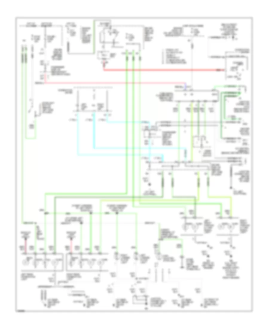
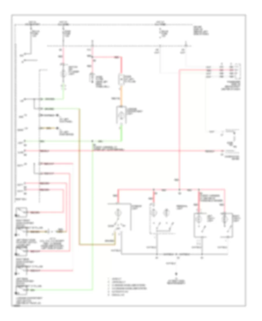
2.4L
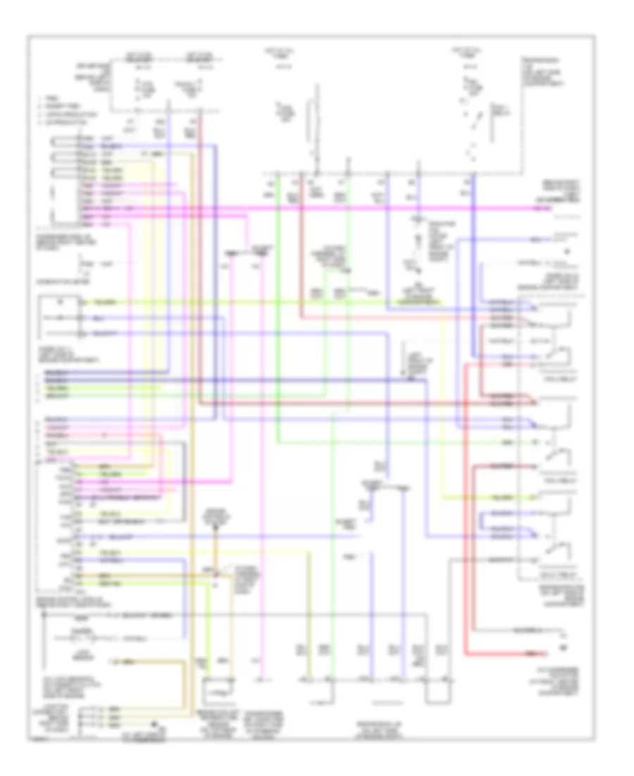
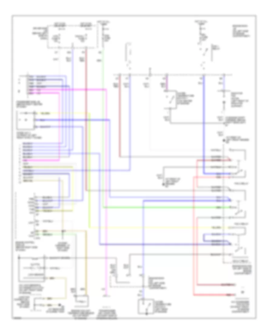
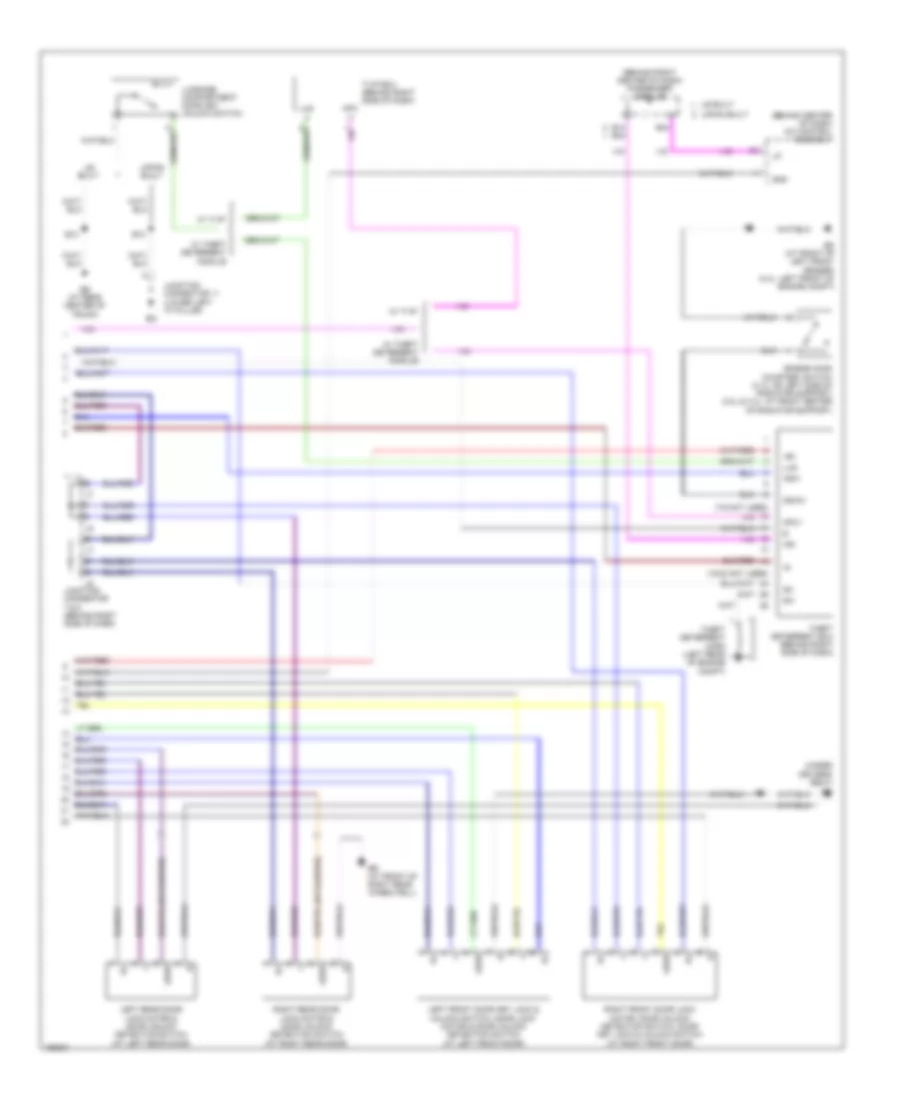
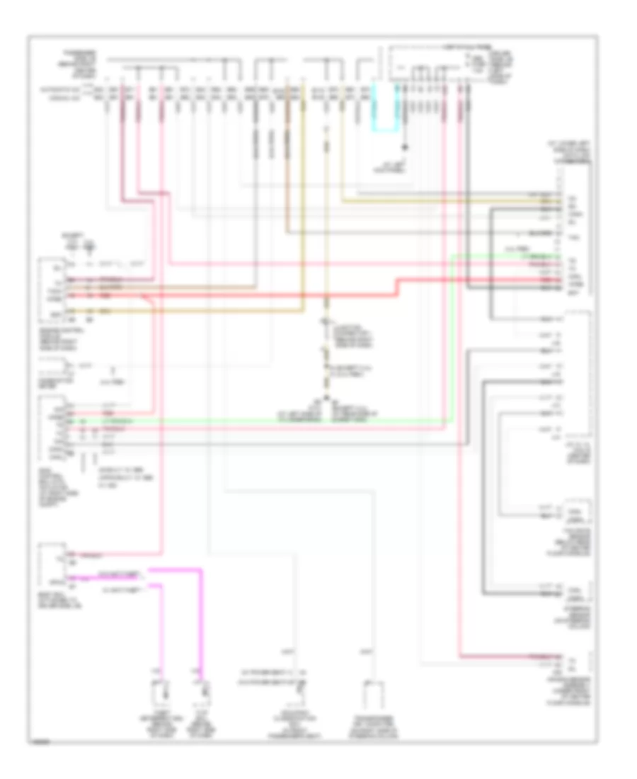
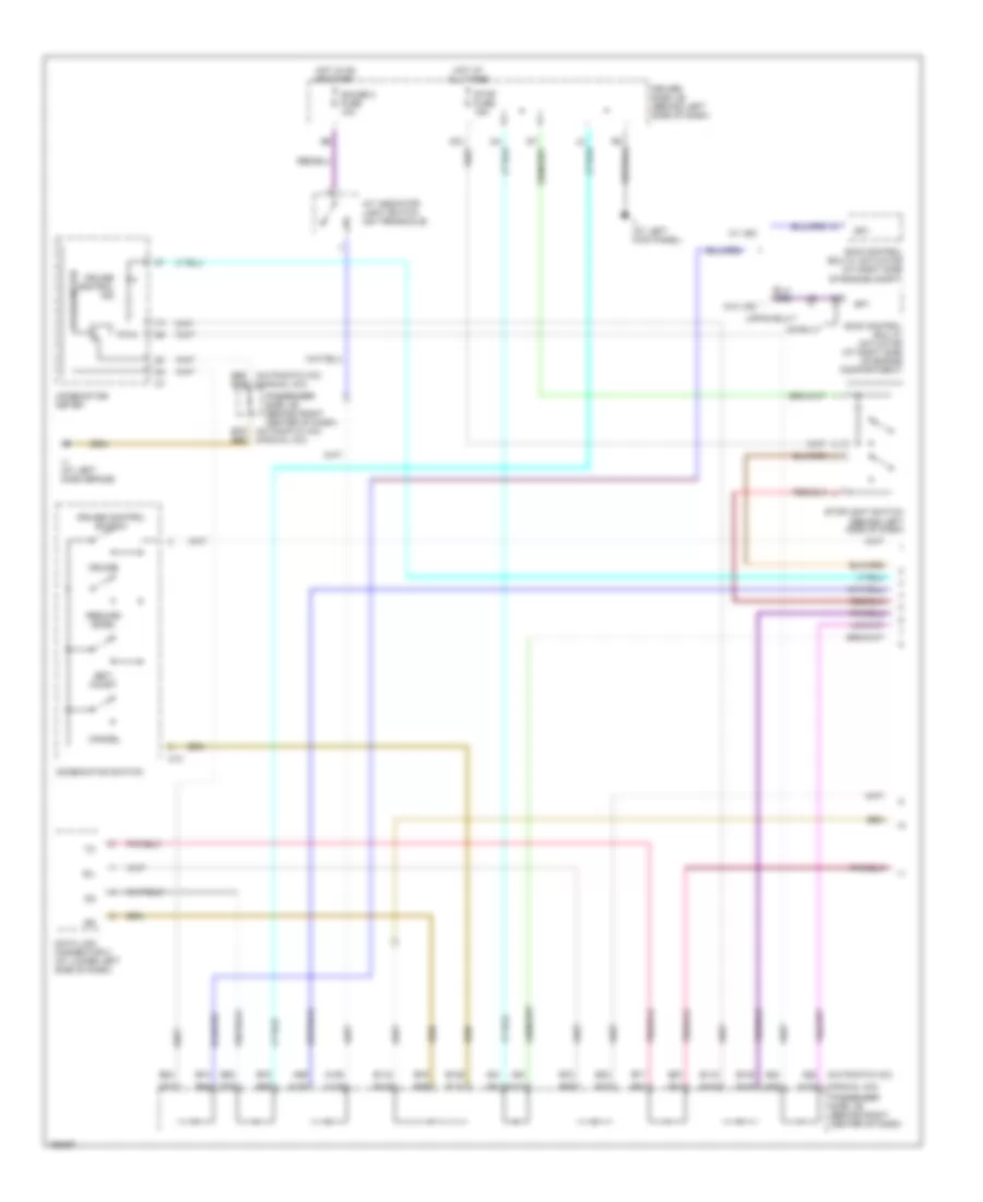
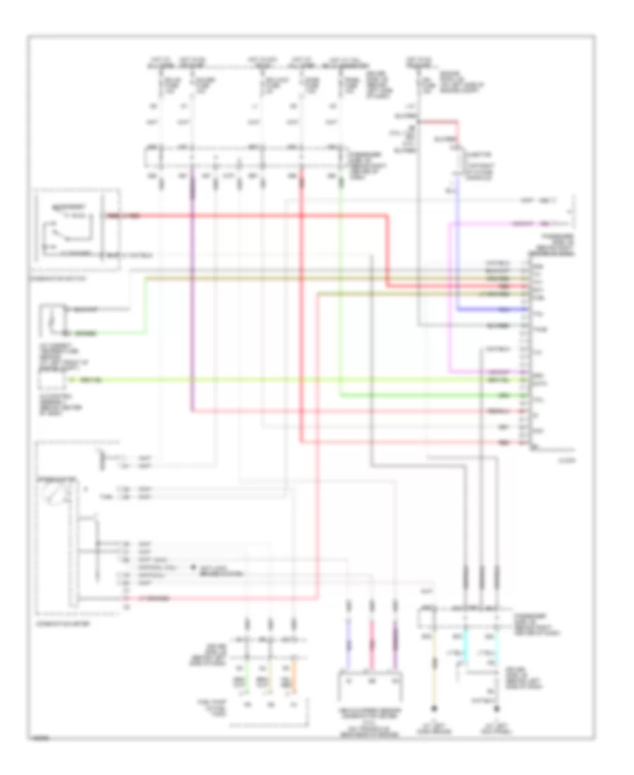
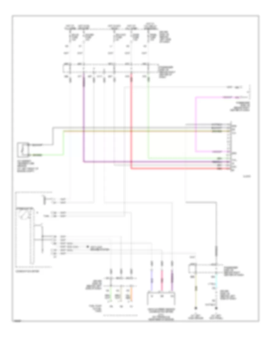
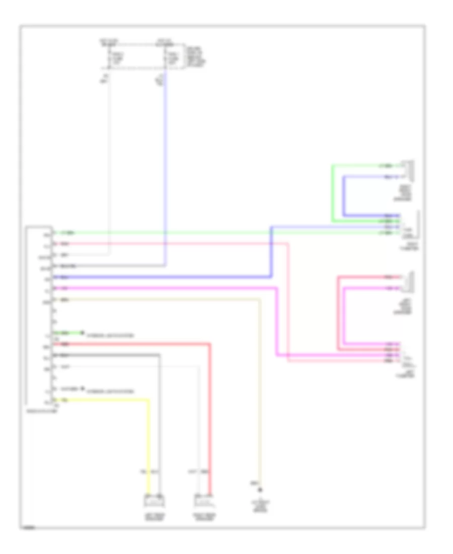
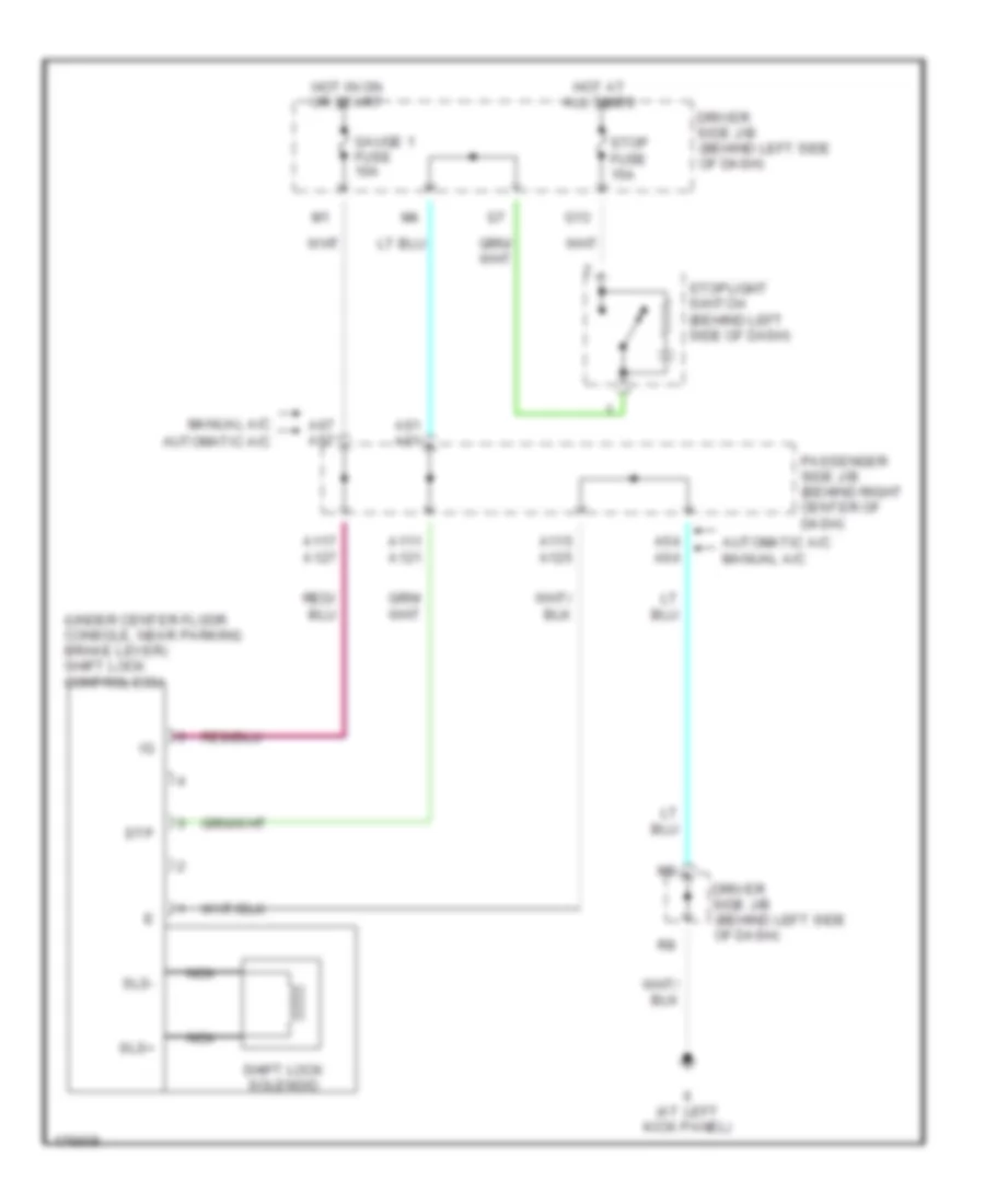
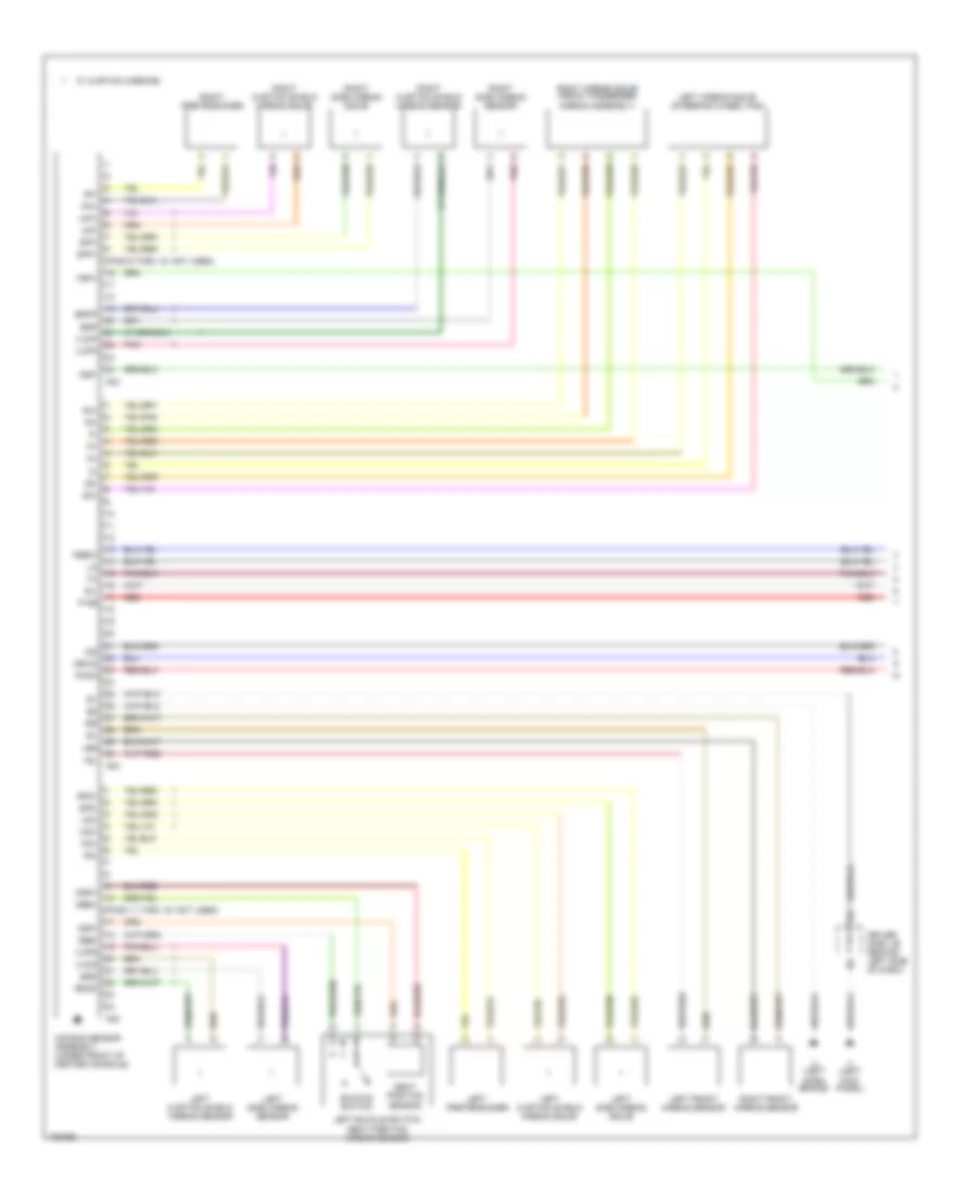
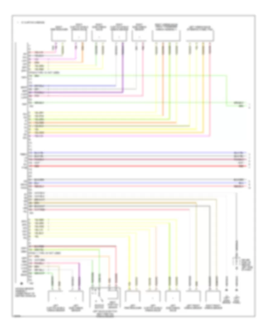
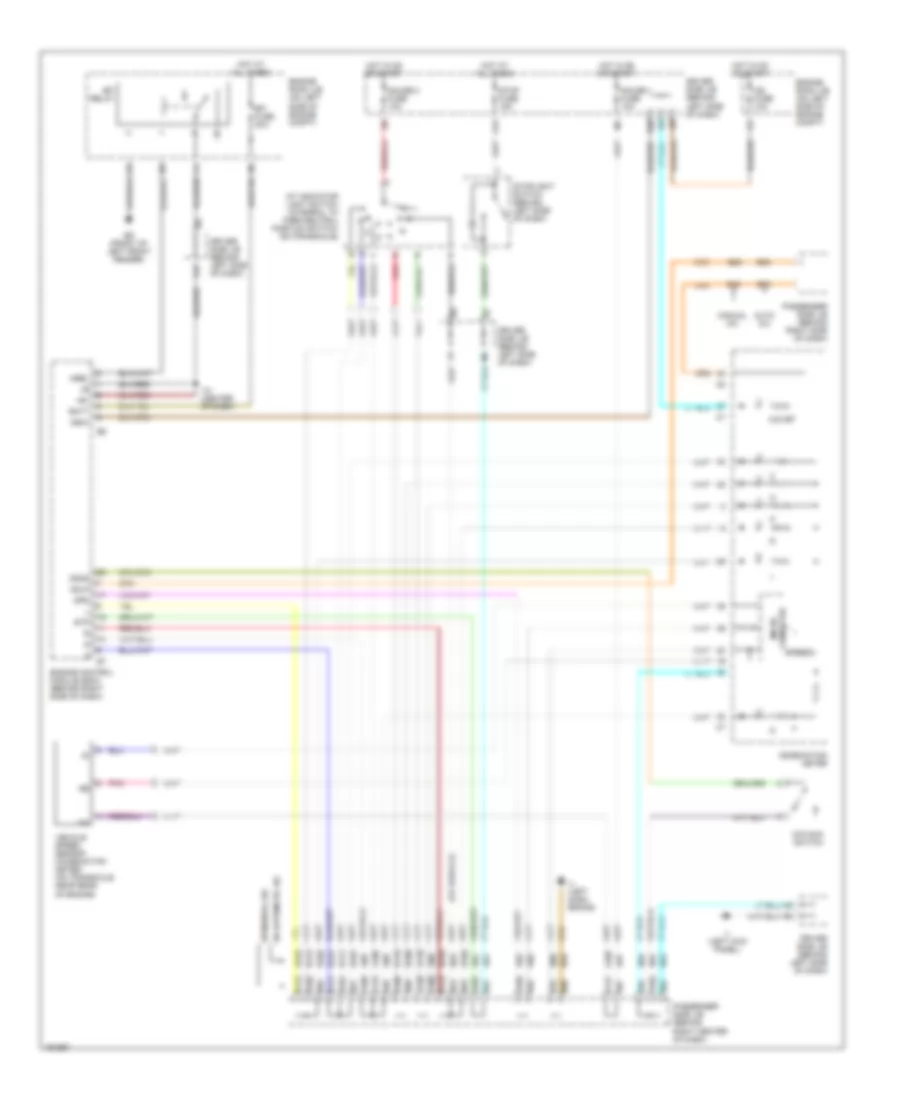
2.4L, Automatic A/C Wiring Diagram (1 of 2) for Toyota Camry LE 2004
 https://portal-diagnostov.com/license.html
Automotive Electricians Portal FZCO
Automotive Electricians Portal FZCO
https://portal-diagnostov.com/license.html
https://portal-diagnostov.com/license.html
Automotive Electricians Portal FZCO
Automotive Electricians Portal FZCO
List of elements for 2.4L, Automatic A/C Wiring Diagram (1 of 2) for Toyota Camry LE 2004:
- (at left kick panel) ii
- (at right dash reinforcement) in
- (left front of engine compartment) ec
- A/c ambient temperature sensor (at left front of engine compt)
- A/c control assembly (behind center of dash)
- A/c room temperature sensor (behind center of dash)
- A/c solar sensor (on top left side of dash)
- A/c thermistor (right side of dash)
- A/ci
- A/cs
- A14
- A26
- A54
- A56
- Ac1
- Aif
- Air
- Air inlet control servo motor (behind right side of dash)
- Air mix control servo motor (behind right side of dash)
- Air vent mode servo motor (behind center of dash)
- Amc
- Amh
- Aod
- Aof
- Blower motor (behind right side of dash)
- Blower motor controller (behind right side of dash)
- Blw
- Clock
- Data
- Def
- Defogger system
- Driver side j/b (behind left side of dash)
- Eb (right front of engine compartment)
- Ecu-b fuse 10a
- Engine room j/b (on left side of engine compartment)
- Engine room r/b (on left side of engine compartment)
- Exterior lights system interior lights system
- Face
- Gnd
- Hot at all times
- Htr fuse 50a
- Htr relay
- I2 (in dash harness, at right side of dash)
- Ig+
- Illum
- Interior lights system
- Mfrs
- Mrec
- Passenger side j/b (behind right center of dash)
- Pnk
- Pressure switch (right front of engine compartment)
- Psw
- Rdef
- S5-1
- S5-2
- S5-3
- Sg-1
- Sg-2
- Sg-3
- Sg-5
- Spd
- Sw1
- Tam
- Th+
- Tpi
- Tpm
- Tpo
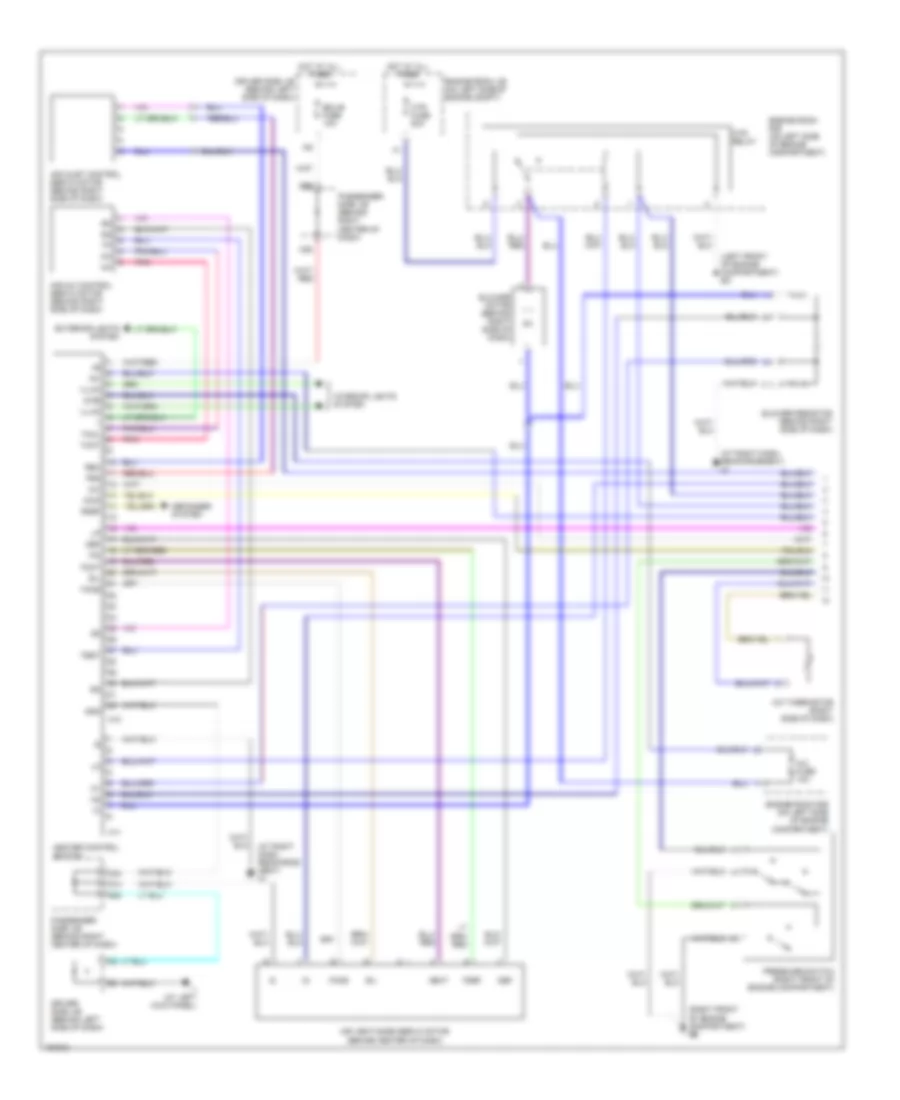
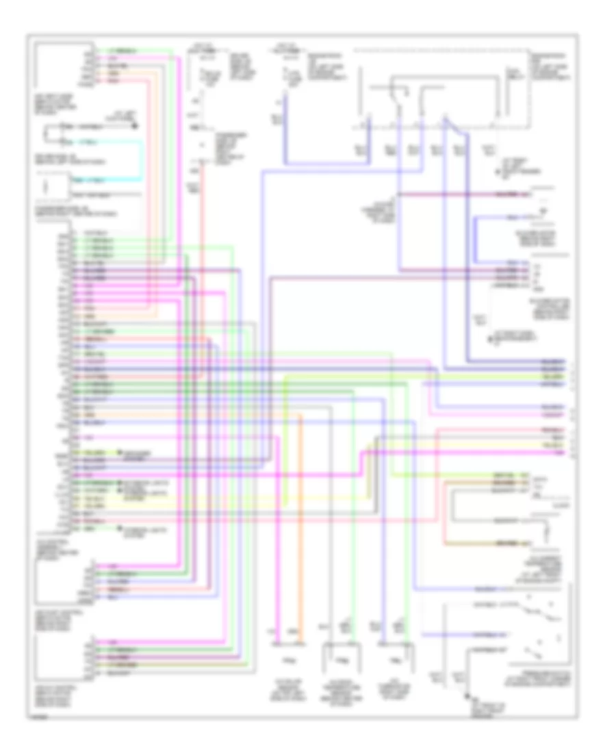
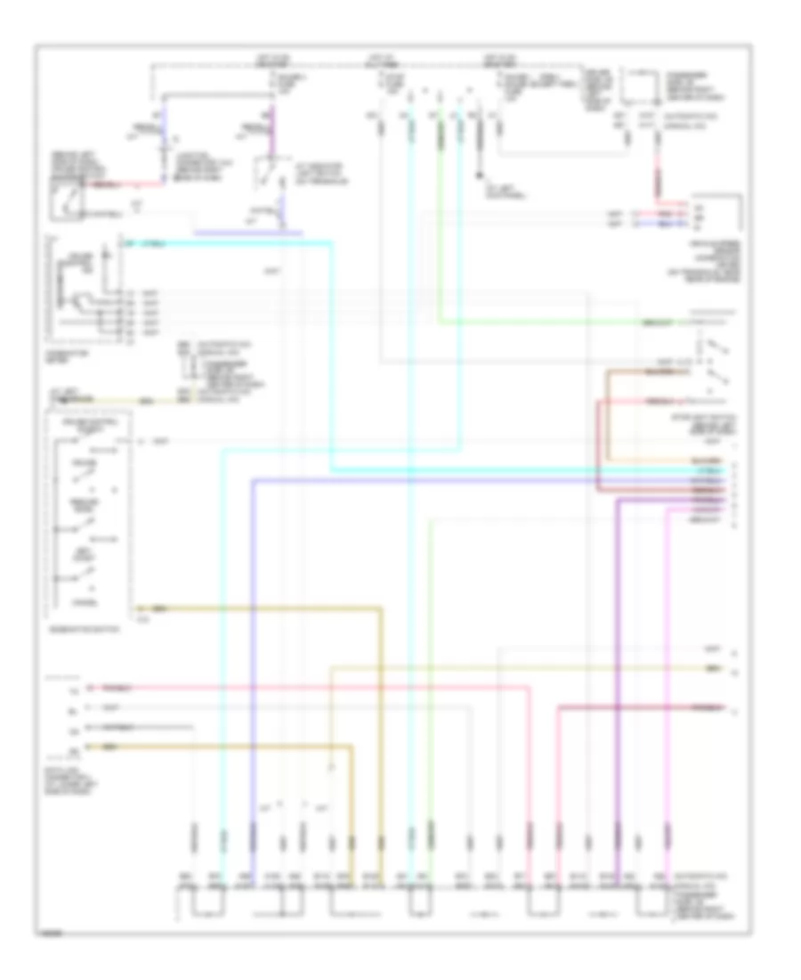
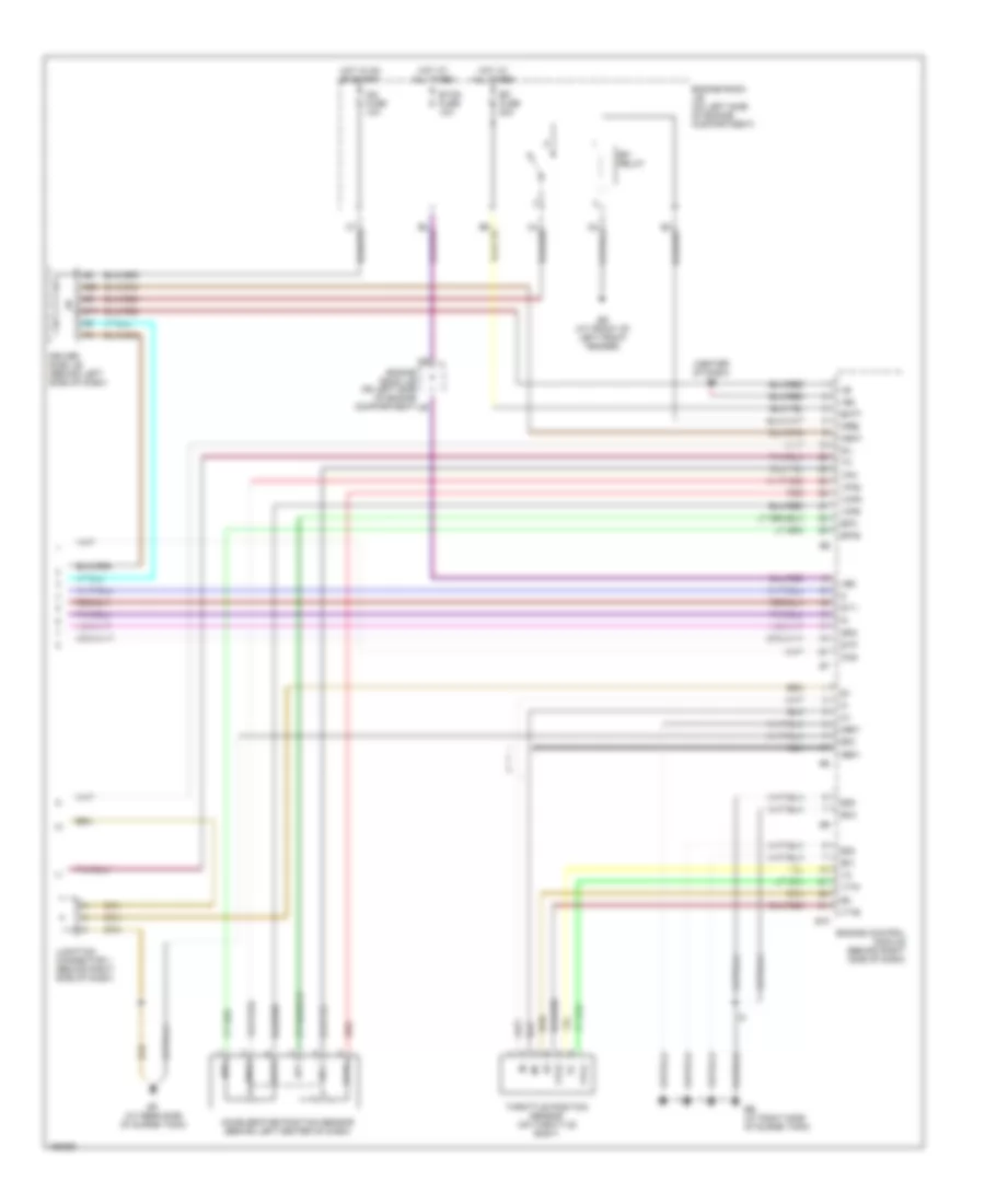
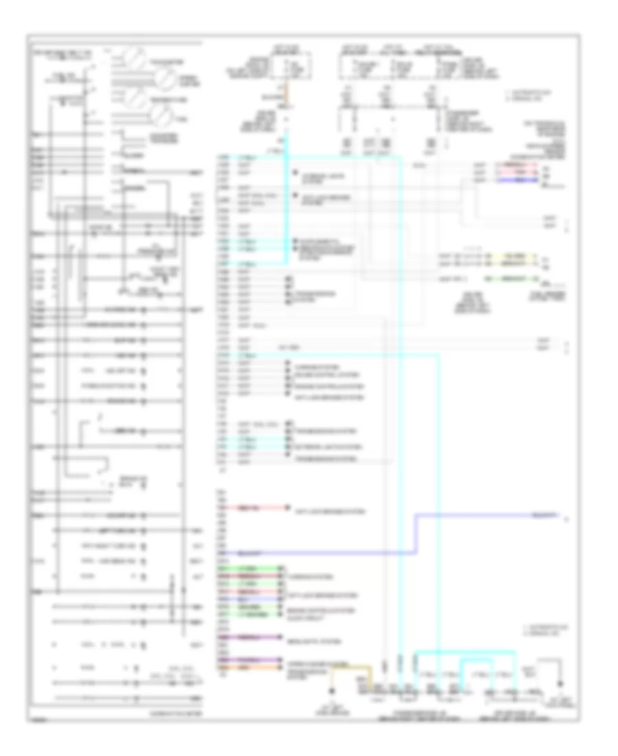
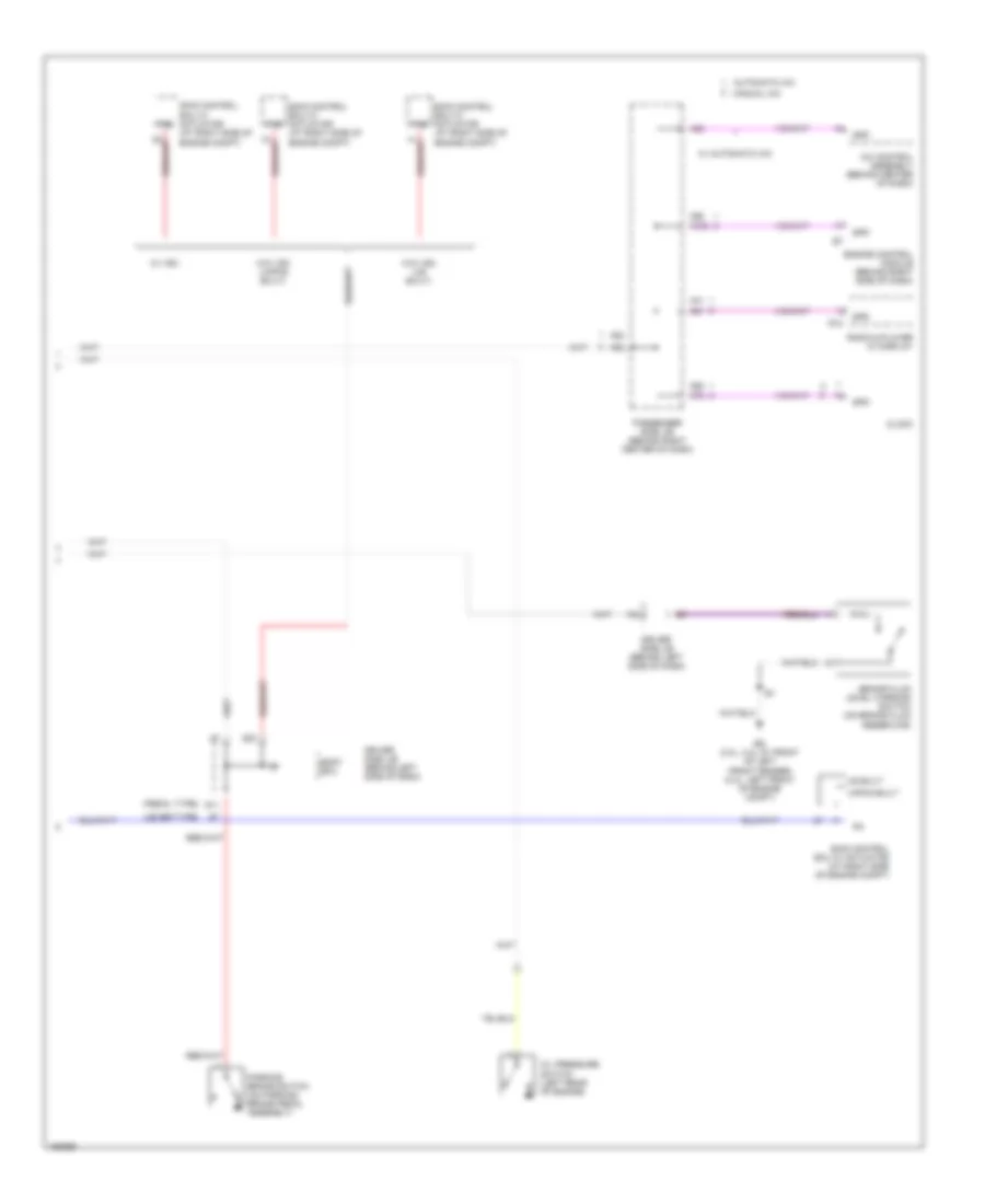
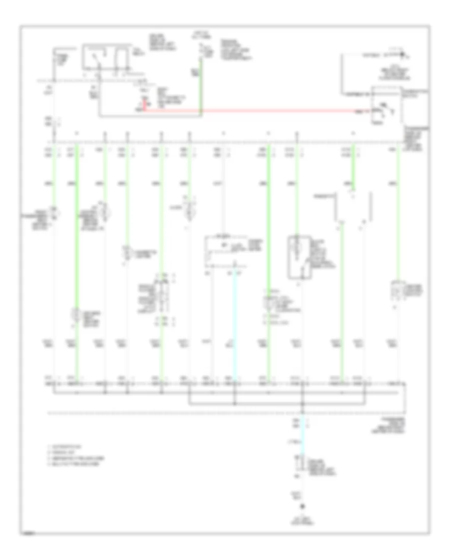
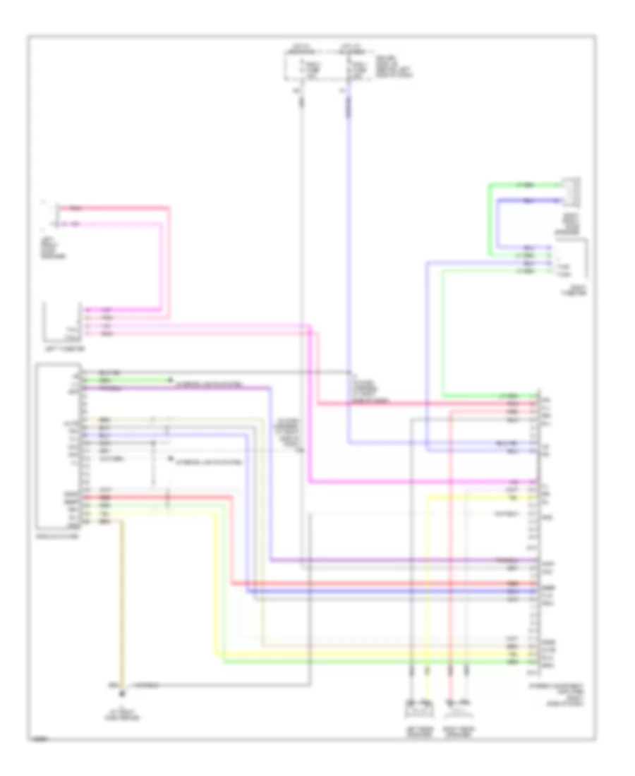
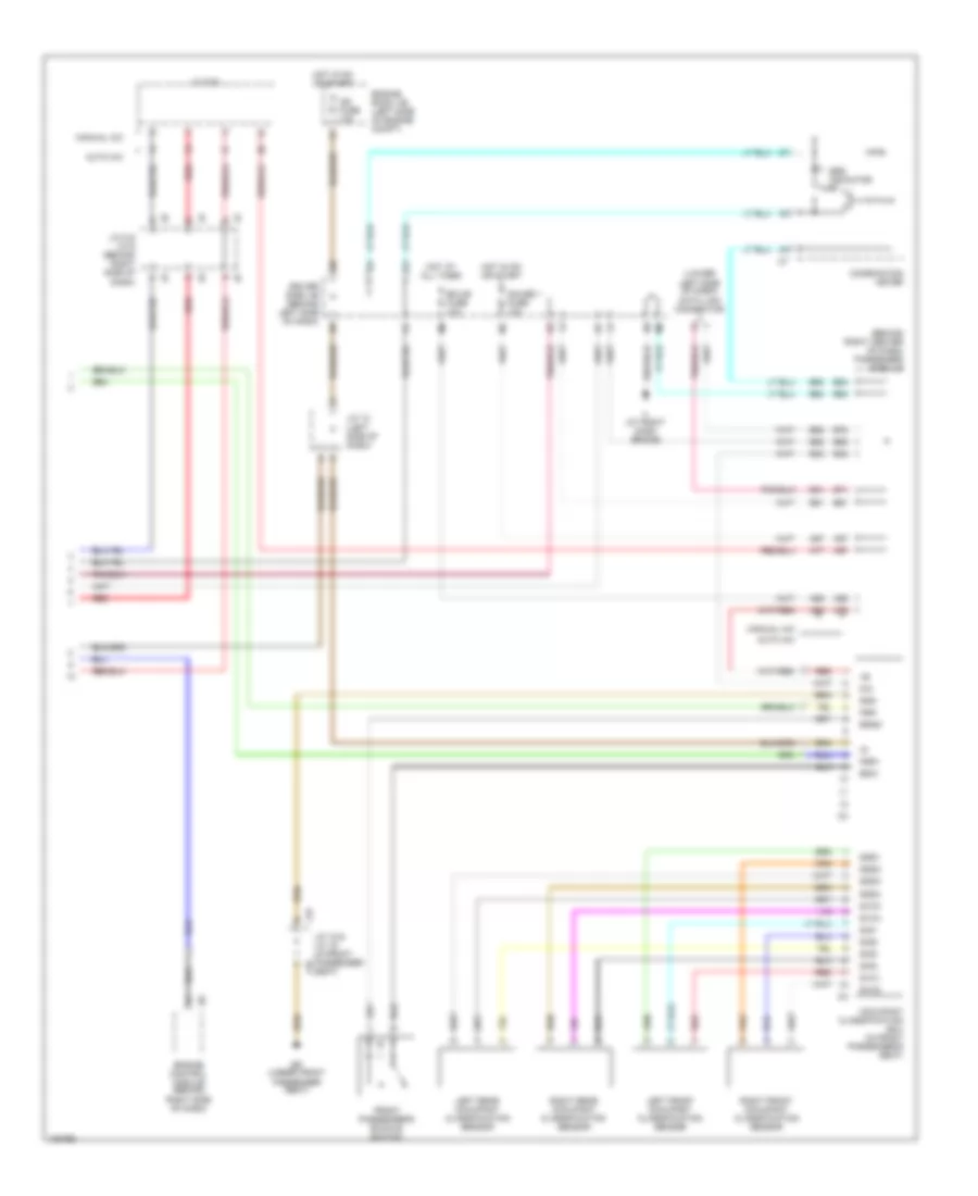
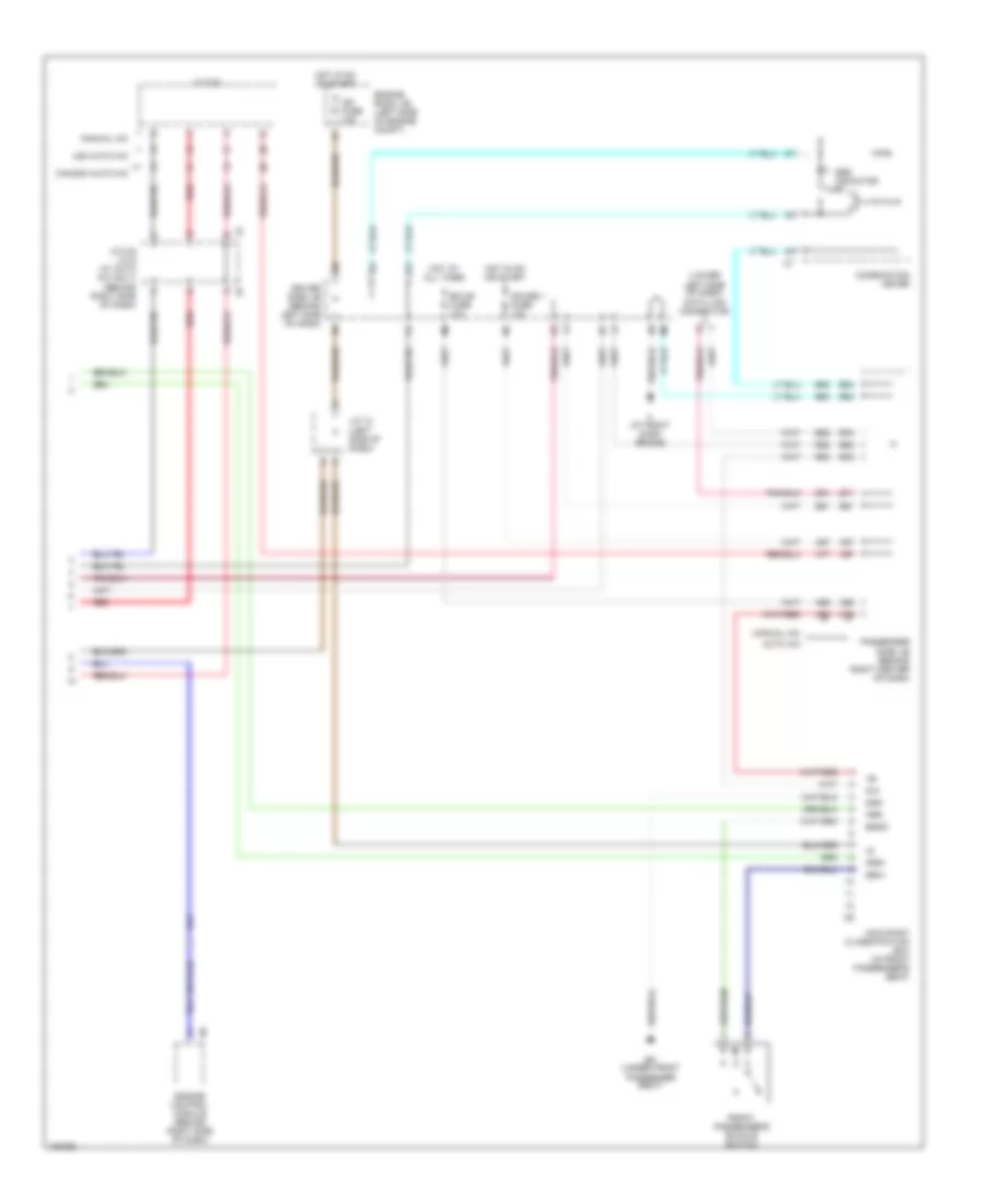
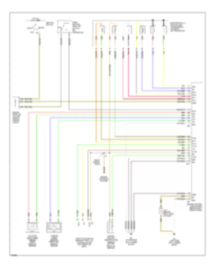
2.4L, Automatic A/C Wiring Diagram (2 of 2) for Toyota Camry LE 2004
List of elements for 2.4L, Automatic A/C Wiring Diagram (2 of 2) for Toyota Camry LE 2004:
- (behind right side of dash) theft deterrent ecu
- (in dash harness, at right side of dash)
- (in dash harness, at right side of dash) i8
- (left front of engine compt) ec
- (not used)
- A/c condenser fan motor (at front center of engine compartment)
- A/c lock sensor & a/c magnetic clutch (on left front side of engine)
- A/ci
- A/cs
- A22
- A29
- A36
- A59
- A82
- A92
- Acmg
- B118
- B124
- B125
- B129
- B14
- B34
- B44
- Cds fuse 30a
- Clutch
- Combination meter
- Diode (a/c 1) (left side of engine compartment)
- Diode (a/c 2) (left side of engine compartment)
- Driver side j/b (behind left side of dash)
- E10
- Ed (left front of engine compartment)
- Eg (at left side of cylinder bank)
- Engine control module (behind right side of dash)
- Engine controls system
- Engine coolant temperature sensor (on top rear of engine)
- Engine room j/b (on left side of engine compartment)
- Engine room j/b (on left side of engine compt)
- Engine room r/b (on left side of engine compartment)
- Except pzev
- Fan 1 relay
- Fan 2 relay
- Fan 3 relay
- Fan rly fuse 10a
- G24
- H10
- Hot at all times
- Hot in on or start
- Htr fuse 10a
- Imld
- Japan production
- Junction connector 1 (behind right side of dash)
- K10
- Lck1
- Lock sensor
- Mg clt relay
- Passenger side j/b (behind right center of dash)
- Pr2
- Pre
- Pzev
- Radiator fan motor (left front of engine compt)
- Rdi fuse 30a
- Red
- Spd
- Thr
- Thw
- Thwo
- Transponder key computer (on right side of steering column)
- Us production
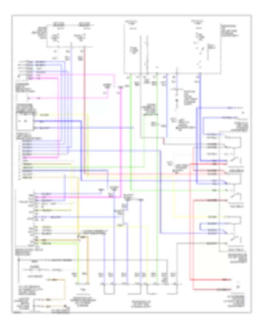
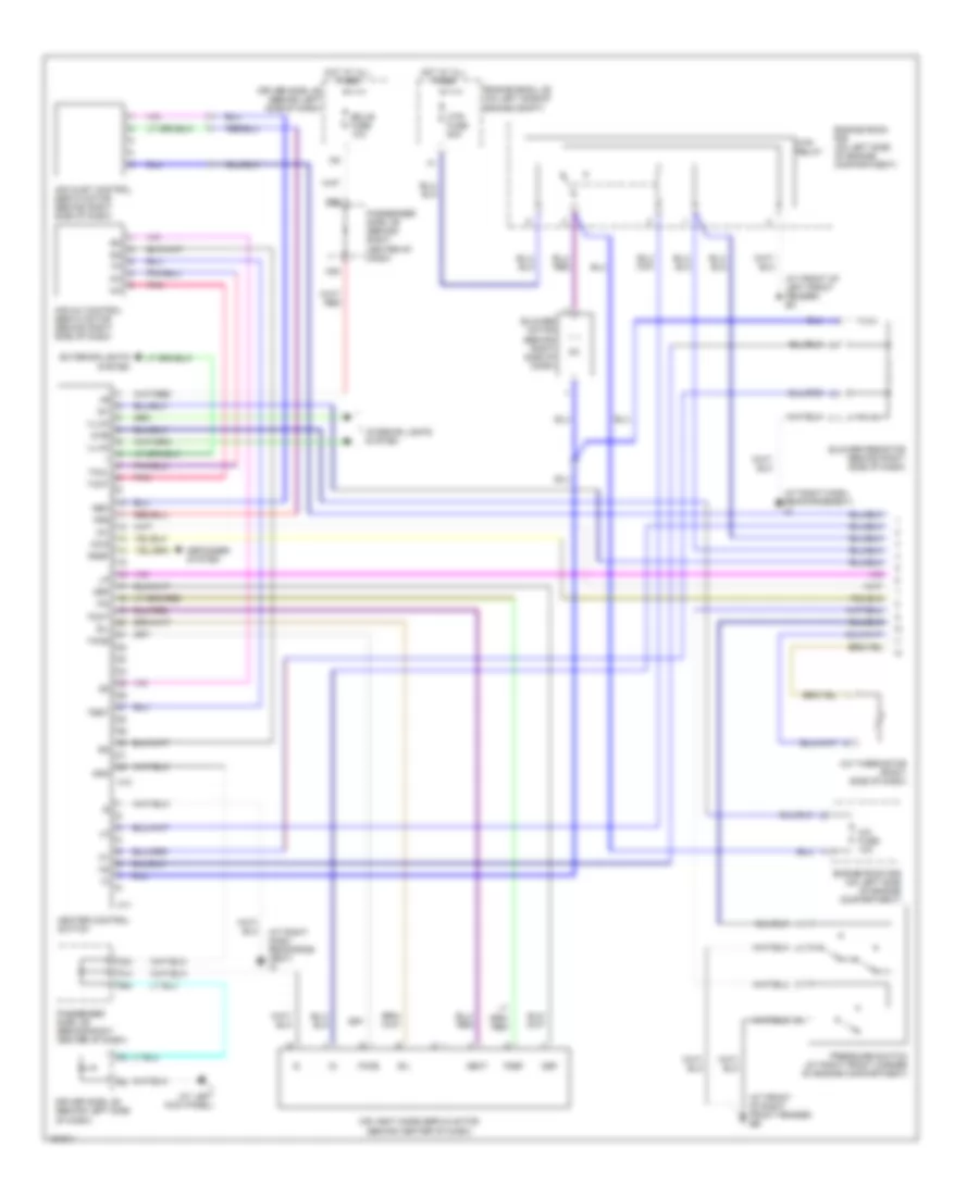
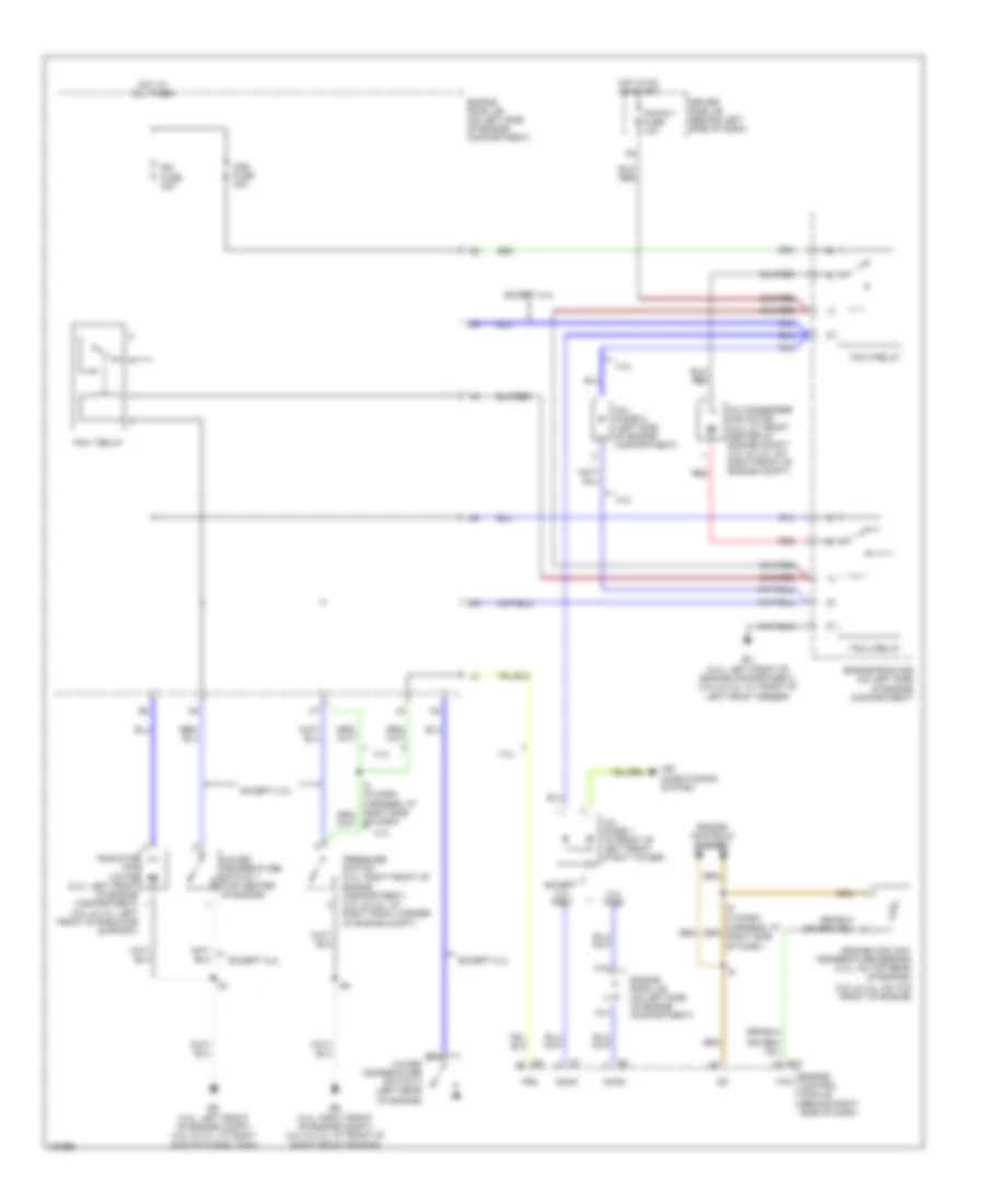
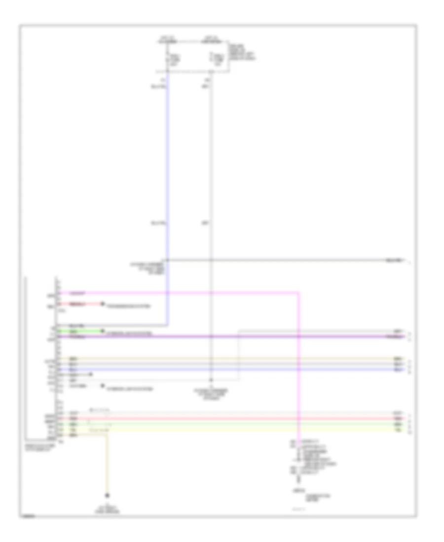
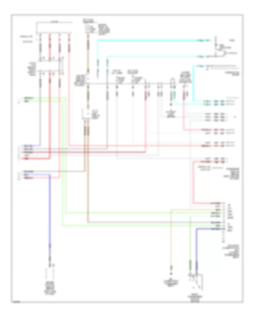
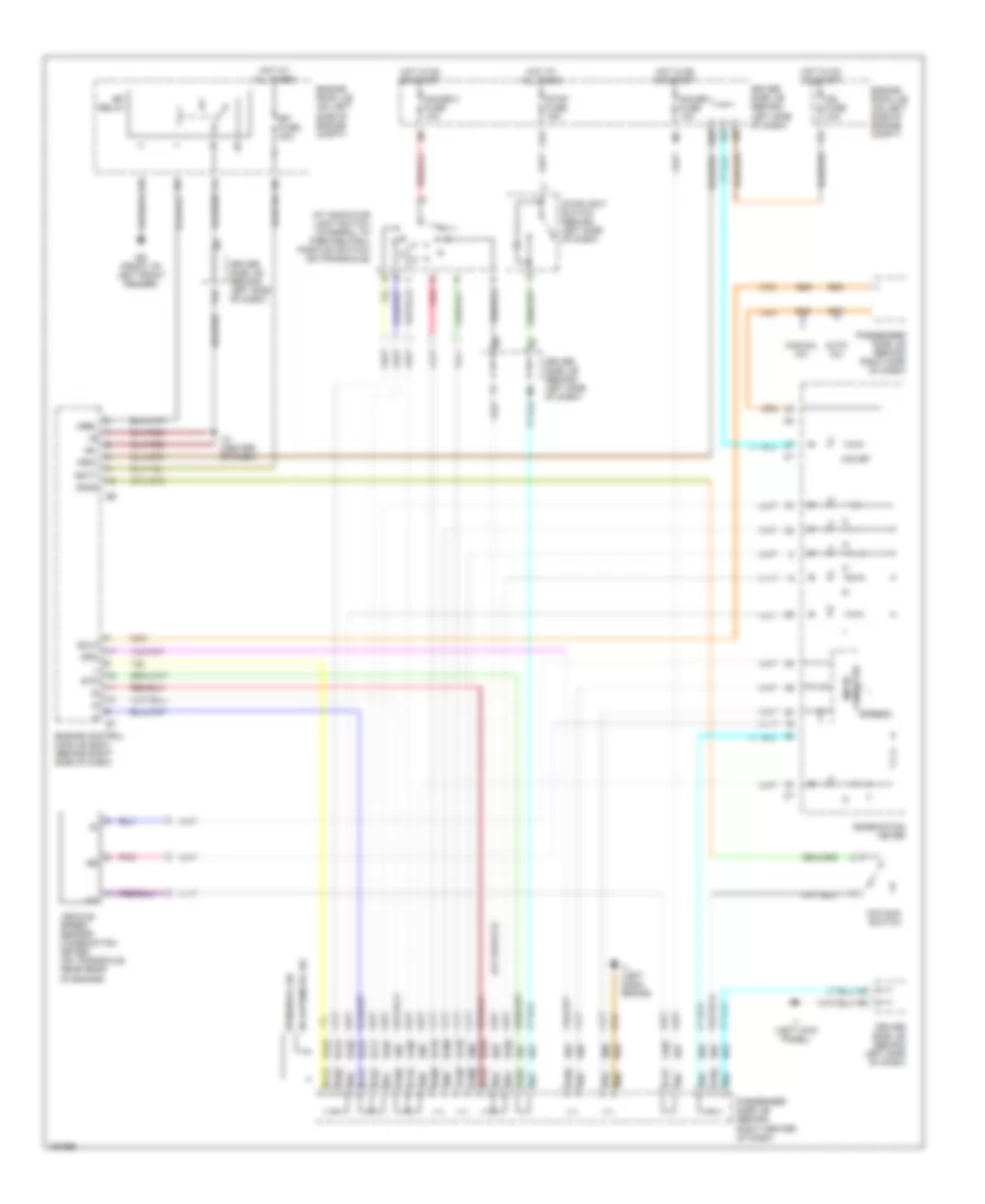
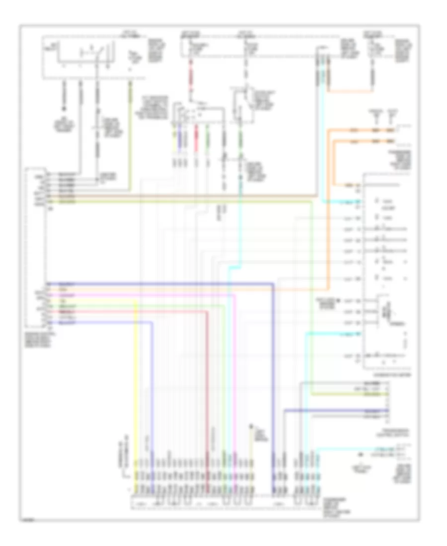
2.4L, Manual A/C Wiring Diagram (1 of 2) for Toyota Camry LE 2004
List of elements for 2.4L, Manual A/C Wiring Diagram (1 of 2) for Toyota Camry LE 2004:
- (at right dash reinforce- ment) in
- (at right dash reinforcement) in
- (left front of engine compartment) ec
- (right front of engine compartment) eb
- A/c
- A/c fuse 10a
- A/c thermistor (right side of dash)
- A/cb
- A14
- A34
- A36
- A64
- A66
- Acid
- Air inlet control servo motor (behind right side of dash)
- Air mix control servo motor (behind right side of dash)
- Air vent mode servo motor (behind center of dash)
- B/l
- Blower motor (behind right side of dash)
- Blower resistor (behind right side of dash)
- Def
- Defogger system
- Driver side j/b (behind left side of dash)
- Ecu-b fuse 10a
- Engine room j/b (on left side of engine compt)
- Engine room r/b (on left side of engine compartment)
- Exterior lights system
- F/d
- Face
- Fdef
- Foot
- Frs
- Gnd
- H10
- H11
- Heat
- Heater control switch
- Hot at all times
- Htr fuse 50a
- Htr relay
- Ig+
- Ii (at left kick panel)
- Illum
- Interior lights system
- Passenger side j/b (behind right center of dash)
- Pnk
- Pressure switch (right front of engine compartment)
- Rdef
- Rec
- Tcol
- Test
- Thot
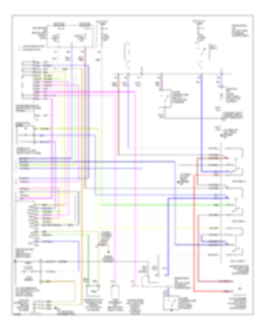
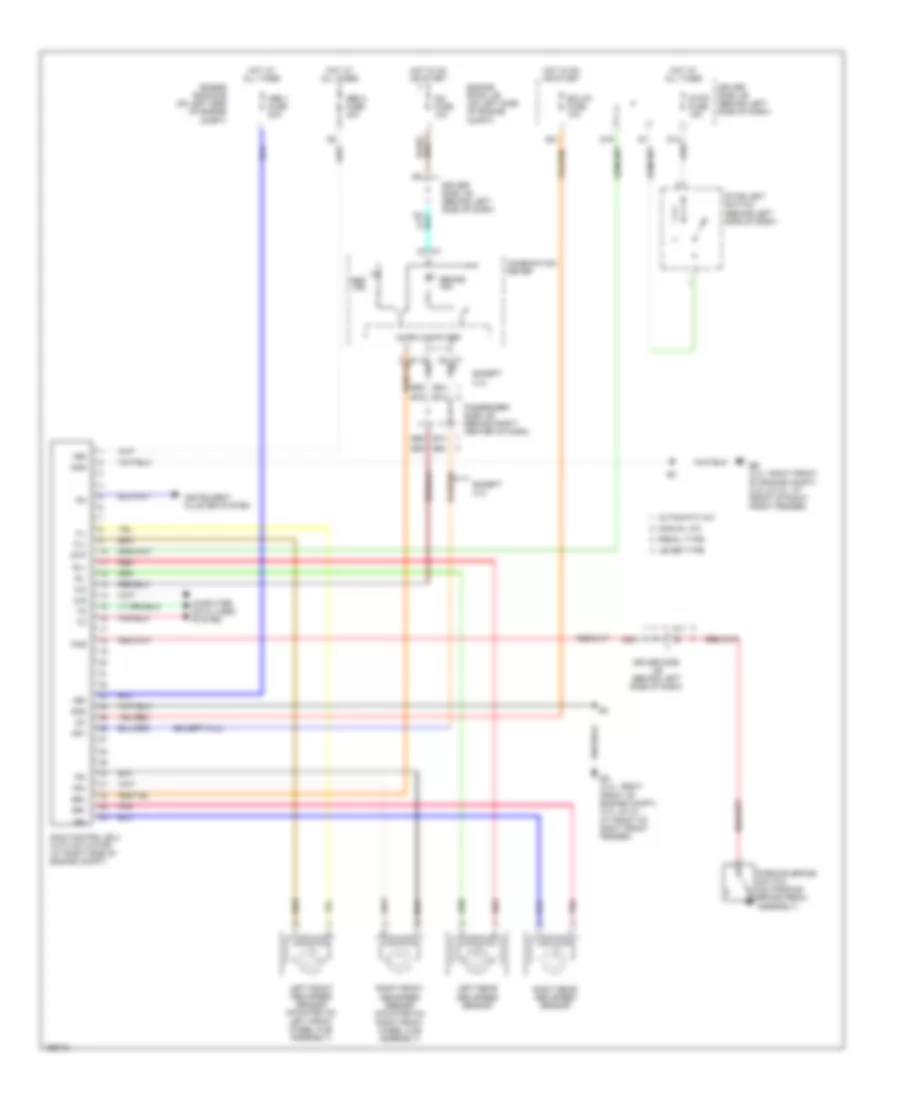
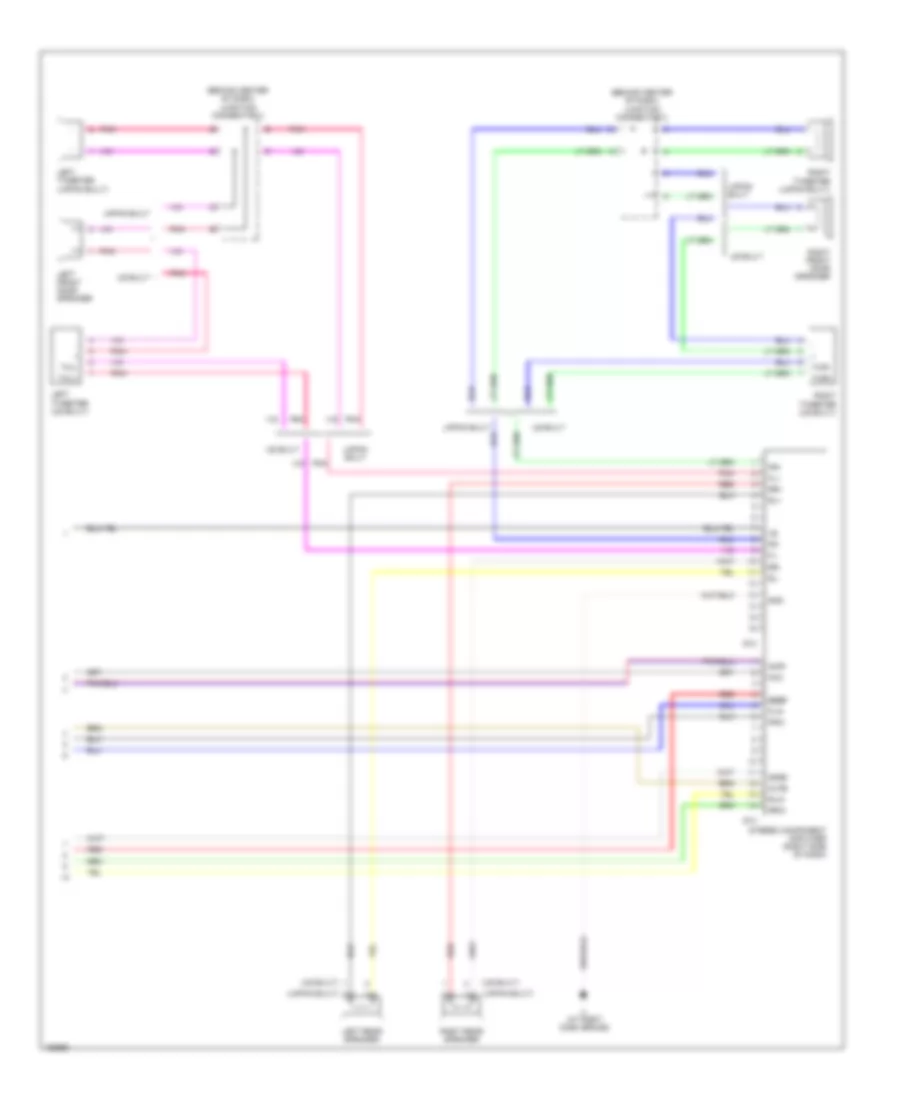
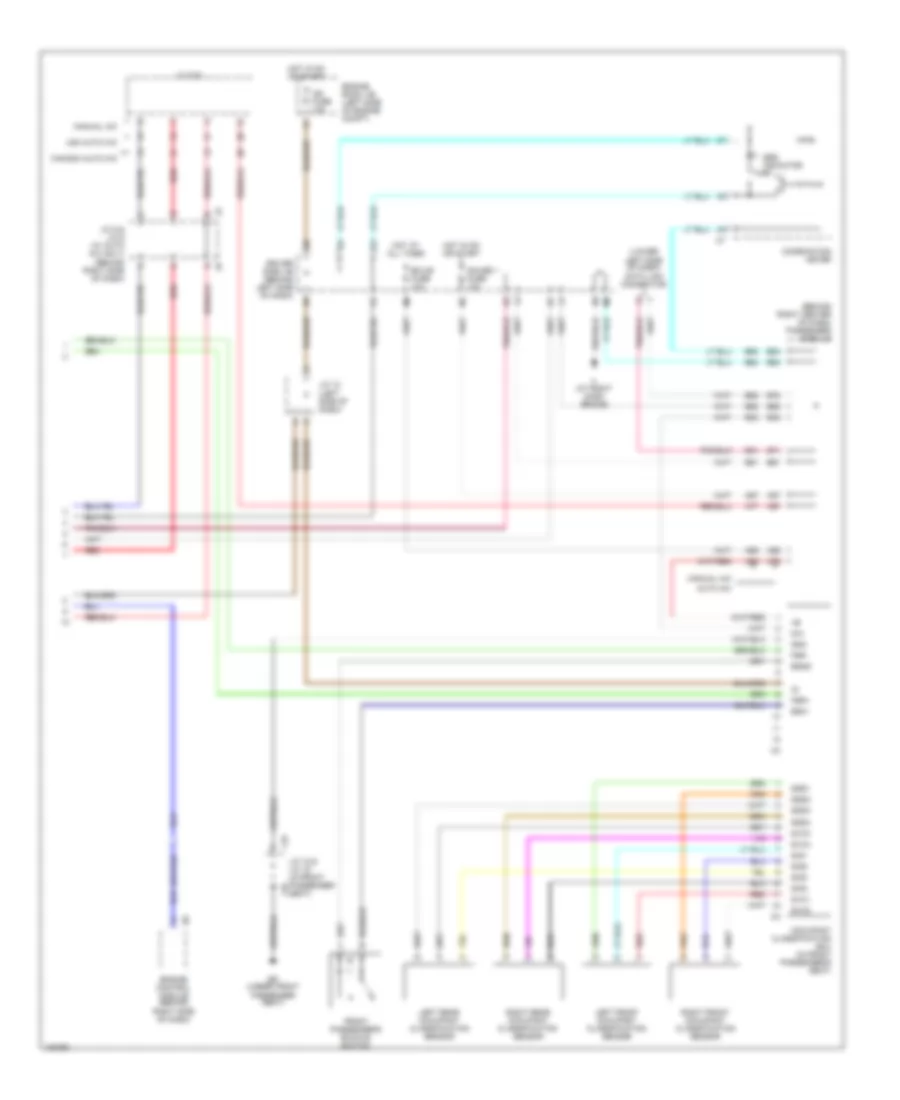
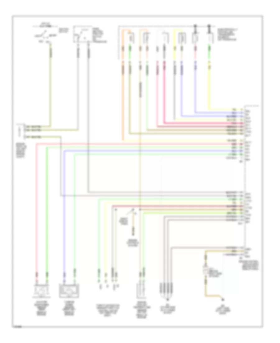
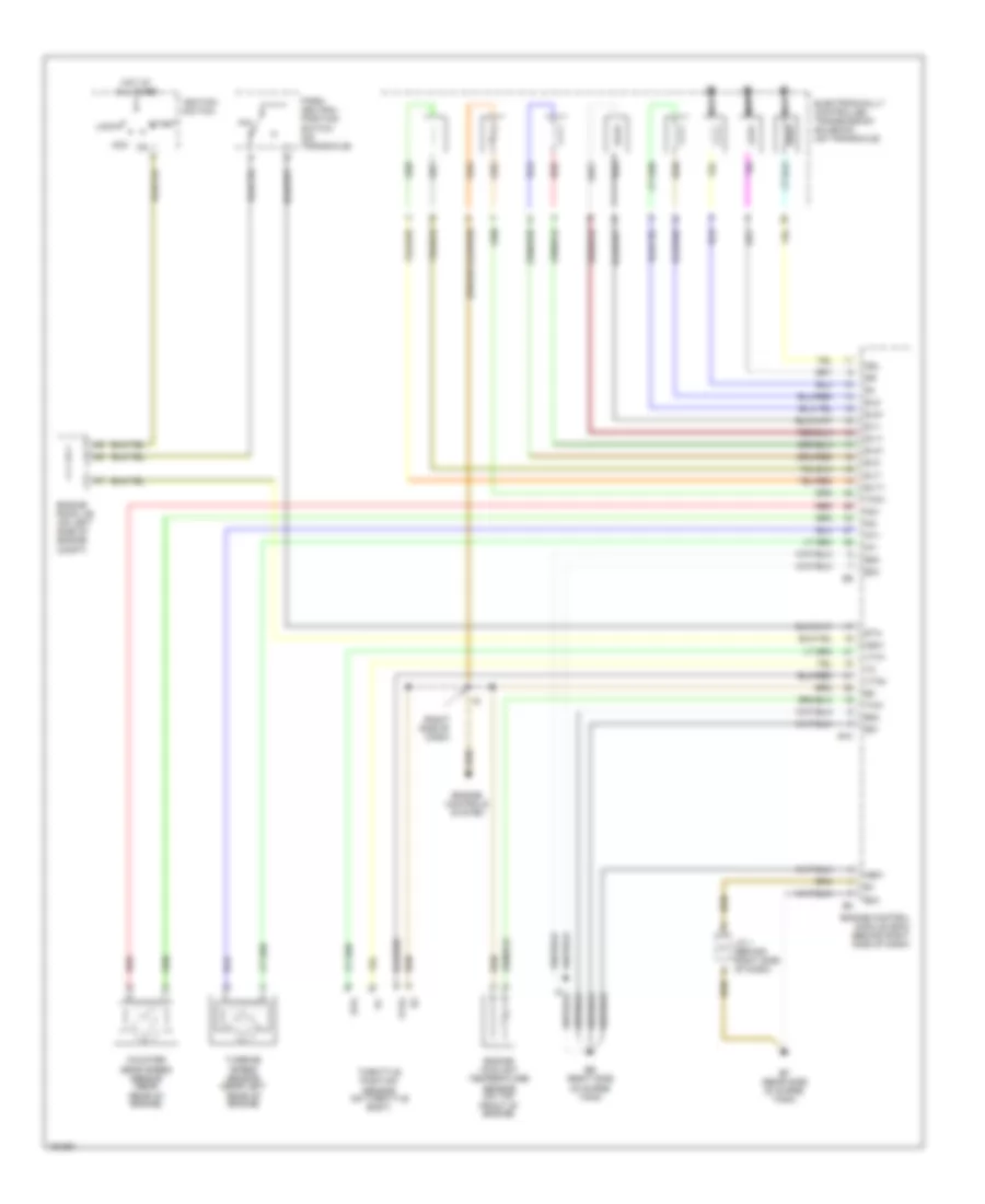
2.4L, Manual A/C Wiring Diagram (2 of 2) for Toyota Camry LE 2004
List of elements for 2.4L, Manual A/C Wiring Diagram (2 of 2) for Toyota Camry LE 2004:
- (in dash harness, at right side of dash)
- (left front of engine compartment) ed
- (left front of engine compt) ec
- (not used)
- A/c condenser fan motor (at front center of engine compartment)
- A/c lock sensor & a/c magnetic clutch (on left front side of engine)
- A/ci
- A/cs
- A19
- A20
- A39
- A69
- Acmg
- B24
- B34
- Cds fuse 30a
- Clutch
- Diode (a/c 1) (left side of engine compartment)
- Diode (a/c 2) (left side of engine compartment)
- Driver side j/b (behind left side of dash)
- E10
- Eg (at left side of cylinder bank)
- Engine control module (behind right side of dash)
- Engine coolant temperature sensor (on top rear of engine)
- Engine room j/b (on left side of engine compartment)
- Engine room j/b (on left side of engine compt)
- Engine room r/b (on left side of engine compartment)
- Except pzev
- Fan 1 relay
- Fan 2 relay
- Fan 3 relay
- Fan rly fuse 10a
- G24
- H10
- Hot at all times
- Hot in on or start
- Htr fuse 10a
- Imld
- Junction connector 1 (behind right side of dash)
- K10
- Lck1
- Lock sensor
- Mg clt relay
- Passenger side j/b (behind right center of dash)
- Pr2
- Pre
- Pzev
- Radiator fan motor (left front of engine compt)
- Rdi fuse 30a
- Red
- The (or thr)
- Thw
- Transponder key computer (on right side of steering column)
3.0L
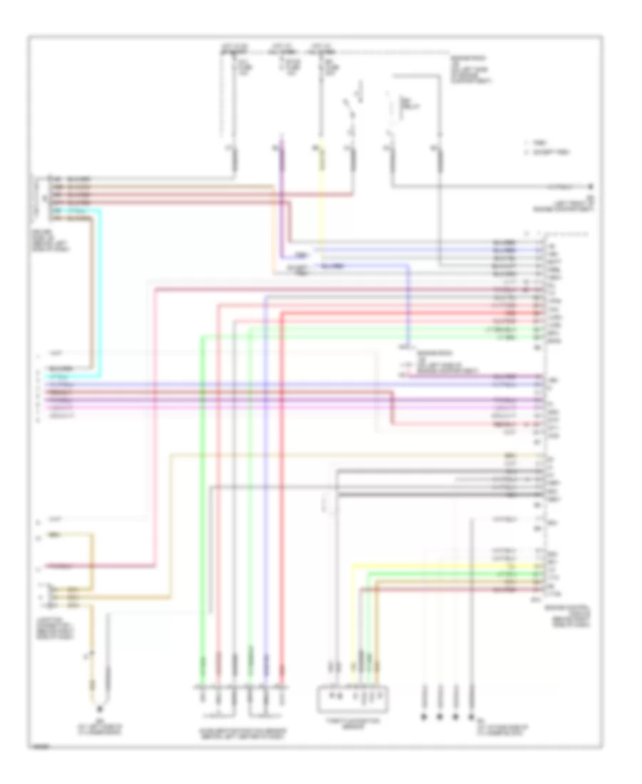
3.0L, Automatic A/C Wiring Diagram (1 of 2) for Toyota Camry LE 2004
List of elements for 3.0L, Automatic A/C Wiring Diagram (1 of 2) for Toyota Camry LE 2004:
- (at front of left front fender) ec
- (at left kick panel) ii
- (at right dash reinforcement) in
- A/c ambient temperature sensor (at left front of engine compt)
- A/c control assembly (behind center of dash)
- A/c room temperature sensor (behind center of dash)
- A/c solar sensor (on top left side of dash)
- A/c thermistor (right side of dash)
- A/ci
- A/cs
- A14
- A26
- A54
- A56
- Ac1
- Aif
- Air
- Air inlet control servo motor (behind right side of dash)
- Air mix control servo motor (behind right side of dash)
- Air vent mode servo motor (behind center of dash)
- Amc
- Amh
- Aod
- Aof
- Blower motor (behind right side of dash)
- Blower motor controller (behind right side of dash)
- Blw
- Clock
- Data
- Def
- Defogger system
- Driver side j/b (behind left side of dash)
- Eb (at front of right front fender)
- Ecu-b fuse 10a
- Engine room j/b (on left side of engine compartment)
- Engine room r/b (on left side of engine compartment)
- Exterior lights system interior lights system
- Face
- Gnd
- Hot at all times
- Htr fuse 50a
- Htr relay
- I2 (in dash harness, at right side of dash)
- Ig+
- Illum
- Interior lights system
- Mfrs
- Mrec
- Passenger side j/b (behind right center of dash)
- Pnk
- Pressure switch (at right front corner of engine compartment)
- Psw
- Rdef
- S5-1
- S5-2
- S5-3
- Sg-1
- Sg-2
- Sg-3
- Sg-5
- Spd
- Sw1
- Tam
- Th+
- Tpi
- Tpm
- Tpo
3.0L, Automatic A/C Wiring Diagram (2 of 2) for Toyota Camry LE 2004
List of elements for 3.0L, Automatic A/C Wiring Diagram (2 of 2) for Toyota Camry LE 2004:
- (at front of left front fender) ec
- (at front of left front fender) ed
- (in dash harness, at right side of dash)
- (in engine compt harness, behind right headlight) e1
- A/c condenser fan motor (on right front of engine compartment)
- A/c lock sensor & a/c magnetic clutch (on left front side of engine)
- A/ci
- A/cs
- A22
- A29
- A36
- A59
- A82
- A92
- Acmg
- B118
- B124
- B125
- B129
- B14
- B34
- B44
- Cds fuse 30a
- Clutch
- Combination meter
- Diode (a/c 1) (in front of left front strut tower)
- Driver side j/b (behind left side of dash)
- E10
- Ef (at rear side of surge tank)
- Engine control module (behind right side of dash)
- Engine controls system
- Engine coolant temperature sensor (on top front of engine)
- Engine room j/b (on left side of engine compartment)
- Engine room r/b (on left side of engine compartment)
- Fan 1 relay
- Fan 2 relay
- Fan 3 relay
- Fan rly fuse 10a
- G24
- Hot at all times
- Hot in on or start
- Htr fuse 10a
- Japan production
- Junction connector 1 (behind right side of dash)
- Lck1
- Lock sensor
- Mg clt relay
- Passenger side j/b (behind right center of dash)
- Pre
- Radiator fan motor (left front of radiator support)
- Rdi fuse 30a
- Red
- Spd
- Theft deterrent ecu (behind right side of dash)
- Thr
- Thw
- Thwo
- Transponder key computer (on right side of steering column)
- Us production
- Water temperature switch 1 (top center of engine)
- Water temperature switch 2 (left rear of engine)
3.0L, Manual A/C Wiring Diagram (1 of 2) for Toyota Camry LE 2004
List of elements for 3.0L, Manual A/C Wiring Diagram (1 of 2) for Toyota Camry LE 2004:
- (at front of left front fender) ec
- (at front of right front fender) eb
- (at right dash reinforce- ment) in
- (at right dash reinforcement) in
- A/c
- A/c fuse 10a
- A/c thermistor (right side of dash)
- A/cb
- A14
- A34
- A36
- A64
- A66
- Acid
- Air inlet control servo motor (behind right side of dash)
- Air mix control servo motor (behind right side of dash)
- Air vent mode servo motor (behind center of dash)
- B/l
- Blower motor (behind right side of dash)
- Blower resistor (behind right side of dash)
- Def
- Defogger system
- Driver side j/b (behind left side of dash)
- Ecu-b fuse 10a
- Engine room j/b (on left side of engine compt)
- Engine room r/b (on left side of engine compartment)
- Exterior lights system
- F/d
- Face
- Fdef
- Foot
- Frs
- Gnd
- H10
- H11
- Heat
- Heater control switch
- Hot at all times
- Htr fuse 50a
- Htr relay
- Ig+
- Ii (at left kick panel)
- Illum
- Interior lights system
- Passenger side j/b (behind right center of dash)
- Pnk
- Pressure switch (at right front corner of engine compartment)
- Rdef
- Rec
- Tcol
- Test
- Thot
3.0L, Manual A/C Wiring Diagram (2 of 2) for Toyota Camry LE 2004
List of elements for 3.0L, Manual A/C Wiring Diagram (2 of 2) for Toyota Camry LE 2004:
- (at front of left front fender) ec
- (at front of left front fender) ed
- (in dash harness, at right side of dash)
- A/c condenser fan motor (on right front of engine compartment)
- A/c lock sensor & a/c magnetic clutch (on left front side of engine)
- A/ci
- A/cs
- A19
- A20
- A39
- A69
- Acmg
- B24
- B34
- Cds fuse 30a
- Clutch
- Diode (a/c 1) (in front of left front strut tower)
- Driver side j/b (behind left side of dash)
- E10
- Ef (at rear side of surge tank)
- Engine control module (behind right side of dash)
- Engine coolant temperature sensor (on top front of engine)
- Engine room j/b (on left side of engine compartment)
- Engine room r/b (on left side of engine compartment)
- Fan 1 relay
- Fan 2 relay
- Fan 3 relay
- Fan rly fuse 10a
- G24
- Hot at all times
- Hot in on or start
- Htr fuse 10a
- Junction connector 1 (behind right side of dash)
- Lck1
- Lock sensor
- Mg clt relay
- Passenger side j/b (behind right center of dash)
- Pre
- Radiator fan motor (left front of radiator support)
- Rdi fuse 30a
- Red
- The
- Thw
- Transponder key computer (on right side of steering column)
- Water temperature switch 1 (top center of engine)
- Water temperature switch 2 (left rear of engine)
3.3L
3.3L, Automatic A/C Wiring Diagram (1 of 2) for Toyota Camry LE 2004
List of elements for 3.3L, Automatic A/C Wiring Diagram (1 of 2) for Toyota Camry LE 2004:
- (at front of left front fender) ec
- (at left kick panel) ii
- (at right dash reinforcement) in
- A/c ambient temperature sensor (at left front of engine compt)
- A/c control assembly (behind center of dash)
- A/c room temperature sensor (behind center of dash)
- A/c solar sensor (on top left side of dash)
- A/c thermistor (right side of dash)
- A/ci
- A/cs
- A14
- A26
- A54
- A56
- Ac1
- Aif
- Air
- Air inlet control servo motor (behind right side of dash)
- Air mix control servo motor (behind right side of dash)
- Air vent mode servo motor (behind center of dash)
- Amc
- Amh
- Aod
- Aof
- Blower motor (behind right side of dash)
- Blower motor controller (behind right side of dash)
- Blw
- Clock
- Data
- Def
- Defogger system
- Driver side j/b (behind left side of dash)
- Eb (at front of right front fender)
- Ecu-b fuse 10a
- Engine room j/b (on left side of engine compartment)
- Engine room r/b (on left side of engine compartment)
- Exterior lights system interior lights system
- Face
- Gnd
- Hot at all times
- Htr fuse 50a
- Htr relay
- I2 (in dash harness, at right side of dash)
- Ig+
- Illum
- Interior lights system
- Mfrs
- Mrec
- Passenger side j/b (behind right center of dash)
- Pnk
- Pressure switch (at right front corner of engine compartment)
- Psw
- Rdef
- S5-1
- S5-2
- S5-3
- Sg-1
- Sg-2
- Sg-3
- Sg-5
- Spd
- Sw1
- Tam
- Th+
- Tpi
- Tpm
- Tpo
3.3L, Automatic A/C Wiring Diagram (2 of 2) for Toyota Camry LE 2004
List of elements for 3.3L, Automatic A/C Wiring Diagram (2 of 2) for Toyota Camry LE 2004:
- (at front of left front fender) ec
- (at front of left front fender) ed
- (in dash harness, at right side of dash)
- (in engine compt harness, behind right headlight) e1
- A/c condenser fan motor (on right front of engine compartment)
- A/c lock sensor & a/c magnetic clutch (on left front side of engine)
- A/ci
- A/cs
- A22
- A29
- A36
- A59
- A82
- A92
- Acmg
- B118
- B124
- B125
- B129
- B14
- B34
- B44
- Cds fuse 30a
- Clutch
- Combination meter
- Diode (a/c 1) (in front of left front strut tower)
- Driver side j/b (behind left side of dash)
- E10
- Ef (at rear side of surge tank)
- Engine control module (behind right side of dash)
- Engine controls system
- Engine coolant temperature sensor (on top front of engine)
- Engine room j/b (on left side of engine compartment)
- Engine room r/b (on left side of engine compartment)
- Fan 1 relay
- Fan 2 relay
- Fan 3 relay
- Fan rly fuse 10a
- G24
- Hot at all times
- Hot in on or start
- Htr fuse 10a
- Japan production
- Junction connector 1 (behind right side of dash)
- Lck1
- Lock sensor
- Mg clt relay
- Passenger side j/b (behind right center of dash)
- Pre
- Radiator fan motor (left front of radiator support)
- Rdi fuse 30a
- Red
- Spd
- Theft deterrent ecu (behind right side of dash)
- Thr
- Thw
- Thwo
- Transponder key computer (on right side of steering column)
- Us production
- Water temperature switch 1 (top center of engine)
- Water temperature switch 2 (left rear of engine)
3.3L, Manual A/C Wiring Diagram (1 of 2) for Toyota Camry LE 2004
List of elements for 3.3L, Manual A/C Wiring Diagram (1 of 2) for Toyota Camry LE 2004:
- (at front of left front fender) ec
- (at front of right front fender) eb
- (at right dash reinforce- ment) in
- (at right dash reinforcement) in
- A/c
- A/c fuse 10a
- A/c thermistor (right side of dash)
- A/cb
- A14
- A34
- A36
- A64
- A66
- Acid
- Air inlet control servo motor (behind right side of dash)
- Air mix control servo motor (behind right side of dash)
- Air vent mode servo motor (behind center of dash)
- B/l
- Blower motor (behind right side of dash)
- Blower resistor (behind right side of dash)
- Def
- Defogger system
- Driver side j/b (behind left side of dash)
- Ecu-b fuse 10a
- Engine room j/b (on left side of engine compt)
- Engine room r/b (on left side of engine compartment)
- Exterior lights system
- F/d
- Face
- Fdef
- Foot
- Frs
- Gnd
- H10
- H11
- Heat
- Heater control switch
- Hot at all times
- Htr fuse 50a
- Htr relay
- Ig+
- Ii (at left kick panel)
- Illum
- Interior lights system
- Passenger side j/b (behind right center of dash)
- Pnk
- Pressure switch (at right front corner of engine compartment)
- Rdef
- Rec
- Tcol
- Test
- Thot
3.3L, Manual A/C Wiring Diagram (2 of 2) for Toyota Camry LE 2004
List of elements for 3.3L, Manual A/C Wiring Diagram (2 of 2) for Toyota Camry LE 2004:
- (at front of left front fender) ec
- (at front of left front fender) ed
- (in dash harness, at right side of dash)
- A/c condenser fan motor (on right front of engine compartment)
- A/c lock sensor & a/c magnetic clutch (on left front side of engine)
- A/ci
- A/cs
- A19
- A20
- A39
- A69
- Acmg
- B24
- B34
- Cds fuse 30a
- Clutch
- Diode (a/c 1) (in front of left front strut tower)
- Driver side j/b (behind left side of dash)
- E10
- Ef (at rear side of surge tank)
- Engine control module (behind right side of dash)
- Engine coolant temperature sensor (on top front of engine)
- Engine room j/b (on left side of engine compartment)
- Engine room r/b (on left side of engine compartment)
- Fan 1 relay
- Fan 2 relay
- Fan 3 relay
- Fan rly fuse 10a
- G24
- Hot at all times
- Hot in on or start
- Htr fuse 10a
- Junction connector 1 (behind right side of dash)
- Lck1
- Lock sensor
- Mg clt relay
- Passenger side j/b (behind right center of dash)
- Pre
- Radiator fan motor (left front of radiator support)
- Rdi fuse 30a
- Red
- The
- Thw
- Transponder key computer (on right side of steering column)
- Water temperature switch 1 (top center of engine)
- Water temperature switch 2 (left rear of engine)
ANTI-LOCK BRAKES
Anti-lock Brakes Wiring Diagram, Japan Production for Toyota Camry LE 2004
List of elements for Anti-lock Brakes Wiring Diagram, Japan Production for Toyota Camry LE 2004:
- (except 2.4l)
- +bm
- +bs
- Abs 1 fuse 50a
- Abs 2 fuse 40a
- Abs ind
- Automatic a/c
- B64
- B74
- B75
- B85
- B95
- Brake ind
- Brl
- Combination meter
- Computer data lines system
- D/g
- Driver side j/b (behind left side of dash)
- Ea (2.4l: right front of engine compt) (3.0l & 3.3l: at front of right front fender)
- Eb (2.4l: right front of engine compt) (3.0l & 3.3l: at front of right front fender)
- Ecu-ig fuse 10a
- Engine room j/b (on left side of engine compt)
- Engine room r/b (on left side of engine compt)
- Except 2.4l
- Fl+
- Fl-
- Fr+
- Fr-
- G11
- G13
- G19
- G21
- G23
- Gnd
- Hot at all times
- Hot in on or start
- Ig1
- Ig2 fuse 10a
- Instrument cluster system
- Left front abs speed sensor (mounted on left front wheel hub assembly)
- Left rear abs speed sensor
- Lever type
- Manual a/c
- Micro computer
- Parking brake switch (on parking brake pedal assembly)
- Passenger side j/b (behind right center of dash)
- Pedal type
- Pkb
- Pnk
- Red
- Right front abs speed sensor (mounted on right front wheel hub assembly)
- Right rear abs speed sensor
- Rl+
- Rl-
- Rr+
- Rr-
- Skid control ecu with actuator (at right side of engine compt)
- Sp1
- Stop fuse 15a
- Stoplight switch (behind left side of dash)
- Stp
Anti-lock Brakes Wiring Diagram, USA Production for Toyota Camry LE 2004
List of elements for Anti-lock Brakes Wiring Diagram, USA Production for Toyota Camry LE 2004:
- (3.0l)
- +bm
- +bs
- 3.0l
- Abs 1 fuse 50a
- Abs 3 fuse 30a
- Abs ind
- Automatic a/c
- B64
- B74
- B75
- B85
- B95
- Brake ind
- Combination meter
- Computer data lines system
- D/g
- Driver side j/b (behind left side of dash)
- E3 (2.4l: left front of engine compt) (3.0l & 3.3l: in engine compt harness, behind left headlight)
- Ea (2.4l: right front of engine compt) (3.0l & 3.3l: at front of right front fender)
- Eb (2.4l: right front of engine compt) (3.0l & 3.3l: at front of right front fender)
- Ebdw
- Ecu-ig fuse 10a
- Engine room j/b (on left side of engine compt)
- Engine room r/b (on left side of engine compt)
- Fl+
- Fl-
- Fr+
- Fr-
- G11
- G13
- G19
- G21
- G23
- Gnd 1
- Gnd 2
- Hot at all times
- Hot in on or start
- Ig1
- Ig2 fuse 10a
- Instrument cluster system
- Left front abs speed sensor (mounted on left front wheel hub assembly)
- Left rear abs speed sensor
- Lever type
- Manual a/c
- Micro computer
- Parking brake switch (on parking brake pedal assembly)
- Passenger side j/b (behind right center of dash)
- Pedal type
- Pkb
- Pnk
- Red
- Right front abs speed sensor (mounted on right front wheel hub assembly)
- Right rear abs speed sensor
- Rl+
- Rl-
- Rr+
- Rr-
- Skid control ecu with actuator (at right side of engine compt)
- Sp1
- Stop fuse 15a
- Stoplight switch (behind left side of dash)
- Stp
Anti-lock Brakes Wiring Diagram, with VSC (1 of 2) for Toyota Camry LE 2004
List of elements for Anti-lock Brakes Wiring Diagram, with VSC (1 of 2) for Toyota Camry LE 2004:
- (2.4l: right front of engine compt) (3.0l & 3.3l: at front of right front fender) ea
- (at left kick panel) ii
- (behind right side of dash) engine control module
- +bs
- Abs 1 fuse 50a
- Abs 3 fuse 30a
- Abs cut relay
- Abs mtr relay
- Abs r/b (on left front corner of engine compt)
- Automatic a/c
- B20
- B30
- B60
- B70
- Brl
- Canh
- Canl
- Computer data lines system
- Csw
- D/g
- Driver side j/b (behind left side of dash)
- Eb (2.4l: right front of engine compt) (3.0l & 3.3l: at front of right front fender)
- Ed (at front of left front fender)
- Eng+
- Eng-
- Engine room j/b (on left side of engine compt)
- Engine room r/b (on left side of engine compt)
- Fl+
- Fl-
- Fr+
- Fr-
- G11
- G23
- Gnd
- Gnd1
- Hot at all times
- Hot in on or start
- Ig1
- Ig2 fuse 10a
- Im (at right dash reinforcement)
- Ind
- Left front abs speed sensor (mounted on left front wheel hub assembly)
- Left rear abs speed sensor
- Manual a/c
- Mrf
- Nca
- Neo
- Parking brake switch (on parking brake pedal assembly)
- Passenger side j/b (behind right center of dash)
- Pkb
- Pnk
- Red
- Right front abs speed sensor (mounted on right front wheel hub assembly)
- Right rear abs speed sensor
- Rl+
- Rl-
- Rr+
- Rr-
- Skid control ecu with actuator (at right side of engine compt)
- Sp1
- Stp
- Trac off switch
- Trc+
- Trc-
- Us built
- Vscw
- Wfse
Anti-lock Brakes Wiring Diagram, with VSC (2 of 2) for Toyota Camry LE 2004
List of elements for Anti-lock Brakes Wiring Diagram, with VSC (2 of 2) for Toyota Camry LE 2004:
- (behind right center of dash)
- A/t indicator light switch (on transaxle)
- A100
- A110
- A120
- A54
- A56
- A64
- A66
- A76
- A84
- A94
- Abs ind
- Automatic a/c
- B17
- B18
- B19
- B27
- B28
- B29
- B58
- B64
- B68
- B74
- B75
- B84
- B85
- B95
- Batt
- Brake ind
- Canh
- Canl
- Column)
- Combination meter
- Computer data lines system
- Driver side j/b (behind left side of dash)
- Ecu-b fuse 10a
- Ecu-ig fuse 10a
- Ess
- G13
- G19
- Gauge 2 fuse 10a
- Gnd
- Hot at all times
- Hot in on or start
- Ig1
- Ii (at left kick panel)
- J/c 2 (behind left side of dash)
- J/c 4 (below front of center floor console)
- J/c 5 (behind right side of dash)
- J13
- J14
- J15
- J16
- Junction connector (center of dash)
- Manual a/c
- Micro computer
- Passenger side j/b
- Passenger side j/b (behind right center of dash)
- Pnk
- Power
- Slip ind
- Speedometer
- Steering sensor (on steering
- Stop fuse 15a
- Stoplight switch (behind left side of dash)
- Vsc ind
- Vsc off ind
- Vsc warning buzzer (behind center of dash)
- Yaw rate sensor (below rear of center floor console)
ANTI-THEFT
Forced Entry Wiring Diagram (1 of 2) for Toyota Camry LE 2004
List of elements for Forced Entry Wiring Diagram (1 of 2) for Toyota Camry LE 2004:
- 2.4l pzev, 2.4l except pzev: w/o engine immobilizer system
- A14
- A34
- A36
- A44
- A54
- A56
- A64
- A74
- Act+
- Act-
- Actd
- Automatic a/c
- B11
- B13 (in body harness, inside passenger's door)
- B16
- B18
- B46
- B68
- Bdr1
- Bo (under driver's seat)
- Body ecu (attached to driver side j/b)
- Dcty
- Door 1 fuse 25a
- Driver side j/b (behind left side of dash)
- Ecu-b fuse 10a
- Ecu-ig fuse 10a
- Engine room j/b (on left side of engine compt)
- Front door lock control switch
- G14
- G22
- H10
- H11
- H12
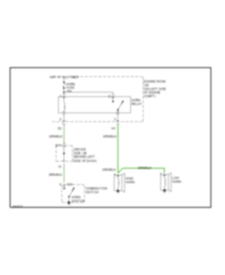
- Horn
- Horn fuse 10a
- Horn relay
- Horns system
- Hot at all times
- Hot in on or start
- Ii (at left kick panel)
- Ij (at left dash brace)
- Junction connector 12 (3.0l, 3.3l, 2.4l except pzev: w/ engine immobilizer system) (left side of dash)
- K10
- K16
- Left front door courtesy switch (lower left "b" pillar)
- Left rear door courtesy switch (lower left "c" pillar)
- Left unlock
- Lgcy
- Lock
- Lsr
- Lswd
- Lswp
- Luggage compartment light switch (center of trunk lid)
- Manual a/c
- Mpx3
- Passenger side j/b (behind right center of dash)
- Pcty
- Rcty
- Right front door courtesy switch (lower right "b" pillar)
- Right front door lock control switch
- Right rear door courtesy switch (lower right "c" pillar)
- Sgnd
- Sig
- Tr+
- Trunk, tailgate fuel doors system
- Ul1
- Ul2
- Ul3
- Unlock
- Unlock warning switch (lower left side of dash)
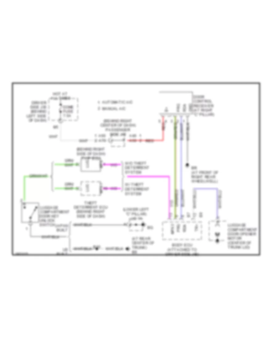
Forced Entry Wiring Diagram (2 of 2) for Toyota Camry LE 2004
List of elements for Forced Entry Wiring Diagram (2 of 2) for Toyota Camry LE 2004:
- (15-23 not used)
- (7-9 not used)
- (behind center of dash) a/c control assembly
- (behind right center of dash) passenger side j/b
- (under driver's seat)
- +b1
- B10
- B14 b34
- B44
- Br (at front of right rear wheelwell)
- Bs (at rear center of trunk)
- Dswh
- Ed (at front of left front fender) (2.4l: left front of engine compt)
- Engine hood courtesy switch (2.4l: on left side of radiator support) (3.0l & 3.3l: at front center of radiator support)
- Gnd
- Ind
- Japan built
- Junction connector 11 (lower left "c" pillar)
- Junction connector 7 & 8 (behind right side of dash)
- Ksw
- Left front door key lock & unlock switch, door lock motor & door unlock detection switch (at left front door)
- Left rear door lock motor & door unlock detection switch (at left rear door)
- Lssr
- Lug
- Luggage compartment door key unlock switch
- Mpx
- Mpx1
- Right front door lock motor, door unlock detection switch, door key lock & unlock switch (at right front door)
- Right rear door lock motor & door unlock detection switch (at right rear door)
- Sh-
- Theft deterrent ecu (behind right side of dash)
- Theft deterrent horn (left rear of engine compt)
- Tvip ecu (behind right side of dash)
- Us built
- W/ theft deterrent module
- W/ tvip
2.4L
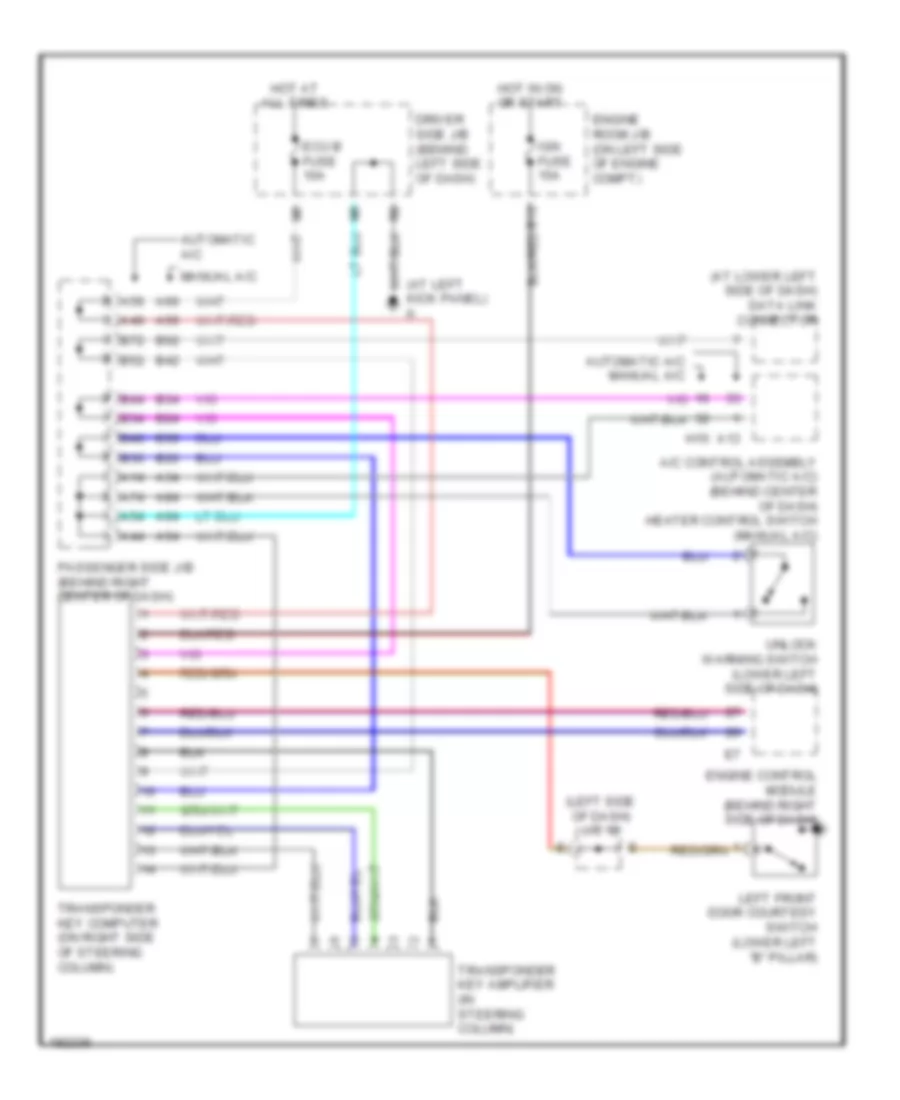
2.4L, Immobilizer Wiring Diagram, PZEV for Toyota Camry LE 2004
List of elements for 2.4L, Immobilizer Wiring Diagram, PZEV for Toyota Camry LE 2004:
- (at left kick panel) ii
- (at lower left side of dash) data link connector
- (left side of dash) j/c 12
- A/c control assembly (automatic a/c) (behind center of dash) heater control switch (manual a/c)
- A13
- A14
- A34
- A44
- A46
- A54
- A56
- A64
- A66
- A74
- A84
- Automatic a/c
- Automatic a/c manual a/c
- B12
- B24
- B26
- B34
- B36
- B42
- B44
- B46
- B52
- B62
- B72
- Driver side j/b (behind left side of dash)
- Ecu b fuse 10a
- Engine control module (behind right side of dash)
- Engine room j/b (on left side of engine compt)
- H10
- Hot at all times
- Hot in on or start
- Ign fuse 15a
- Left front door courtesy switch (lower left "b" pillar)
- Manual a/c
- Passenger side j/b (behind right center of dash)
- Transponder key amplifier (in steering column)
- Transponder key computer (on right side of steering column)
- Unlock warning switch (lower left side of dash)
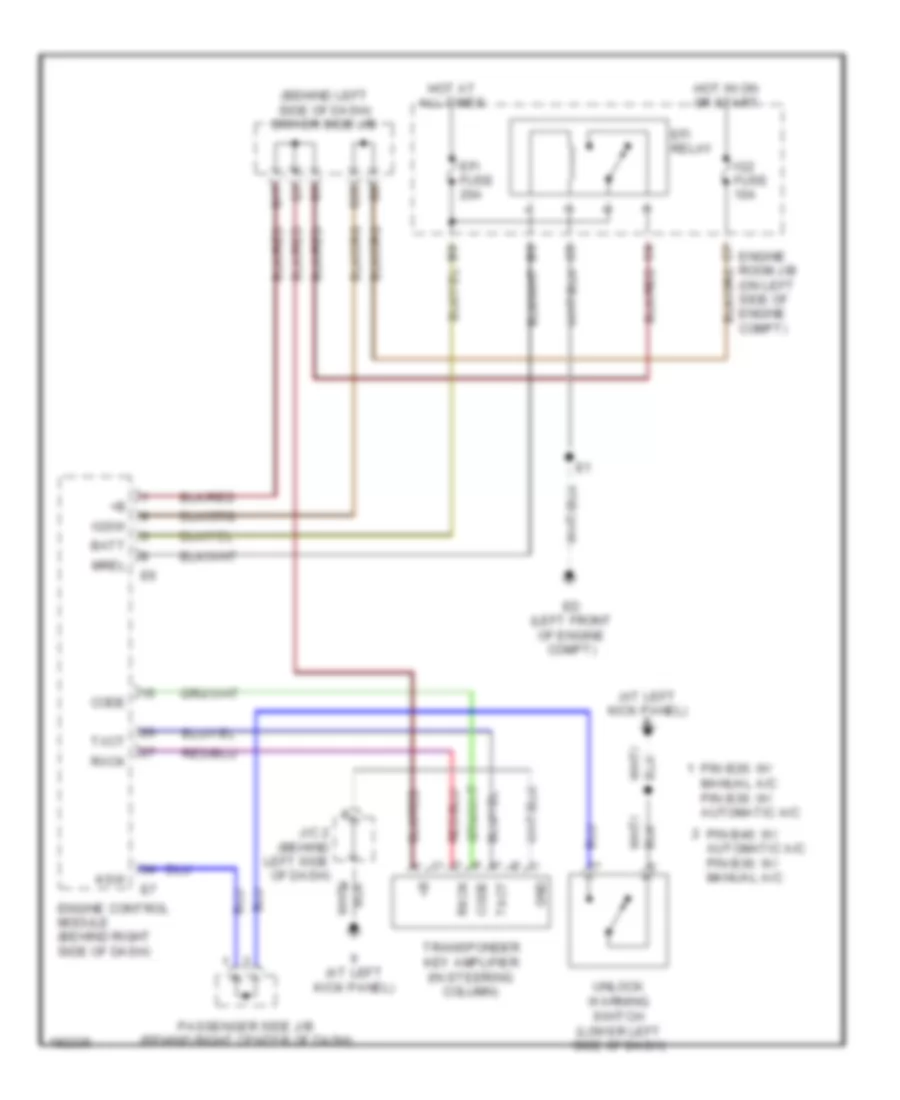
2.4L, Immobilizer Wiring Diagram, Except PZEV for Toyota Camry LE 2004
List of elements for 2.4L, Immobilizer Wiring Diagram, Except PZEV for Toyota Camry LE 2004:
- (at left kick panel) ii
- (behind left side of dash) driver side j/b
- Batt
- Code
- Ed (left front of engine compt)
- Efi fuse 20a
- Efi relay
- Engine control module (behind right side of dash)
- Engine room j/b (on left side of engine compt)
- G17
- G20
- Gnd
- Hot at all times
- Hot in on or start
- Ig2 fuse 10a
- Igsw
- Ii (at left kick panel)
- Ksw
- Mrel
- Passenger side j/b (behind right center of dash)
- Pin b26: w/ manual a/c pin b36: w/ automatic a/c
- Pin b46: w/ automatic a/c pin b36: w/ manual a/c
- Rxck
- Transponder key amplifier (in steering column)
- Txct
- Unlock warning switch (lower left side of dash)
3.0L
3.0L, Immobilizer Wiring Diagram, Except PZEV for Toyota Camry LE 2004
List of elements for 3.0L, Immobilizer Wiring Diagram, Except PZEV for Toyota Camry LE 2004:
- (at left kick panel) ii
- (behind left side of dash) driver side j/b
- Batt
- Code
- Ed (left front of engine compt)
- Efi fuse 20a
- Efi relay
- Engine control module (behind right side of dash)
- Engine room j/b (on left side of engine compt)
- G17
- G20
- Gnd
- Hot at all times
- Hot in on or start
- Ig2 fuse 10a
- Igsw
- Ii (at left kick panel)
- Ksw
- Mrel
- Passenger side j/b (behind right center of dash)
- Pin b26: w/ manual a/c pin b36: w/ automatic a/c
- Pin b46: w/ automatic a/c pin b36: w/ manual a/c
- Rxck
- Transponder key amplifier (in steering column)
- Txct
- Unlock warning switch (lower left side of dash)
3.3L
3.3L, Immobilizer Wiring Diagram, Except PZEV for Toyota Camry LE 2004
List of elements for 3.3L, Immobilizer Wiring Diagram, Except PZEV for Toyota Camry LE 2004:
- (at left kick panel) ii
- (behind left side of dash) driver side j/b
- Batt
- Code
- Ed (left front of engine compt)
- Efi fuse 20a
- Efi relay
- Engine control module (behind right side of dash)
- Engine room j/b (on left side of engine compt)
- G17
- G20
- Gnd
- Hot at all times
- Hot in on or start
- Ig2 fuse 10a
- Igsw
- Ii (at left kick panel)
- Ksw
- Mrel
- Passenger side j/b (behind right center of dash)
- Pin b26: w/ manual a/c pin b36: w/ automatic a/c
- Pin b46: w/ automatic a/c pin b36: w/ manual a/c
- Rxck
- Transponder key amplifier (in steering column)
- Txct
- Unlock warning switch (lower left side of dash)
BODY CONTROL MODULES
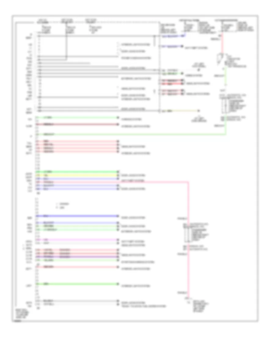
Body Control Modules Wiring Diagram for Toyota Camry LE 2004
List of elements for Body Control Modules Wiring Diagram for Toyota Camry LE 2004:
- (at left kick panel) ii
- (automatic a/c) a110 a120
- (automatic a/c) a80 a90
- (automatic a/c) b41 b31
- (automatic a/c) b71
- (canada)
- (manual a/c)
- (manual a/c) b61
- A/t indicator light switch (on transaxle)
- Acc
- Act+
- Act-
- Actd
- Ajar
- Altl
- Anti-theft system
- Auto
- B11
- Bdr1
- Body ecu (attached to driver side j/b)
- Bzr
- Canada
- Cltb
- Clte
- Clts
- Data link connector 3 (at lower left side of dash)
- Dcty
- Door 1 fuse 25a
- Door locks system
- Driver side j/b (behind left side of dash)
- Drl
- Ecu-acc fuse 5a
- Ecu-b fuse 10a
- Ecu-ig fuse 10a
- Engine room j/b (on left side of engine compartment)
- Exterior lights system
- G11
- G14
- G22
- Gauge 2 fuse 10a
- Gnd
- Haz
- Head
- Headlights system
- Horn
- Horns system
- Hot at all times
- Hot in on or acc
- Hot in on or start
- Hrly
- Ij (at left dash brace)
- Ile
- Interior lights system
- Ksw
- Lgcy
- Lsr
- Lswd
- Lswp
- Mpx3
- Passenger side j/b (behind right center of dash)
- Pcty
- Pkb
- Power windows system
- Prg
- Pws
- Rcty
- Rda
- Red
- Sdrl
- Sgnd
- Sig
- Starting/charging system
- Tail
- Tr+
- Trly
- Trunk, tailgate, fuel doors system
- Ul1
- Ul2
- Ul3
- Usa
- Warning system
COMPUTER DATA LINES
Computer Data Lines Wiring Diagram for Toyota Camry LE 2004
List of elements for Computer Data Lines Wiring Diagram for Toyota Camry LE 2004:
- (2.4l pzev)
- (at lower left side of dash) data link connector 3
- (except 2.4l)
- (w/ power seat)
- (w/o power seat)
- 2.4l pzev
- A23
- Air bag sensor assembly (under front of center floor console)
- Automatic a/c
- B100
- B118
- B32
- B41
- B42
- B52
- B61
- B62
- B70
- B71
- B72
- B78
- B80
- B89
- B91
- B98
- B99
- Bat
- Body ecu (attached to driver side j/b)
- Canh
- Canl
- Combination meter
- D/g
- Dia
- Driver side j/b (behind left side of dash)
- Ef (except 2.4l) (at rear side of surge tank)
- Eg (2.4l) (at left side of cylinder bank)
- Engine control module (behind right side of dash)
- Eom
- Except 2.4l pzev
- G18
- Hot at all times
- I6 i8
- Ii (at left kick panel)
- J/c 13, 14, 15 & 16 (center of dash)
- J13
- J14
- J15
- J16
- Japan built: w/ abs
- Junction connector 1 (behind right side of dash)
- Manual a/c
- Mpx
- Mpx1
- Mpx3
- Obd fuse 7.5a
- Occupant classification ecu (in front passenger's seat)
- Passenger side j/b (behind right center of dash)
- Red
- Sil
- Skid control ecu with actuator (at right side of engine compt)
- Steering sensor (on steering column)
- Tac
- Tach
- Theft deterrent ecu (behind right side of dash)
- Transponder key computer (on right side of steering column)
- Tvip ecu (behind right side of dash)
- Us built: w/ abs
- W/ anti-theft
- W/ vsc
- W/o anti-theft
- Wfse
- Yaw rate sensor (below rear of center floor console)
COOLING FAN
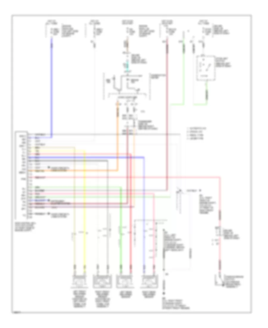
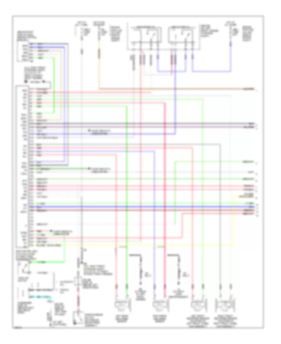
Cooling Fan Wiring Diagram for Toyota Camry LE 2004
List of elements for Cooling Fan Wiring Diagram for Toyota Camry LE 2004:
- (3.0l & 3.3l: on top front of engine)
- (in dash
- 2.4l
- 2.4l pzev
- A/c condenser fan motor (2.4l: at front center of engine compt) (3.0l & 3.3l: on right front of engine compt)
- A/c diode 1 (in front of left front strut tower)
- A/c diode 2 (left side of engine compartment)
- Acmg
- Air conditioning system
- Cds fuse 30a
- Driver side j/b (behind left side of dash)
- E10
- Eb (2.4l: right front of engine compt) (3.0l & 3.3l: at front of right front fender)
- Ec (2.4l: left front of engine compartment) (3.0l & 3.3l: at front of left front fender)
- Ed (2.4l: left front of engine compt) (3.0l & 3.3l: at right side of surge tank)
- Engine control module (behind right side of dash)
- Engine controls system
- Engine coolant temperature sensor (2.4l: on top rear of engine)
- Engine room j/b (on left side of engine compartment)
- Engine room r/b (on left side of engine compartment)
- Except 2.4l
- Except 2.4l pzev
- Fan 1 relay
- Fan 2 relay
- Fan 3 relay
- Fan rly fuse 10a
- H10
- Hot at all times
- Hot in on or start
- K10
- Of dash)
- Pr2
- Pressure switch (2.4l: right front of engine compartment) (3.0l & 3.3l: at right front corner of engine compt)
- Radiator fan motor (2.4l: left front of engine compartment) (3.0l & 3.3l: left front of radiator support)
- Rdi fuse 30a
- Red
- Thw
- Water temperature switch 1 (top center of engine)
- Water temperature switch 2 (left rear of engine)
CRUISE CONTROL
2.4L
2.4L, Cruise Control Wiring Diagram (1 of 2) for Toyota Camry LE 2004
List of elements for 2.4L, Cruise Control Wiring Diagram (1 of 2) for Toyota Camry LE 2004:
- (at left dash brace) ij
- (automatic a/c)
- (behind left side of dash) cruise control clutch switch
- (except pzev)
- (manual a/c)
- (on transaxle)
- (pzev)
- A/t
- A/t indicator light switch
- A101
- A102
- A107
- A109
- A119
- A51
- A57
- A61
- A82
- A89
- A91
- A92
- A99
- B100
- B108
- B110
- B118
- B120
- B128
- B130
- B22
- B32
- B60
- B61
- B62
- B66
- B68
- B70
- B71
- B72
- B76
- B78
- B80
- B81
- B86
- B91
- C10
- Cancel
- Combination meter
- Combination switch
- Cruise
- Cruise control ind
- Cruise control switch
- Data link connector 3 (at lower left side of dash)
- Driver side j/b (behind left side of dash)
- Gauge 1 gauge fuse 10a
- Gauge 2 fuse 10a
- Hot at all times
- Hot in on or start
- Ig+
- Ii (at left kick panel)
- Junction connector 7 & 8 (behind right side of dash) j8
- M/t
- Passenger side j/b (behind right center of dash)
- Pnk
- Resume/ accel
- Set/ coast
- Sil
- Speedometer
- Stop fuse 15a
- Stoplight switch (behind left side of dash)
- Vehicle speed sensor (combination meter) (on transaxle, near rear of engine)
2.4L, Cruise Control Wiring Diagram (2 of 2) for Toyota Camry LE 2004
List of elements for 2.4L, Cruise Control Wiring Diagram (2 of 2) for Toyota Camry LE 2004:
- +bm
- Accelerator position sensor (behind left center of dash)
- Batt
- Ccs
- Driver side j/b (behind left side of dash)
- E01
- E02
- E03
- E04
- E10
- Ed (left front of engine compartment)
- Efi fuse 20a
- Efi relay
- Eg (at left side of cylinder bank)
- Eh (at intake side of cylinder block)
- Engine control module (behind right side of dash)
- Engine room j/b (on left side of engine compartment)
- Ep1
- Ep2
- Epa
- Epa2
- Etcs fuse 10a
- Except pzev
- G17
- G20
- Ge01
- Hot at all times
- Hot in on or start
- Ig 2 fuse 10a
- Igsw
- Junction connector 1 (behind right side of dash)
- Me01
- Mrel
- Nca
- Pzev
- Red
- Sil
- Spd
- St1-
- Stp
- Throttle position sensor
- Vcp1
- Vcp2
- Vcpa
- Vpa
- Vpa1
- Vpa2
- Vta
- Vta2
3.0L
3.0L, Cruise Control Wiring Diagram (1 of 2) for Toyota Camry LE 2004
List of elements for 3.0L, Cruise Control Wiring Diagram (1 of 2) for Toyota Camry LE 2004:
- (automatic a/c)
- (automatic a/c) (manual a/c)
- (manual a/c)
- A/t indicator light switch (on transaxle)
- A101
- A102
- A109
- A119
- A51
- A61
- A82
- A91
- A92
- A99
- B100
- B108
- B110
- B118
- B120
- B128
- B130
- B22
- B32
- B60
- B61
- B62
- B64
- B68
- B70
- B71
- B72
- B74
- B76 b66
- B78
- B80
- B81
- B84
- B86 b76
- B91
- C10
- Cancel
- Combination meter
- Combination switch
- Cruise
- Cruise control ind
- Cruise control switch
- Data link connector 3 (at lower left side of dash)
- Driver side j/b (behind left side of dash)
- Gauge 2 fuse 10a
- Hot at all times
- Hot in on or start
- Ii (at left kick panel)
- Ij (at left dash brace)
- Japan built
- Passenger side j/b (behind right center of dash)
- Resume/ accel
- Set/ coast
- Sil
- Skid control ecu w/ actuator (at right side of engine compartment)
- Skid control ecu w/ actuator (at right side of engine compt)
- Sp1
- Speedometer
- Stop fuse 15a
- Stoplight switch (behind left side of dash)
- Us built
- W/ vsc
- W/o vsc
3.0L, Cruise Control Wiring Diagram (2 of 2) for Toyota Camry LE 2004
List of elements for 3.0L, Cruise Control Wiring Diagram (2 of 2) for Toyota Camry LE 2004:
- (center of dash) i10
- +b2
- +bm
- Accelerator position sensor (behind left center of dash)
- Batt
- Ccs
- Driver side j/b (behind left side of dash)
- E01
- E02
- E03
- E05
- E10
- Ed (at front of left front fender)
- Ee (at right side of surge tank)
- Ef (at rear side of surge tank)
- Efi fuse 20a
- Efi relay
- Engine control module (behind right side of dash)
- Engine room j/b (on left side of engine compartment)
- Eo4
- Ep1
- Ep2
- Epa
- Epa2
- Etcs fuse 10a
- G17
- G20
- Ge01
- Hot at all times
- Hot in on or start
- Ig2 fuse 10a
- Igsw
- Junction connector 1 (behind right side of dash)
- Me01
- Mrel
- Nca
- Red
- Sil
- Spd
- St1-
- Stp
- Throttle position sensor (on throttle body)
- Vcp2
- Vcpa
- Vpa
- Vpa1
- Vpa2
- Vta1
- Vta2
3.3L
3.3L, Cruise Control Wiring Diagram (1 of 2) for Toyota Camry LE 2004
List of elements for 3.3L, Cruise Control Wiring Diagram (1 of 2) for Toyota Camry LE 2004:
- (automatic a/c)
- (automatic a/c) (manual a/c)
- (manual a/c)
- A/t indicator light switch (on transaxle)
- A101
- A102
- A109
- A119
- A51
- A61
- A82
- A91
- A92
- A99
- B100
- B108
- B110
- B118
- B120
- B128
- B130
- B22
- B32
- B60
- B61
- B62
- B64
- B68
- B70
- B71
- B72
- B74
- B76 b66
- B78
- B80
- B81
- B84
- B86 b76
- B91
- C10
- Cancel
- Combination meter
- Combination switch
- Cruise
- Cruise control ind
- Cruise control switch
- Data link connector 3 (at lower left side of dash)
- Driver side j/b (behind left side of dash)
- Gauge 2 fuse 10a
- Hot at all times
- Hot in on or start
- Ii (at left kick panel)
- Ij (at left dash brace)
- Japan built
- Passenger side j/b (behind right center of dash)
- Resume/ accel
- Set/ coast
- Sil
- Skid control ecu w/ actuator (at right side of engine compartment)
- Skid control ecu w/ actuator (at right side of engine compt)
- Sp1
- Speedometer
- Stop fuse 15a
- Stoplight switch (behind left side of dash)
- Us built
- W/ vsc
- W/o vsc
3.3L, Cruise Control Wiring Diagram (2 of 2) for Toyota Camry LE 2004
List of elements for 3.3L, Cruise Control Wiring Diagram (2 of 2) for Toyota Camry LE 2004:
- (center of dash) i10
- +b2
- +bm
- Accelerator position sensor (behind left center of dash)
- Batt
- Ccs
- Driver side j/b (behind left side of dash)
- E01
- E02
- E03
- E05
- E10
- Ed (at front of left front fender)
- Ee (at right side of surge tank)
- Ef (at rear side of surge tank)
- Efi fuse 20a
- Efi relay
- Engine control module (behind right side of dash)
- Engine room j/b (on left side of engine compartment)
- Eo4
- Ep1
- Ep2
- Epa
- Epa2
- Etcs fuse 10a
- G17
- G20
- Ge01
- Hot at all times
- Hot in on or start
- Ig2 fuse 10a
- Igsw
- Junction connector 1 (behind right side of dash)
- Me01
- Mrel
- Nca
- Red
- Sil
- Spd
- St1-
- Stp
- Throttle position sensor (on throttle body)
- Vcp2
- Vcpa
- Vpa
- Vpa1
- Vpa2
- Vta1
- Vta2
DEFOGGERS
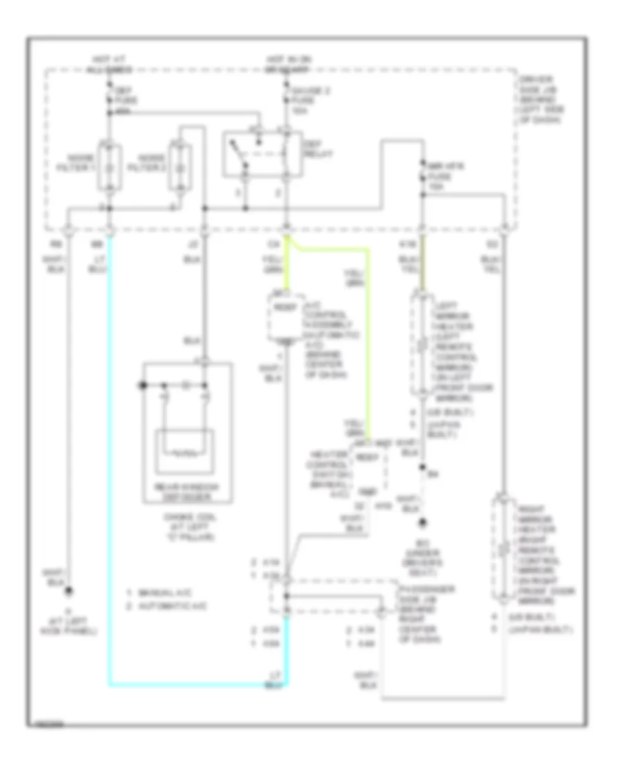
Defoggers Wiring Diagram for Toyota Camry LE 2004
List of elements for Defoggers Wiring Diagram for Toyota Camry LE 2004:
- (japan built)
- (us built)
- A/c control assembly (automatic a/c) (behind center of dash)
- A14
- A34
- A44
- A54
- A64
- Automatic a/c
- Bo (under driver's seat)
- Choke coil (at left "c" pillar)
- Def fuse 40a
- Def relay
- Driver side j/b (behind left side of dash)
- Gauge 2 fuse 10a
- Gnd
- H10
- Heater control switch (manual a/c)
- Hot at all times
- Hot in on or start
- Ii (at left kick panel)
- K18
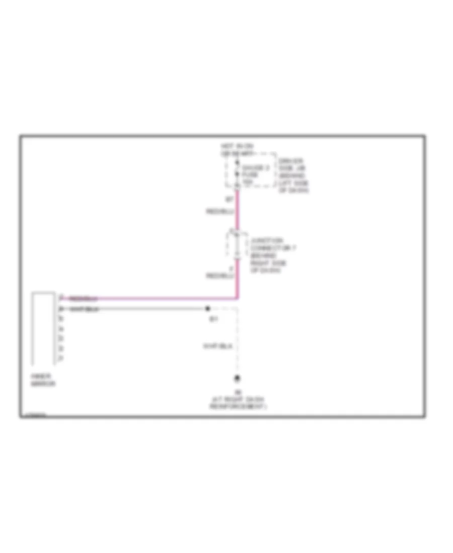
- Left mirror heater (left remote control mirror) (in left front door mirror)
- Manual a/c
- Mir htr fuse 10a
- Noise filter 1
- Noise filter 2
- Passenger side j/b (behind right center of dash)
- Rdef
- Rear window defogger
- Right mirror heater (right remote control mirror) (in right front door mirror)
ENGINE PERFORMANCE
2.4L
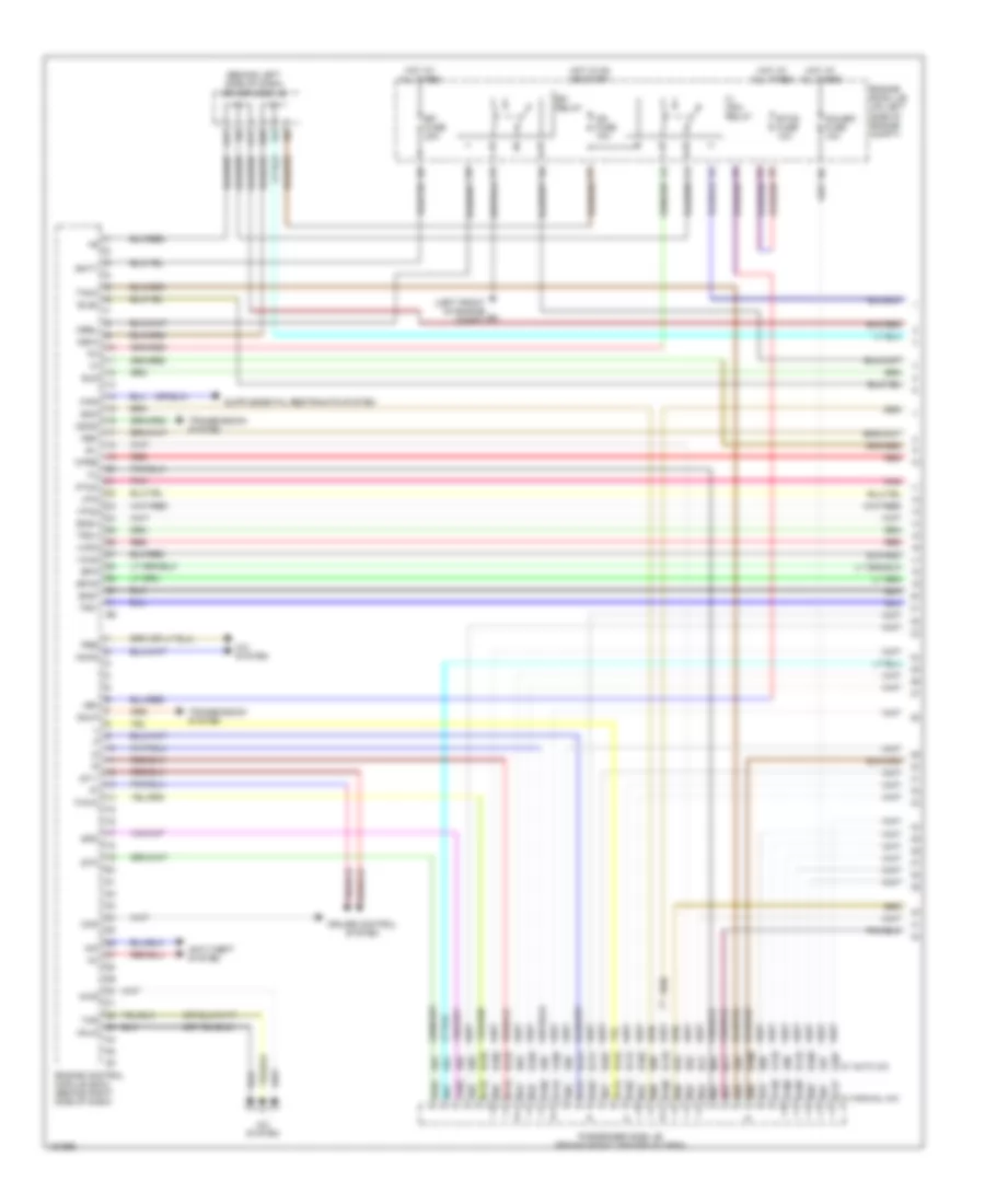
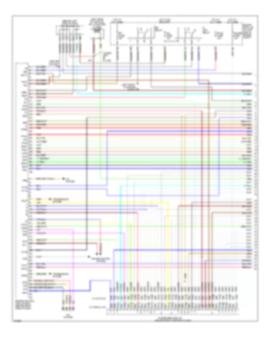
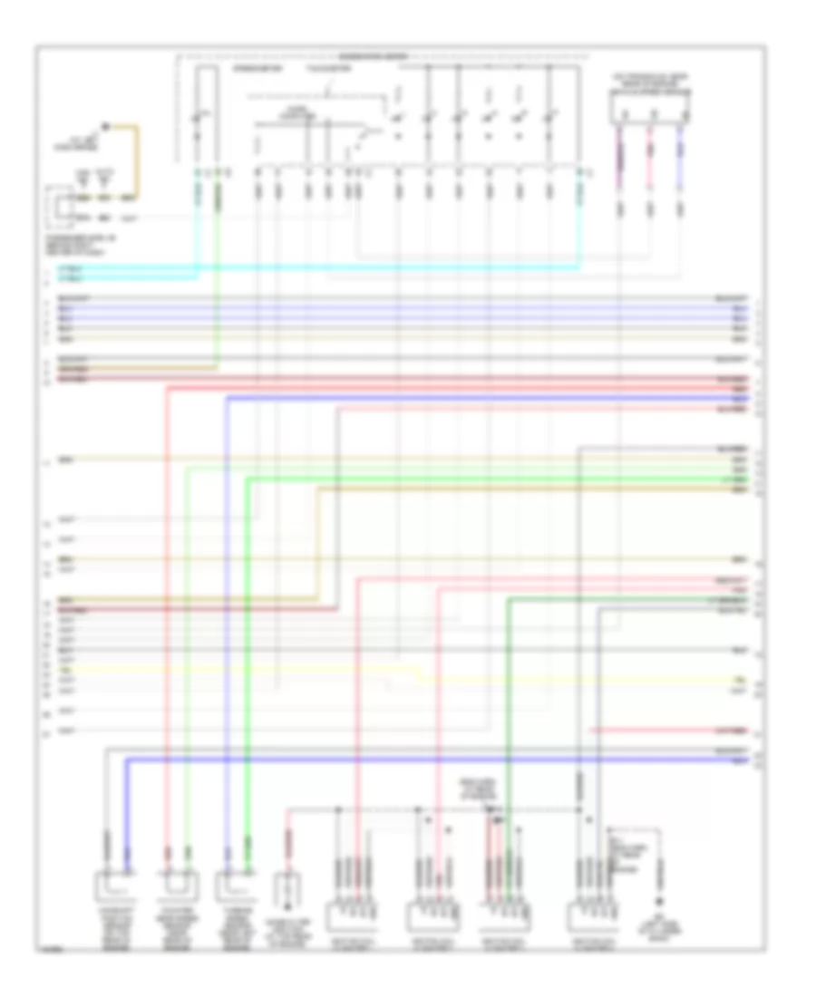
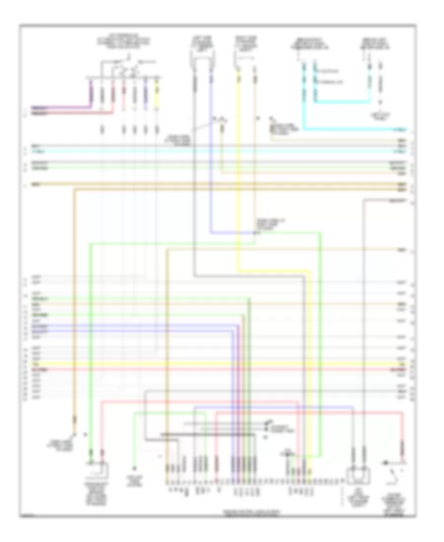
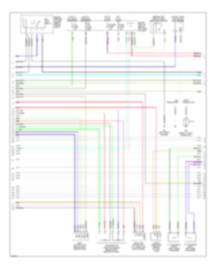
2.4L, Engine Performance Wiring Diagram, Except PZEV (1 of 6) for Toyota Camry LE 2004
List of elements for 2.4L, Engine Performance Wiring Diagram, Except PZEV (1 of 6) for Toyota Camry LE 2004:
- (behind left side of dash) driver side j/b
- (left front of engine compt)
- +bm
- A/c system
- A/cs
- A100
- A101
- A102
- A105
- A107
- A110
- A115
- A117
- A120
- A51
- A57
- A61
- A67
- A82
- A85
- A90
- A91
- A92
- A95
- Acld
- Acmg
- Anti-theft system
- B100
- B101
- B102
- B103
- B105
- B108
- B109
- B111
- B112
- B113
- B115
- B118
- B119
- B121
- B122
- B123
- B125
- B53
- B61
- B62
- B63
- B68
- B71
- B72
- B78
- B79
- B81
- B82
- B88
- B89
- B90
- B91
- B92
- B93
- B95
- B98
- B99
- Batt
- C/ opn relay
- Ccs
- Cruise control system
- Efi fuse 20a
- Efi relay
- Els
- Els2
- Eng+
- Eng-
- Engine control module (ecm) (behind right side of dash)
- Engine room j/b (on left side of engine compt)
- Eom
- Epa
- Epa2
- Etcs fuse 10a
- F/ps
- G17
- G20
- Gauge1 fuse 10a
- Hot at all times
- Hot in on or start
- Ig2 fuse 10a
- Igsw
- Imi
- Imo
- K17
- Mrel
- Neo
- Odlp
- Odms
- Passenger side j/b (behind right center of dash)
- Pnk
- Pre
- Ptnk
- Red
- Sil
- Spd
- St1-
- Stp
- Tach
- Thr
- Thwo
- Transmission system
- Trc+
- Trc-
- Vca2
- Vcp2
- Vpa
- Vpa2
- W/ auto a/c
- W/ manual a/c
- Wfse
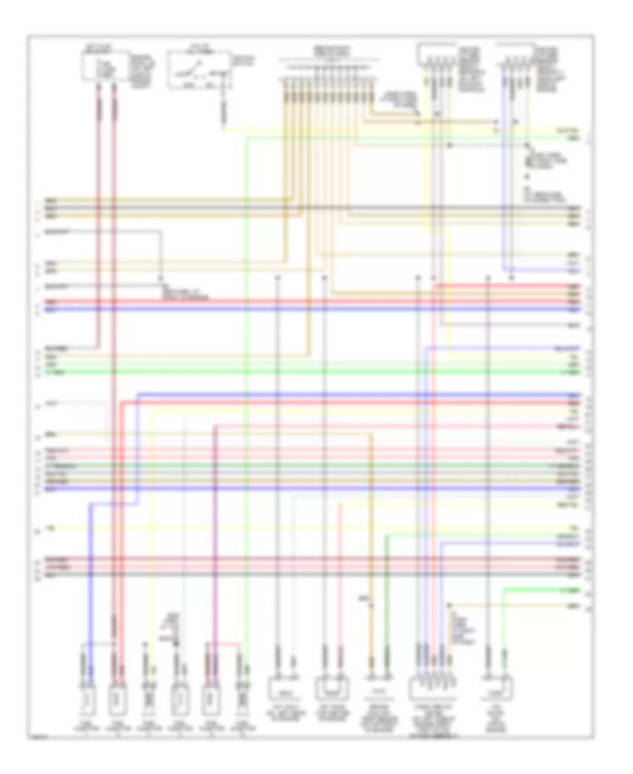
2.4L, Engine Performance Wiring Diagram, Except PZEV (2 of 6) for Toyota Camry LE 2004
List of elements for 2.4L, Engine Performance Wiring Diagram, Except PZEV (2 of 6) for Toyota Camry LE 2004:
- (behind left side of dash) stoplight switch
- (in fuel tank) fuel pump & fuel sender
- Accelerator position sensor (behind left center of dash)
- Bq (front of left wheelwell)
- Data link connector 3 (at lower left side of dash)
- Driver side j/b (behind left side of dash)
- Eng+
- Eng-
- G13
- G16
- Gauge2 fuse 10a
- Hot at all times
- Hot in on or start
- Hot w/ def relay energized
- Hot w/ tail relay energized
- J/c 12
- Japan production
- Mir htr fuse 10a
- Neo
- Pnk
- Ptnk
- Red
- Sil
- Skid control ecu (behind right side of dash)
- Stop fuse 15a
- Tac
- Tail fuse 10a
- Trc+
- Trc-
- Usa production
- Vapor pressure sensor (at fuel tank)
- Vcc
- Wfse
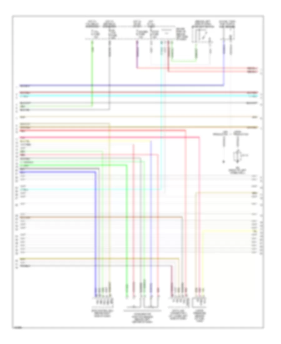
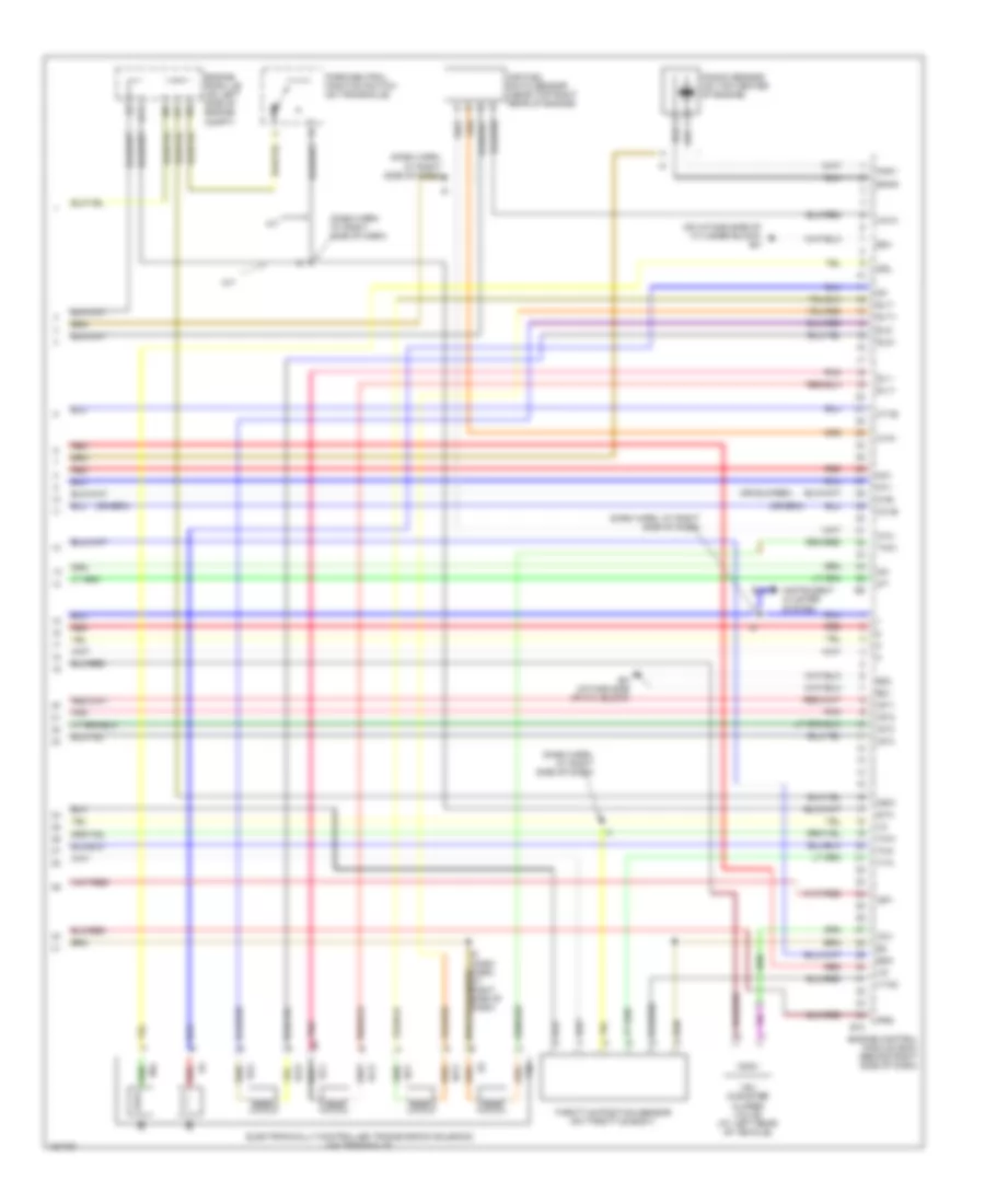
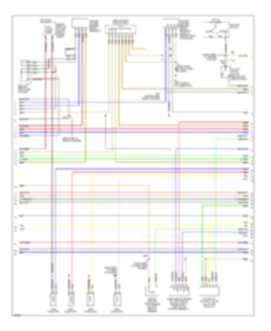
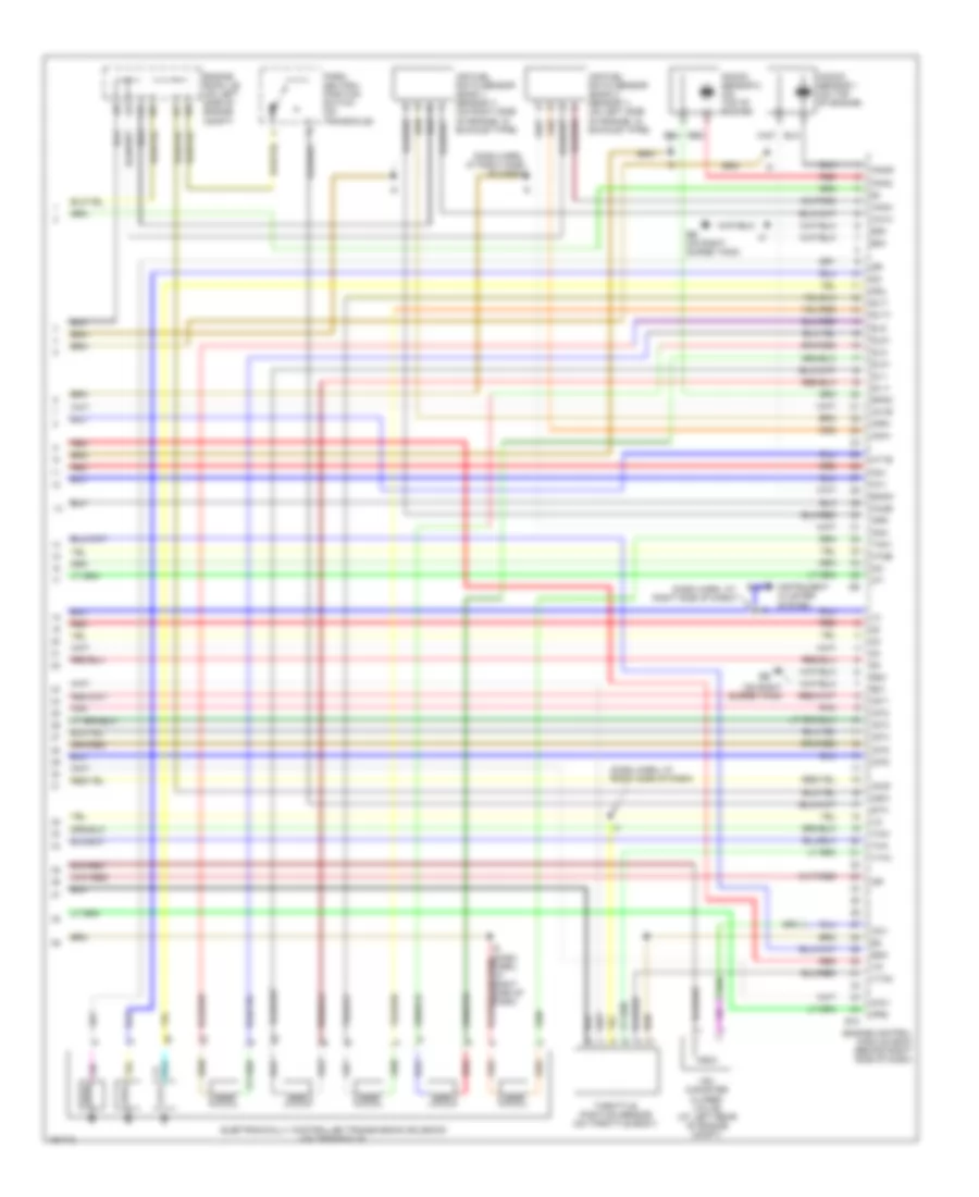
2.4L, Engine Performance Wiring Diagram, Except PZEV (3 of 6) for Toyota Camry LE 2004
List of elements for 2.4L, Engine Performance Wiring Diagram, Except PZEV (3 of 6) for Toyota Camry LE 2004:
- (behind left side of dash) driver side j/b
- (behind right center of dash) passenger side j/b
- (dash harn, at right side of dash)
- (dash harn, at right side of dash) i6
- (intake side of cylinder block)
- (left front of engine) crankshaft position sensor
- (left side of cylinder bank)
- (on transaxle) a/t indicator light switch (integral to park/neutral position switch)
- (or red)
- (top rear of engine) camshaft position sensor
- A/c system
- A54
- A64
- A84
- A94
- Braided
- Cooling fans system
- E03
- Engine control module (ecm) (behind right side of dash)
- Ge01
- Ii (left kick panel)
- Lcki
- Me01
- Ne+
- Ne-
- Ocv+
- Ocv-
- Power steering oil pressure switch (near front of engine)
- Pr2
- Red
- Vvt solenoid (near front of engine)
- W/ auto a/c
- W/ manual a/c
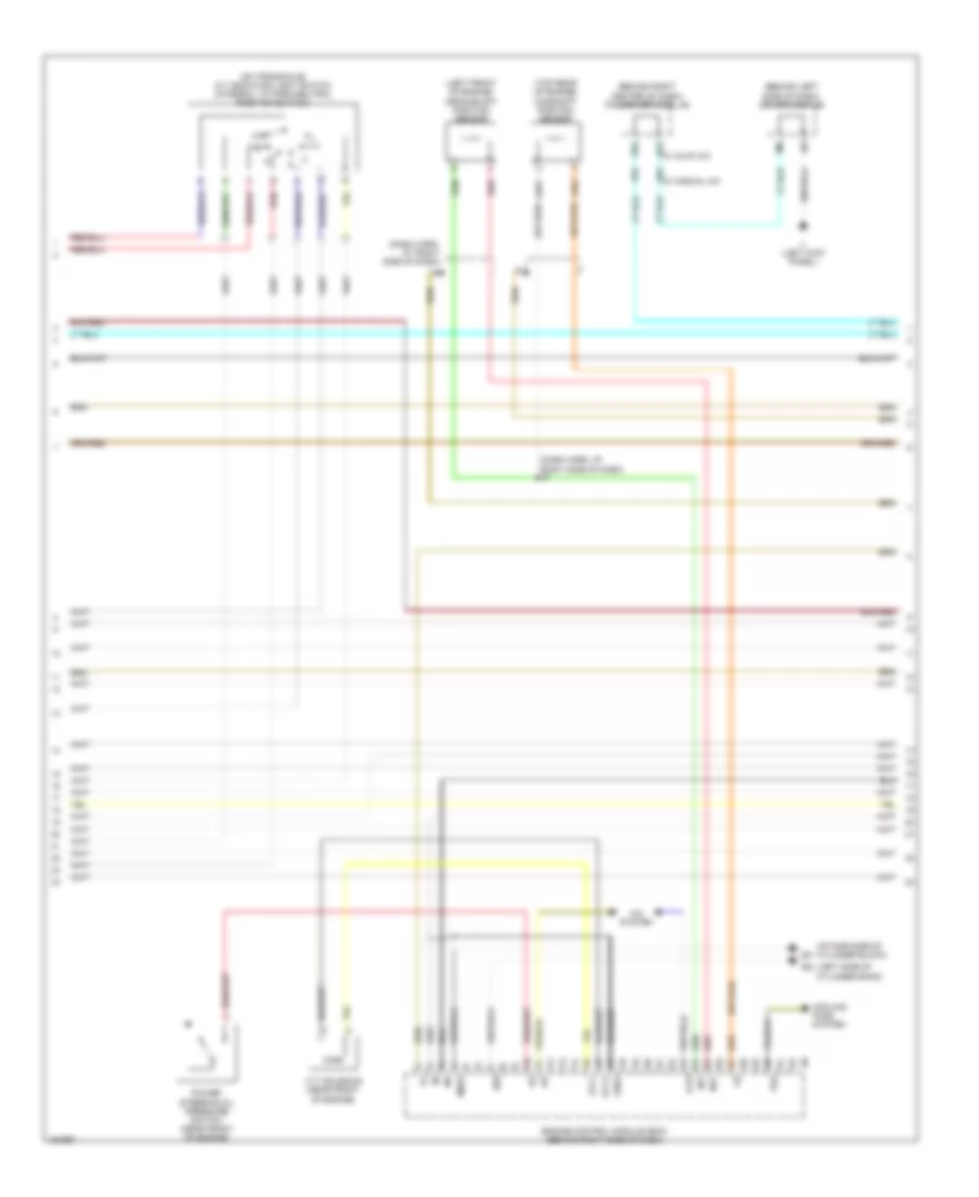
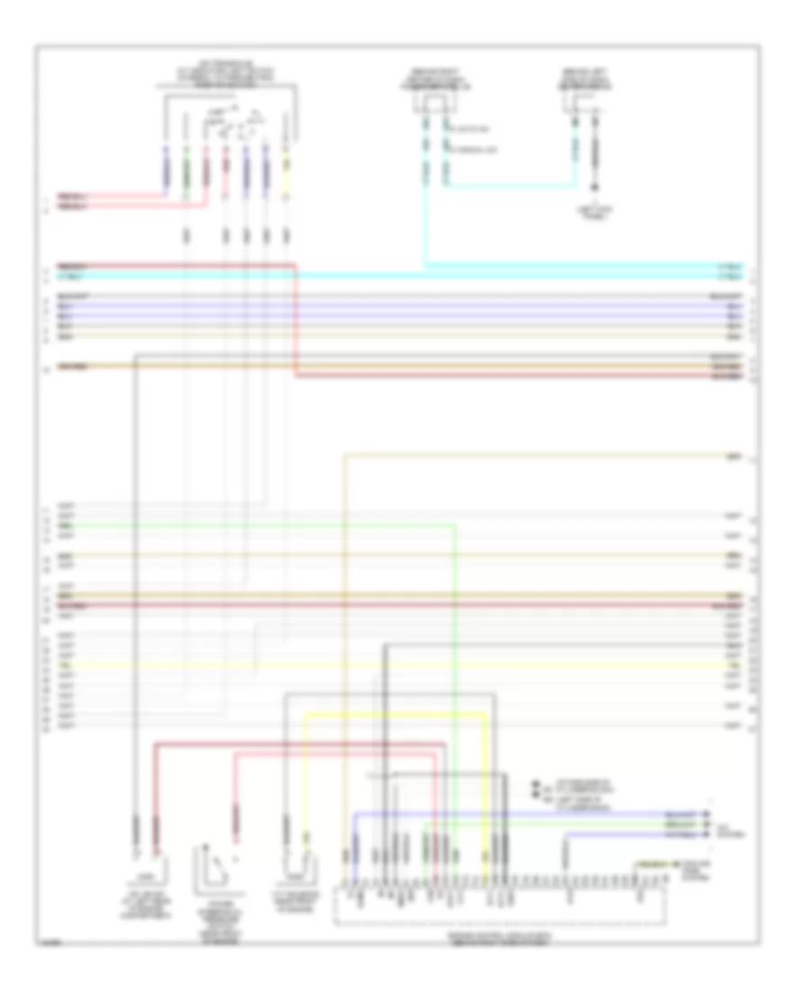
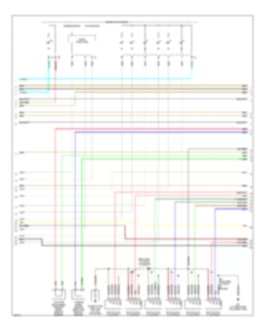
2.4L, Engine Performance Wiring Diagram, Except PZEV (4 of 6) for Toyota Camry LE 2004
List of elements for 2.4L, Engine Performance Wiring Diagram, Except PZEV (4 of 6) for Toyota Camry LE 2004:
- (eng harn, at rear of engine)
- (on transaxle, near rear of engine) vehicle speed sensor
- Auto a/c
- B66
- B76
- B86
- Combination meter
- Counter gear speed sensor (near rear of engine)
- E11 (eng harn, at rear of engine)
- E12
- Eg (left side of cylinder bank)
- Gnd
- Ig+
- Igf
- Ignition coil & igniter 1
- Ignition coil & igniter 2
- Ignition coil & igniter 3
- Ignition coil & igniter 4
- Igt
- Ij (on left dash brace)
- Man a/c
- Micro computer
- Mil
- Noise filter (ignition) (at top rear of engine)
- Passenger side j/b (behind right center of dash)
- Pnk
- Red
- Speedometer
- Tachometer
- Turbine speed sensor (near left rear of engine)
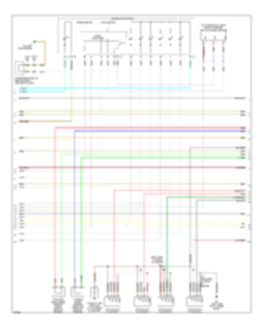
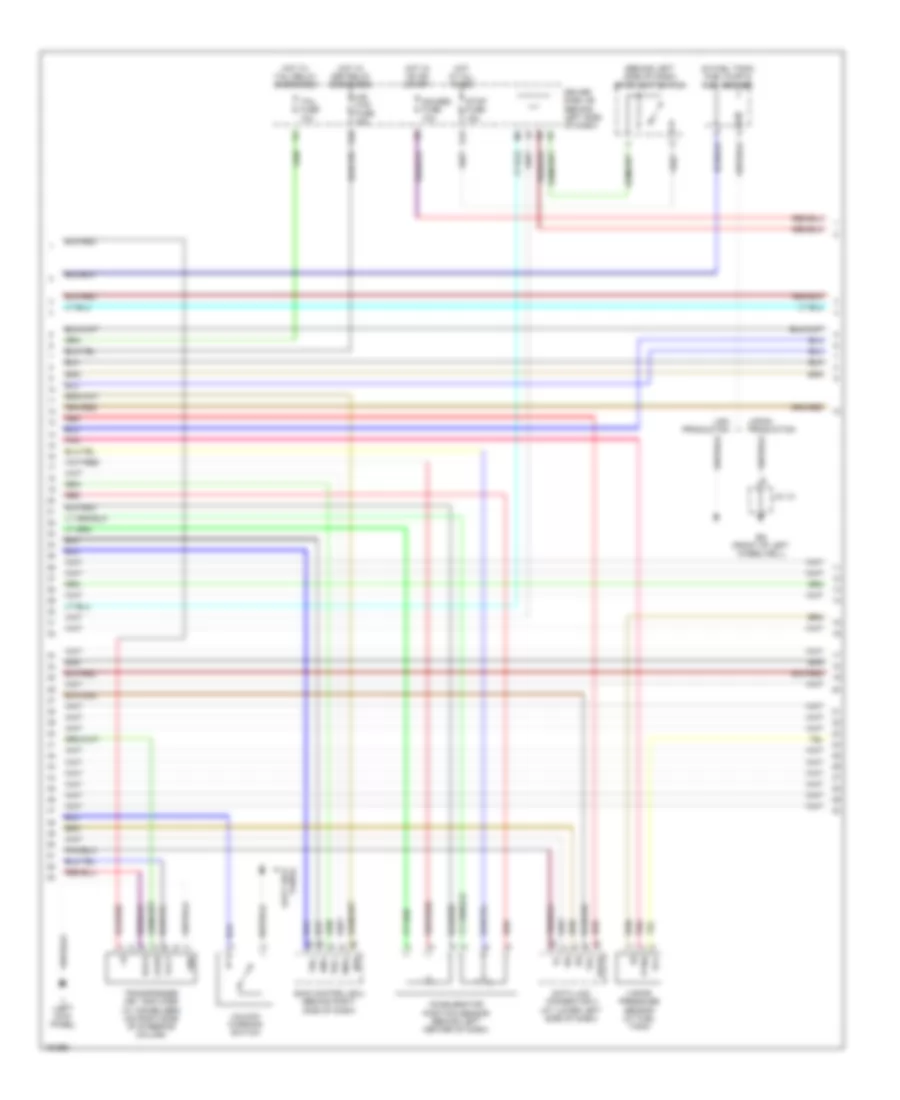
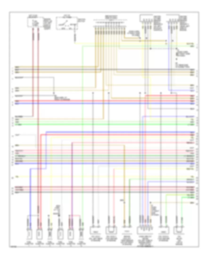
2.4L, Engine Performance Wiring Diagram, Except PZEV (5 of 6) for Toyota Camry LE 2004
List of elements for 2.4L, Engine Performance Wiring Diagram, Except PZEV (5 of 6) for Toyota Camry LE 2004:
- (behind right side of dash) j/c 1
- (dash harn, at center of dash)
- (dash harn, at right side of dash)
- A/t
- Acc
- Clutch start switch (behind left side of dash)
- E2g
- E8 (rear of cylinder head)
- Eg (left side of cyl bank)
- Engine coolant temp sensor (on top rear of engine)
- Engine room j/b (on left side of engine compt)
- Fuel injector 1
- Fuel injector 2
- Fuel injector 3
- Fuel injector 4
- Heated oxygen sensor (bank 1 sensor 1) (rear of engine compt, in exhaust)
- Hot at all times
- Hot in on or start
- I6 (dash harn, at right side of dash)
- Ign fuse 15a
- Ignition switch
- L10
- Lock
- M/t
- Mass airflow meter (on left side of engine compt, part of air intake assembly)
- Pnk
- Red
- Start
- Tha
- Vsv (evap) (at left rear of engine compartment)
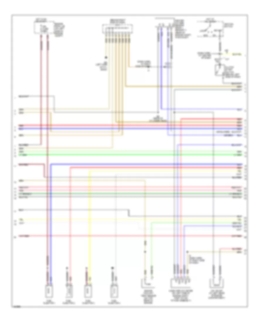
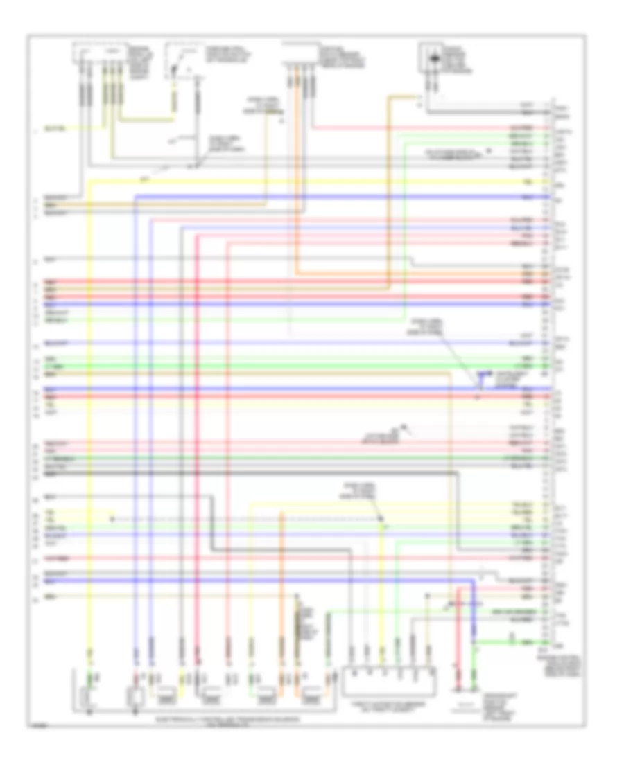
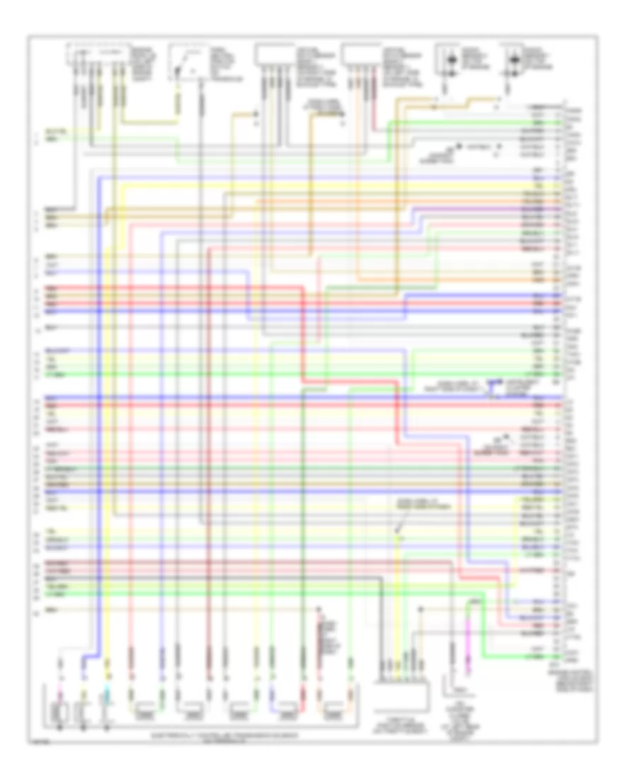
2.4L, Engine Performance Wiring Diagram, Except PZEV (6 of 6) for Toyota Camry LE 2004
List of elements for 2.4L, Engine Performance Wiring Diagram, Except PZEV (6 of 6) for Toyota Camry LE 2004:
- (dash harn, at right side of dash)
- (on intake side of cylinder block) eh
- A/t
- A1a+
- A1a-
- Air fuel ratio sensor (near top right rear of engine)
- Ccv
- Dsl
- E01
- E02
- E04
- E10
- E2g
- Eh (intake side of cyl block)
- Eknk
- Electronically controlled transmission solenoid (on transaxle)
- Engine control module (ecm) (behind right side of dash)
- Engine room j/b (on left side of engine compt)
- Ha1a
- Ht1b
- I6 (dash harn, at right side of dash)
- Igf1
- Igt1
- Igt2
- Igt3
- Igt4
- Instrument cluster system
- K11
- Knk1
- Knock sensor (on top center of engine)
- M/t
- Nc+
- Nc-
- Nsw
- Nt+
- Nt-
- O1b-
- Ox1b
- P/n
- Park/neutral position switch (0n transaxle)
- Pnk
- Prg
- Red
- Sl1+
- Sl1-
- Sl2+
- Sl2-
- Slt+
- Slt-
- Sta
- Tha
- Tho
- Tho1
- Throttle position sensor (on throttle body)
- Thw
- Vsv (canister closed valve) (at left rear of vehicle)
- Vta
- Vta2
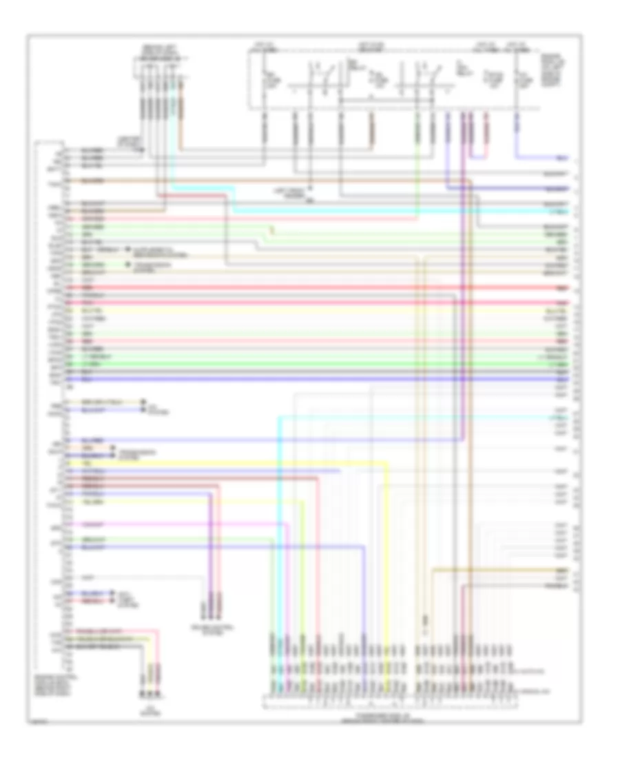
2.4L, Engine Performance Wiring Diagram, PZEV (1 of 6) for Toyota Camry LE 2004
List of elements for 2.4L, Engine Performance Wiring Diagram, PZEV (1 of 6) for Toyota Camry LE 2004:
- (behind left side of dash) driver side j/b
- (behind right center of dash)
- (center of dash) i10
- (left front of engine compt)
- (left rear of vehicle) vsv (canister closed valve)
- (lower left "b" pillar)
- +b1
- +bm
- A/c system
- A/ci
- A/cs
- A100
- A101
- A102
- A105
- A107
- A110
- A115
- A117
- A120
- A51
- A57
- A61
- A67
- A82
- A85
- A90
- A91
- A92
- A95
- B100
- B101
- B102
- B103
- B105
- B108
- B109
- B111
- B112
- B113
- B115
- B117
- B118
- B119
- B121
- B122
- B123
- B125
- B127
- B17
- B22
- B26
- B32
- B36
- B46
- B53
- B61
- B62
- B63
- B68
- B69
- B71
- B72
- B78
- B79
- B81
- B88
- B89
- B90
- B91
- B92
- B93
- B95
- B98
- B99
- Batt
- C/ opn relay
- Ccs
- Code
- Cruise control system
- Efi fuse 20a
- Efi relay
- Els
- Els2
- Eng+
- Eng-
- Engine control module (ecm) (behind right side of dash)
- Engine room j/b (on left side of engine compt)
- Eom
- Epa
- Epa2
- Etcs fuse 10a
- G17
- G20
- Gauge1 fuse 10a
- Hot at all times
- Hot in on or start
- Ht1b
- Ht1c
- Ig2 fuse 10a
- Igsw
- Imld
- K17
- Ksw
- Mrel
- Neo
- Odlp
- Odms
- Ox1b
- Passenger side j/b
- Pnk
- Pre
- Ptnk
- Red
- Rxck
- Sil
- Spd
- St1-
- Stp
- Tach
- Thr
- Thwo
- Transmission system
- Trc+
- Trc-
- Txct
- Vca2
- Vcp2
- Vpa
- Vpa2
- W/ auto a/c
- W/ manual a/c
- Wfse
2.4L, Engine Performance Wiring Diagram, PZEV (2 of 6) for Toyota Camry LE 2004
List of elements for 2.4L, Engine Performance Wiring Diagram, PZEV (2 of 6) for Toyota Camry LE 2004:
- (behind left side of dash) stoplight switch
- (in fuel tank) fuel pump & fuel sender
- (left kick panel)
- Accelerator position sensor (behind left center of dash)
- Bq (front of left wheelwell)
- Code
- Data link connector 3 (at lower left side of dash)
- Driver side j/b (behind left side of dash)
- Eng+
- Eng-
- G13
- G16
- Gauge2 fuse 10a
- Gnd
- Hot at all times
- Hot in on or start
- Hot w/ def relay energized
- Hot w/ tail relay energized
- Ii (left kick panel)
- J/c 12
- Japan production
- Mir htr fuse 10a
- Neo
- Pnk
- Ptnk
- Red
- Rxck
- Sil
- Skid control ecu (behind right side of dash)
- Stop fuse 15a
- Tac
- Tail fuse 10a
- Transponder key amplifier (w/ immobilizer) (on right side of steering column)
- Trc+
- Trc-
- Txct
- Unlock warning switch
- Usa production
- Vapor pressure sensor (at fuel tank)
- Vcc
- Wfse
2.4L, Engine Performance Wiring Diagram, PZEV (3 of 6) for Toyota Camry LE 2004
List of elements for 2.4L, Engine Performance Wiring Diagram, PZEV (3 of 6) for Toyota Camry LE 2004:
- (behind left side of dash) driver side j/b
- (behind right center of dash) passenger side j/b
- (intake side of cylinder block)
- (left side of cylinder bank)
- (on transaxle) a/t indicator light switch (integral to park/neutral position switch)
- A/c system
- A54
- A64
- A84
- A94
- Acmg
- Braided
- Ccv
- Cooling fans system
- E03
- Engine control module (ecm) (behind right side of dash)
- Evp1
- Fan
- Ge01
- Ii (left kick panel)
- Lcki
- Me01
- Ocv+
- Ocv-
- Power steering oil pressure switch (near front of engine)
- Pr2
- Red
- Vsv (evap) (at left rear of engine compartment)
- Vvt solenoid (near front of engine)
- W/ auto a/c
- W/ manual a/c
2.4L, Engine Performance Wiring Diagram, PZEV (4 of 6) for Toyota Camry LE 2004
List of elements for 2.4L, Engine Performance Wiring Diagram, PZEV (4 of 6) for Toyota Camry LE 2004:
- (eng harn, at rear of engine)
- (on transaxle, near rear of engine) vehicle speed sensor
- Auto a/c
- B66
- B76
- B86
- Camshaft position sensor (on top rear of engine)
- Combination meter
- Counter gear speed sensor (near rear of engine)
- E11 (eng harn, at rear of engine)
- E12
- E15
- Eg (left side of cylinder bank)
- Gnd
- Ig+
- Igf
- Ignition coil & igniter 1
- Ignition coil & igniter 2
- Ignition coil & igniter 3
- Ignition coil & igniter 4
- Igt
- Ij (at left dash brace)
- Man a/c
- Micro computer
- Mil
- Noise filter (ignition) (at top rear of engine)
- Passenger side j/b (behind right center of dash)
- Pnk
- Red
- Speedometer
- Tachometer
- Turbine speed sensor (near left rear of engine)
2.4L, Engine Performance Wiring Diagram, PZEV (5 of 6) for Toyota Camry LE 2004
List of elements for 2.4L, Engine Performance Wiring Diagram, PZEV (5 of 6) for Toyota Camry LE 2004:
- (behind right side of dash) j/c 1
- (dash harn, at center of dash)
- (eng harn, at rear of engine)
- (engine harn, rear of engine)
- A/t
- Acc
- Clutch start switch (behind left side of dash)
- E12
- E13
- E14
- E2g
- Eg (left side of cylinder bank)
- Engine coolant temp sensor (on top rear of engine)
- Engine room j/b (on left side of engine compt)
- Fuel injector 1
- Fuel injector 2
- Fuel injector 3
- Fuel injector 4
- Heated oxygen sensor (bank 1 sensor 1) (rear of engine compt, in exhaust)
- Heated oxygen sensor (bank 1 sensor 2)
- Hot at all times
- Hot in on or start
- I6 (dash harn, at right side of dash)
- Ign fuse 15a
- Ignition switch
- Intake air control valve (on intake manifold)
- J/c 7, j/c 8 (behind right side of dash)
- L10
- Lock
- M/t
- Mass airflow meter (on left side of engine compt, part of air intake assembly)
- Nca
- Pnk
- Red
- Start
- Tha
2.4L, Engine Performance Wiring Diagram, PZEV (6 of 6) for Toyota Camry LE 2004
List of elements for 2.4L, Engine Performance Wiring Diagram, PZEV (6 of 6) for Toyota Camry LE 2004:
- (dash harn, at right side of dash)
- (on intake side of cylinder block)
- A/t
- Af1a+
- Af1a-
- Air fuel ratio sensor (near top right rear of engine)
- Crankshaft position sensor (left front of engine)
- Dsl
- E01
- E02
- E04
- E10
- E2g
- Eh (intake side of cyl block)
- Eknk
- Electronically controlled transmission solenoid (on transaxle)
- Engine control module (ecm) (behind right side of dash)
- Engine room j/b (on left side of engine compt)
- G22+
- Haf1a
- I6 (dash harn, at right side of dash)
- Iac+
- Iac-
- Iaca
- Igf
- Igt1
- Igt2
- Igt3
- Igt4
- Instrument cluster system
- K11
- Knk1
- Knock sensor (on top center of engine)
- M/t
- Nc+
- Nc-
- Ne+
- Ne-
- Nsw
- Nt+
- Nt-
- Ox1b
- P/n
- Park/neutral position switch (0n transaxle)
- Pnk
- Red
- Sl1+
- Sl1-
- Sl2+
- Sl2-
- Slt+
- Slt-
- Sta
- Tha
- Tho
- Throttle position sensor (on throttle body)
- Thw
- Vta
- Vta2
3.0L
3.0L, Engine Performance Wiring Diagram (1 of 6) for Toyota Camry LE 2004
List of elements for 3.0L, Engine Performance Wiring Diagram (1 of 6) for Toyota Camry LE 2004:
- (behind left side of dash) driver side j/b
- (center of dash) i10
- (left front fender)
- +b2
- +bm
- A/c system
- A/ci
- A/cs
- A/f fuse 25a
- A100
- A101
- A102
- A105
- A110
- A115
- A120
- A51
- A61
- A82
- A85
- A90
- A91
- A92
- A95
- Acmg
- Anti- theft system
- B101
- B102
- B103
- B105
- B108
- B109
- B111
- B112
- B113
- B115
- B118
- B119
- B121
- B122
- B123
- B125
- B22
- B32
- B53
- B61
- B62
- B63
- B68
- B71
- B72
- B78
- B79
- B81
- B88
- B89
- B91
- B92
- B93
- B95
- B98
- B99
- Batt
- C/ opn relay
- Ccs
- Cruise control system
- Efi fuse 20a
- Efi relay
- Els
- Els2
- Eng+
- Eng-
- Engine control module (ecm) (behind right side of dash)
- Engine room j/b (on left side of engine compt)
- Eom
- Epa
- Epa2
- Etcs fuse 10a
- F/ps
- G17
- G20
- Hot at all times
- Hot in on or start
- Ig2 fuse 10a
- Igsw
- Imi
- Imo
- K17
- Mrel
- Neo
- Odlp
- Odms
- Passenger side j/b (behind right center of dash)
- Pnk
- Pre
- Ptnk
- Red
- Sil
- Spd
- St1-
- Stp
- Tach
- Thr
- Thwo
- Transmission system
- Trc+
- Trc-
- Vca2
- Vcp2
- Vpa
- Vpa2
- W/ auto a/c
- W/ manual a/c
- Wfse
3.0L, Engine Performance Wiring Diagram (2 of 6) for Toyota Camry LE 2004
List of elements for 3.0L, Engine Performance Wiring Diagram (2 of 6) for Toyota Camry LE 2004:
- (behind left side of dash) stoplight switch
- (in fuel tank) fuel pump & fuel sender
- A/f htr relay
- Accelerator position sensor (behind left center of dash)
- Bq (front of left wheelwell)
- Data link connector 3 (at lower left side of dash)
- Driver side j/b (behind left side of dash)
- Ec (left front fender)
- Eng+
- Eng-
- Engine room r/b (on left side of engine compt)
- G13
- G16
- Gauge2 fuse 10a
- Hot at all times
- Hot in on or start
- Hot w/ def relay energized
- Hot w/ tail relay energized
- J/c 12
- Japan production
- Mir htr fuse 10a
- Neo
- Pnk
- Ptnk
- Red
- Sil
- Skid control ecu (behind right side of dash)
- Stop fuse 15a
- Tail fuse 10a
- Trc+
- Trc-
- Usa production
- Vapor pressure sensor (at fuel tank)
- Vcc
- Vvt solenoid (left) (left rear of engine)
- Vvt solenoid (right) (right rear of engine)
- Wfse
3.0L, Engine Performance Wiring Diagram (3 of 6) for Toyota Camry LE 2004
List of elements for 3.0L, Engine Performance Wiring Diagram (3 of 6) for Toyota Camry LE 2004:
- (behind left side of dash) driver side j/b
- (behind right center of dash) passenger side j/b
- (dash harn, at right side of dash)
- (dash harn, at right side of dash) i6
- (left side of engine) vvt sensor (left)
- (on right surge tank)
- (on transaxle) a/t indicator light switch (integral to park/neutral position switch)
- (right side of engine) vvt sensor (right)
- A/c system
- A54
- A64
- A84
- A94
- Acm
- Braided
- Cooling fans system
- Crankshaft position sensor (on lower left front of engine)
- E03
- Engine control module (ecm) (behind right side of dash)
- Ge01
- I8 (dash harn, at right side of dash)
- Ii (left kick panel)
- Lcki
- Me01
- Ne+
- Ne-
- Oc1+
- Oc1-
- Oc2+
- Oc2-
- Power steering oil pressure switch (left front of engine)
- Red
- Vsv (acm) (left front of engine compt)
- Vv1+
- Vv2+
- W/ auto a/c
- W/ manual a/c
3.0L, Engine Performance Wiring Diagram (4 of 6) for Toyota Camry LE 2004
List of elements for 3.0L, Engine Performance Wiring Diagram (4 of 6) for Toyota Camry LE 2004:
- (eng harn, at front of engine)
- Combination meter
- Counter gear speed sensor (near rear of engine)
- E6 (eng harn, at front of engine)
- Ef (at rear side of surge tank)
- Gnd
- Igf
- Ignition coil & igniter 1
- Ignition coil & igniter 2
- Ignition coil & igniter 3
- Ignition coil & igniter 4
- Ignition coil & igniter 5
- Ignition coil & igniter 6
- Igt
- Micro computer
- Mil
- Noise filter (ignition) (at top of engine)
- Pnk
- Red
- Speedometer
- Tachometer
- Turbine speed sensor (near left rear of engine)
3.0L, Engine Performance Wiring Diagram (5 of 6) for Toyota Camry LE 2004
List of elements for 3.0L, Engine Performance Wiring Diagram (5 of 6) for Toyota Camry LE 2004:
- (behind right side of dash) j/c 1
- (dash harn, at right side of dash)
- (eng harn, at top of engine) e5
- Acc
- E2g
- E8 (eng harn, at front of engine)
- Ef (at rear side of surge tank)
- Engine coolant temp sensor (on top front of engine)
- Engine room j/b (on left side of engine compt)
- Fuel injector
- Heated oxygen sensor (bank 1 sensor 1) (near left side of engine)
- Heated oxygen sensor (bank 2 sensor 2) (on left exhaust manifold)
- Hot at all times
- Hot in on or start
- I6 (dash harn, at right side of dash)
- Ign fuse 15a
- Ignition switch
- L10
- Lock
- Mass airflow meter (on left side of engine compt, part of air intake assembly)
- Pnk
- Red
- Start
- Tha
- Vsv (acis 1) (top center of engine)
- Vsv (acis 2) (top center of engine)
- Vsv (aicv) (on left rear of engine)
- Vsv (evap) (on top of engine)
3.0L, Engine Performance Wiring Diagram (6 of 6) for Toyota Camry LE 2004
List of elements for 3.0L, Engine Performance Wiring Diagram (6 of 6) for Toyota Camry LE 2004:
- (dash harn, at right side of dash)
- (on right surge tank)
- A2a+
- A2a-
- Aci1
- Acis
- Afr+
- Afr-
- Aicv
- Air fuel ratio sensor (bank 1 sensor 1) (on right side of engine, in exhaust pipe)
- Air fuel ratio sensor (bank 2 sensor 1) (on left side of engine, in exhaust pipe)
- Ccv
- Dsl
- E01
- E02
- E04
- E05
- E10
- E2g
- Ee (on right surge tank)
- Electronically controlled transmission solenoid (on transaxle)
- Engine control module (ecm) (behind right side of dash)
- Engine room j/b (on left side of engine compt)
- Ha1a
- Ha2a
- Ht1b
- Ht2b
- I6 (dash harn, at right side of dash)
- Igf
- Igt1
- Igt2
- Igt3
- Igt4
- Igt5
- Igt6
- Instrument cluster system
- Knk2
- Knkr
- Knock sensor 1 (on top of engine)
- Knock sensor 2 (on top of engine)
- Nc+
- Nc-
- Nsw
- Nt+
- Nt-
- Ox1b
- Ox2b
- P/n
- Park/ neutral position switch (on transaxle)
- Pnk
- Prg
- Red
- Sl1+
- Sl1-
- Sl2+
- Sl2-
- Sl3+
- Sl3-
- Slt+
- Slt-
- Sta
- Tha
- Tho1
- Throttle position sensor (on throttle body)
- Thw
- Vsv (canister closed valve) (at left rear of engine compt)
- Vta1
- Vta2
3.3L
3.3L, Engine Performance Wiring Diagram (1 of 6) for Toyota Camry LE 2004
List of elements for 3.3L, Engine Performance Wiring Diagram (1 of 6) for Toyota Camry LE 2004:
- (behind left side of dash) driver side j/b
- (center of dash) i10
- (left front fender)
- +b2
- +bm
- A/c system
- A/ci
- A/cs
- A/f fuse 25a
- A100
- A101
- A102
- A105
- A110
- A115
- A120
- A51
- A61
- A82
- A85
- A90
- A91
- A92
- A95
- Acmg
- Anti- theft system
- B101
- B102
- B103
- B105
- B108
- B109
- B111
- B112
- B113
- B115
- B118
- B119
- B121
- B122
- B123
- B125
- B22
- B32
- B53
- B61
- B62
- B63
- B68
- B71
- B72
- B78
- B79
- B81
- B88
- B89
- B91
- B92
- B93
- B95
- B98
- B99
- Batt
- C/ opn relay
- Ccs
- Cruise control system
- Efi fuse 20a
- Efi relay
- Els
- Els2
- Eng+
- Eng-
- Engine control module (ecm) (behind right side of dash)
- Engine room j/b (on left side of engine compt)
- Eom
- Epa
- Epa2
- Etcs fuse 10a
- F/ps
- G17
- G20
- Hot at all times
- Hot in on or start
- Ig2 fuse 10a
- Igsw
- Imi
- Imo
- K17
- Mrel
- Neo
- Odlp
- Odms
- Passenger side j/b (behind right center of dash)
- Pnk
- Pre
- Ptnk
- Red
- Sil
- Spd
- St1-
- Stp
- Tach
- Thr
- Thwo
- Transmission system
- Trc+
- Trc-
- Vca2
- Vcp2
- Vpa
- Vpa2
- W/ auto a/c
- W/ manual a/c
- Wfse
3.3L, Engine Performance Wiring Diagram (2 of 6) for Toyota Camry LE 2004
List of elements for 3.3L, Engine Performance Wiring Diagram (2 of 6) for Toyota Camry LE 2004:
- (behind left side of dash) stoplight switch
- (front of left wheelwell)
- (in fuel tank) fuel pump & fuel sender
- A/f htr relay
- Accelerator position sensor (behind left center of dash)
- Data link connector 3 (at lower left side of dash)
- Driver side j/b (behind left side of dash)
- Ec (left front fender)
- Eng+
- Eng-
- Engine room r/b (on left side of engine compt)
- G13
- G16
- Gauge2 fuse 10a
- Hot at all times
- Hot in on or start
- Hot w/ def relay energized
- Hot w/ tail relay energized
- J/c 12
- Japan production
- Mir htr fuse 10a
- Neo
- Pnk
- Ptnk
- Red
- Sil
- Skid control ecu (behind right side of dash)
- Stop fuse 15a
- Tail fuse 10a
- Trc+
- Trc-
- Usa production
- Vapor pressure sensor (at fuel tank)
- Vcc
- Vvt solenoid (left) (left rear of engine)
- Vvt solenoid (right) (right rear of engine)
- Wfse
3.3L, Engine Performance Wiring Diagram (3 of 6) for Toyota Camry LE 2004
List of elements for 3.3L, Engine Performance Wiring Diagram (3 of 6) for Toyota Camry LE 2004:
- (behind left side of dash) driver side j/b
- (behind right center of dash) passenger side j/b
- (dash harn, at right side of dash)
- (dash harn, at right side of dash) i6
- (left side of engine) vvt sensor (left)
- (on right surge tank)
- (on transaxle) a/t indicator light switch (integral to park/neutral position switch)
- (right side of engine) vvt sensor (right)
- A/c system
- A54
- A64
- A84
- A94
- Acm
- Braided
- Cooling fans system
- Crankshaft position sensor (on lower left front of engine)
- E03
- Engine control module (ecm) (behind right side of dash)
- Ge01
- I8 (dash harn, at right side of dash)
- Ii (left kick panel)
- Lcki
- Me01
- Ne+
- Ne-
- Oc1+
- Oc1-
- Oc2+
- Oc2-
- Power steering oil pressure switch (left front of engine)
- Red
- Vsv (acm) (left front of engine compt)
- Vv1+
- Vv2+
- W/ auto a/c
- W/ manual a/c
3.3L, Engine Performance Wiring Diagram (4 of 6) for Toyota Camry LE 2004
List of elements for 3.3L, Engine Performance Wiring Diagram (4 of 6) for Toyota Camry LE 2004:
- (eng harn, at front of engine)
- Combination meter
- Counter gear speed sensor (near rear of engine)
- E6 (eng harn, at front of engine)
- Ef (at rear side of surge tank)
- Gnd
- Igf
- Ignition coil & igniter 1
- Ignition coil & igniter 2
- Ignition coil & igniter 3
- Ignition coil & igniter 4
- Ignition coil & igniter 5
- Ignition coil & igniter 6
- Igt
- Micro computer
- Mil
- Noise filter (ignition) (at top of engine)
- Pnk
- Red
- Speedometer
- Tachometer
- Turbine speed sensor (near left rear of engine)
3.3L, Engine Performance Wiring Diagram (5 of 6) for Toyota Camry LE 2004
List of elements for 3.3L, Engine Performance Wiring Diagram (5 of 6) for Toyota Camry LE 2004:
- (behind right side of dash) j/c 1
- (dash harn, at right side of dash)
- (eng harn, at top of engine) e5
- Acc
- E2g
- E8 (eng harn, at front of engine)
- Ef (at rear side of surge tank)
- Engine coolant temp sensor (on top front of engine)
- Engine room j/b (on left side of engine compt)
- Fuel injector
- Heated oxygen sensor (bank 1 sensor 1) (near left side of engine)
- Heated oxygen sensor (bank 2 sensor 2) (on left exhaust manifold)
- Hot at all times
- Hot in on or start
- I6 (dash harn, at right side of dash)
- Ign fuse 15a
- Ignition switch
- L10
- Lock
- Mass airflow meter (on left side of engine compt, part of air intake assembly)
- Pnk
- Red
- Start
- Tha
- Vsv (acis) (top center of engine)
- Vsv (aicv) (on left rear of engine)
- Vsv (evap) (on top of engine)
3.3L, Engine Performance Wiring Diagram (6 of 6) for Toyota Camry LE 2004
List of elements for 3.3L, Engine Performance Wiring Diagram (6 of 6) for Toyota Camry LE 2004:
- (dash harn, at right side of dash)
- (on right surge tank)
- A2a+
- A2a-
- Acis
- Afr+
- Afr-
- Aicv
- Air fuel ratio sensor (bank 1 sensor 1) (on right side of engine, in exhaust pipe)
- Air fuel ratio sensor (bank 2 sensor 1) (on left side of engine, in exhaust pipe)
- Ccv
- Dsl
- E01
- E02
- E04
- E05
- E10
- E2g
- Ee (on right surge tank)
- Ekn2
- Eknk
- Electronically controlled transmission solenoid (on transaxle)
- Engine control module (ecm) (behind right side of dash)
- Engine room j/b (on left side of engine compt)
- Ha1a
- Ha2a
- Ht1b
- Ht2b
- I6 (dash harn, at right side of dash)
- Igf
- Igt1
- Igt2
- Igt3
- Igt4
- Igt5
- Igt6
- Instrument cluster system
- Knk2
- Knkr
- Knock sensor 1 (on top of engine)
- Knock sensor 2 (on top of engine)
- Nc+
- Nc-
- Nsw
- Nt+
- Nt-
- Ox1b
- Ox2b
- P/n
- Park/ neutral position switch (on transaxle)
- Pnk
- Prg
- Red
- Sl1+
- Sl1-
- Sl2+
- Sl2-
- Sl3+
- Sl3-
- Slt+
- Slt-
- Sta
- Tha
- Tho1
- Throttle position sensor (on throttle body)
- Thw
- Vsv (canister closed valve) (at left rear of engine compt)
- Vta1
- Vta2
EXTERIOR LIGHTS
Back-up Lamps Wiring Diagram for Toyota Camry LE 2004
List of elements for Back-up Lamps Wiring Diagram for Toyota Camry LE 2004:
- (on transaxle) back-up light switch
- B11
- B8 (in body harness, at center of trunk lid)
- Back-
- Bs (at rear center of trunk)
- Driver side j/b (behind left side of dash)
- Gauge 2 fuse 10a
- Hot in on or start
- Japan built
- Left rear combination light
- Right rear combination light
- Us built
Exterior Lamps Wiring Diagram for Toyota Camry LE 2004
List of elements for Exterior Lamps Wiring Diagram for Toyota Camry LE 2004:
- (at front of left rear wheelwell) bq
- (at rear center of trunk) bs
- (at upper left quarterpanel) b5
- (below front of center floor console) junction connector 4
- (canada)
- (in body harness, at center of trunk lid) b9
- (in body harness, at left front door sill) b3
- (in body harness, at upper left quarterpanel) b6
- (usa)
- A/c control assembly (behind center of dash)
- A34 a14
- A64 a54
- A67 a57
- A77 a87
- A94 a84
- Alt fuse 120a
- Auto
- B10
- B11
- B8 (at left rear of trunk)
- Back- up
- Back-up lamp circuit
- Body ecu
- Combi- nation switch
- Combination meter
- Combination switch
- Driver side j/b (behind left side of dash)
- Drl
- Eb (2.4l: right front of engine compt) (3.0l & 3.3l: at front of right front fender)
- Ec (front of left front fender)
- Ehw
- Engine room j/b (on left side of engine compt)
- Engine room r/b (on left side of engine compt)
- G13
- G15
- Gauge 1 fuse 10a
- Gnd
- Haz fuse 15a
- Head tail
- Heater control switch
- High mounted stoplight
- Hot at all times
- Hot in on or start
- Ii (at left kick panel)
- Japan built
- Junction connector 11 (lower left "c" pillar)
- Junction connector 2 (behind left side of dash)
- Junction connector 5 & 6 (behind right side of dash)
- K15
- K19
- K20
- Left front parking & turn signal light
- Left license plate light
- Left rear combination light
- Left turn ind
- Light ctrl sw
- Manual a/c automatic a/c us built japan built w/ rear spoiler w/o rear spoiler
- Noise filter (near left rear wheelwell)
- Off
- Park
- Passenger side j/b (behind right center of dash)
- Red
- Right front parking & turn signal light
- Right license plate light
- Right rear combination light
- Right turn ind
- Stop
- Stop fuse 15a
- Stoplight switch (behind left side of dash)
- Sw 1
- Tail
- Tail fuse 10a
- Tail relay
- Trly
- Turn
- Turn signal flasher relay (behind left kick panel)
- Us built
GROUND DISTRIBUTION
Ground Distribution Wiring Diagram (1 of 4) for Toyota Camry LE 2004
List of elements for Ground Distribution Wiring Diagram (1 of 4) for Toyota Camry LE 2004:
- (3.3l, 3.0l) water temperature switch 1
- (at right side of dash)
- (on left side of engine compt) engine room r/b
- 2.4l except pzev
- 3.0l, 3.3l
- A a
- A/f htr relay
- Adjustable pedal relay
- Adjustable pedal switch
- Air fuel ratio speed sensor (bank 1 sensor 1) shield
- Air fuel ratio speed sensor (bank 2 sensor 1) shield
- Brake fluid level warning switch
- Crankshaft
- Drl 3 relay
- Drl 4 relay
- E2 (in engine compt harness, behind right headlight)
- E3 (3.0l & 3.3l: in engine compt harness, behind left headlight) (2.4l: left front of engine compt)
- E4 (3.0l & 3.3l: in engine compt harness, behind left headlight) (2.4l: left front of engine compt)
- Ea (2.4l: right front of engine compt) (3.0l & 3.3l: at front of right front fender)
- Eb (2.4l: right front of engine compt) (3.0l & 3.3l: at front of right front fender)
- Ec (2.4l: left front of engine compt) (3.0l & 3.3l: at front of left front fender)
- Ed (2.4l: left front of engine compt) (3.0l & 3.3l: at front of left front fender)
- Efi relay
- Engine control module
- Engine hood courtesy switch
- Engine room j/b (left side of engine compt)
- Engine room j/b (on left side of engine compt)
- Fan 2 relay
- From j/c 1 (diagram 2 of 2)
- Front wiper motor
- Gnd1
- Gnd2
- Harness, behind right headlight) (2.4l: right front of engine compt)
- Heated oxygen sensor (bank 1 sensor 2) shield
- Heated oxygen sensor (bank 2 sensor 2) shield
- Htr relay
- J/c 1 (behind right side of dash)
- Japan production
- Keyless buzzer
- Knock sensor 1 shield
- Knock sensor 2 shield
- Left
- Left front abs speed sensor shield
- Left front fog light
- Left front turn signal/ parking light
- Left headlight (low)
- Left rear abs speed sensor shield
- Nca
- Position sensor shield
- Pressure switch
- Radiator fan motor
- Right
- Right front abs speed sensor shield
- Right front fog light
- Right front turn signal/ parking light
- Right headlight (low)
- Right rear abs speed sensor shield
- Skid control ecu w/ actuator
- Us production
- Vvt sensor shield
- W/ anti-theft
- W/ vsc
- W/o abs
- W/o vsc, w/ abs
- Washer level sensor
Ground Distribution Wiring Diagram (2 of 4) for Toyota Camry LE 2004
List of elements for Ground Distribution Wiring Diagram (2 of 4) for Toyota Camry LE 2004:
- (behind left side of dash) driver side j/b
- (except pzev) crankshaft position sensor shield
- (except pzev) knock sensor 2 shield
- (pzev) camshaft position sensor shield
- (pzev) crankshaft position sensor shield
- (pzev) knock sensor shield
- (pzev: at rear of engine compt) (except pzev: at right side of dash)
- A/c lock sensor
- A23
- Air bag sensor assembly
- Air fuel ratio sensor shield
- Auto a/c
- B108
- B11
- B117
- B118
- B127
- B128
- B129
- B66
- B68
- B69
- B76
- B78
- B79
- B86
- B88
- B98
- Body ecu
- Bp (under front passenger's seat)
- Br (at front of right rear wheelwell)
- C10
- Combination meter
- Combination switch
- Data link connector
- Door control receiver
- E01
- E02
- E03
- E04
- E05
- E0m
- E10
- E11
- E11 (at rear of engine)
- E6 (at front of engine)
- Ee (3.0l, 3.3l) (at right side of surge tank)
- Ef (3.0l, 3.3l) (at rear side of surge tank)
- Eg (2.4l) (at left side of cylinder bank)
- Eh (2.4l) (at intake side of cylinder block)
- Engine control module
- Engine control module shield
- Eom
- Except pzev
- Front passenger's power seat control switch
- Heated oxygen sensor (bank 1 sensor 1)
- Heated oxygen sensor (bank 1 sensor 1) shield
- Heated oxygen sensor (bank 1 sensor 2)
- Heated oxygen sensor (bank 1 sensor 2) shield
- Heated oxygen sensor (bank 2 sensor 2)
- I5 (at right side of dash)
- I6 (at right side of dash)
- I8 (at right side of dash)
- Ignition coil & igniter 1
- Ignition coil & igniter 2
- Ignition coil & igniter 3
- Ignition coil & igniter 4
- Ignition coil & igniter 5
- Ignition coil & igniter 6
- Ij (at left dash brace)
- J/c 1 (behind right side of dash)
- J/c 18 & 19 (in front passenger's seat)
- J/c 7 & 8 (behind right side j8 of dash)
- J18
- J19
- Manual a/c
- Me01
- Nca
- Occupant classification ecu
- Passenger side j/b (behind right center of dash)
- Pre
- Pzev
- Right rear door lock rear door unlock motor, right detection switch
- Right seat heater
- To j/c 1 (diagram 1 of 2)
- W/ power seat
- W/o power seat
Ground Distribution Wiring Diagram (3 of 4) for Toyota Camry LE 2004
List of elements for Ground Distribution Wiring Diagram (3 of 4) for Toyota Camry LE 2004:
- Automatic a/c
- B1 (at center of windshield header)
- B10
- B10 (at center rear of trunk lid)
- B11
- B11 (at rear center of trunk)
- B16 (under passenger's seat)
- B4 (inside driver's door)
- Blower motor controller
- Blower resistor
- Bo (under driver's seat)
- Bq (japan production) (at front of left rear wheelwell)
- Bq (us production) (at front of left rear wheelwell)
- Bs (japan production) (at rear center of trunk)
- Bs (us production) (at rear center of trunk)
- Built-in type amplifier w/o navigation system
- Control switch
- Fuel pump
- Garage door opener, personal light
- H11
- Heater control switch
- High mounted stop light
- Il (at right dash brace)
- Im (at right dash reinforcement)
- In (at right dash reinforcement)
- Inner mirror
- Interior light
- J/c 11 (lower left "c" pillar)
- J/c 20 & 21 (in driver's seat)
- J20
- J21
- Japan production
- Left buckle switch
- Left front door key lock & unlock switch, left front door lock motor & left front door unlock detection switch
- Left front door lock control switch, power window master switch
- Left license plate light
- Left mirror heater
- Left rear combi- nation light
- Left rear door lock motor, left rear door unlock detection switch
- Left seat heater
- Left vanity light
- Luggage compartment door key unlock switch
- Manual a/c
- Moon roof control ecu & motor
- Moonroof
- Nca
- Power seat control switch (driver's seat lumbar support control)
- Power seat control switch (driver's seat)
- Radio & player
- Radio & player w/ display
- Remote control mirror switch
- Right license plate light
- Right rear abs speed sensor shield
- Right rear combi- nation light
- Right vanity light
- S12
- Separate type amplifier w/o navigation system
- Stereo component amplifier
- Us production
- W/ navigation
- W/ power seat
- W/ rear spoiler
- W/o power seat
- W/o rear spoiler
Ground Distribution Wiring Diagram (4 of 4) for Toyota Camry LE 2004
List of elements for Ground Distribution Wiring Diagram (4 of 4) for Toyota Camry LE 2004:
- (2.4l pzev) transponder key amplifier
- (3.0l) clock
- (on left side of engine compt) engine room r/b
- A/c control assembly
- A104
- A114
- A115
- A116
- A124
- A125
- A126
- A14
- A23
- A34
- A44
- A54
- A64
- A74
- A84
- A94
- Acc relay
- Air vent mode control servo motor
- Airbag sensor assembly
- Automatic a/c
- B20
- B30
- B40
- B60
- B70
- B80
- B90
- Body ecu
- C10
- C11
- Cigarette lighter
- Clock
- Combin- ation switch
- Combination meter
- Combination switch
- Data link connector 3
- Driver side j/b (behind left side of dash)
- Driver's seat heater switch
- Engine room j/b (on left side of engine compt)
- Front passenger's seat heater switch
- Front power outlet
- Glove box light & switch
- H10
- Heater control switch
- Ig1 relay
- Ii (at left kick panel)
- Ik (at left dash brace)
- J/c 2 (behind left side of dash)
- J/c 4 (below front of center floor console)
- Japan production
- Manual a/c
- Noise filter 1
- Noise filter 2
- O/d main switch (2.4l)
- Passenger side j/b (behind right center of dash)
- Pwr relay
- Rear power outlet
- Rheostat
- Right door lock control switch
- Right front door key lock & unlock switch, right front door lock motor, right front door unlock detection switch
- Right mirror heater
- Shift lock control ecu
- Start relay
- Steering sensor
- Theft deterrent ecu
- Trac off switch
- Transmission control switch (3.0l, 3.3l)
- Transponder key computer (except 2.4l pzev)
- Turn signal flasher relay
- Unlock warning switch
- Us production
- W/ vsc
- Yaw rate sensor
HEADLIGHTS
Headlights Wiring Diagram (1 of 2) for Toyota Camry LE 2004
List of elements for Headlights Wiring Diagram (1 of 2) for Toyota Camry LE 2004:
- (2.4l: center rear of engine of compt) (3.0l & 3.3l: in engine compt harness, at rear of engine compt) e10
- (automatic a/c)
- (canada)
- (manual a/c)
- (usa)
- 2.4l pzev, 2.4l except pzev w/o immobilizer
- 3.0l, 3.3l, 2.4l except pzev w/ immobilizer
- Acc
- Altl
- Auto
- Automatic light control sensor (on top left side of dash)
- B11
- B60
- B70
- B80
- B90
- Body ecu
- C10
- C11
- Cltb
- Clte
- Clts
- Combination meter
- Combination switch
- Dcty
- Dimmer switch
- Driver side j/b (behind left side of dash)
- Drl
- Eb (2.4l: right front of engine compt) (3.0l & 3.3l: at front of right front fender)
- Ec (2.4l: left front of engine compt) (3.ol & 3.3l: at front of left front fender)
- Ecu-acc fuse 5a
- Ecu-b fuse 10a
- Ecu-ig fuse 10a
- Engine room j/b (on left side of engine compt)
- Flash
- Fog fuse 15a
- Fog relay
- Foglight switch
- G11
- G12
- Gnd
- H11
- Head
- Head relay
- High
- High beam indicator
- Hot at all times
- Hot in acc or on
- Hot in on or start
- Hrly
- Ii (at left kick panel)
- Ij (at left dash brace)
- Junction connector 12 (left side of dash)
- Junction connector 4 (below front of center floor console)
- Left front door courtesy switch (lower left "b" pillar)
- Left front fog light
- Lever type
- Light control switch
- Low
- Main fuse 40a
- Off
- Parking brake switch (on parking brake pedal assembly)
- Passenger side j/b (behind right center of dash)
- Pedal type
- Pkb
- Red
- Right front fog light
- Sdrl
- Sgnd
- Sig
- Starting/ charging system
- Tail
- Tail relay
- Trly
Headlights Wiring Diagram (2 of 2) for Toyota Camry LE 2004
List of elements for Headlights Wiring Diagram (2 of 2) for Toyota Camry LE 2004:
- (on left side of engine compt) engine room j/b
- (on left side of engine compt) engine room r/b
- Drl 2 relay
- Drl 3 relay
- Drl 4 relay
- Drl fuse 5a
- Eb (2.4l: right front of engine compt) (3.0l & 3.3l: at front of right front fender)
- Ec (2.4l: left front of engine compt) (3.0l & 3.3l: at front of left front fender)
- Head left lwr fuse 15a
- Head left upr fuse 10a
- Head right lwr fuse 15a
- Head right upr fuse 10a
- Japan built
- Left headlight (high)
- Left headlight (low)
- Red
- Right headlight (high)
- Right headlight (low)
- Us built
HORN
Horn Wiring Diagram for Toyota Camry LE 2004
List of elements for Horn Wiring Diagram for Toyota Camry LE 2004:
- C10
- Combination switch
- D11
- Driver side j/b (behind left
- Engine room j/b (on left side of engine compt)
- High horn
- Horn fuse 10a
- Horn relay
- Horn switch
- Hot at all times
- Low horn
- Side of dash)
INSTRUMENT CLUSTER
Clock Wiring Diagram, with Auto A/C for Toyota Camry LE 2004
List of elements for Clock Wiring Diagram, with Auto A/C for Toyota Camry LE 2004:
- (2.4l)
- (3.0l, 3.3l)
- (on transaxle, near rear of engine)
- A/c ambient temperature sensor (at left front of engine compt)
- A/c control assembly (behind center of dash)
- A54
- A56
- A57
- A58
- A60
- A62
- A64
- A69 red
- A82
- Acc
- Anti-lock brakes system
- B40
- B60
- B67
- B70
- B76
- B86
- Clock
- Clock/info
- Combination meter
- Combination switch
- Data
- Dome fuse 7.5a
- Driver side j/b (behind left side of dash)
- E5 (3.0l, 3.3l) e13 (2.4l)
- Ecu-acc fuse 5a
- Ecu-b fuse 10a
- Engine room j/b (on left side of engine compt)
- Fuel
- Fuel pump (in fuel tank)
- Gauge1 fuse 10a
- Gnd
- Hot at all times
- Hot in acc or on
- Hot in on or start
- Hot w/ tail relay energized
- Ig+
- Ign fuse 15a
- Ii (at left kick panel)
- Ij (at left dash brace)
- Injector (top right of intake manifold)
- L10
- Mode/reset
- Panel fuse 10a
- Passenger side j/b (behind right center of dash)
- Pnk
- Power
- Red
- Spd
- Speedometer
- Sw1
- Tail
- Tau
- Taub
- Th+
- Th-
- Tx1
- Vehicle speed sensor (combination meter)
Clock Wiring Diagram, with Manual A/C for Toyota Camry LE 2004
List of elements for Clock Wiring Diagram, with Manual A/C for Toyota Camry LE 2004:
- (2.4l)
- (2.4l) (on transaxle, near rear of engine)
- (3.0l, 3.3l)
- A/c ambient temperature sensor (at left front of engine compt)
- A64
- A66
- A67
- A68
- A70
- A72
- A74
- A79 red
- A92
- Acc
- Anti-lock brakes system
- B57
- B66
- B76
- Clock
- Combination meter
- Dome fuse 7.5a
- Driver side j/b (behind left side of dash)
- Ecu-acc fuse 5a
- Ecu-b fuse 10a
- Fuel pump (in fuel tank)
- Gauge1 fuse 10a
- Gnd
- Hot at all times
- Hot in acc or on
- Hot in on or start
- Hot w/ tail relay energized
- Ig+
- Ii (at left kick panel)
- Ij (at left dash brace)
- Panel fuse 10a
- Passenger side j/b (behind right center of dash)
- Pnk
- Power
- Red
- Spd
- Speedometer
- Tail
- Th+
- Vehicle speed sensor (combination meter)
Instrument Cluster Wiring Diagram (1 of 2) for Toyota Camry LE 2004
List of elements for Instrument Cluster Wiring Diagram (1 of 2) for Toyota Camry LE 2004:
- (2.4l)
- (3.0l, 3.3l)
- (on transaxle, near rear of engine) (2.4l) vehicle speed sensor (combination meter)
- (w/ vsc)
- A10
- A107 a117
- A11
- A12
- A13
- A14
- A15
- A16
- A17
- A18
- A19
- A20
- A21
- A22
- A23
- A24
- A25
- A26
- A27
- A28
- A29
- A30
- A31
- A32
- A33
- A34
- A35
- A36
- A37
- A38
- A39
- A40
- A54 a64
- A56
- A57
- A58
- A84 a94
- A86 a96
- A87 a97
- A88 a98
- Abs ind
- Anti-lock brakes system
- Automatic a/c
- B10
- B11
- B12
- B13
- B14
- B15
- B16
- B17
- B18
- B19
- B20
- B21
- B22
- B23
- B24
- B70 b60
- B76 b66
- B86 b76
- B90 b80
- Brake ind
- Buzzer
- Charge ind
- Clock circuit
- Combination meter
- Cruise control system
- Cruise ind
- Door ind
- Driver seat belt ind
- Driver side j/b (behind left side of dash)
- Ecu-b fuse 10a
- Eeprom
- Engine controls system
- Engine room j/b (on left side of engine compt)
- Exterior lights system
- Fuel
- Fuel ind
- Fuel sender (in fuel tank)
- Gauge 1 fuse 10a
- Headlights system
- High beam ind
- Hot at all times
- Hot in on or start
- Hot w/ tail relay energized
- Ig+
- Ig2 fuse 10a
- Ii (at left kick panel)
- Ij (at left dash brace)
- Illumination
- Interior lights system
- Left turn ind
- Maint view reqd ind
- Malfunction ind
- Manual a/c
- O/d off ind
- Odometer/ tripmeter
- Oil pressure ind
- Panel fuse 10a
- Passenger side j/b (behind right center of dash)
- Pnk
- Power
- Right turn ind
- Slip ind
- Speed- ometer
- Srs ind
- Tachometer
- Temperature
- Transmissions system
- Vsc ind
- Vsc off ind
- Warning system
- Washer level ind
- Wiper/washer system
Instrument Cluster Wiring Diagram (2 of 2) for Toyota Camry LE 2004
List of elements for Instrument Cluster Wiring Diagram (2 of 2) for Toyota Camry LE 2004:
- (lever type)
- (pedal type)
- A/c control assembly (behind center of dash)
- A102
- A22
- A41
- A51
- A62
- A72
- A82
- A92
- Automatic a/c
- Body ecu
- Brake fluid level warning switch (on brake fluid reservoir)
- Clock
- Driver side j/b (behind left side of dash)
- Ed (3.0l, 3.3l at front of left front fender) (2.4l: left front of engine compt)
- Engine control module (behind right side of dash)
- G11
- G23
- Japan built
- Manual a/c
- Oil pressure switch (left rear of engine)
- Parking brake switch (on parking brake pedal assembly)
- Passenger side j/b (behind right center of dash)
- Pkb
- R12
- Radio & player w/ display
- Skid control ecu w/ actuator (at right side of engine compt)
- Spd
- Us built
- W/ automatic a/c
- W/ vsc
- W/o vsc (japan built)
- W/o vsc (us built)
INTERIOR LIGHTS
Courtesy Lamps Wiring Diagram for Toyota Camry LE 2004
List of elements for Courtesy Lamps Wiring Diagram for Toyota Camry LE 2004:
- A56
- A60
- A66
- A70
- A80
- A86
- A96
- Ajar b6
- Automatic a/c
- B11
- B2 (in body harness, at center of windshield header)
- B5 (in body harness, at upper left quarterpanel)
- Body ecu
- Combination meter
- Dcty b8
- Diode (at left "c" pillar)
- Dome fuse 7.5a
- Door
- Door ind
- Driver side j/b (behind left side of dash)
- Ecu-b fuse 10a
- Ecu-ig fuse 10a
- Gnd
- Hot at all times
- Hot in on or start
- Ignition key cylinder light
- Ii (at left kick panel)
- Ij (at left dash brace)
- Ile
- Im (at right dash reinforcement)
- Interior light
- J/c 12 (3.0l, 3.3l, 2.4l except pzev, w/ engine immobilizer system) (left side of dash)
- Japan built
- K13
- Left front door courtesy switch (lower left "b" pillar)
- Left rear door courtesy switch (lower left "c" pillar)
- Left vanity light
- Lgcy b8
- Luggage compartment light
- Luggage compartment light switch (center of trunk lid)
- Manual a/c
- Noise filter (near left rear wheelwell)
- Off
- Passenger side j/b (behind right center of dash)
- Pcty b6
- Personal light
- Rcty
- Red
- Right front door courtesy switch (lower right "b" pillar)
- Right rear door courtesy switch (lower right "c" pillar)
- Right vanity light
- Sgnd
- Sig
- Us built
- W/ engine immobilizer system
- W/o engine immobilizer system
Instrument Illumination Wiring Diagram for Toyota Camry LE 2004
List of elements for Instrument Illumination Wiring Diagram for Toyota Camry LE 2004:
- (2.4l)
- (3.0l, 3.3l)
- A/c control assembly (behind center of dash)
- A/t shift lever illumination
- A108
- A113
- A114
- A116
- A118
- A119
- A12
- A123
- A124
- A126
- A128
- A129
- A13
- A17
- A18
- A22
- A23
- A27
- A28
- A33
- A38
- A43
- A48
- A53
- A54
- A58
- A64
- A68
- A73
- A74
- A78
- A83
- A84
- A88
- A93
- A94
- A98
- Alt fuse 120a
- Automatic a/c
- Body ecu (attached to driver side j/b)
- Built-in type amplifier
- Cigarette lighter
- Clock
- Combin- ation meter
- Combination switch
- Driver side j/b (behind left side of dash)
- Driver's seat heater switch
- Engine room r/b (on left side of engine compartment)
- Front passenger's seat heater
- Glove box light & switch (top of glove box, near latch)
- Head
- Heater control switch
- Hot at all times
- Ii (at left kick panel)
- Ill-
- Illum- ination
- J/c 4 (below front of center floor console)
- Manual a/c
- Off
- Panel fuse 10a
- Passenger side j/b (behind right center of dash)
- Radio & player or radio & player with display
- Red
- Rheostat
- Separate type amplifier
- Switch
- Tail
- Tail relay
- Trly
POWER DISTRIBUTION
Power Distribution Wiring Diagram (1 of 3) for Toyota Camry LE 2004
List of elements for Power Distribution Wiring Diagram (1 of 3) for Toyota Camry LE 2004:
- (behind left side of dash) driver side j/b
- A10
- A11
- Abs 1 fuse 50a
- Acc
- Acc relay
- Air conditioning system
- Alt fuse 120a
- Am 1 fuse 5a
- Anti-lock brakes system
- Anti-lock brakes, exterior lights, cruise control & transmissions systems
- Battery
- Body ecu
- Cig fuse 15a
- Cigarette lighter
- Computer data lines, anti-theft & anti-lock brakes systems
- Cooling fans system
- Def fuse 40a
- Def relay
- Defogger system
- Ecu- acc fuse 5a
- Ecu-ig fuse 10a
- Engine controls system
- Engine room r/b (on left side of engine compt)
- Exterior lights system
- Fan rly fuse 10a
- From alt fuse (diagram 1 of 3)
- From ig 1 relay (diagram 1 of 3)
- From ignition switch (diagram 2 of 3)
- Front power outlet
- G15
- G16
- G21
- G24
- Gauge 1 fuse 10a
- Gauge 2 fuse 10a
- Generator
- Htr fuse 10a
- Ig 1 relay
- Ii (at left kick panel)
- Instrument cluster system
- Interior lights & instrument cluster systems
- J/c 4 (below front of center floor console)
- K12
- K18
- K19
- Mir htr fuse 10a
- Mirrors system
- Navigation & sound systems
- Noise filter
- Panel fuse 10a
- Pnk
- Power point fuse 15a
- Power tops, cruise control & mirrors systems
- Power tops, starting/charging, engine controls, exterior lights, instrument cluster, cruise control, shift interlock & warning systems
- Power windows system
- Rad fuse 10a
- Rear power outlet
- Seat htr fuse 20a
- Seats system
- Sig
- Starting/ charging system
- Tail fuse 10a
- Tail relay
- To acc relay (diagram 1 of 3)
- To driver side j/b (diagram 1 of 3)
- To driver side j/b (diagram 2 of 3)
- To engine room j/b (diagram 2 of 3)
- To engine room j/b (diagram 3 of 3)
- To ignition switch (diagram 2 of 3)
- Trly
- Washer fuse 15a
- Wiper fuse 25a
- Wiper/ washer system
Power Distribution Wiring Diagram (2 of 3) for Toyota Camry LE 2004
List of elements for Power Distribution Wiring Diagram (2 of 3) for Toyota Camry LE 2004:
- A/c fuse 10a
- Abs 2 fuse 40a
- Abs 3 fuse 30a
- Acc
- Adj pdl fuse 30a
- Air conditioning system
- Am1
- Am2
- Anti- theft system
- Anti-lock brakes system
- B10
- B12
- C/opn relay
- Cds fuse 30a
- Computer data lines system
- Cooling fans & air conditioning system
- Driver side j/b (behind left side of dash)
- Engine controls & instrument cluster systems
- Engine controls system
- Engine controls, exterior lights, anti-lock brakes, cruise control, shift interlock & transmissions systems
- Engine room j/b (on left side of engine compt)
- Engine room r/b (on left side of engine compt)
- Fan 1 relay
- Fog fuse 15a
- Fog relay
- From driver j
- From driver side j/b (diagram 1 of 3)
- From engine room j/b (diagram 3 of 3)
- From engine room relay block (diagram 1 of 3)
- G13
- Htr fuse 50a
- Htr relay
- Ig1
- Ig2
- Ig2 fuse 10a
- Ign fuse 15a
- Ignition switch
- L10
- Lock
- Manual a/c
- Obd fuse 7.5a
- Off
- On off
- Power tops system
- Power windows system
- Pwr 1 fuse 30a
- Pwr relay
- Pwr seat fuse 30a
- Rdi fuse 30a
- Seats system
- Side j/b (diagram 1 of 3)
- St relay
- St1
- St2
- Start
- Starting/ charging & engine controls systems
- Stop fuse 15a
- To driver side j/b (diagram 1 of 3)
Power Distribution Wiring Diagram (3 of 3) for Toyota Camry LE 2004
List of elements for Power Distribution Wiring Diagram (3 of 3) for Toyota Camry LE 2004:
- A/f fuse (3.0l & 3.3l) 25a
- Alt-s fuse 5a
- Am2 fuse 30a
- Body computer, anti-theft & door locks systems
- Body ecu
- Dcc fuse 30a
- Dome fuse 7.5a
- Door1 fuse 25a
- Driver side j/b (behind left side of dash)
- Ecu-b fuse 10a
- Efi fuse 20a
- Efi relay
- Engine controls & cruise control systems
- Engine controls system
- Engine controls, cruise control & anti-theft systems
- Engine room j/b (on left side of engine compt)
- Etcs fuse 10a
- Exterior lights system
- From engine room relay block (diagram 1 of 3)
- Garage door opener, door locks, interior lights & instrument cluster systems
- Haz fuse 15a
- Head relay
- Headlights system
- Horn fuse 10a
- Horn relay
- Interior lights system
- K13
- Main fuse 40a
- Navigation & sound systems
- Rad 1 fuse 20a
- Red
- Starting/ charging system
- To ignition switch (diagram 2 of 3)
POWER DOOR LOCKS
Power Door Locks Wiring Diagram (1 of 2) for Toyota Camry LE 2004
List of elements for Power Door Locks Wiring Diagram (1 of 2) for Toyota Camry LE 2004:
- 2.4l except pzev: w/o engine immobilizer system
- 2.4l pzev,
- A34
- A40 a50
- A44
- A54
- A60 a70
- A64
- A74
- A84
- Act+
- Act-
- Actd
- Automatic a/c
- B11
- B13
- B36
- B37
- B46
- B47
- Bdr1
- Bo (under driver's seat)
- Body ecu (attached to driver side j/b)
- Br (at front of right rear wheelwell)
- Bzr
- Dcty
- Dome fuse 7.5a
- Door 1 fuse 25a
- Door control receiver (at right ``c" pillar)
- Driver side j/b (behind left side of dash)
- Eb (3.0l & 3.3l: at front of right front fender) (2.4l: right front of engine compartment)
- Ecu-b fuse 10a
- Ehw
- Engine room j/b (on left side of engine compt)
- Exterior lights system
- G14
- Gnd
- H10
- H11
- H12
- Haz
- Hot at all times
- Ii (at left kick panel)
- Ij (at left dash brace)
- Junction connector 12 (3.0l, 3.3l, 2.4l except pzev, w/ engine immobilizer system) (left side of dash)
- Junction connector 5 (behind right side of dash)
- K10
- K16
- Keyless buzzer (at right front corner of engine compt)
- Ksw
- Left front door courtesy switch (lower left "b" pillar)
- Left rear door courtesy switch (lower left "c" pillar)
- Lgcy
- Lock
- Lsr
- Lswd
- Lswp
- Luggage compartment light switch & door opener motor (center of trunk lid)
- Manual a/c
- Passenger side j/b (behind right center of dash)
- Pcty
- Prg
- Rcty
- Rda
- Red
- Right front door courtesy switch (lower right "b" pillar)
- Right front door lock control switch
- Right rear door courtesy switch (lower right "c" pillar)
- Sgnd
- Tr+
- Turn signal flasher relay (behind left kick panel)
- Ul1
- Ul2
- Ul3
- Unlock
- Unlock left front door lock control switch
- Unlock warning switch
Power Door Locks Wiring Diagram (2 of 2) for Toyota Camry LE 2004
List of elements for Power Door Locks Wiring Diagram (2 of 2) for Toyota Camry LE 2004:
- (at left front door)
- (under driver's seat) bo
- Br (at front of right rear wheelwell)
- Junction connector 7 & 8 (behind right side of dash)
- Left front door key lock & unlock switch, door lock motor & door unlock detection switch
- Left rear door lock motor & door unlock detection switch (at left rear door)
- Lssr
- Right front door lock motor & door unlock detection switch & door key lock & unlock switch (at right front door)
- Right rear door lock motor & door unlock detection switch (at right rear door)
POWER MIRRORS
Electrochromic Mirror Wiring Diagram for Toyota Camry LE 2004
List of elements for Electrochromic Mirror Wiring Diagram for Toyota Camry LE 2004:
- Driver side j/b (behind lift side of dash)
- Gauge 2 fuse 10a
- Hot in on or start
- Im (at right dash reinforcement)
- Inner mirror
- Junction connector 7 (behind right side of dash)
Power Mirror Wiring Diagram for Toyota Camry LE 2004
List of elements for Power Mirror Wiring Diagram for Toyota Camry LE 2004:
- B4 (in body harness, inside driver's door)
- Bo (under
- Defogger system
- Down
- Driver side j/b (behind left side of dash)
- Driver's seat)
- Ecu-acc fuse 5a
- Hot in acc or on
- Japan made
- Japan made w/ mirror heater
- Japan made w/o mirror heater
- Left
- Left remote control mirror (in left front door mirror)
- Operation switch
- Remote control mirror switch
- Right
- Right remote control mirror (in right front door mirror)
- Select switch
- Us made
POWER SEATS
Adjustable Pedal Wiring Diagram for Toyota Camry LE 2004
List of elements for Adjustable Pedal Wiring Diagram for Toyota Camry LE 2004:
- (left side of dash) adjustable pedal motor
- (on transaxle)
- A/t indicator light switch
- A100
- A110
- A120
- Adj pdl fuse 30a
- Adj pdl relay
- Adjustable pedal switch (left side of dash)
- Automatic a/c
- Back
- Driver side j/b (behind left side of dash)
- Ec (3.0l, 3.3l: at front of left front fender) (2.4l: left front of engine compartment)
- Engine room j/b (on left side of engine compt)
- Engine room r/b (on left side of engine compt)
- Front
- Gauge 2 fuse 10a
- Gnd
- Hot at all times
- Hot in on or start
- Manual a/c
- Passenger side j/b (behind right center of dash)
- Red
Heated Seats Wiring Diagram for Toyota Camry LE 2004
List of elements for Heated Seats Wiring Diagram for Toyota Camry LE 2004:
- B16
- Bo (under driver's seat)
- Bp (under front passenger's seat)
- Driver side j/b (behind left side of dash)
- Driver's seat heater switch
- Front passenger's seat heater switch
- Hot in on or start
- Ill
- Interior lights system
- J/c 18 & 19
- J/c 18 & 19 (w/ power seat)
- J/c 20 & 21
- J/c 4 (below front of center floor console)
- J18
- J19
- J20
- J21
- Left seat heater
- Right seat heater
- Seat htr fuse 20a
Power Seats Wiring Diagram for Toyota Camry LE 2004
List of elements for Power Seats Wiring Diagram for Toyota Camry LE 2004:
- (driver's seat lumbar support control)
- B16
- Bo (under driver's seat)
- Bp (under front passenger's seat)
- Down
- Driver side j/b (behind left side of dash)
- Driver's power seat control switch
- Front
- Front passenger's power seat control switch
- Hot at all times
- J/c 18 & 19 (in front passe- j18 nger's seat)
- J/c 18 & 19 (in front passenger's seat) j19
- J/c 20 & 21 (in driver's j21 seat)
- J/c 20 & 21 (in driver's seat)
- J18
- J19
- J20
- J21
- Japan built us built
- Lift
- Pnk
- Power seat control switch
- Power seat motor (driver's seat front vertical control) (under driver's seat cushion)
- Power seat motor (driver's seat lifter control) (under driver's seat cushion)
- Power seat motor (driver's seat lumbar support control)
- Power seat motor (driver's seat reclining control) (in driver's seat back)
- Power seat motor (driver's seat slide control) (in driver's seat back)
- Power seat motor (front passenger's seat front vertical control) (under passenger's seat)
- Power seat motor (front passenger's seat lifter control) (in passenger's seat)
- Power seat motor (front passenger's seat reclining control) (in front passenger's seat)
- Power seat motor (front passenger's seat slide control) (in front passenger's seat cushion)
- Pwr seat fuse 30a
- Rear
- Reclining
- Red (or
- Slide
- Vertical
POWER TOP/SUNROOF
Power Top/Sunroof Wiring Diagram for Toyota Camry LE 2004
List of elements for Power Top/Sunroof Wiring Diagram for Toyota Camry LE 2004:
- 3.0l, 3.3l, 2.4l except pzev w/ immobilizer system
- B10
- B12
- Body ecu
- Dcty
- Driver side j/b (behind left side of dash)
- Dwn
- Ecu-b fuse 10a
- Ecu-ig fuse 10a
- Gauge 2 fuse 10a
- Gnd
- Hot at all times
- Hot in on or start
- Ii (at left kick panel)
- Im (at right dash reinforcement)
- J/c 12 (2.4l pzev, 2.4l except pzev w/o immobilizer system) (left side of dash)
- J/c 7 (behind right side of dash)
- Japan built
- Left front door courtesy switch (lower left "b" pillar)
- Moon roof control switch
- Moon roof control ecu & motor (at center front of roof)
- Pwr 1 fuse 30a
- Pws
- Sig
- Slide open
- Tilt up
- Us built
POWER WINDOWS
Power Windows Wiring Diagram for Toyota Camry LE 2004
List of elements for Power Windows Wiring Diagram for Toyota Camry LE 2004:
- (w/o jam protection) (w/ jam protection)
- A j7
- B4 (in body harness, inside driver's door)
- Bo (under driver's seat)
- Body ecu
- C j8
- Dcty
- Down
- Driver side j/b (behind left side of dash)
- Ecu-b fuse 10a
- Ecu-ig fuse 10a
- Gnd
- Hot at all times
- Hot in on or start
- Ii (at left kick panel)
- J/c 12 (2.4l, w/o anti-theft) (left side of dash)
- J/c 7 & 8 (behind right side of dash)
- K12
- Left front door courtesy switch (lower left "b" pillar)
- Left front power window motor (in left front door)
- Left rear power window control switch
- Left rear power window motor (in left rear door)
- Lmt
- Pls
- Power fuse 30a
- Power relay
- Power window master switch
- Pws
- Red
- Right front power window control switch
- Right front power window motor (in right front door)
- Right rear power window control switch
- Right rear power window motor (in right rear door)
- Rld
- Rlu
- Rrd
- Rru
- Sgnd
- Sig
- W/ jam protection
- W/o jam protection
RADIO
Radio Wiring Diagram, Japan Production without Navigation with Built-in Amplifier for Toyota Camry LE 2004
List of elements for Radio Wiring Diagram, Japan Production without Navigation with Built-in Amplifier for Toyota Camry LE 2004:
- (behind center of dash) junction connector 3
- Acc+b
- Bu+b
- Driver side j/b (behind left side of dash)
- Fl+
- Fl-
- Fr+
- Fr-
- Gnd
- Hot at all times
- Hot in on or acc
- Il (at right dash brace)
- Ill
- Interior lights system
- Left front door speaker
- Left rear speaker
- Left tweeter
- Pnk
- Rad 1 fuse 20a
- Rad 2 fuse 10a
- Radio & player
- Red
- Right front door speaker
- Right rear speaker
- Right tweeter
- Rl+
- Rl-
- Rr+
- Rr-
Radio Wiring Diagram, Japan Production without Navigation with Separate Amplifier for Toyota Camry LE 2004
List of elements for Radio Wiring Diagram, Japan Production without Navigation with Separate Amplifier for Toyota Camry LE 2004:
- (behind center of dash) junction connector 3
- (in dash harness, at right side of dash) i3
- Acc
- Amp
- Amp+
- Beep
- Driver side j/b (behind left side of dash)
- Fl+
- Fl-
- Flin
- Fr+
- Fr-
- Frin
- Gnd
- Hot at all times
- Hot in acc or on
- I3 (in dash harness, at right side of dash)
- Il (at right dash brace)
- Ill
- Interior lights system
- Left front door speaker
- Left rear speaker
- Left tweeter
- Mute
- Nca
- Pnk
- Rad 1 fuse 20a
- Rad 2 fuse 10a
- Radio & player
- Red
- Right front door speaker
- Right rear speaker
- Right tweeter
- Rl+
- Rl-
- Rlin
- Rr+
- Rr-
- Rrin
- S12
- S13
- Sgnd
- Sld
- Stereo component amplifier (right side of dash)
Radio Wiring Diagram, USA Production without Navigation with Built-in Amplifier for Toyota Camry LE 2004
List of elements for Radio Wiring Diagram, USA Production without Navigation with Built-in Amplifier for Toyota Camry LE 2004:
- Acc+b
- Bu+b
- Driver side j/b (behind left side of dash)
- Fl+
- Fl-
- Fr+
- Fr-
- Gnd
- Hot at all times
- Hot in on or acc
- Il (at right dash brace)
- Ill
- Interior lights system
- Left front door speaker
- Left rear speaker
- Left tweeter
- Pnk
- Pnk pnk
- Rad 1 fuse 20a
- Rad 2 fuse 10a
- Radio & player
- Red
- Right front door speaker
- Right rear speaker
- Right tweeter
- Rl+
- Rl-
- Rr+
- Rr-
- Twl+
- Twl-
- Twr+
- Twr-
Radio Wiring Diagram, USA Production without Navigation with Separate Amplifier for Toyota Camry LE 2004
List of elements for Radio Wiring Diagram, USA Production without Navigation with Separate Amplifier for Toyota Camry LE 2004:
- (in dash harness, at right side of dash) i3
- Acc
- Amp
- Amp+
- Beep
- Driver side j/b (behind left side of dash)
- Fl+
- Fl-
- Flin
- Fr+
- Fr-
- Frin
- Gnd
- Hot at all times
- Hot in acc or on
- I3 (in dash harness, at right side of dash)
- Il (at right dash brace)
- Ill
- Interior lights system
- Left front door speaker
- Left rear speaker
- Left tweeter
- Mute
- Nca
- Pnk
- Rad 1 fuse 20a
- Rad 2 fuse 10a
- Radio & player
- Red
- Right front door speaker
- Right rear speaker
- Right tweeter
- Rl+
- Rl-
- Rlin
- Rr+
- Rr-
- Rrin
- S12
- S13
- Sgnd
- Sld
- Stereo component amplifier (right side of dash)
- Twl+
- Twl-
- Twr+
- Twr-
Radio Wiring Diagram, with Navigation (1 of 2) for Toyota Camry LE 2004
List of elements for Radio Wiring Diagram, with Navigation (1 of 2) for Toyota Camry LE 2004:
- (us built) a51 a41 (japan built)
- A82 (japan built) (us built)
- A92
- Acc
- Amp
- Beep
- Combination meter
- Driver side j/b (behind left side of dash)
- Fl+
- Fr+
- Gnd
- Hot at all times
- Hot in acc or on
- I3 (in dash harness, at right side of dash)
- Il (at right dash brace)
- Ill
- Interior lights system
- Mute
- Nca
- Passenger side j/b (behind right center of dash)
- R12
- Rad 1 fuse 20a
- Rad 2 fuse 10a
- Radio & player with display
- Red
- Rev
- Rl+
- Rr+
- Sgnd
- Sld
- Spd
- Transmissions system
Radio Wiring Diagram, with Navigation (2 of 2) for Toyota Camry LE 2004
List of elements for Radio Wiring Diagram, with Navigation (2 of 2) for Toyota Camry LE 2004:
- (behind center of dash) junction connector 3
- (japan built)
- (us built)
- Acc
- Amp+
- Beep
- Fl+
- Fl-
- Flin
- Fr+
- Fr-
- Frin
- Gnd
- Il (at right dash brace)
- Japan built
- Left front door speaker
- Left rear speaker
- Left tweeter (japan built)
- Left tweeter (us built)
- Mute
- Pnk
- Red
- Right front door speaker
- Right rear speaker
- Right tweeter (japan built)
- Right tweeter (us built)
- Rl+
- Rl-
- Rlin
- Rr+
- Rr-
- Rrin
- S12
- S13
- Sgnd
- Stereo component amplifier (right side of dash)
- Twl+
- Twl-
- Twr+
- Twr-
- Us built
SHIFT INTERLOCK
Shift Interlock Wiring Diagram for Toyota Camry LE 2004
List of elements for Shift Interlock Wiring Diagram for Toyota Camry LE 2004:
- (under center floor console, near parking brake lever) shift lock control ecu
- A111 a121
- A115 a125
- A117 a127
- A54 a64
- A61 a51
- A67 a57
- Automatic a/c
- Automatic a/c manual a/c
- Driver side j/b (behind left side of dash)
- G13
- Gauge 1 fuse 10a
- Hot at all times
- Hot in on or start
- Ii (at left kick panel)
- Manual a/c
- Nca
- Passenger side j/b (behind right center of dash)
- Shift lock solenoid
- Sls+
- Sls-
- Stop fuse 15a
- Stoplight switch (behind left side of dash)
- Stp
STARTING/CHARGING
Charging Wiring Diagram for Toyota Camry LE 2004
List of elements for Charging Wiring Diagram for Toyota Camry LE 2004:
- A107
- A117
- A57
- A67
- Acc
- Alt fuse 120a
- Alt-s fuse 5a
- Altl
- Am2 fuse 30a
- Automatic a/c
- B106
- B116
- B126
- B96
- Battery
- Battery ground
- Body ecu (attached to driver side j/b)
- Charge ind
- Comb- ination meter
- Driver side j/b (behind left side of dash)
- Engine room j/b (on left side of engine compt)
- Engine room r/b (on left side of engine compt)
- Gauge 1 fuse 10a
- Generator
- Hot in on or start
- Ig2 fuse 10a
- Ignition switch
- Lock
- Manual a/c
- Nca
- Off
- Passenger side j/b (behind right center of dash)
- Start
2.4L
2.4L, Starting Wiring Diagram for Toyota Camry LE 2004
List of elements for 2.4L, Starting Wiring Diagram for Toyota Camry LE 2004:
- A/t
- Acc
- Alt fuse 120a
- Am1
- Am1 fuse 5a
- Am2
- Am2 fuse 30a
- Battery
- Battery ground
- Clutch start switch (m/t) (behind left side of dash)
- Driver side j/b (behind left side of dash)
- Engine control module (behind right side of dash)
- Engine room j/b (on left side of engine compartment)
- Engine room j/b (on left side of engine compt)
- Engine room r/b (on left side of engine compartment)
- Engine room r/b (on left side of engine compt)
- Ignition switch
- Ii (at left kick panel)
- Junction connector 2 (behind left side of dash)
- K11
- Lock
- Nca
- Nsw
- Off
- Park/neutral position switch (on transaxle)
- St1
- St2
- Sta
- Start
- Starter
- Starter relay
3.0L
3.0L, Starting Wiring Diagram for Toyota Camry LE 2004
List of elements for 3.0L, Starting Wiring Diagram for Toyota Camry LE 2004:
- Acc
- Alt fuse 120a
- Am1
- Am1 fuse 5a
- Am2
- Am2 fuse 30a
- Battery
- Battery ground
- Driver side j/b (behind left side of dash)
- E10
- Engine control module (behind right side of dash)
- Engine room j/b (on left side of engine compartment)
- Engine room j/b (on left side of engine compt)
- Engine room r/b (on left side of engine compartment)
- Engine room r/b (on left side of engine compt)
- Ignition switch
- Ii (at left kick panel)
- Junction connector 2 (behind left side of dash)
- K11
- Lock
- Nca
- Nsw
- Off
- Park/neutral position switch (on transaxle)
- Right side of dash) i8
- St1
- St2
- Sta
- Start
- Starter
- Starter relay
3.3L
3.3L, Starting Wiring Diagram for Toyota Camry LE 2004
List of elements for 3.3L, Starting Wiring Diagram for Toyota Camry LE 2004:
- Acc
- Alt fuse 120a
- Am1
- Am1 fuse 5a
- Am2
- Am2 fuse 30a
- Battery
- Battery ground
- Driver side j/b (behind left side of dash)
- E10
- Engine control module (behind right side of dash)
- Engine room j/b (on left side of engine compartment)
- Engine room j/b (on left side of engine compt)
- Engine room r/b (on left side of engine compartment)
- Engine room r/b (on left side of engine compt)
- Ignition switch
- Ii (at left kick panel)
- Junction connector 2 (behind left side of dash)
- K11
- Lock
- Nca
- Nsw
- Off
- Park/neutral position switch (on transaxle)
- Right side of dash) i8
- St1
- St2
- Sta
- Start
- Starter
- Starter relay
SUPPLEMENTAL RESTRAINTS
Supplemental Restraints Wiring Diagram, Japan Production with Power Seat (1 of 2) for Toyota Camry LE 2004
List of elements for Supplemental Restraints Wiring Diagram, Japan Production with Power Seat (1 of 2) for Toyota Camry LE 2004:
- (pins 11 thru 16: not used)
- (pins 9 thru 15: not used)
- +sl
- +sr
- -sl
- -sr
- A22
- A23
- A24
- Air bag sensor assembly (under front of center console)
- Buckle switch
- D2+
- D2-
- Dbe+
- Dbe-
- Driver side j/b (behind left side of dash)
- Dsp+
- Dsp-
- Escd
- Escp
- Esd
- Esp
- Fsp+
- Fsp-
- Gsw2
- Icd+
- Icd-
- Icp+
- Icp-
- Ig2
- Ii (left kick panel)
- Ij (left dash brace)
- Left airbag squib (steering wheel pad)
- Left buckle switch/ seat position airbag sensor
- Left curtain shield airbag sensor
- Left curtain shield airbag squib
- Left front airbag sensor
- Left pretensioner
- Left side airbag sensor
- Left side airbag squib
- P-ab
- P2+
- P2-
- Paon
- Pbew
- Pd+
- Pd-
- Pnk
- Pp+
- Pp-
- Red
- Right airbag squib (front passenger airbag assembly)
- Right curtain shield airbag sensor
- Right curtain shield airbag squib
- Right front airbag sensor
- Right pretensioner
- Right side airbag sensor
- Right side airbag squib
- Seat position sensor
- Sfd+
- Sfd-
- Sfp+
- Sfp-
- Sil
- Vucd
- Vucp
- Vupd
- Vupp
- W/ curtain airbags
Supplemental Restraints Wiring Diagram, Japan Production with Power Seat (2 of 2) for Toyota Camry LE 2004
List of elements for Supplemental Restraints Wiring Diagram, Japan Production with Power Seat (2 of 2) for Toyota Camry LE 2004:
- (behind right center of dash) passenger side j/b
- (lower left side of dash) data link connector
- A56
- A57
- A66
- A67
- A76
- A77
- A86
- Auto a/c
- B32
- B42
- B51
- B52
- B54
- B61
- B62
- B64
- B71
- B72
- B84
- B94
- Bgnd
- Bp (under front passenger seat)
- Bsw
- Clock
- Combination meter
- Dia
- Driver side j/b (behind left side of dash)
- Ecu-b fuse 10a
- Engine control module (behind right side of dash)
- Engine room j/b (left side of engine compt)
- Front passenger's buckle switch
- Fsr+
- Fsr-
- Gauge 1 fuse 10a
- Gnd
- Hot at all times
- Hot in on or start
- Ig2 fuse 10a
- Il (at right dash brace)
- J/c 12 (left side of dash)
- J/c 18 & j/c 19 (in front passenger j18
- J/c 5 & j/c 6 (behind right side of dash)
- J19
- Left front occupant classification sensor
- Left rear occupant classification sensor
- Manual a/c
- Occupant classification ecu (in front passenger's seat)
- Red
- Right front occupant classification sensor
- Right rear occupant classification sensor
- Seat)
- Sgd1
- Sgd2
- Sgd3
- Sgd4
- Sig1
- Sig2
- Sig3
- Sig4
- Srs indicator
- Svc1
- Svc2
- Svc3
- Svc4
Supplemental Restraints Wiring Diagram, Japan Production without Power Seat (1 of 2) for Toyota Camry LE 2004
List of elements for Supplemental Restraints Wiring Diagram, Japan Production without Power Seat (1 of 2) for Toyota Camry LE 2004:
- (pins 11 thru 16: not used)
- (pins 9 thru 15: not used)
- +sl
- +sr
- -sl
- -sr
- A22
- A23
- A24
- Air bag sensor assembly (under front of center console)
- Buckle switch
- D2+
- D2-
- Dbe+
- Dbe-
- Driver side j/b (behind left side of dash)
- Dsp+
- Dsp-
- Escd
- Escp
- Esd
- Esp
- Fsp+
- Fsp-
- Gsw2
- Icd+
- Icd-
- Icp+
- Icp-
- Ig2
- Ii (left kick panel)
- Ij (left dash brace)
- Left airbag squib (steering wheel pad)
- Left buckle switch/ seat position airbag sensor
- Left curtain shield airbag sensor
- Left curtain shield airbag squib
- Left front airbag sensor
- Left pretensioner
- Left side airbag sensor
- Left side airbag squib
- P-ab
- P2+
- P2-
- Paon
- Pbew
- Pd+
- Pd-
- Pnk
- Pp+
- Pp-
- Red
- Right airbag squib (front passenger airbag assembly)
- Right curtain shield airbag sensor
- Right curtain shield airbag squib
- Right front airbag sensor
- Right pretensioner
- Right side airbag sensor
- Right side airbag squib
- Seat position sensor
- Sfd+
- Sfd-
- Sfp+
- Sfp-
- Sil
- Vucd
- Vucp
- Vupd
- Vupp
- W/ curtain airbags
Supplemental Restraints Wiring Diagram, Japan Production without Power Seat (2 of 2) for Toyota Camry LE 2004
List of elements for Supplemental Restraints Wiring Diagram, Japan Production without Power Seat (2 of 2) for Toyota Camry LE 2004:
- (lower left side of dash) data link connector
- A56
- A57
- A66
- A67
- A76
- A77
- A86
- Auto a/c
- B32
- B42
- B51
- B52
- B54
- B61
- B62
- B64
- B71
- B72
- B84
- B94
- Bgnd
- Bp (under front passenger seat)
- Bsw
- Clock
- Combination meter
- Dia
- Driver side j/b (behind left side of dash)
- Ecu-b fuse 10a
- Engine control module (behind right side of dash)
- Engine room j/b (left side of engine compt)
- Front passenger's buckle switch
- Fsr+
- Fsr-
- Gauge 1 fuse 10a
- Gnd
- Hot at all times
- Hot in on or start
- Ig2 fuse 10a
- Il (at right dash brace)
- J/c 12 (left side of dash)
- J/c 5 & j/c 6 (behind right side of dash)
- J18
- Manual a/c
- Occupant classification ecu (in front passenger's seat)
- Passenger side j/b (behind right center of dash)
- Red
- Srs indicator
Supplemental Restraints Wiring Diagram, USA Production with Power Seat (1 of 2) for Toyota Camry LE 2004
List of elements for Supplemental Restraints Wiring Diagram, USA Production with Power Seat (1 of 2) for Toyota Camry LE 2004:
- (pins 11 thru 16: not used)
- (pins 9 thru 15: not used)
- +sl
- +sr
- -sl
- -sr
- A22
- A23
- A24
- Air bag sensor assembly (under front of center console)
- Buckle switch
- D2+
- D2-
- Dbe+
- Dbe-
- Driver side j/b (behind left side of dash)
- Dsp+
- Dsp-
- Escd
- Escp
- Esd
- Esp
- Fsp+
- Fsp-
- Gsw2
- Icd+
- Icd-
- Icp+
- Icp-
- Ig2
- Ii (left kick panel)
- Ij (left dash brace)
- Left airbag squib (steering wheel pad)
- Left buckle switch/ seat position airbag sensor
- Left curtain shield airbag sensor
- Left curtain shield airbag squib
- Left front airbag sensor
- Left pretensioner
- Left side airbag sensor
- Left side airbag squib
- P-ab
- P2+
- P2-
- Paon
- Pbew
- Pd+
- Pd-
- Pnk
- Pp+
- Pp-
- Red
- Right airbag squib (front passenger airbag assembly)
- Right curtain shield airbag sensor
- Right curtain shield airbag squib
- Right front airbag sensor
- Right pretensioner
- Right side airbag sensor
- Right side airbag squib
- Seat position sensor
- Sfd+
- Sfd-
- Sfp+
- Sfp-
- Sil
- Vucd
- Vucp
- Vupd
- Vupp
- W/ curtain airbags
Supplemental Restraints Wiring Diagram, USA Production with Power Seat (2 of 2) for Toyota Camry LE 2004
List of elements for Supplemental Restraints Wiring Diagram, USA Production with Power Seat (2 of 2) for Toyota Camry LE 2004:
- (behind right center of dash) passenger side j/b
- (lower left side of dash) data link connector
- A56
- A57
- A66
- A67
- A76
- A77
- A86
- Auto a/c
- B32
- B42
- B51
- B52
- B54
- B61
- B62
- B64
- B71
- B72
- B84
- B94
- Bgnd
- Bp (under front passenger seat)
- Bsw
- Canada auto a/c
- Clock
- Combination meter
- Dia
- Driver side j/b (behind left side of dash)
- Ecu-b fuse 10a
- Engine control module (behind right side of dash)
- Engine room j/b (left side of engine compt)
- Front passenger's buckle switch
- Fsr+
- Fsr-
- Gauge 1 fuse 10a
- Gnd
- Hot at all times
- Hot in on or start
- Ig2 fuse 10a
- Il (at right dash brace)
- J/c 12 (left side of dash)
- J/c 18 & j/c 19 (in front passenger j18
- J/c 5 & j/c 6 (w/ auto a/c only) (behind right side of dash)
- J19
- Left front occupant classification sensor
- Left rear occupant classification sensor
- Manual a/c
- Occupant classification ecu (in front passenger's seat)
- Red
- Right front occupant classification sensor
- Right rear occupant classification sensor
- Seat)
- Sgd1
- Sgd2
- Sgd3
- Sgd4
- Sig1
- Sig2
- Sig3
- Sig4
- Srs indicator
- Svc1
- Svc2
- Svc3
- Svc4
- Usa auto a/c
Supplemental Restraints Wiring Diagram, USA Production without Power Seat (1 of 2) for Toyota Camry LE 2004
List of elements for Supplemental Restraints Wiring Diagram, USA Production without Power Seat (1 of 2) for Toyota Camry LE 2004:
- (pins 11 thru 16: not used)
- (pins 9 thru 15: not used)
- +sl
- +sr
- -sl
- -sr
- A22
- A23
- A24
- Air bag sensor assembly (under front of center console)
- Buckle switch
- D2+
- D2-
- Dbe+
- Dbe-
- Driver side j/b (behind left side of dash)
- Dsp+
- Dsp-
- Escd
- Escp
- Esd
- Esp
- Fsp+
- Fsp-
- Gsw2
- Icd+
- Icd-
- Icp+
- Icp-
- Ig2
- Ii (left kick panel)
- Ij (left dash brace)
- Left airbag squib (steering wheel pad)
- Left buckle switch/ seat position airbag sensor
- Left curtain shield airbag sensor
- Left curtain shield airbag squib
- Left front airbag sensor
- Left pretensioner
- Left side airbag sensor
- Left side airbag squib
- P-ab
- P2+
- P2-
- Paon
- Pbew
- Pd+
- Pd-
- Pnk
- Pp+
- Pp-
- Red
- Right airbag squib (front passenger airbag assembly)
- Right curtain shield airbag sensor
- Right curtain shield airbag squib
- Right front airbag sensor
- Right pretensioner
- Right side airbag sensor
- Right side airbag squib
- Seat position sensor
- Sfd+
- Sfd-
- Sfp+
- Sfp-
- Sil
- Vucd
- Vucp
- Vupd
- Vupp
- W/ curtain airbags
Supplemental Restraints Wiring Diagram, USA Production without Power Seat (2 of 2) for Toyota Camry LE 2004
List of elements for Supplemental Restraints Wiring Diagram, USA Production without Power Seat (2 of 2) for Toyota Camry LE 2004:
- (lower left side of dash) data link connector
- A56
- A57
- A66
- A67
- A76
- A77
- A86
- Auto a/c
- B32
- B42
- B51
- B52
- B54
- B61
- B62
- B64
- B71
- B72
- B84
- B94
- Bgnd
- Bp (under front passenger seat)
- Bsw
- Canada auto a/c
- Clock
- Combination meter
- Dia
- Driver side j/b (behind left side of dash)
- Ecu-b fuse 10a
- Engine control module (behind right side of dash)
- Engine room j/b (left side of engine compt)
- Front passenger's buckle switch
- Fsr+
- Fsr-
- Gauge 1 fuse 10a
- Gnd
- Hot at all times
- Hot in on or start
- Ig2 fuse 10a
- Il (at right dash brace)
- J/c 12 (left side of dash)
- J/c 5 & j/c 6 (w/ auto a/c only) (behind right side of dash)
- Manual a/c
- Occupant classification ecu (in front passenger's seat)
- Passenger side j/b (behind right center of dash)
- Red
- Srs indicator
- Usa auto a/c
TRANSMISSION
2.4L
2.4L, A/T Wiring Diagram, Except PZEV (1 of 2) for Toyota Camry LE 2004
List of elements for 2.4L, A/T Wiring Diagram, Except PZEV (1 of 2) for Toyota Camry LE 2004:
- +b1
- A/t indicator light switch (integral to park/neutral position switch) (on transaxle)
- A100
- A101
- A102
- A104
- A105
- A107
- A110
- A115
- A117
- A120
- A51
- A57
- A61
- A64
- A67
- A82
- A85
- A90
- A91
- A92
- A94
- A95
- Auto a/c
- B101
- B102
- B103
- B109
- B111
- B112
- B113
- B119
- B121
- B122
- B123
- B25
- B35
- B45
- B53
- B54
- B55
- B63
- B66
- B76
- B84
- B86
- B91
- B92
- B93
- B94
- B99
- Batt
- Combination meter
- Computer micro
- Driver side j/b (behind left side of dash)
- Ed (front of left front fender)
- Efi fuse 20a
- Efi relay
- Engine control module (ecm) (behind right side of dash)
- Engine room j/b (on left side of engine compt)
- G13
- G17
- G20
- Gauge 1 fuse 10a
- Gauge 2 fuse 10a
- Hot at all times
- Hot in on or start
- I10 (center of dash)
- Ig+
- Ig2 fuse 10a
- Igsw
- Ii (left kick panel)
- Ij (left dash brace)
- Manual a/c
- Mrel
- O/d main switch
- O/d off
- Odlp
- Odns
- Passenger side j/b (behind right center of dash)
- Passenger side j/b (behind right side of dash)
- Pnk
- Red
- Spd
- Speedo
- Stop fuse 15a
- Stoplight switch (behind left side of dash)
- Stp
- Vehicle speed sensor (combination meter) (on transaxle, near rear of engine)
- W/ automatic a/c
- W/ manual a/c
2.4L, A/T Wiring Diagram, Except PZEV (2 of 2) for Toyota Camry LE 2004
List of elements for 2.4L, A/T Wiring Diagram, Except PZEV (2 of 2) for Toyota Camry LE 2004:
- (right side of dash)
- Acc
- Counter gear speed sensor (near rear of engine)
- Dsl
- E01
- E02
- E03
- E04
- E10
- Eg (left side of cylinder bank)
- Eh (intake side of cylinder block)
- Electronically controlled transmission solenoid (on transaxle)
- Engine control module (ecm) (behind right side of dash)
- Engine controls system
- Engine coolant temperature sensor (on top front of engine)
- Engine room j/b (on left side of engine compt)
- Hot at all times
- Ignition switch
- J/c 1 (behind right side of dash)
- Lock
- Me01
- Nc+
- Nc-
- Nca
- Nsw
- Nt+
- Nt-
- P/n
- Park/ neutral position switch (on transaxle)
- Pnk
- Red
- Sl1+
- Sl1-
- Sl2+
- Sl2-
- Slt+
- Slt-
- Sta
- Start
- Tho1
- Throttle position sensor/throttle control motor (on throttle body)
- Thw
- Turbine speed sensor (near left rear of engine)
- Vta1
- Vta2
2.4L, A/T Wiring Diagram, PZEV (1 of 2) for Toyota Camry LE 2004
List of elements for 2.4L, A/T Wiring Diagram, PZEV (1 of 2) for Toyota Camry LE 2004:
- +b1
- A/t indicator light switch (integral to park/neutral position switch) (on transaxle)
- A100
- A101
- A102
- A104
- A105
- A107
- A110
- A115
- A117
- A120
- A51
- A57
- A61
- A64
- A67
- A82
- A85
- A90
- A91
- A92
- A94
- A95
- Auto a/c
- B101
- B102
- B103
- B109
- B111
- B112
- B113
- B119
- B121
- B122
- B123
- B25
- B35
- B45
- B53
- B54
- B55
- B63
- B66
- B76
- B84
- B86
- B91
- B92
- B93
- B94
- B99
- Batt
- Combination meter
- Computer micro
- Driver side j/b (behind left side of dash)
- Ed (front of left front fender)
- Efi fuse 20a
- Efi relay
- Engine control module (ecm) (behind right side of dash)
- Engine room j/b (on left side of engine compt)
- G13
- G17
- G20
- Gauge 1 fuse 10a
- Gauge 2 fuse 10a
- Hot at all times
- Hot in on or start
- I10 (center of dash)
- Ig+
- Ig2 fuse 10a
- Igsw
- Ii (left kick panel)
- Ij (left dash brace)
- Manual a/c
- Mrel
- O/d main switch
- O/d off
- Odlp
- Odms
- Passenger side j/b (behind right center of dash)
- Passenger side j/b (behind right side of dash)
- Pnk
- Red
- Spd
- Speedo
- Stop fuse 15a
- Stoplight switch (behind left side of dash)
- Stp
- Vehicle speed sensor (combination meter) (on transaxle, near rear of engine)
- W/ automatic a/c
- W/ manual a/c
2.4L, A/T Wiring Diagram, PZEV (2 of 2) for Toyota Camry LE 2004
List of elements for 2.4L, A/T Wiring Diagram, PZEV (2 of 2) for Toyota Camry LE 2004:
- (right side of dash)
- Acc
- Counter gear speed sensor (near rear of engine)
- Dsl
- E01
- E02
- E03
- E04
- E10
- Eg (left side of cylinder bank)
- Eh (intake side of cylinder block)
- Electronically controlled transmission solenoid (on transaxle)
- Engine control module (ecm) (behind right side of dash)
- Engine controls system
- Engine coolant temperature sensor (on top front of engine)
- Engine room j/b (on left side of engine compt)
- Hot at all times
- Ignition switch
- J/c 1 (behind right side of dash)
- Lock
- Me01
- Nc+
- Nc-
- Nca
- Nsw
- Nt+
- Nt-
- P/n
- Park/ neutral position switch (on transaxle)
- Pnk
- Red
- Sl1+
- Sl1-
- Sl2+
- Sl2-
- Slt+
- Slt-
- Sta
- Start
- Tho
- Throttle position sensor/throttle control motor (on throttle body)
- Thw
- Turbine speed sensor (near left rear of engine)
- Vta1
- Vta2
3.0L
3.0L, A/T Wiring Diagram (1 of 2) for Toyota Camry LE 2004
List of elements for 3.0L, A/T Wiring Diagram (1 of 2) for Toyota Camry LE 2004:
- (center of dash) i10
- (or red/
- +b2
- A/t indicator light switch (integral to park/neutral position switch) (on transaxle)
- A100
- A101
- A102
- A104
- A109
- A110
- A119
- A120
- A51
- A61
- A64
- A82
- A89
- A90
- A91
- A92
- A94
- A99
- Anti-lock brakes system
- Auto a/c
- B101
- B102
- B103
- B104
- B107
- B109
- B111
- B112
- B113
- B119
- B121
- B122
- B123
- B25
- B35
- B45
- B53
- B54
- B55
- B63
- B66
- B67
- B76
- B77
- B82
- B84
- B86
- B87
- B91
- B92
- B93
- B94
- B97
- B99
- Batt
- Combination meter
- Computer micro
- Driver side j/b (behind left side of dash)
- Ed (front of left front fender)
- Efi fuse 20a
- Efi relay
- Engine control module (ecm) (behind right side of dash)
- Engine room j/b (on left side of engine compt)
- G13
- G17
- G20
- Gauge 2 fuse 10a
- Hot at all times
- Hot in on or start
- Ig2 fuse 10a
- Igsw
- Ii (left kick panel)
- Ij (left dash brace)
- Manual a/c
- Mrel
- O/d off
- Odlp
- Odms
- Passenger side j/b (behind right center of dash)
- Passenger side j/b (behind right side of dash)
- Red
- Spd
- Speedo
- Stop fuse 15a
- Stoplight switch (behind left side of dash)
- Stp
- Transmission control switch
- W/ automatic a/c
- W/ manual a/c
3.0L, A/T Wiring Diagram (2 of 2) for Toyota Camry LE 2004
List of elements for 3.0L, A/T Wiring Diagram (2 of 2) for Toyota Camry LE 2004:
- (right side of dash)
- Acc
- Counter gear speed sensor (near rear of engine)
- Dsl
- E01
- E02
- E03
- E04
- E05
- E10
- Ee (right side of surge tank)
- Ef (rear side of surge tank)
- Electronically controlled transmission solenoid (on transaxle)
- Engine control module (ecm) (behind right side of dash)
- Engine controls system
- Engine coolant temperature sensor (on top front of engine)
- Engine room j/b (on left side of engine compt)
- Hot at all times
- Ignition switch
- J/c 1 (behind right side of dash)
- Lock
- Me01
- Nc+
- Nc-
- Nca
- Nsw
- Nt+
- Nt-
- P/n
- Park/ neutral position switch (on transaxle)
- Red
- Sl1+
- Sl1-
- Sl2+
- Sl2-
- Sl3+
- Sl3-
- Slt+
- Slt-
- Sta
- Start
- Tho1
- Throttle position sensor (on throttle body)
- Thw
- Turbine speed sensor (near left rear of engine)
- Vta1
- Vta2
3.3L
3.3L, A/T Wiring Diagram (1 of 2) for Toyota Camry LE 2004
List of elements for 3.3L, A/T Wiring Diagram (1 of 2) for Toyota Camry LE 2004:
- (center of dash) i10
- (or red/
- +b2
- A/t indicator light switch (integral to park/neutral position switch) (on transaxle)
- A100
- A101
- A102
- A104
- A109
- A110
- A119
- A120
- A51
- A61
- A64
- A82
- A89
- A90
- A91
- A92
- A94
- A99
- Anti-lock brakes system
- Auto a/c
- B101
- B102
- B103
- B104
- B107
- B109
- B111
- B112
- B113
- B119
- B121
- B122
- B123
- B25
- B35
- B45
- B53
- B54
- B55
- B63
- B66
- B67
- B76
- B77
- B82
- B84
- B86
- B87
- B91
- B92
- B93
- B94
- B97
- B99
- Batt
- Combination meter
- Computer micro
- Driver side j/b (behind left side of dash)
- Ed (front of left front fender)
- Efi fuse 20a
- Efi relay
- Engine control module (ecm) (behind right side of dash)
- Engine room j/b (on left side of engine compt)
- G13
- G17
- G20
- Gauge 2 fuse 10a
- Hot at all times
- Hot in on or start
- Ig2 fuse 10a
- Igsw
- Ii (left kick panel)
- Ij (left dash brace)
- Manual a/c
- Mrel
- O/d off
- Odlp
- Odms
- Passenger side j/b (behind right center of dash)
- Passenger side j/b (behind right side of dash)
- Red
- Spd
- Speedo
- Stop fuse 15a
- Stoplight switch (behind left side of dash)
- Stp
- Transmission control switch
- W/ automatic a/c
- W/ manual a/c
3.3L, A/T Wiring Diagram (2 of 2) for Toyota Camry LE 2004
List of elements for 3.3L, A/T Wiring Diagram (2 of 2) for Toyota Camry LE 2004:
- (right side of dash)
- Acc
- Counter gear speed sensor (near rear of engine)
- Dsl
- E01
- E02
- E03
- E04
- E05
- E10
- Ee (right side of surge tank)
- Ef (rear side of surge tank)
- Electronically controlled transmission solenoid (on transaxle)
- Engine control module (ecm) (behind right side of dash)
- Engine controls system
- Engine coolant temperature sensor (on top front of engine)
- Engine room j/b (on left side of engine compt)
- Hot at all times
- Ignition switch
- J/c 1 (behind right side of dash)
- Lock
- Me01
- Nc+
- Nc-
- Nca
- Nsw
- Nt+
- Nt-
- P/n
- Park/ neutral position switch (on transaxle)
- Red
- Sl1+
- Sl1-
- Sl2+
- Sl2-
- Sl3+
- Sl3-
- Slt+
- Slt-
- Sta
- Start
- Tho1
- Throttle position sensor (on throttle body)
- Thw
- Turbine speed sensor (near left rear of engine)
- Vta1
- Vta2
TRUNK, TAILGATE, FUEL DOOR
Trunk Release Wiring Diagram for Toyota Camry LE 2004
List of elements for Trunk Release Wiring Diagram for Toyota Camry LE 2004:
- (at rear center of trunk) bs
- (behind right center of dash) passenger side j/b
- (behind right side of dash) tvip ecu
- (lower left "c" pillar) j/c 11
- A40
- A50
- A60
- A70
- Automatic a/c
- Body ecu (attached to driver side j/b)
- Br (at front of right rear wheelwell)
- Dome fuse 7.5a
- Door control receiver (at right "c" pillar)
- Driver side j/b (behind left side of dash)
- Gnd
- Hot at all times
- Japan built
- Lug
- Luggage compartment door key unlock switch
- Luggage compartment door opener motor (center of trunk lid)
- Manual a/c
- Mpx
- Mpx1
- Mpx3
- Prg
- Rda
- Red
- Theft deterrent ecu (behind right side of dash)
- Tr+
- Us built
- W/ theft deterrent system
- W/o theft deterrent system
WARNING SYSTEMS
Warning Systems Wiring Diagram for Toyota Camry LE 2004
List of elements for Warning Systems Wiring Diagram for Toyota Camry LE 2004:
- (behind right side of dash) j/c 5 & 6
- (in driver's seat) j/c 20 & 21
- (on driver's seat belt buckle) left buckle switch
- (or fsr+)
- (or red)
- 2.4l pzev, 2.4l except pzev w/o immo- biliser system
- 3.0l, 3.3l, 2.4l except pzev w/ immo- biliser system
- A23
- A24
- A54
- A56
- A57
- A64
- A66
- A67
- A74
- A76
- A77
- A84
- A86
- A87
- A94
- A96
- A97
- Air bag sensor assembly (under front of center floor console)
- Ajar
- Automatic a/c
- B11
- B16
- B36
- B37
- B46
- B47
- B66
- B76
- B86
- Bgnd
- Bo (under driver's seat)
- Body ecu (attached to driver side j/b)
- Bp (under front passenger's seat)
- Bsw
- Buckle switch (front passenger's side)
- Buzzer
- Clock
- Combination meter
- Dcty
- Door ind
- Driver seat belt ind
- Driver side j/b (behind left side of dash)
- Ecu-b fuse 10a
- Ecu-ig fuse 10a
- Engine room j/b (on left side of engine compt)
- Except
- F j19
- Fsp+
- Fsp-
- Gauge 1 fuse 10a
- Gnd
- H j18
- Hot at all times
- Hot in on or start
- Ig2 fuse 10a
- Ii (at left kick panel)
- Ij (at left dash brace)
- J/c 12 (left side of dash)
- J/c 18 & 19 (in front passenger's seat)
- J/c 20 & 21 (in driver's seat)
- J20
- J21
- Japan built: w/ power seat except japan built: w/ power seat
- K14
- Ksw
- Left front door courtesy switch (lower left "b" pillar)
- Manual a/c
- Occupant classification ecu (in front passenger's seat)
- Passenger seat belt warning ind
- Passenger side j/b (behind right center of dash)
- Pbew
- Power
- Sgnd
- Sig
- Unlock warning switch (lower left side of dash)
- Us built: manual a/c
- W/ power seat
- W/o power seat
WIPER/WASHER
Wiper/Washer Wiring Diagram for Toyota Camry LE 2004
List of elements for Wiper/Washer Wiring Diagram for Toyota Camry LE 2004:
- (2.4l: left front of of engine compt) (3.0l & 3.3l: at front of left front fender) ed
- (3.0l & 3.3l: at right front corner of engine compt) washer motor
- (at right front corner of engine compt) washer level sensor
- A11
- Combination meter
- Combination switch
- Driver side j/b (behind left side of dash)
- Eb (3.0l & 3.3l: at front of right front fender) (2.4l: right front of engine compt)
- Engine room j/b (on left side of engine compt)
- Front wiper motor (on left side of firewall)
- High
- Hot in on or start
- Ig2 fuse 10a
- Int
- Int time
- J/c 4 (below front of center floor console)
- Low
- Off
- Pnk
- Solid state
- Washer fuse 15a
- Washer level ind
- Washer switch
- Wiper fuse 25a
- Wiper switch

 Čeština
 Dansk
Dansk Deutsch
 English
 English
 Español
 Suomi
Suomi Français
 Français
 עברית
עברית Hrvatski
 Magyar
 Italiano
 日本語
日本語 한국어
한국어 Nederlands
 Polski
 Português
 Português
 Română
 Русский
 Slovenčina
 Slovenščina
 Svenska
 Türkçe
 中文 (中国)