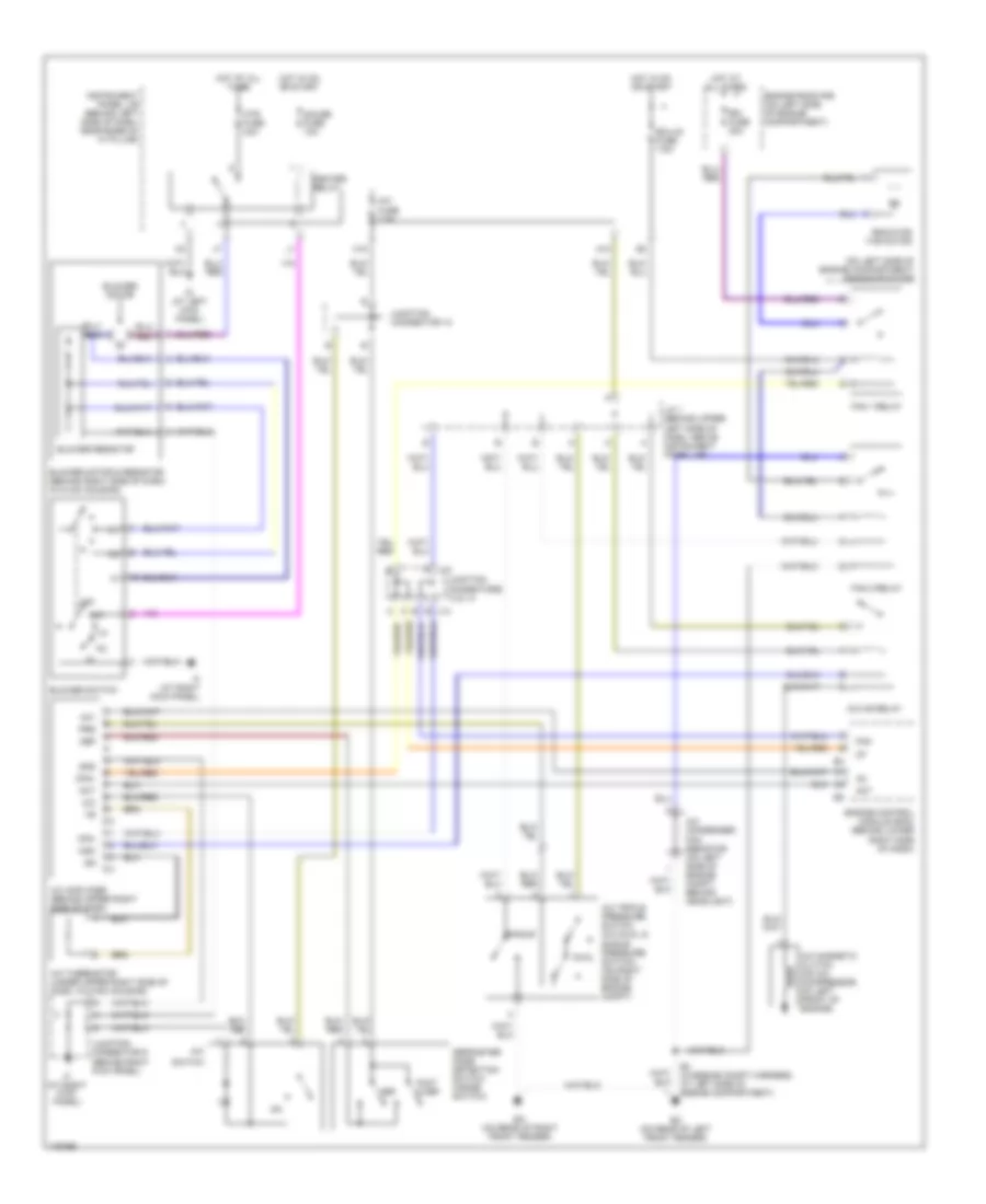
AIR CONDITIONING
Heater Wiring Diagram for Toyota ECHO 2003
 https://portal-diagnostov.com/license.html
Automotive Electricians Portal FZCO
Automotive Electricians Portal FZCO
https://portal-diagnostov.com/license.html
https://portal-diagnostov.com/license.html
Automotive Electricians Portal FZCO
Automotive Electricians Portal FZCO
List of elements for Heater Wiring Diagram for Toyota ECHO 2003:
- A/c fuse 7.5a
- Air inlet control servo motor (under upper right side of dash, on hvac housing)
- Alt
- Blower motor
- Blower motor & resistor (behind right side of dash, in hvac housing)
- Blower resistor
- Blower switch
- Control circuit
- Ecu-ig fuse 7.5a
- Els
- Engine control module (ecm) (behind lower right side of dash)
- Engine room r/b (on left side of engine compartment)
- F/d
- Foot
- Foot mode switch
- Frs
- G10
- Gauge fuse 10a
- Generator
- Gnd
- H11
- Heater relay
- Heater sub 1 relay
- Hot at all times
- Hot in on or start
- Htr fuse 40a
- Htr sub 1 fuse 50a
- Id (at left kick panel)
- If (at right kick panel)
- Inlet air position detection switch (inside switch)
- Instrument panel j/b (behind left side of dash, near base of ``a" pillar)
- Junction connector
- Junction connector 9 (behind right kick panel)
- Max hot
- Max hot & foot mode switch
- Max hot switch
- Mhsw
- Mode in
- Off
- Position switches
- Ptc amplifier (behind upper right side of dash, near instrument cluster)
- Ptc heater (behind left center of dash)
- Ptc1
- R/f1
- Rec
- Rec/frs
- Red
- Taco
- Tw1
- W/ tacho- meter
- W/o tacho- meter
- Water temperature sensor (behind upper right side of dash)
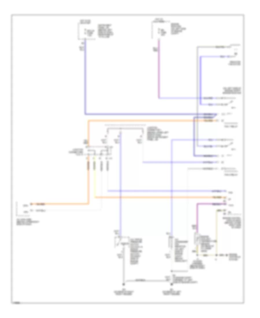
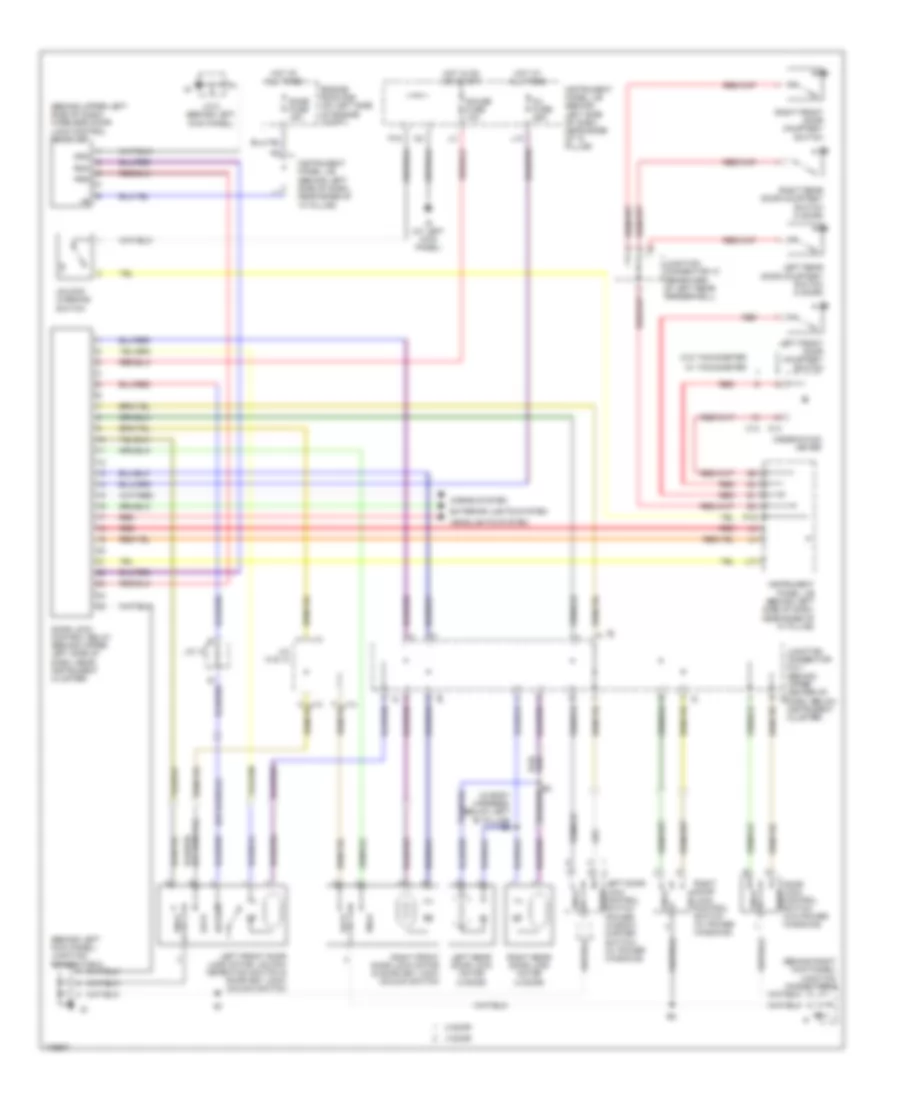
Manual A/C Wiring Diagram for Toyota ECHO 2003
List of elements for Manual A/C Wiring Diagram for Toyota ECHO 2003:
- (on left side of engine compartment) engine room r/b
- A/c
- A/c amplifier (behind upper right side of dash)
- A/c condenser fan resistor (on left side of engine compt, behind headlight)
- A/c fuse 7.5a
- A/c magnetic clutch (on a/c compressor, on left front of engine)
- A/c mg relay
- A/c thermistor (under upper right side of dash, in hvac housing)
- A/c triple pressure switch (a/c dual & single pressure dual switch) (on right side of engine compt)
- A10
- Ac1
- Act
- Blower motor
- Blower motor & resistor (behind right side of dash, in hvac housing)
- Blower resistor
- Blower switch
- Cfn+
- Cfn-
- Def
- Defroster mode detection switch (inside switch)
- E4 (in engine compt harness, at left side of engine compartment)
- Ea (on rear of right front fender)
- Ec (on rear of left front fender)
- Ecu-ig fuse 7.5a
- Engine control module (ecm) (behind lower right side of dash)
- Engine room r/b (on left side of engine compartment)
- Fan
- Fan 1 relay
- Fan 2 relay
- Foot & def
- Gauge fuse 10a
- Gnd
- H18
- Heater relay
- Hot at all times
- Hot in on or start
- Htr fuse 40a
- Id (at left kick panel)
- If (at right kick panel)
- Instrument panel j/b (behind left side of dash, near base of ``a" pillar)
- J/c 1 (behind upper left side of dash, above instrument panel j/b)
- J13
- J14
- Junction connector 12
- Junction connector 9 (behind right kick panel)
- Junction connectors 13 & 14
- Mgc
- Off
- Prs
- Radiator fan motor
- Rdi fuse 30a
- Single
- Switch
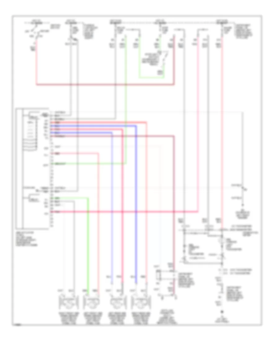
ANTI-LOCK BRAKES
Anti-lock Brakes Wiring Diagram for Toyota ECHO 2003
List of elements for Anti-lock Brakes Wiring Diagram for Toyota ECHO 2003:
- (w/ tachometer)
- (w/o tachometer)
- +bm
- Abs actuator w/ ecu (on left side of engine compt, near brake master cylinder)
- Abs fuse 60a
- Abs warning light (w/ tachometer
- Abs warning light (w/o tachometer
- Acc
- C13
- C14
- Combination meter
- D/g
- Data link connector (dlc) 3 (under left side of dash, near kick panel)
- Ec (on rear of left front fender)
- Ecu-ig fuse 7.5a
- F12
- Fl+
- Fl-
- Fr+
- Fr-
- Fusible link block (on left side of engine compt)
- G13
- Gauge fuse 10a
- Gnd1 +bs
- Gnd2
- Hot at all times
- Hot in on or start
- Id (at left kick panel)
- Ig1
- Ignition switch
- Instrument panel j/b (behind left side of dash, near base of "a" pillar)
- Left front abs speed sensor (mounted on left front wheel hub)
- Left rear abs speed sensor (mounted on left rear wheel hub)
- Off
- P10
- Pnk
- Red
- Relay
- Right front abs speed sensor (mounted on right front wheel hub)
- Right rear abs speed sensor (mounted on right rear wheel hub)
- Rl+
- Rl-
- Rr+
- Rr-
- Sil
- Start
- Stop fuse 10a
- Stoplight switch (on bracket, above brake pedal)
- Stp
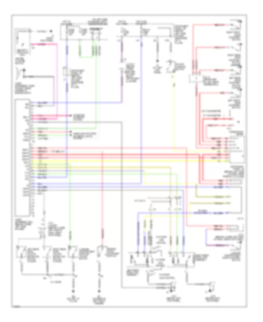
ANTI-THEFT
Anti-theft Wiring Diagram for Toyota ECHO 2003
List of elements for Anti-theft Wiring Diagram for Toyota ECHO 2003:
- (on left side of engine compt) engine room r/b
- +b1
- +b2
- Bg (on left "c" pillar)
- C14
- Center cluster switch
- Combination meter
- Control
- D/l fuse 25a
- D15
- D17
- Detect
- Dome fuse 15a
- Dswd
- Dswh
- Dswl
- Dswp
- Ec (on rear of left front fender)
- Ecu-ig fuse 7.5a
- Engine hood courtesy switch
- Exterior lights system
- H11
- Head
- Headlights system
- Horn
- Horn fuse 15a
- Horn relay
- Hot at all times
- Hot in on or start
- Id (at left kick panel)
- If (right kick panel)
- Ind
- Instrument panel j/b (behind left side of dash, near base of "a" pilaar)
- Instrument panel j/b (behind left side of dash, near base of "a" pillar)
- J/c 10 (rearward of left rear fenderwell)
- J/c 12
- J/c 13 & 14
- J/c 3 (behind lower left side of dash, near kick panel)
- J/c 4 (4 door) (behind lower left side of dash, near kick panel)
- J/c 5 (behind left kick panel)
- J/c 6 & 7 (behind upper center j6
- J/c 9 (behind right kick panel)
- J13
- J14
- Ksw
- L10
- L13
- Left front door courtesy switch
- Left front door lock assembly
- Left rear door courtesy switch (4 door)
- Left rear door unlock detection switch (4 door)
- Lock
- Lock control
- Lswd
- Lswp
- Lswr
- Lug
- Luggage compartment door courtesy switch
- Luggage compartment door key unlock switch
- Of dash, below instrument cluster)
- P16
- P19
- Pnk
- Red
- Right front door courtesy switch
- Right front door lock assembly
- Right rear door courtesy switch (4 door)
- Right rear door unlock detection switch (4 door)
- Security indicator light
- Sh-
- Srly
- Starting/ charging system
- Tail
- Theft deterrent ecu (behind upper left side of dash)
- Theft deterrent horn (in right rear corner of engine compt)
- Ul2
- Ul3
- Unlk
- Unlock warning switch
- W/ 4 door
- W/ door
- W/ tachometer
- W/o door
- W/o tachometer
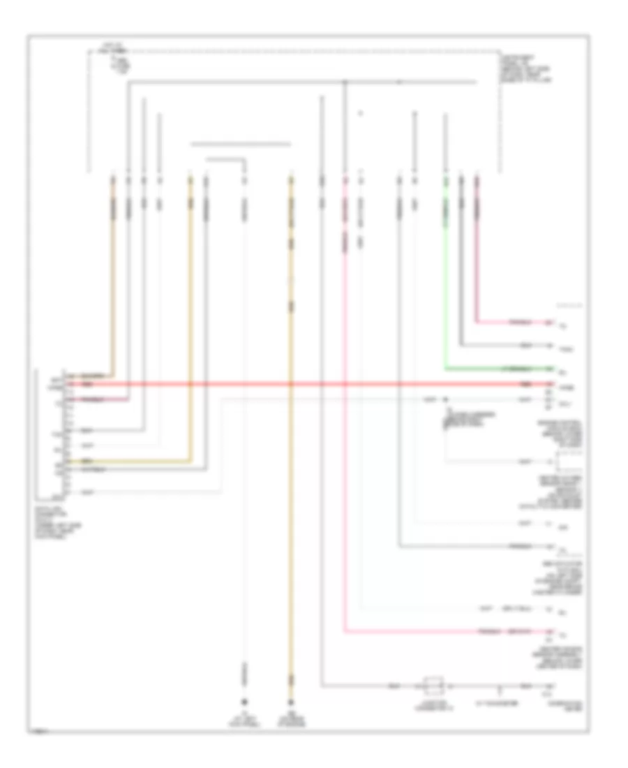
COMPUTER DATA LINES
Computer Data Lines Wiring Diagram for Toyota ECHO 2003
List of elements for Computer Data Lines Wiring Diagram for Toyota ECHO 2003:
- Abs actuator with ecu (on left side of engine compt, near brake master cylinder)
- Bat
- C13
- Center air bag sensor assembly (behind lower center of dash)
- Combination meter
- D/g
- Data link connector (dlc) 3 (under left side of dash, near kick panel)
- Eb (on rear of engine)
- Engine control module (ecm) (behind lower right side of dash)
- G10
- H12
- H14
- Heated oxygen sensor (bank 1 sensor 1) (on exhaust system, before catalytic converter)
- Hot at all times
- Id (at left kick panel)
- Instrument panel j/b (behind left side of dash, near base of "a" pillar)
- Junction connector 12
- Obd fuse 7.5a
- Ox1
- Oxl1
- P17
- Red
- Sil
- Tac
- Tach
- W/ tachometer
- Wfse
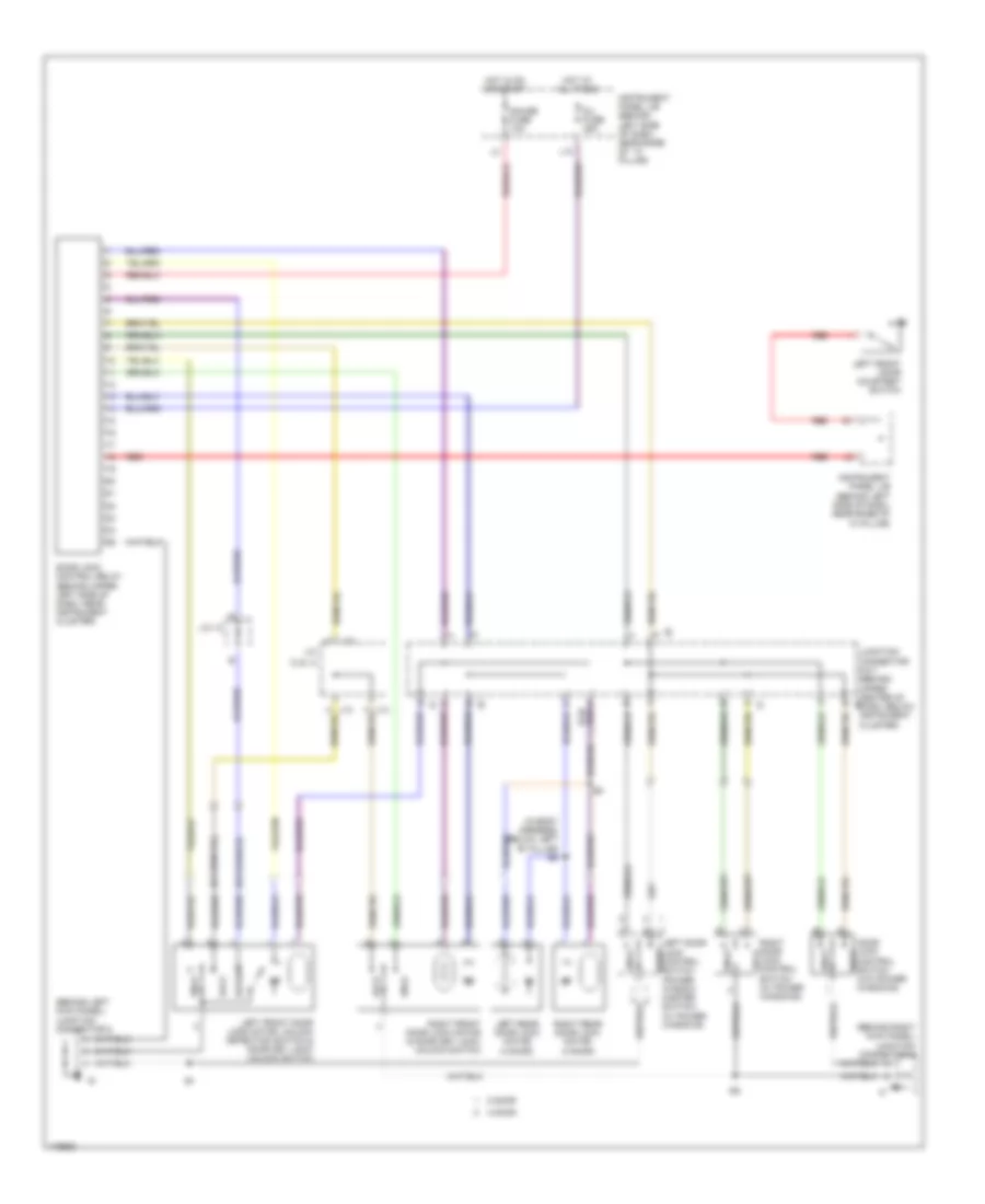
COOLING FAN
Cooling Fan Wiring Diagram for Toyota ECHO 2003
List of elements for Cooling Fan Wiring Diagram for Toyota ECHO 2003:
- (on left side of engine compt) engine room r/b
- A/c amplifier (behind upper right side of dash)
- A/c condenser fan resistor (on left side of engine compt, behind headlight)
- A/c triple pressure switch (a/c dual & single pressure switch) (on right side of engine compt)
- Cfn+
- Cfn-
- E4 (in engine compt harness, at left side of engine compt)
- Ea (on rear of right front fender)
- Ec (on rear of left front fender)
- Ecu-ig fuse 7.5a
- Engine control module (ecm) (behind lower right side of dash)
- Engine controls
- Engine coolant temperature sensor (on rear of cylinder head)
- Engine room r/b (on left side of engine compt)
- Fan
- Fan 1 relay
- Fan 2 relay
- Hot at all times
- Hot in on or start
- I4 (in dash harness, behind right side of dash)
- Instrument panel j/b (behind left side of dash, near base of ``a" pillar)
- J13
- J14
- Junction connector 1 (behind upper left side of dash, above instrument panel j/b)
- Junction connectors 13 & 14
- Radiator fan motor
- Rdi fuse 30a
- Single
- System
- Thw
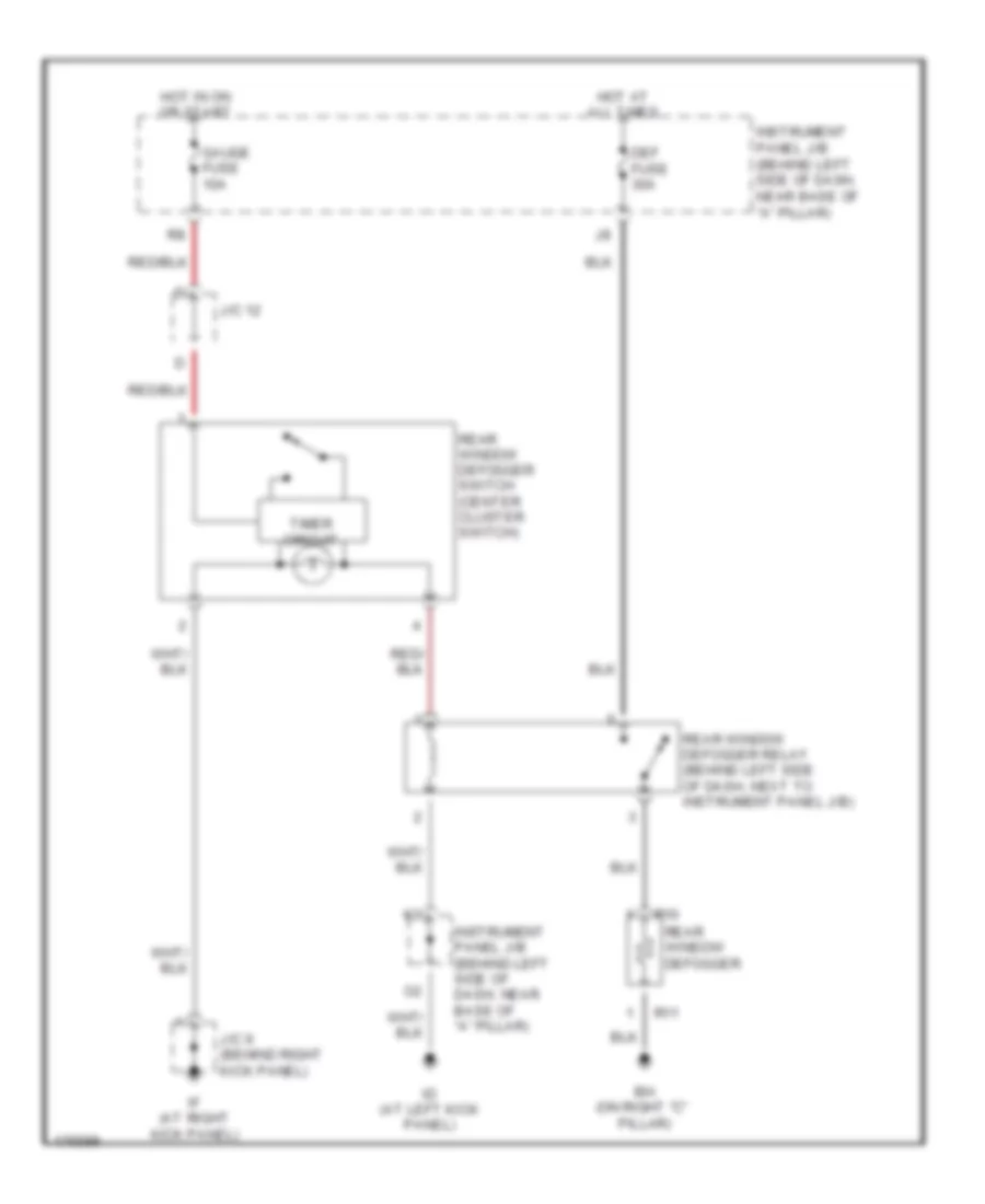
DEFOGGERS
Defoggers Wiring Diagram for Toyota ECHO 2003
List of elements for Defoggers Wiring Diagram for Toyota ECHO 2003:
- Bh (on right "c" pillar)
- Def fuse 30a
- Gauge fuse 10a
- Hot at all times
- Hot in on or start
- Id (at left kick panel)
- If (at right kick panel)
- Instrument panel j/b (behind left side of dash, near base of "a" pillar)
- J/c 12
- J/c 9 (behind right kick panel)
- R10
- R11
- Rear window defogger
- Rear window defogger relay (behind left side of dash, next to instrument panel j/b)
- Rear window defogger switch (center cluster switch)
- Timer circuit
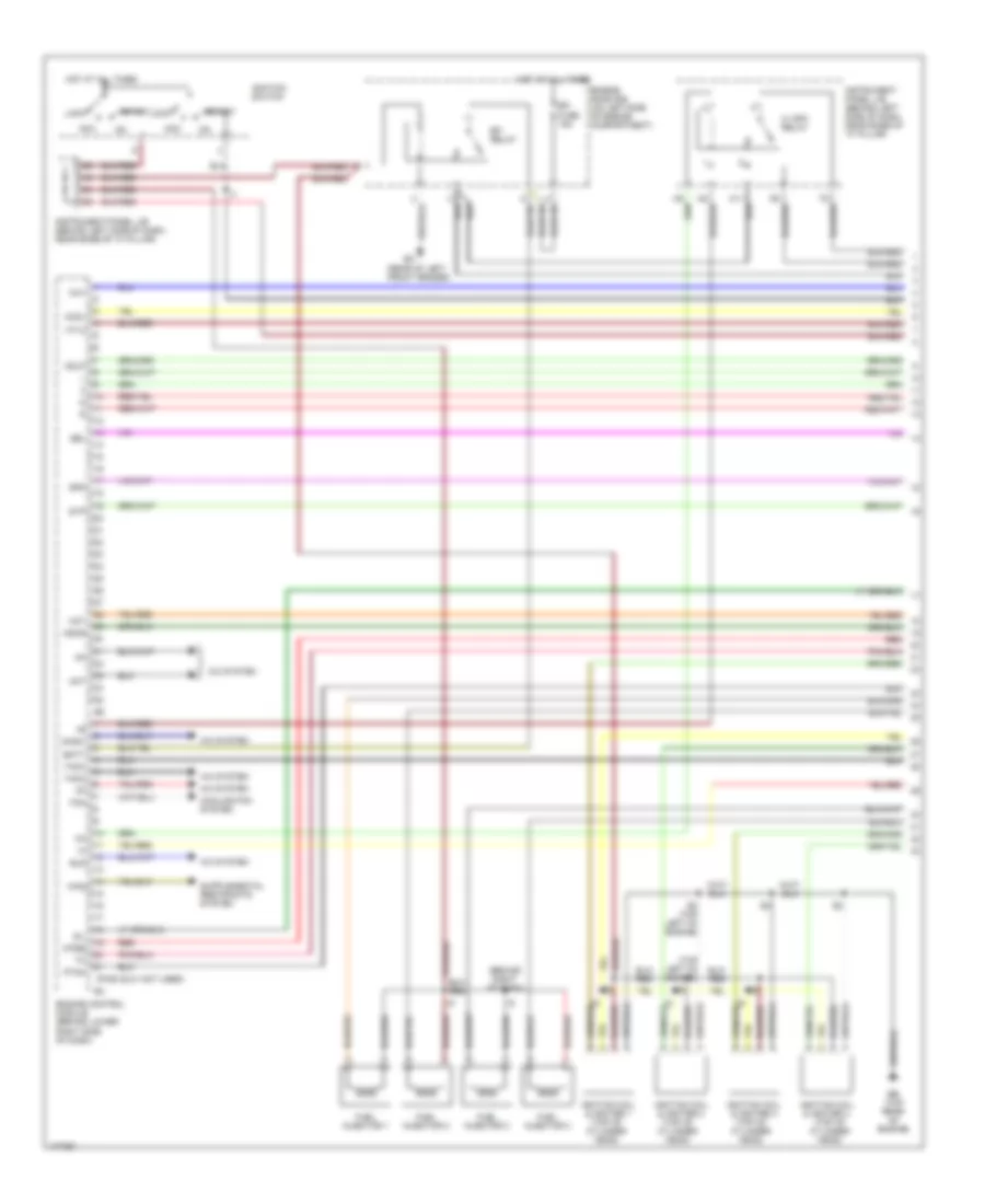
ENGINE PERFORMANCE
1.5L
1.5L, Engine Performance Wiring Diagram (1 of 4) for Toyota ECHO 2003
List of elements for 1.5L, Engine Performance Wiring Diagram (1 of 4) for Toyota ECHO 2003:
- (behind right of dash)
- (pins 22-31 not used)
- (rear of left front fender)
- (top left of engine)
- A/c system
- Acc
- Act
- Batt
- C/ opn relay
- Ccv
- Cool
- Cooling fan system
- E3 (top left of engine)
- Eb (top rear of engine)
- Efi fuse 15a
- Efi relay
- Els
- Engine control module (behind lower right side of dash)
- Engine room r/b (on left side of engine compartment)
- F/ps
- Fan
- Fuel injector 1
- Fuel injector 2
- Fuel injector 3
- Fuel injector 4
- Hot
- Hot at all times
- Htl2
- Ignition coil & igniter 1 (top of cylinder head)
- Ignition coil & igniter 2 (top of cylinder head)
- Ignition coil & igniter 3 (top of cylinder head)
- Ignition coil & igniter 4 (top of cylinder head)
- Ignition switch
- Instrument panel j/b (behind left side of dash, near base of "a" pillar)
- Lock
- Mhsw
- Odlp
- Odms
- Ptnk
- Red
- Sel
- Sil
- Spd
- Start
- Stp
- Tach
- Taco
- Wfse
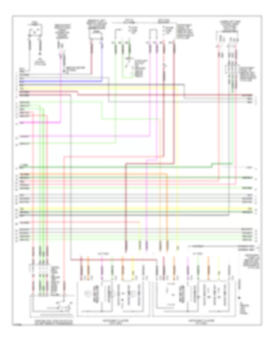
1.5L, Engine Performance Wiring Diagram (2 of 4) for Toyota ECHO 2003
List of elements for 1.5L, Engine Performance Wiring Diagram (2 of 4) for Toyota ECHO 2003:
- (behind center of dash) ie
- (behind right side of dash) check connector (power steering)
- (beneath left rear of vehicle) vsv (canister closed valve)
- (under left side of dash, near kick panel) data link connector 3
- Bg (on left "c" pillar)
- C13
- C14
- Duty
- F12
- Fuel pump
- Gauge fuse 10a
- Gnd
- H12
- H13
- H14
- H16
- Hot at all times
- Hot in on or start
- Id (behind left kick panel)
- Indicator lamp malfunction
- Instru- ment panel j/b (behind left side of dash, near base of a- pillar)
- Instrument cluster (w/ tach)
- Instrument cluster (w/o tach)
- Instrument panel j/b (behind left side of dash, near base of "a" pillar)
- Malfunction indicator lamp
- O/d off indicator
- Ox1
- Park/neutral position switch (on left rear of transmission)
- Red
- Sil
- Speedometer
- Stop fuse 10a
- Stoplight switch (on bracket, above brake pedal)
- Tac
- W/ tach
- W/o tach
- Water temp cool
- Water temp hot
- Wfse
1.5L, Engine Performance Wiring Diagram (3 of 4) for Toyota ECHO 2003
List of elements for 1.5L, Engine Performance Wiring Diagram (3 of 4) for Toyota ECHO 2003:
- (on left front of engine) camshaft timing oil control valve
- Camshaft position sensor (on rear of cylinder head)
- Crankshaft position sensor (on front lower left of engine)
- Duty
- E01
- E02
- Eb (rear of engine)
- Engine control module (behind lower right side of dash)
- Gnd
- I3 (dash harn, behind right side of dash)
- Idle air control valve (on left rear of engine)
- Igf
- Igt2
- Igt3
- Igt4
- Nca
- Ne-
- Ocv+
- Ocv-
- Of dash) i8
- Ogt1
- Oil
- Prg
- Rsd
- Slt+
- Slt-
- Tha
- Thw
- Visc
- Vsv (evap) (on left side of engine compartment, near brake master cylinder)
- Vta
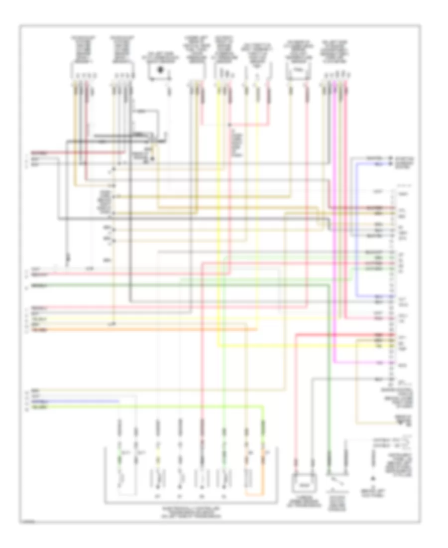
1.5L, Engine Performance Wiring Diagram (4 of 4) for Toyota ECHO 2003
List of elements for 1.5L, Engine Performance Wiring Diagram (4 of 4) for Toyota ECHO 2003:
- (dash harn, behind right side of dash) i4
- (on exhaust system) heated oxygen sensor (bank 1, sensor 1)
- (on exhaust system) heated oxygen sensor (bank 1, sensor 2)
- (on left side of cylinder block) knock sensor
- (on left side of engine compartment, near battery) mass air- flow meter
- (on rear of cylinder head) engine coolant temperature sensor
- (on right front of engine) power steering oil pressure sensor
- (on throttle body assembly) throttle position sensor
- (rear of engine) eb
- (under left rear of vehicle, near fuel tank) vapor pressure sensor
- Alt
- E03
- E2g
- Electronically controlled transmission solenoid (on left side of transmission)
- Engine control module (behind lower right side of dash)
- Evg
- Gnd
- Htl
- I5 (dash harn, right side of dash)
- Id (behind left kick panel)
- Instrument panel j/b (behind left side of dash, near base of "a" pillar)
- Knk1
- Nca
- Nsw
- Nt+
- Nt-
- O/d main switch (center console)
- Oxl1
- Oxl2
- P13
- Pnk
- Psp
- Red
- Slt+
- Slt-
- Sta
- Starting/ charging system
- Tha
- Turbine speed sensor (on transmission)
- Vout
EXTERIOR LIGHTS
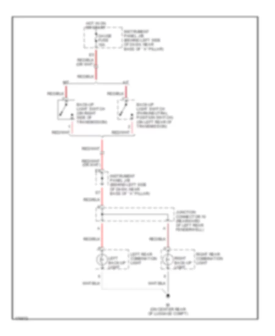
Back-up Lamps Wiring Diagram for Toyota ECHO 2003
List of elements for Back-up Lamps Wiring Diagram for Toyota ECHO 2003:
- A/t
- Back-up light switch (on right side of transmission)
- Back-up light switch (park/neutral position switch) (on left rear of transmission)
- Bi (on center rear of luggage compt)
- Gauge fuse 10a
- Hot in on or start
- Instrument panel j/b (behind left side of dash, near base of ``a" pillar)
- Junction connector 10 (rearward of left rear fenderwell)
- Left back-up light
- Left rear combination light
- M/t
- Right back-up light
- Right rear combination light
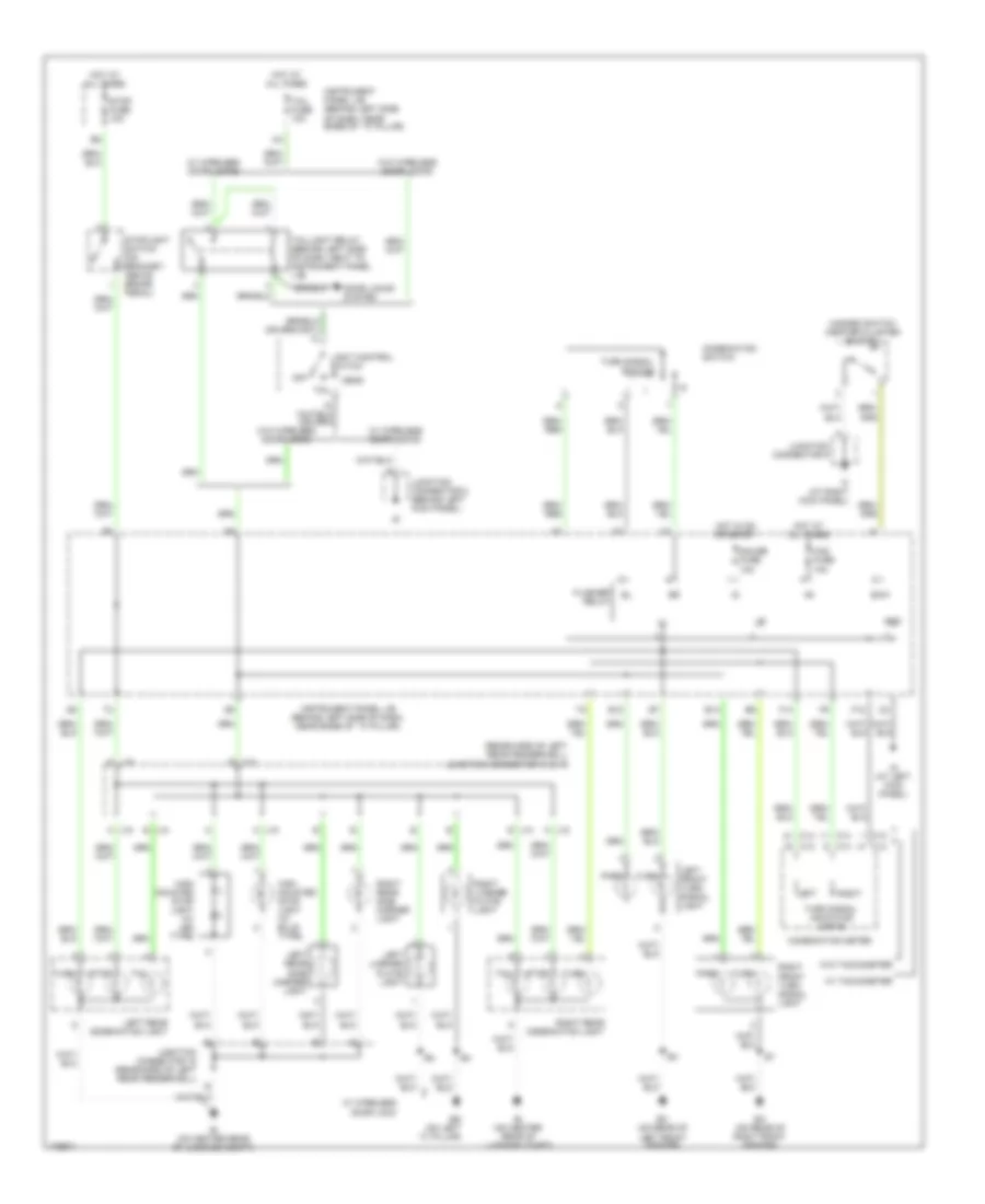
Exterior Lamps Wiring Diagram for Toyota ECHO 2003
List of elements for Exterior Lamps Wiring Diagram for Toyota ECHO 2003:
- (rearward of left rear fenderwell) junction connector 10 & 15
- A j15
- B12
- B13
- Bg (on left ``c" pillar)
- Bi (on center rear of luggage compt)
- C13
- C14
- Combination meter
- Combination switch
- Door locks system
- E j10
- Ea (on rear of right front fender)
- Ec (on rear of left front fender)
- Ehw
- F12
- F14
- Flasher relay
- Gauge fuse 10a
- Gnd
- Haz fuse 10a
- Hazard switch (center cluster switch)
- Head
- High mounted stop light (w/ bulb type)
- High mounted stop light (w/ led type)
- Hot at all times
- Hot in on or start
- Id (at left kick panel)
- If (at right kick panel)
- Instrument panel j/b (behind left side of dash, near base of ``a" pillar)
- Junction connector 15 (rearward of left rear fenderwell)
- Junction connector 5 (behind left kick panel)
- Junction connector 9
- Left
- Left front turn signal light
- Left license plate light
- Left rear combination light
- Left rear side marker light
- Light control switch
- Off
- Park
- Right
- Right front turn signal light
- Right license plate light
- Right rear combination light
- Right rear side marker light
- Stop
- Stop fuse 10a
- Stoplight switch (on bracket, above brake pedal)
- Tail
- Tail fuse 10a
- Taillight relay (behind left side of dash, next to instrument panel j/b)
- Turn
- Turn signal indicator lights
- Turn signal switch
- W/ tachometer
- W/ wireless door lock
- W/ wireless door locks
- W/o tachometer
- W/o wireless door locks
GROUND DISTRIBUTION
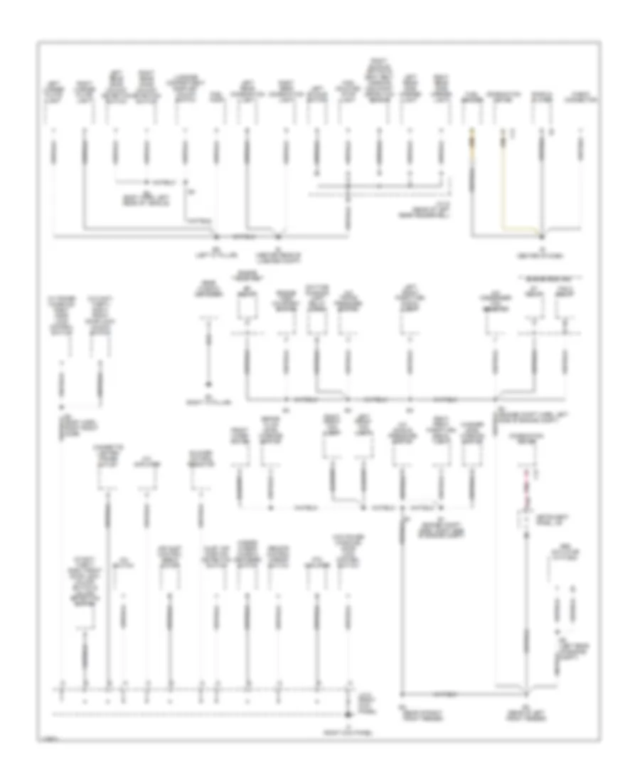
Ground Distribution Wiring Diagram (1 of 2) for Toyota ECHO 2003
List of elements for Ground Distribution Wiring Diagram (1 of 2) for Toyota ECHO 2003:
- (center of dash)
- (rear of right front fender)
- (w/ power windows) right door lock control switch
- (w/anti- theft) right front door lock/ unlock switch & unlock detection switch
- (w/o anti- theft) right front door lock/ unlock switch
- (w/o power windows) door lock control switch
- A/c amplifier
- A/c condenser fan resistor
- A/c single pressure switch
- A/c switch
- A/c triple pressure switch
- Abs actuator with ecu
- Air inlet control servo motor
- B2 (body harn, right front door)
- B4 (body harn, left rear of vehicle)
- B4 (right "c" pillar)
- Bg (left "c" pillar)
- Bi (center rear of luggage compt)
- Blower motor & resistor
- Brake fluid level warning switch
- C13
- C14
- Check connector
- Cigarette lighter/ power outlet
- Combination meter
- Daytime running light relay (main)
- E1 (engine compt harn, right side of engine compt)
- E4 (engine compt harn, left side of engine compt)
- E5 (left rear of engine compt)
- Ec (rear of left front fender)
- Efi relay
- Engine hood courtesy switch
- Engine room r/b
- Fan 2 relay
- Front wiper motor
- Fuel pump
- Fuel sender
- Hazard & rear window defogger switch
- High mounted stop light
- If (right kick panel)
- Inlet air position detection switch
- Instrument panel j/b
- J/c 15 (rear of left rear fenderwell)
- J/c 9 (right kick panel)
- Left buckle switch
- Left front fog light
- Left front park/turn signal light
- Left license plate light
- Left rear combination light
- Left rear door unlock detection switch
- Left rear side marker light
- Luggage compartment door key unlock switch
- P10
- Pnk
- Ptc amplifier
- Radio & player
- Rear window defogger
- Remote control mirror switch
- Right buckle switch & seat belt warning occupant detection sensor
- Right front fog light
- Right front park/turn signal light
- Right license plate light
- Right rear combination light
- Right rear door unlock detection switch
- Right rear side marker light
- St relay
- Washer level warning switch
Ground Distribution Wiring Diagram (2 of 2) for Toyota ECHO 2003
List of elements for Ground Distribution Wiring Diagram (2 of 2) for Toyota ECHO 2003:
- 2 door
- 4 door
- B1 (body harn, left front door)
- Blower switch, right front seat belt warning light, security indicator light
- C14
- Camshaft position sensor shield
- Center airbag sensor assembly
- Center cluster switch
- Clock
- Combination meter
- Crankshaft position sensor shield
- Data link connector
- Door lock control relay
- E3 (engine harn, left rear of engine)
- Eb (rear of engine)
- Engine control module
- F12
- Flasher relay
- Front wiper & washer switch
- Headlight relay
- Heated oxygen sensor (bank 1 sensor 1)
- Heated oxygen sensor (bank 1 sensor 2)
- Heated oxygen sensor shield
- Heater relay
- I2 (dash harn, right side of dash)
- I5 (dash harn, right side of dash)
- I6 (dash harn, right side of dash)
- Id (left kick panel)
- Idle air control valve
- If (right kick panel)
- Ignition coil & igniter
- Instrument panel j/b
- J/c 5 (left kick panel)
- Knock sensor shield
- Left door lock control switch (w/ power windows)
- Left front door lock/ unlock switch & unlock detection switch
- Light control & dimmer switch
- Light control switch (combination switch)
- N11
- N13
- Nca
- O/d main switch
- P13
- P15
- P16
- P17
- Power relay
- Power window master switch
- Rear window defogger relay
- Rheostat
- Shift lock control switch
- Theft deterrent ecu
- Turn signal switch
- Unlock warning switch
- Wireless door lock control receiver
HEADLIGHTS
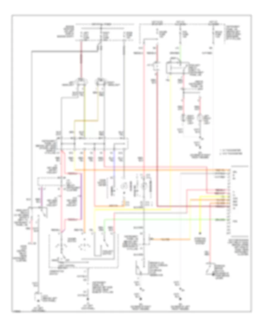
Headlights Wiring Diagram, with DRL for Toyota ECHO 2003
List of elements for Headlights Wiring Diagram, with DRL for Toyota ECHO 2003:
- (above instrument panel j/b)
- B10
- B11
- Beam ind
- Brake fluid level warning switch (on brake fluid reservoir)
- Brake ind
- Brk
- C13
- C14
- Chg
- Comb- ination meter
- Combination switch
- Daytime running light relay (main) (behind upper left side of dash, near instrument cluster)
- Dimmer switch
- Dome fuse 15a
- Door lock control relay (near instrument cluster)
- Drl
- Ea (on rear of right front fender)
- Ec (on rear of left front fender)
- Ecu-b fuse 7.5a
- Engine room r/b (on left side of engine compt)
- Fog
- Fog fuse 15a
- Foglight relay (next to instrument panel j/b)
- Foglight switch
- G12
- G13
- Gauge fuse 10a
- Head
- Headlight relay (w/ keyless entry) (next to instrument panel j/b)
- Hot at all times
- Hot in on or start
- Id (at left kick panel)
- Instrument panel j/b (behind left side of dash, near base of "a" pillar)
- J/c 1
- J/c 12
- J/c 5 (behind left kick panel)
- J/c 6 & 7 (below instrument cluster)
- J10
- Left front fog- light
- Left h-lp fuse 10a
- Left headlight
- Light control switch
- Off
- Parking brake switch (on base of park brake lever)
- Pkb
- R10
- Red
- Right front fog- light
- Right h-lp fuse 10a
- Right headlight
- Starting/ charging system
- Tail
- W/ keyless entry/ foglight
- W/ tachometer
- W/o keyless entry/ foglight
- W/o tachometer
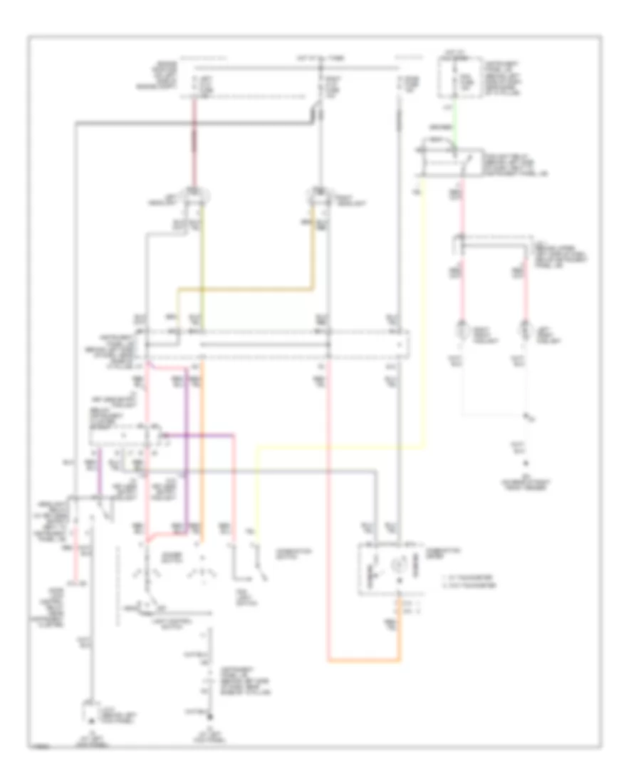
Headlights Wiring Diagram, without DRL for Toyota ECHO 2003
List of elements for Headlights Wiring Diagram, without DRL for Toyota ECHO 2003:
- (below instrument cluster) j/c 6 & 7
- B10
- B11
- Beam ind
- C14
- Combination meter
- Combination switch
- Dimmer switch
- Dome fuse 15a
- Door lock control relay (near instrument cluster)
- Ea (on rear of right front fender)
- Engine room r/b (on left side of engine compt)
- Fog fuse 15a
- Fog light switch
- Foglight relay (behind left side of dash, next to instrument panel j/b)
- G12
- Head
- Headlight relay (w/ keyless entry) (next to instrument panel j/b)
- Hot at all times
- Id (at left kick panel)
- Instrument panel j/b (behind left side of dash, near base of "a" pillar)
- J/c 1 (behind upper left side of dash, above instrument panel j/b)
- J/c 5 (behind left kick panel)
- J10
- Left front foglight
- Left h-lp fuse 10a
- Left headlight
- Light control switch
- Off
- Red
- Right front foglight
- Right h-lp fuse 10a
- Right headlight
- Tail
- W/ keyless entry/ foglight
- W/ tachometer
- W/o keyless entry/ foglight
- W/o tachometer
HORN
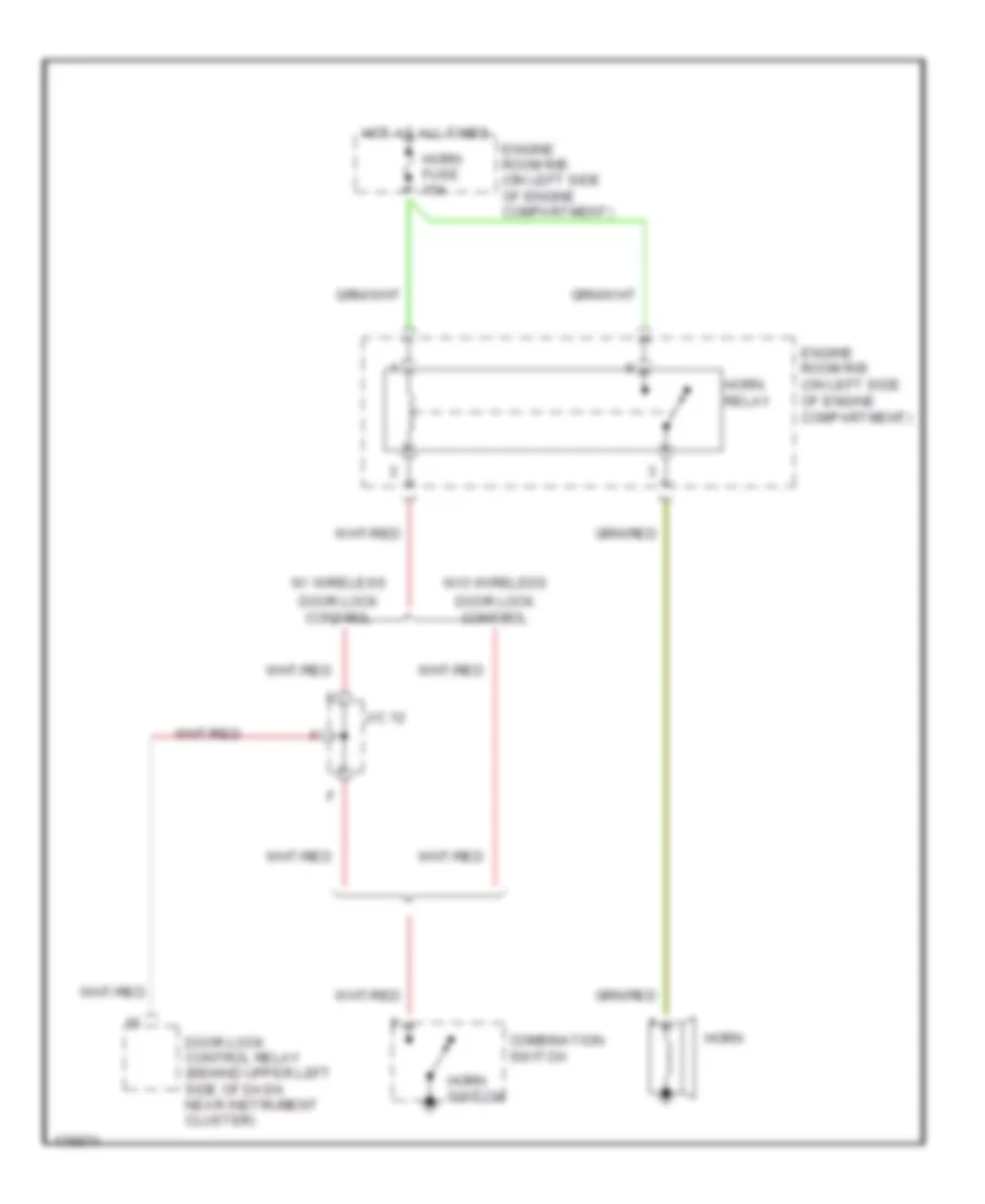
Horn Wiring Diagram for Toyota ECHO 2003
List of elements for Horn Wiring Diagram for Toyota ECHO 2003:
- Combination switch
- Door lock control
- Door lock control relay (behind upper left side of dash, near instrument cluster)
- Engine room r/b (on left side of engine compartment)
- Horn
- Horn fuse 15a
- Horn relay
- Horn switch
- Hot at all times
- J/c 12
- W/ wireless
- W/o wireless
INSTRUMENT CLUSTER
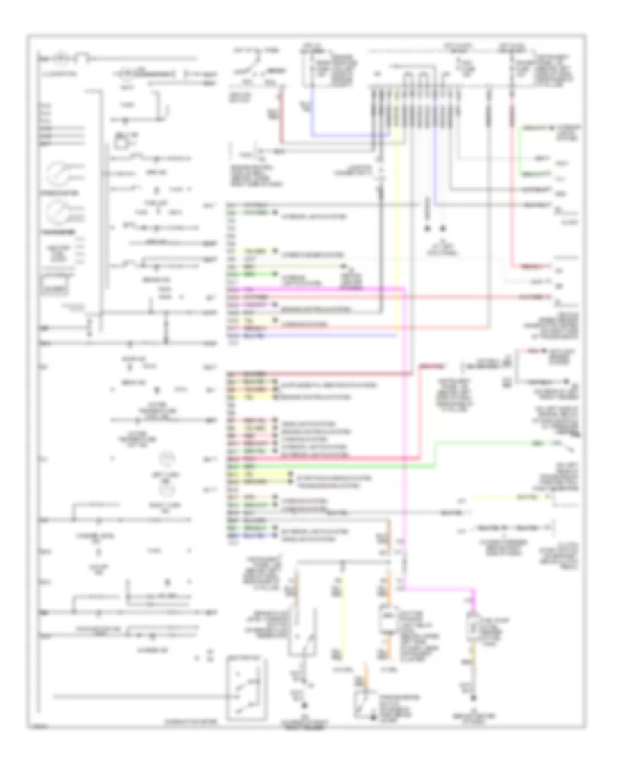
Instrument Cluster Wiring Diagram, with Tachometer for Toyota ECHO 2003
List of elements for Instrument Cluster Wiring Diagram, with Tachometer for Toyota ECHO 2003:
- (on left rear of transmission) park/neutral position switch
- (on left side of engine, below intake manifold) oil pressure switch
- A/t
- A10
- A11
- A12
- A13
- A14
- A15
- A16
- A17
- A18
- Abs ind
- Acc
- Acc fuse 15a
- Acc+
- Anti-lock brakes system
- B10
- B11
- B12
- B13
- B14
- B15
- B16
- B17
- B18
- B19
- B20
- B21
- B22
- Beam ind
- Belt ind
- Brake fluid level warning switch (on brake fluid reservoir)
- Brake ind
- Brk
- Buzzer
- C13
- C14
- Charge ind
- Clock
- Clutch start switch (on bracket, above clutch pedal)
- Combination meter
- Daytime running light relay (main) (behind upper left side of dash, near instrument cluster)
- Dome fuse 15a
- Door ind
- Ea (on rear of right front fender)
- Ec (on rear of left front fender)
- Engine control module (ecm) (behind lower right side of dash)
- Engine controls system
- Engine room r/b (on left side of engine compt)
- Exterior lights system
- F12
- Fuel ind
- Fuel pump & fuel sender (in fuel tank)
- G10
- G12
- G13
- Gauge fuse 10a
- Gnd
- Headlights system
- Hot at all times
- Hot in acc or on
- Hot in on or start
- I7 (in dash harness, behind right side of dash)
- Id (at left kick panel)
- Ie (behind center of dash)
- Ig+
- Ignition switch
- Ill+
- Illumination
- Instrument panel j/b (behind left side of dash, near base of "a" pillar)
- Interior lights system
- Junction connector 12
- K10
- K12
- Lcd display
- Lcd illumination
- Left turn ind
- Lock
- M/t
- Malfunction ind lamp
- O/d off ind
- Odo/trip fuel clock
- Odo/trip sw
- Oil ind
- P10
- Parking brake switch (on base of park brake lever)
- Pkb
- Pnk
- Red
- Right turn ind
- Run
- Speedometer
- Srs ind
- Start
- Starting/charging system
- Tachometer
- Taco
- Transmissions system
- Vehicle speed sensor (combination meter) (on right side of transmission)
- W/ abs
- W/ drl
- W/o abs
- W/o drl
- Warning system
- Washer level ind
- Water temperature cool ind
- Water temperature hot ind
- Wiper/washer system
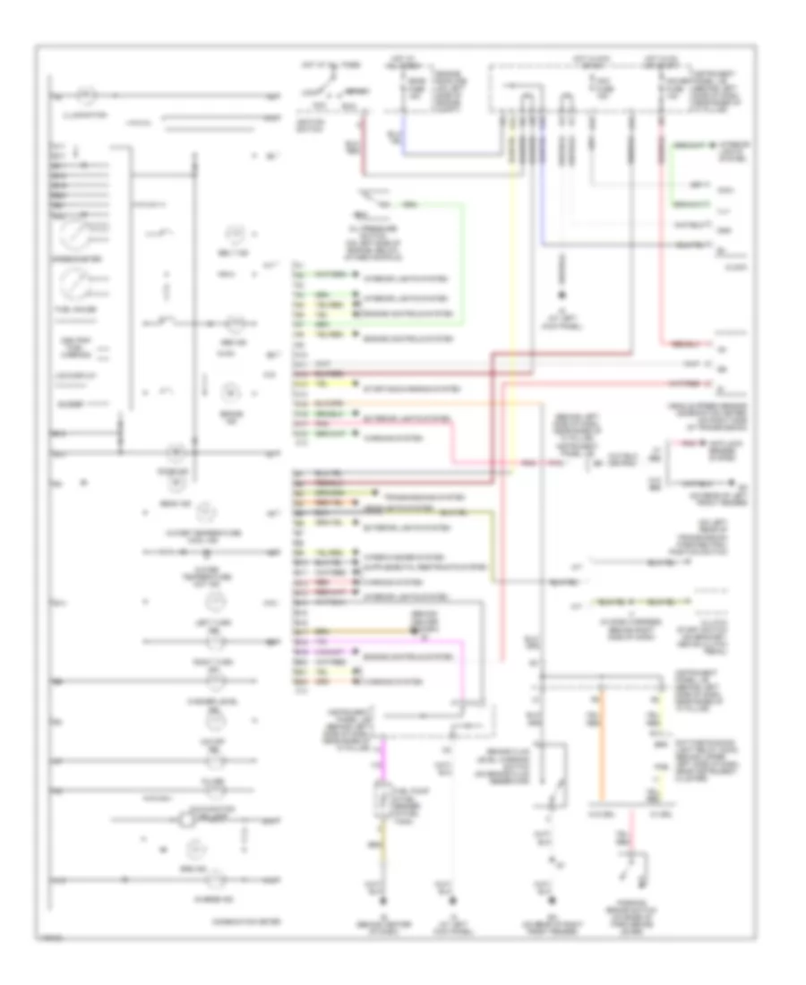
Instrument Cluster Wiring Diagram, without Tachometer for Toyota ECHO 2003
List of elements for Instrument Cluster Wiring Diagram, without Tachometer for Toyota ECHO 2003:
- (behind center of dash)
- (behind left side of dash, near base of "a" pillar) instrument panel j/b
- (on left rear of transmission) park/neutral position switch
- A/t
- A10
- A11
- A12
- A13
- A14
- A15
- A16
- A17
- A18
- Abs ind
- Acc
- Acc fuse 15a
- Acc+
- Anti-lock brakes system
- B10
- B11
- B12
- B13
- B14
- B15
- B16
- B17
- B18
- B19
- B20
- B21
- B22
- Beam ind
- Belt ind
- Brake fluid level warning switch (on brake fluid reservoir)
- Brake ind
- Brk
- Buzzer
- C13
- C14
- Charge ind
- Clock
- Clutch start switch (on bracket, above clutch pedal)
- Combination meter
- Daytime running light relay (main) (behind upper left side of dash, near instrument cluster)
- Dome fuse 15a
- Door ind
- Ea (on rear of right front fender)
- Ec (on rear of left front fender)
- Engine controls system
- Engine room r/b (on left side of engine compt)
- Exterior lights system
- F12
- Fuel gauge
- Fuel pump & fuel sender (in fuel tank)
- G12
- G13
- Gauge fuse 10a
- Gnd
- Headlights system
- Hot at all times
- Hot in acc or on
- Hot in on or start
- I7 (in dash harness, behind right side of dash)
- Id (at left kick panel)
- Ie (behind center of dash)
- Ig+
- Ignition switch
- Ill+
- Illumination
- Instrument panel j/b (behind left side of dash, near base of "a" pillar)
- Interior lights system
- K10
- K12
- Lcd display
- Left turn ind
- Lock
- M/t
- Malfunction ind lamp
- O/d off ind
- Odo/trip fuel warning
- Oil ind
- Oil pressure switch (on left side of engine, below intake manifold)
- P10
- Parking brake switch (on base of park brake lever)
- Pkb
- Pnk
- Red
- Right turn ind
- Run
- Speedometer
- Srs ind
- Start
- Starting/charging system
- Transmissions system
- Vehicle speed sensor (combination meter) (on right side of transmission)
- W/ abs
- W/ drl
- W/o abs
- W/o drl
- Warning system
- Washer level ind
- Water temperature cool ind
- Water temperature hot ind
- Wiper/washer system
INTERIOR LIGHTS
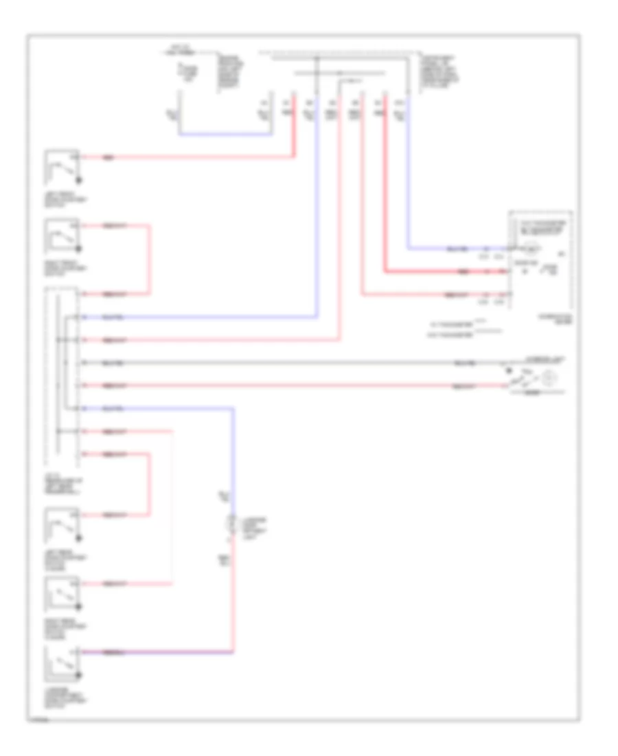
Courtesy Lamps Wiring Diagram for Toyota ECHO 2003
List of elements for Courtesy Lamps Wiring Diagram for Toyota ECHO 2003:
- C13
- C14
- Combination meter
- Dome fuse 15a
- Door
- Door ind
- Engine room r/b (on left side of engine compt)
- G12
- Hot at all times
- Instrument panel j/b (behind left side of dash, near base of "a" pillar)
- Interior light
- J/c 10 (rearward of left rear fenderwell)
- Left front door courtesy switch
- Left rear door courtesy switch (4 door)
- Luggage comp- artment light
- Luggage compartment door courtesy switch
- Off
- Red
- Right front door courtesy switch
- Right rear door courtesy switch (4 door)
- W/ tachometer
- W/o tachometer
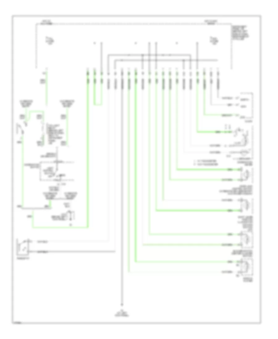
Instrument Illumination Wiring Diagram for Toyota ECHO 2003
List of elements for Instrument Illumination Wiring Diagram for Toyota ECHO 2003:
- Acc fuse 15a
- Acc+
- Blower switch (center cluster switch)
- C13
- C15
- Clock
- Combination meter
- Combination switch
- Door lock control switch (w/ remote keyless entry) (w/o power window)
- Earth -
- F10
- F11
- F12
- Head
- Hot at all times
- Hot in acc or on
- Id (at left kick panel)
- Ill+
- Illum
- Instrument panel j/b (behind left side of dash, near base of "a" pillar)
- J/c 5 (behind left kick panel)
- K12
- Lcd illum
- Light control switch
- Off
- Radio & player
- Rheostat
- Shift lever position illumination (o/d main switch) (a/t)
- Tail
- Tail fuse 10a
- Taillight relay (behind left side of dash, next to instrument panel j/b)
- W/ remote keyless entry
- W/ tachometer
- W/o remote keyless entry
- W/o tachometer
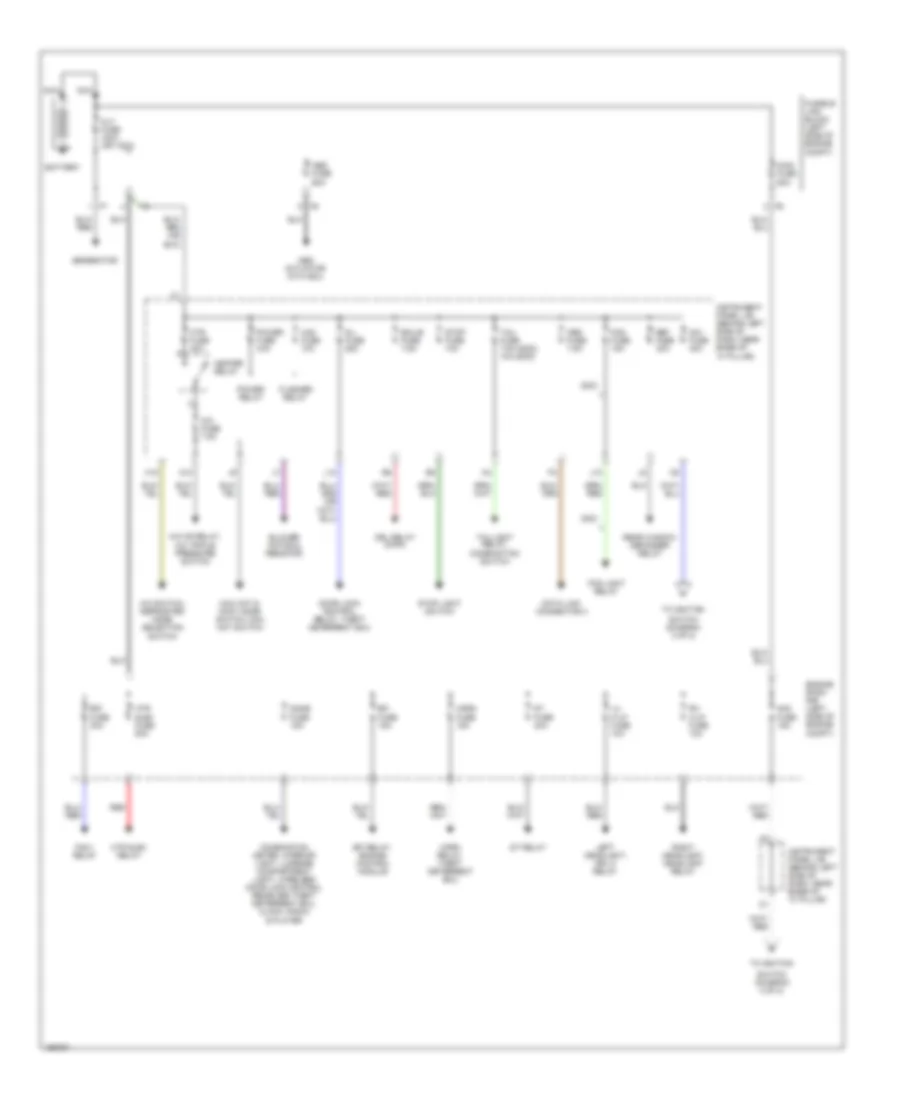
POWER DISTRIBUTION
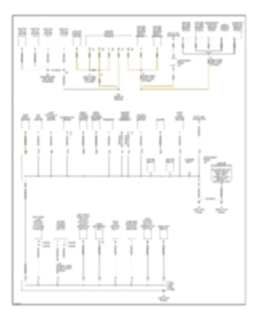
Power Distribution Wiring Diagram (1 of 2) for Toyota ECHO 2003
List of elements for Power Distribution Wiring Diagram (1 of 2) for Toyota ECHO 2003:
- A/c fuse 7.5a
- A/c mg relay, a/c triple pressure switch
- A/c switch, defroster mode selection switch
- A10
- Abs actuator with ecu
- Abs fuse 60a
- Alt fuse 100a (or 120a)
- Am1 fuse 40a
- Am2 fuse 15a
- Battery
- Blower motor & resistor
- Combination meter, interior light, luggage compartment light, wireless door lock control receiver, theft deterrent ecu, clock, radio & player
- D/l fuse 25a
- Data link connector 3
- Def fuse 30a
- Dome fuse 15a
- Door lock control relay, theft deterrent ecu
- Drl relay (main)
- Ecu-b fuse 7.5a
- Efi fuse 15a
- Efi relay, engine control module
- Engine room r/b (left side of engine compt)
- Fan 1 relay
- Flasher relay
- Fog fuse 15a
- Fog light relay
- Fusible link block (left side of engine compt)
- Generator
- H18
- Haz fuse 10a
- Heater relay
- Horn fuse 15a
- Horn relay, theft deterrent ecu
- Htr fuse 40a
- Htr sub1 fuse 50a
- Htr sub1 relay
- Instrument panel j/b (behind left side of dash, near base of "a" pillar)
- J10
- L10
- Left headlight, drl 5 relay
- Lh h-lp fuse 10a
- Main fuse 60a
- Max hot & foot mode switch, max hot switch
- Nca
- Obd fuse 7.5a
- Power fuse 30a
- Power relay
- Rdi fuse 30a
- Rear window defogger relay
- Red
- Rh h-lp fuse 10a
- Right headlight, headlight relay
- St fuse 30a
- St relay
- Stop fuse 10a
- Stop light switch
- Switch (diagram 2 of 2)
- Tail fuse 7.5a (2002) 10a (2003)
- Taillight relay, combination switch
- To ignition
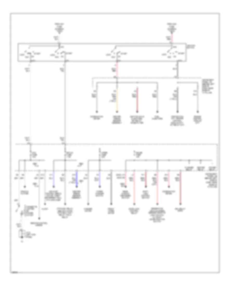
Power Distribution Wiring Diagram (2 of 2) for Toyota ECHO 2003
List of elements for Power Distribution Wiring Diagram (2 of 2) for Toyota ECHO 2003:
- (2002) j10
- (2003) r8
- Acc
- Acc fuse 15a
- Air inlet control servo motor, theft deterrent ecu, ptc amplifier
- Am1
- Am2
- Center airbag sensor assembly
- Cigarette lighter or power outlet
- Clock
- Combination meter
- D10
- Door lock control relay
- Drl relay (main)
- Ecu-ig fuse 7.5a
- Engine control module (a/t)
- Flasher relay
- From am1
- From am2
- Front wiper motor
- Fuel injectors
- Fuse (diagram 1 of 2) a
- Fuse (diagram 1 of 2) b
- G13
- Gauge fuse 10a
- Generator, vehicle speed sensor, back-up light switch, a/t shift lever position switch
- H11
- H15
- Heater relay
- Htr sub1 relay, abs actuator with ecu, fan 1 relay, fan 2 relay
- Ig1
- Ig2
- Ignition coils & ignitors, efi relay, noise filter
- Ignition switch
- Instrument panel j/b (behind left side of dash, near base of "a" pillar)
- J/c 5 (left kick panel)
- K12
- Lock
- P11
- Pnp switch (a/t), engine control module (m/t), st relay (m/t)
- Power relay
- Radio & player
- Rear window defogger switch
- Remote control mirror
- Shift lock control switch
- St2
- Start
- Washer motor
- Wiper fuse 20a
- Wiper/ washer switch
POWER DOOR LOCKS
Power Door Locks Wiring Diagram, with Keyless Entry for Toyota ECHO 2003
List of elements for Power Door Locks Wiring Diagram, with Keyless Entry for Toyota ECHO 2003:
- (behind left kick panel) junction connector 5
- (behind right kick panel) junction connector 9
- (behind upper left side of dash) wireless door lock control receiver
- (in body harness, below left "b" pillar) b3
- 2 door
- 4 door
- C14
- Combination meter
- D/l fuse 25a
- Detect
- Dome fuse 15a
- Door lock control relay (behind upper left side of dash, near instrument cluster)
- Door lock control switch lock (w/o power windows)
- Engine room r/b (on left side of engine compt)
- Exterior lights system
- Gauge fuse 10a
- Gnd
- Headlights system
- Horns system
- Hot at all times
- Hot in on or start
- Id (at left kick panel)
- Instrument panel j/b (behind left side of dash, near base of "a" pillar)
- J/c 12
- J/c 13 & 14
- J/c 5 (behind left kick panel)
- J13
- J14
- Junction connector 10 (rearward of left rear fenderwell)
- Junction connector 6 & 7 (behind upper center of dash, below instrument cluster)
- L10
- L13
- Left door lock control switch lock (power window master switch) (w/ power windows)
- Left front door courtesy switch
- Left front door lock motor, unlock detection switch & door key lock/ unlock switch
- Left rear door courtesy switch (4 door)
- Left rear door lock motor (4 door)
- Lock
- P16
- P19
- Prg
- Rda
- Red
- Right door lock control lock switch (w/ power windows)
- Right front door courtesy switch
- Right front door lock motor & door key lock/ unlock switch
- Right rear door courtesy switch (4 door)
- Right rear door lock motor (4 door)
- Unlk
- Unlock warning switch
- W/ tachometer
- W/o tachometer
Power Door Locks Wiring Diagram, without Keyless Entry for Toyota ECHO 2003
List of elements for Power Door Locks Wiring Diagram, without Keyless Entry for Toyota ECHO 2003:
- (4 door)
- (behind left kick panel) junction connector 5
- (behind right kick panel) junction connector 9
- (in body harness, below left "b" pillar) b3
- 13 & 14
- 2 door
- 4 door
- D/l fuse 25a
- Detect
- Door lock control relay (behind upper left side of dash, near instrument cluster)
- Door lock control switch lock (w/o power windows)
- Gauge fuse 10a
- Hot at all times
- Hot in on or start
- Instrument panel j/b (behind left side of dash, near base of "a" pillar)
- Instrument panel j/b (behind left side of dash, near base of ``a" pillar)
- J/c
- J/c 12
- J13
- J14
- Junction connector 6 & 7 (behind upper center of dash, below instrument cluster)
- L10
- Left door lock control switch lock (power window master switch) (w/ power windows)
- Left front door courtesy switch
- Left front door lock motor, unlock detection switch & door key lock/ unlock switch
- Left rear door lock motor
- Lock
- Red
- Right door lock control lock switch (w/ power windows)
- Right front door lock motor & door key lock/ unlock switch
- Right rear door lock motor
- Unlk
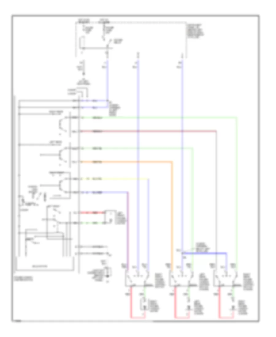
POWER MIRRORS
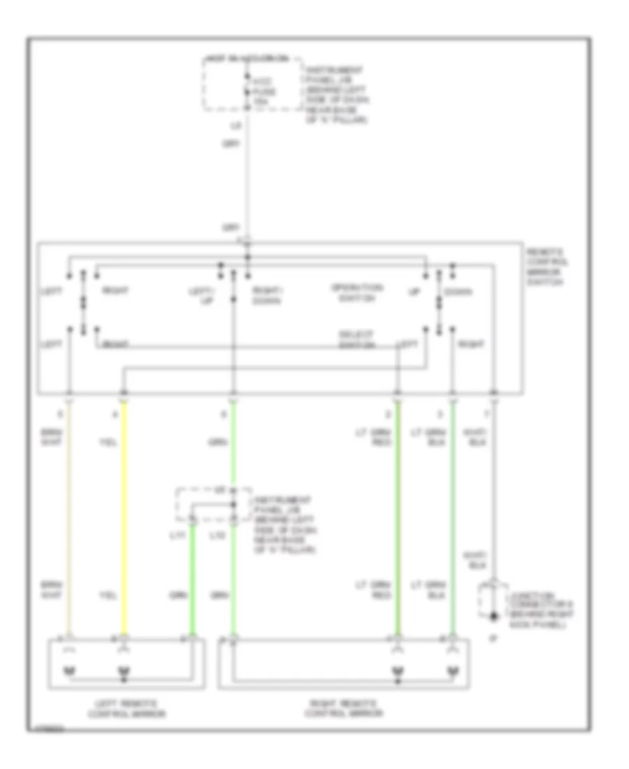
Power Mirrors Wiring Diagram for Toyota ECHO 2003
List of elements for Power Mirrors Wiring Diagram for Toyota ECHO 2003:
- Acc fuse 15a
- Down
- Hot in acc or on
- Instrument panel j/b (behind left side of dash, near base of "a" pillar)
- Junction connector 9 (behind right kick panel)
- L11
- L12
- Left
- Left remote control mirror
- Left/ up
- Operation switch
- Remote control mirror switch
- Right
- Right remote control mirror
- Right/ down
- Select switch
POWER WINDOWS
Power Windows Wiring Diagram for Toyota ECHO 2003
List of elements for Power Windows Wiring Diagram for Toyota ECHO 2003:
- (in body harness, below left "b" pillar)
- 2 door
- 4 door
- B1 (in body harness, in left front door)
- Down
- Gauge fuse 10a
- Hot at all times
- Hot in on or start
- Id (at left kick panel)
- Instrument panel j/b (behind left side of dash, near base of "a" pillar)
- Junction connector 5 (behind left kick panel)
- Left front
- Left front power window motor
- Left rear
- Left rear power window control switch (4 door)
- Left rear power window motor (4 door)
- Lock
- Normal
- Power fuse 30a
- Power relay
- Power window master switch
- Red
- Right front
- Right front power window control switch
- Right front power window motor
- Right rear
- Right rear power window control switch (4 door)
- Right rear power window motor (4 door)
- Rld
- Rlu
- Rrd
- Rru
- Solid state
- Window lock switch
RADIO
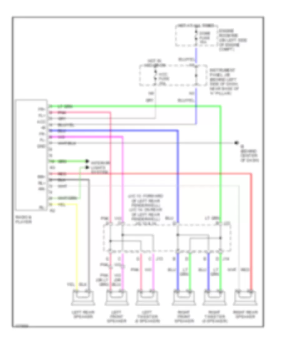
Radio Wiring Diagram for Toyota ECHO 2003
List of elements for Radio Wiring Diagram for Toyota ECHO 2003:
- (j/c 13: forward of left rear fenderwell) (j/c 14: on rear of left rear fenderwell) j/c 13 & 14
- Acc
- Acc fuse 15a
- Dome fuse 15a
- Engine room r/b (on left side of engine compt)
- Fl+
- Fl-
- Fr+
- Fr-
- Gnd
- Hot at all times
- Hot in acc or on
- Ie (behind center of dash)
- Instrument panel j/b (behind left side of dash, near base of "a" pillar)
- Interior lights system
- J13
- J14
- Left front speaker
- Left rear speaker
- Left tweeter (6 speaker)
- Pnk
- Pnk g
- Radio & player
- Red
- Right front speaker
- Right rear speaker
- Right tweeter (6 speaker)
- Rl+
- Rl-
- Rr+
- Rr-
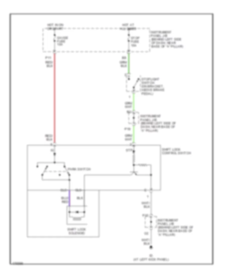
SHIFT INTERLOCK
Shift Interlock Wiring Diagram for Toyota ECHO 2003
List of elements for Shift Interlock Wiring Diagram for Toyota ECHO 2003:
- Gauge fuse 10a
- Hot at all times
- Hot in on or start
- Id (at left kick panel)
- Instrument panel j/b (behind left side of dash, near base of "a" pillar)
- P11
- P15
- P18
- Park switch
- Shift lock control switch
- Shift lock solenoid
- Sls+
- Sls-
- Stop fuse 10a
- Stoplight switch (on bracket, above brake pedal)
- Stp
STARTING/CHARGING
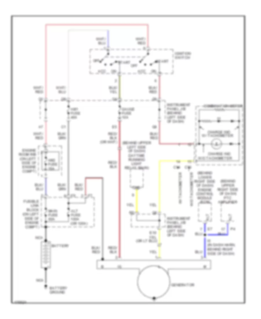
Charging Wiring Diagram for Toyota ECHO 2003
List of elements for Charging Wiring Diagram for Toyota ECHO 2003:
- (behind lower right side of dash) engine control module (ecm)
- (behind upper left side of dash)
- (behind upper right side of dash) ptc amplifier
- Acc
- Alt
- Alt fuse 100a (or 120a)
- Am1 fuse 40a
- Am2 fuse 15a
- Battery
- Battery ground
- C13
- C14
- Charge ind
- Chg-
- Combination meter
- Daytime running light relay (main)
- E10
- Engine room r/b (on left side of engine compt)
- Fusible link block (on left side of engine compt)
- Gauge fuse 10a
- Generator
- I5 (in dash harn, behind right side of dash)
- Ignition switch
- Instrument panel j/b (behind left side of dash)
- Main fuse 60a
- Nca
- Off
- Start
- W/ tachometer
- W/o tachometer
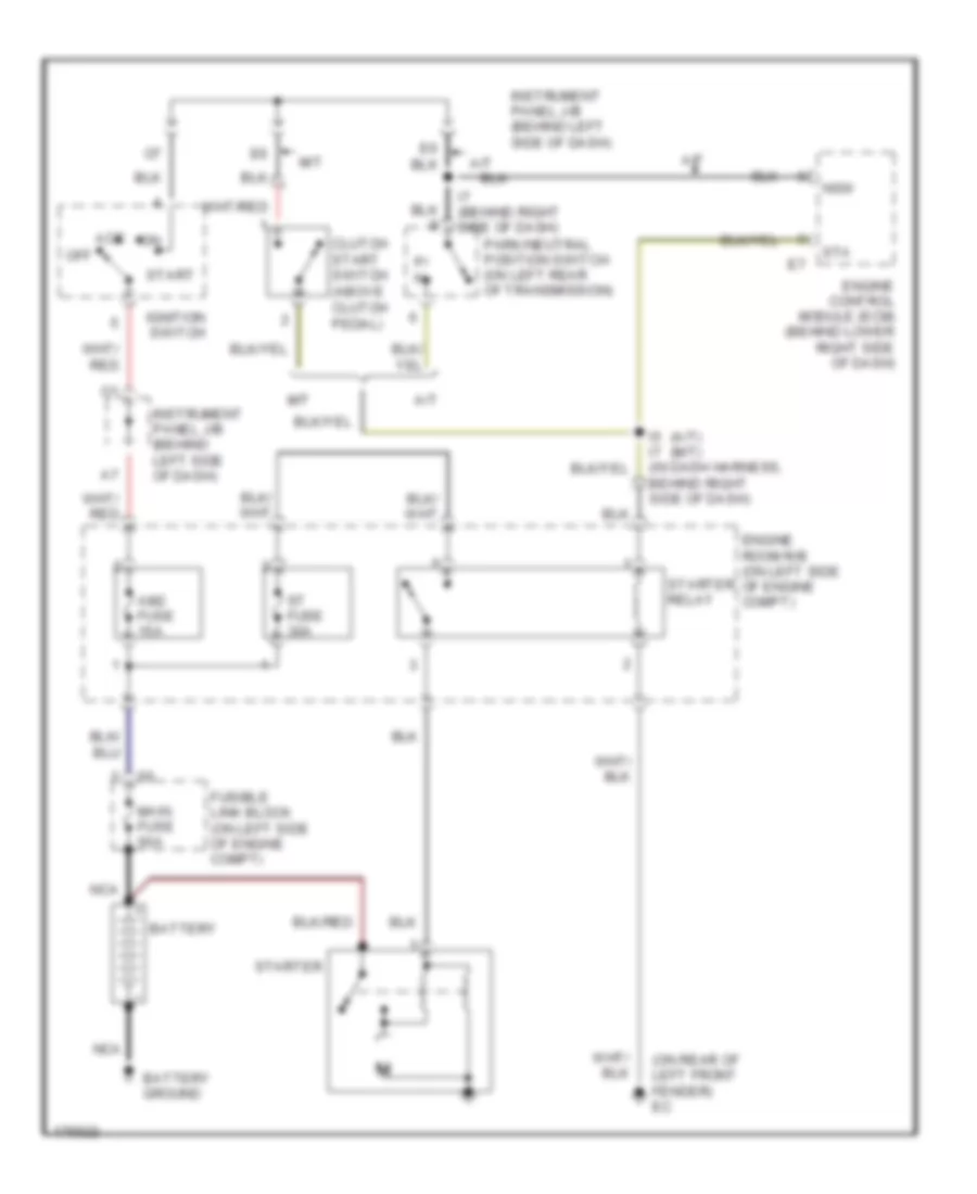
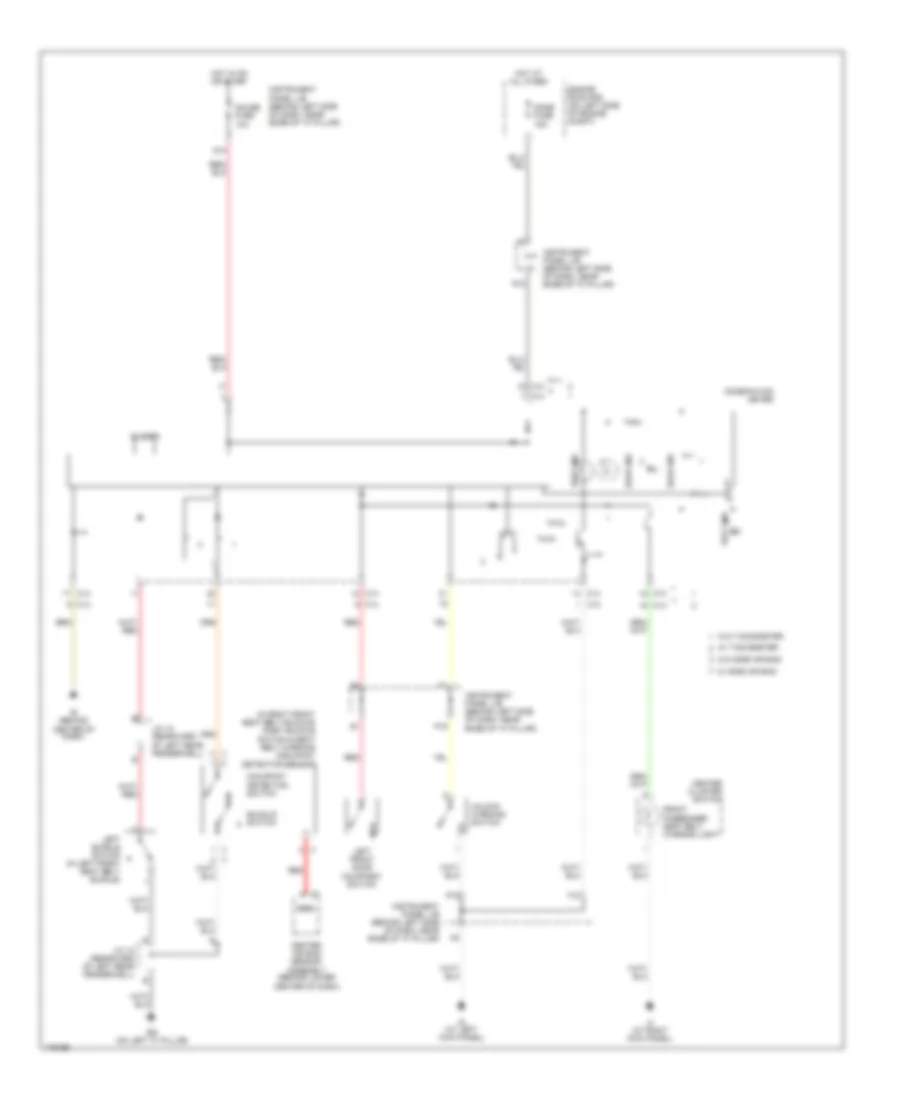
Starting Wiring Diagram for Toyota ECHO 2003
List of elements for Starting Wiring Diagram for Toyota ECHO 2003:
- (a/t) (m/t)
- (on rear of left front fender) ec
- A/t
- Acc
- Am2 fuse 15a
- Battery
- Battery ground
- Clutch start switch (above clutch pedal)
- Engine control module (ecm) (behind lower right side of dash)
- Engine room r/b (on left side of engine compt)
- Fusible link block (on left side of engine compt)
- I5 i7 (in dash harness, behind right side of dash)
- I7 (behind right side of dash)
- Ignition switch
- Instrument panel j/b (behind left side of dash)
- M/t
- Main fuse 60a
- Nca
- Nsw
- Off
- P/ n
- Park/neutral position switch (on left rear of transmission)
- St fuse 30a
- Sta
- Start
- Starter
- Starter relay
SUPPLEMENTAL RESTRAINTS
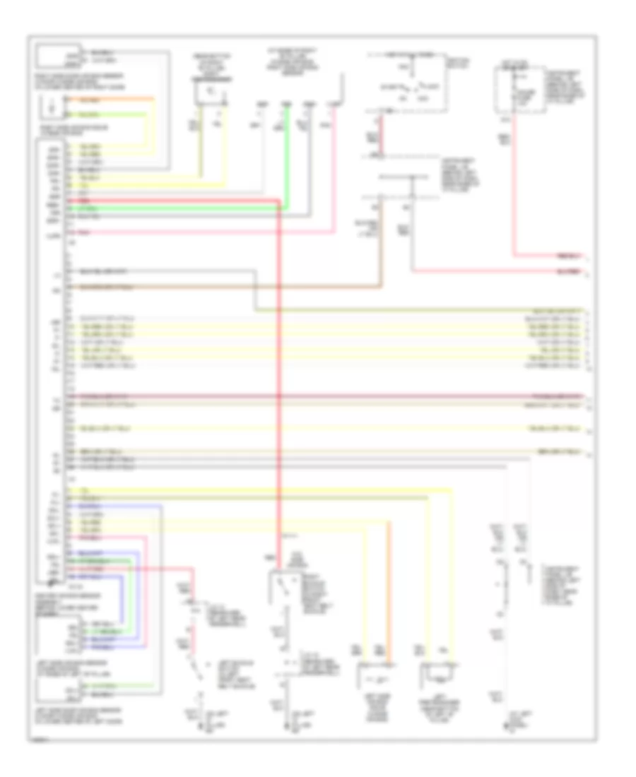
Supplemental Restraints Wiring Diagram (1 of 2) for Toyota ECHO 2003
List of elements for Supplemental Restraints Wiring Diagram (1 of 2) for Toyota ECHO 2003:
- (at base of right "b" pillar) (w/side air bag) right side air bag sensor
- (at left kick panel) id
- (near bottom of right "b" pillar) right pretensioner
- (on left "c" pillar) bg
- +sl
- +sr
- -sl
- -sr
- Acc
- Am2
- C3 (a)
- Center air bag sensor assembly (behind lower center of dash)
- Dml+
- Dml-
- Dmr+
- Dmr-
- Esl
- Esr
- Fsl
- Fsr
- G13
- Gauge fuse 10a
- Hot at all times
- Hot in on or start
- Ig2
- Ignition switch
- Instrument panel j/b (behind left side of dash, near base of "a" pillar)
- J/c 10 (rearward of left rear fenderwell)
- J/c 15 (rearward of left rear fenderwell)
- Lbe+
- Left buckle switch (in left front seat belt buckle)
- Left pretensioner (near bottom of left "b" pillar)
- Left side air bag sensor (w/side air bag) (at base of left "b" pillar)
- Left side air bag squib (w/side air bag)
- Left side door air bag sensor (2 door w/side air bag) (in lower center of left door)
- Lock
- Pl+
- Pl-
- Pnk
- Pr+
- Pr-
- Rbe+
- Red
- Right buckle switch (in right front seat belt buckle)
- Right side air bag squib (w/side air bag)
- Right side door air bag sensor (2 door w/side air bag) (in lower center of right door)
- Sfl+
- Sfl-
- Sfr+
- Sfr-
- Sil
- Ssl+
- Ssr+
- Start
- Vupl
- Vupr
- W/o side air bag
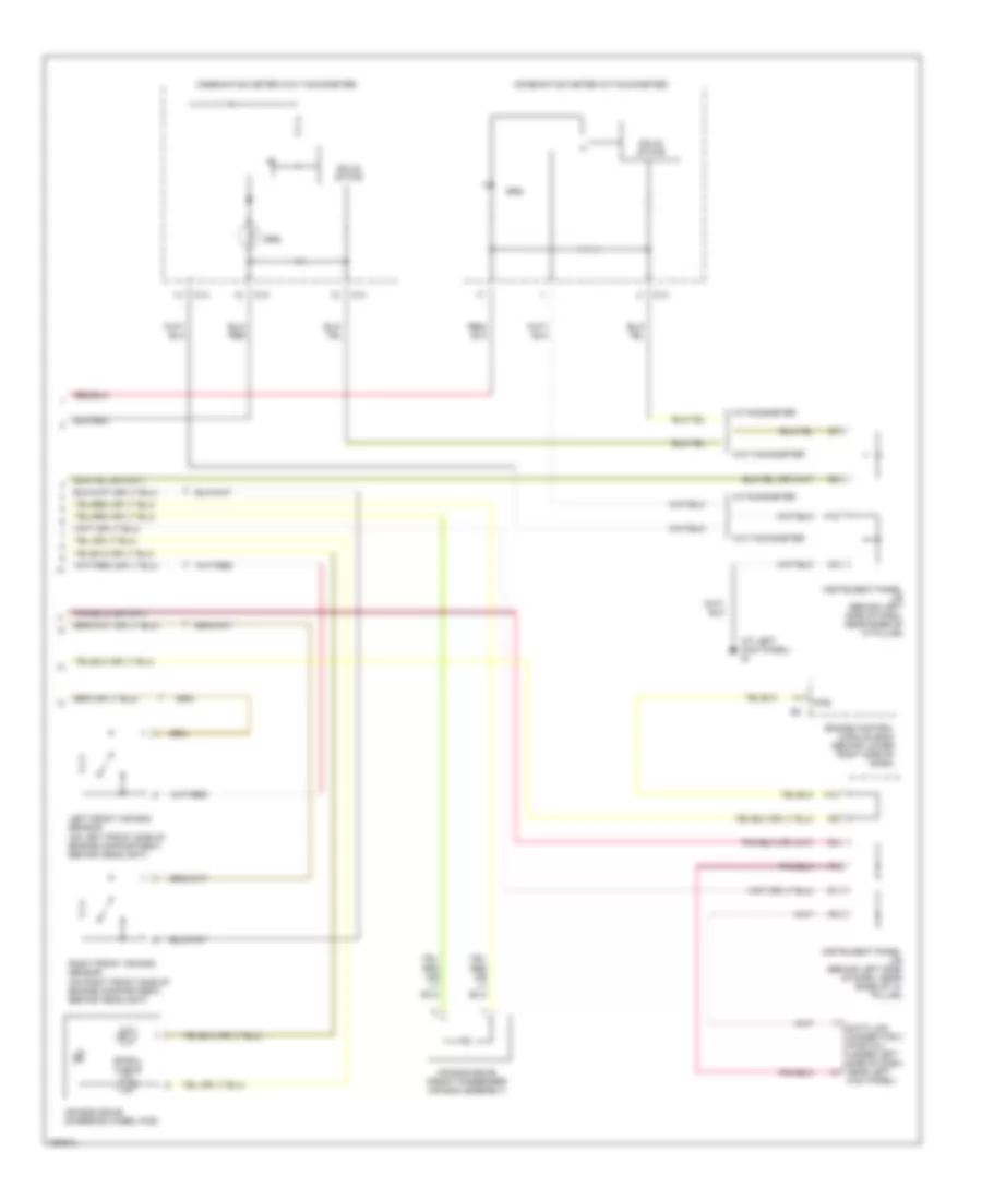
Supplemental Restraints Wiring Diagram (2 of 2) for Toyota ECHO 2003
List of elements for Supplemental Restraints Wiring Diagram (2 of 2) for Toyota ECHO 2003:
- (at left kick panel) id
- Air bag squib (front passenger air bag assembly)
- Air bag squib (steering wheel pad)
- C13
- C14
- Combination meter (w/o tachometer)
- Combination meter (w/tachometer)
- Data link connector 3 (partial) (under left side of dash, near left
- Engine control module (ecm) (behind lower right side of dash)
- F/ps
- F12
- H10
- Instrument panel j/b (behind left side of dash, near base of "a" pillar)
- Kick panel)
- Left front air bag sensor (on left front side of engine compartment, behind headlight)
- Right front air bag sensor (on right front side of engine compartment, behind headlight)
- Solid state
- Spiral cable
- Srs
- W/o tachometer
- W/tachometer
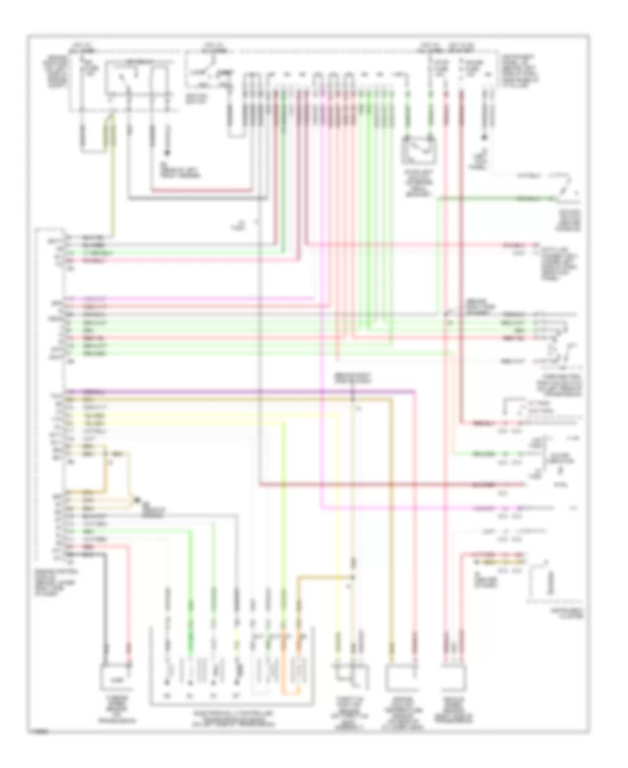
TRANSMISSION
A/T Wiring Diagram for Toyota ECHO 2003
List of elements for A/T Wiring Diagram for Toyota ECHO 2003:
- (behind right side of dash)
- A11
- Acc
- Batt
- C13
- C14
- Data link connector 3 (under left side of dash, near kick panel)
- E01
- E02
- E03
- Eb (rear of engine)
- Ec (rear of left front fender)
- Efi fuse 15a
- Efi relay
- Electronically controlled transmission solenoid (on left side of transmission)
- Engine control module (behind lower right side of dash)
- Engine coolant temperature sensor (on rear of cylinder head)
- Engine room r/b (on left side of engine compt)
- G13
- Gauge fuse 10a
- H12
- H13
- H14
- H16
- Hot at all times
- Hot in on or start
- Id (left kick panel)
- Ie (center of dash)
- Ignition switch
- Instrument cluster
- Instrument panel j/b (behind left side of dash, near base of "a" pillar)
- Lock
- Nt+
- Nt-
- O/d main switch (center console)
- O/d off indicator
- Odlp
- Odms
- Oil
- P13
- Park/neutral position switch (on left rear of transmission)
- Red
- Sil
- Slt+
- Slt-
- Spd
- Speedo
- Start
- Stop fuse 10a
- Stoplight switch (on brake pedal bracket)
- Stp
- Throttle position sensor (on throttle body assembly)
- Thw
- Turbine speed sensor (on transmission)
- Vehicle speed sensor (right side of transmission)
- Vta
- W/ tach
- W/o tach
WARNING SYSTEMS
Warning Systems Wiring Diagram for Toyota ECHO 2003
List of elements for Warning Systems Wiring Diagram for Toyota ECHO 2003:
- (in right front seat belt buckle) right buckle switch & seat belt warning occupant detection sensor
- Belt ind
- Bg (on left "c" pillar)
- Buckle switch
- Buzzer
- C13
- C14
- Center air bag sensor assembly (behind lower center of dash)
- Center cluster switch
- Combination meter
- Dome fuse 15a
- Door ind
- Engine room r/b (on left side of engine compt)
- F12
- Front passenger seat belt warning light
- G12
- G13
- Gauge fuse 10a
- Hot at all times
- Hot in on or start
- Id (at left kick panel)
- Ie (behind center of dash)
- If (at right kick panel)
- Instrument panel j/b (behind left side of dash, near base of "a" pillar)
- J/c 10 (rearward of left rear fenderwell)
- J/c 15 (rearward of left rear fenderwell)
- Left buckle switch (in left front seat belt buckle)
- Left front door courtesy switch
- Occupant detection switch
- P16
- P19
- Rbe+
- Red
- Unlock warning switch
- W/ side air bag
- W/ tachometer
- W/o side air bag
- W/o tachometer
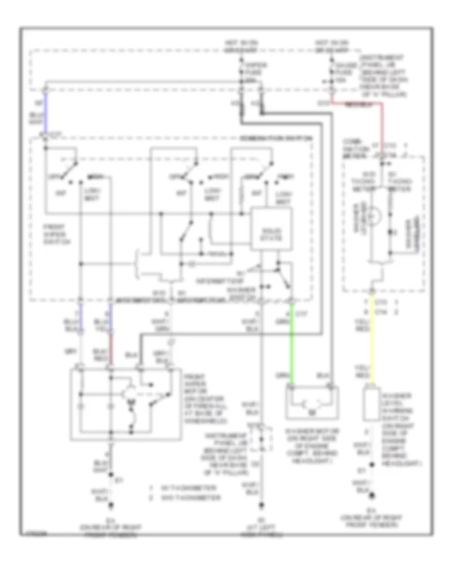
WIPER/WASHER
Wiper/Washer Wiring Diagram for Toyota ECHO 2003
List of elements for Wiper/Washer Wiring Diagram for Toyota ECHO 2003:
- C13
- C14
- C17
- Comb- ination meter
- Combination switch
- Ea (on rear of right front fender)
- Front wiper motor (on center of firewall, at base of windshield)
- Front wiper switch
- G13
- Gauge fuse 10a
- High
- Hot in on or start
- Id (at left kick panel)
- Instrument panel j/b (behind left side of dash, near base of "a" pillar)
- Int
- Low/ mist
- N11
- Off
- Solid state
- W/ intermittent
- W/ tacho- meter
- W/ tachometer
- W/o intermittent
- W/o tacho- meter
- W/o tachometer
- Washer level ind
- Washer level warning switch (on right side of engine compt, behind headlight)
- Washer motor (on right side of engine compt, behind headlight)
- Washer switch
- Wiper fuse 20a

 Čeština
 Dansk
Dansk Deutsch
 English
 English
 Español
 Suomi
Suomi Français
 Français
 עברית
עברית Hrvatski
 Magyar
 Italiano
 日本語
日本語 한국어
한국어 Nederlands
 Polski
 Português
 Português
 Română
 Русский
 Slovenčina
 Slovenščina
 Svenska
 Türkçe
 中文 (中国)