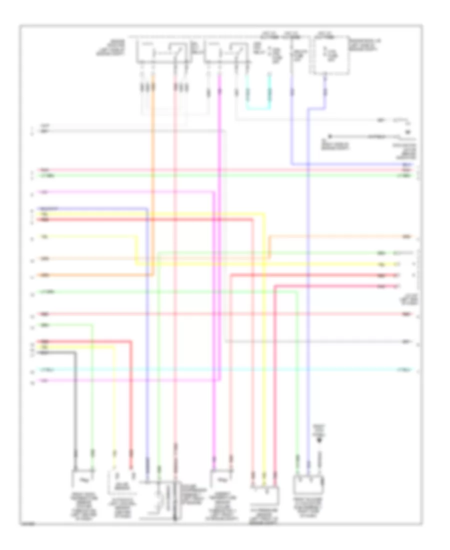
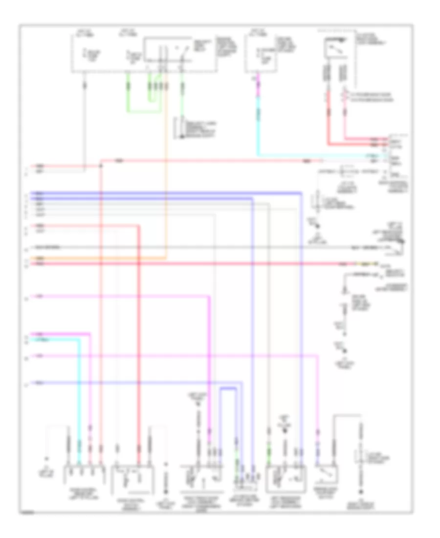
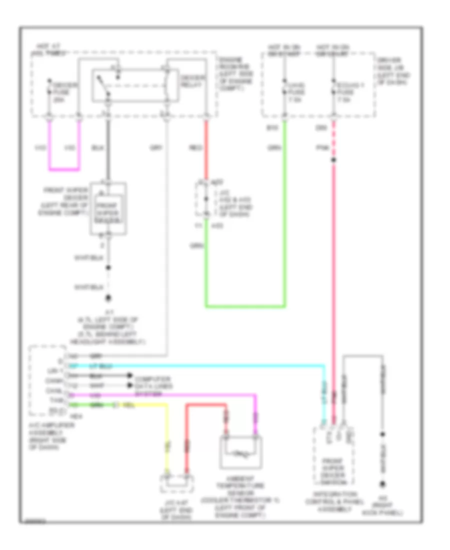
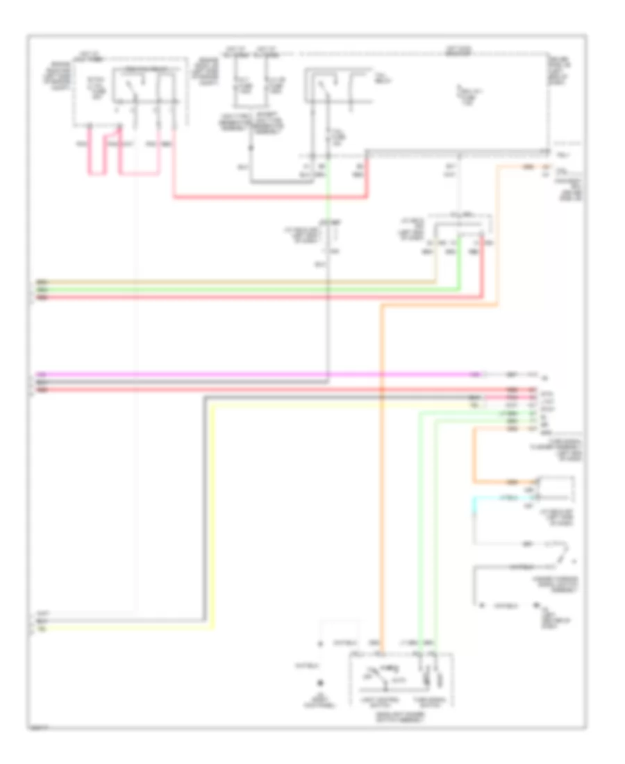
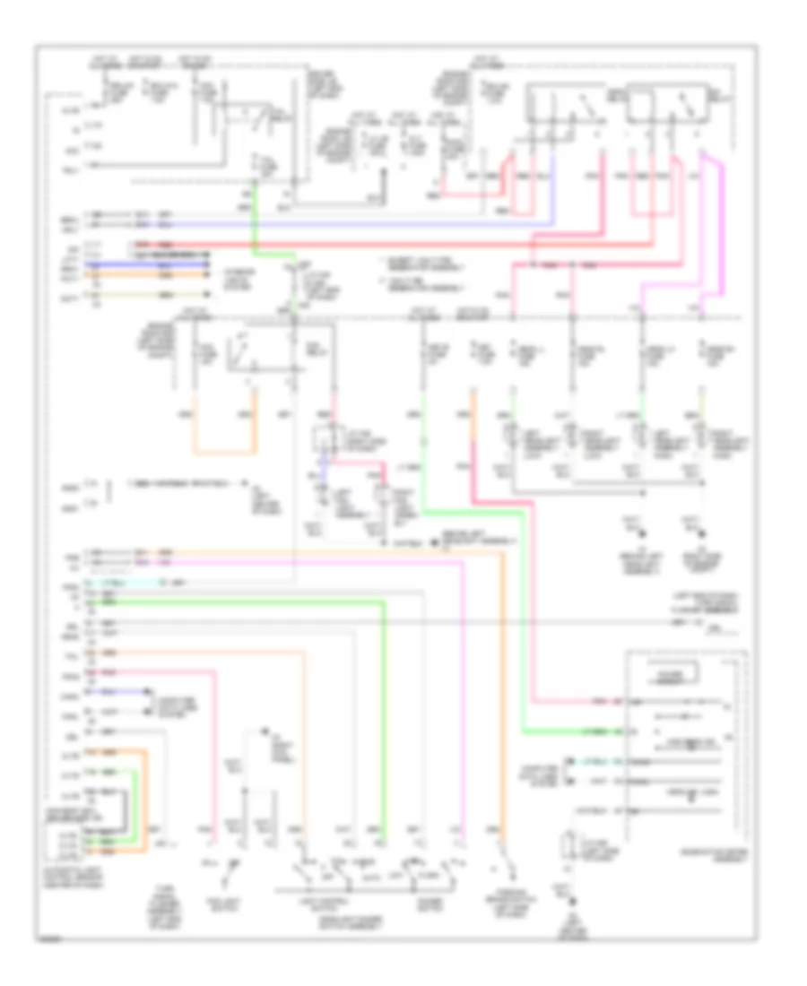
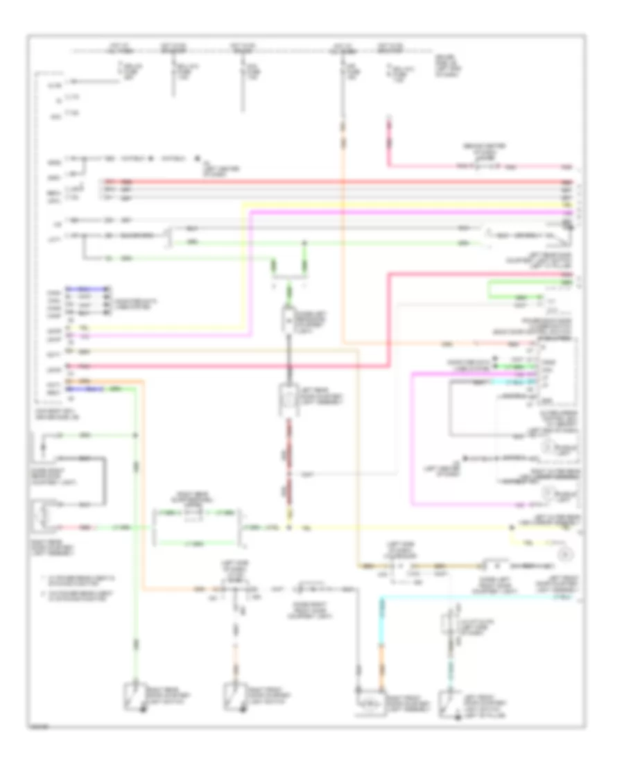
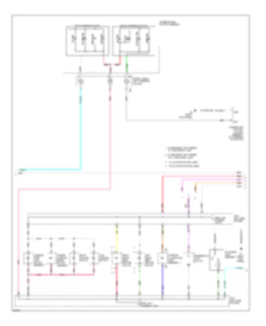
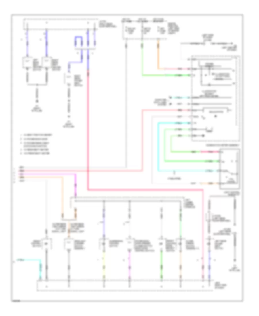
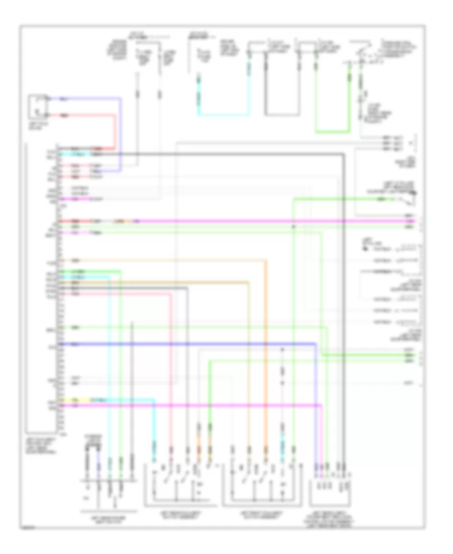
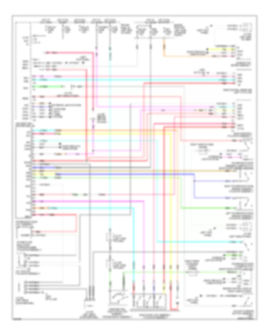
AIR CONDITIONING
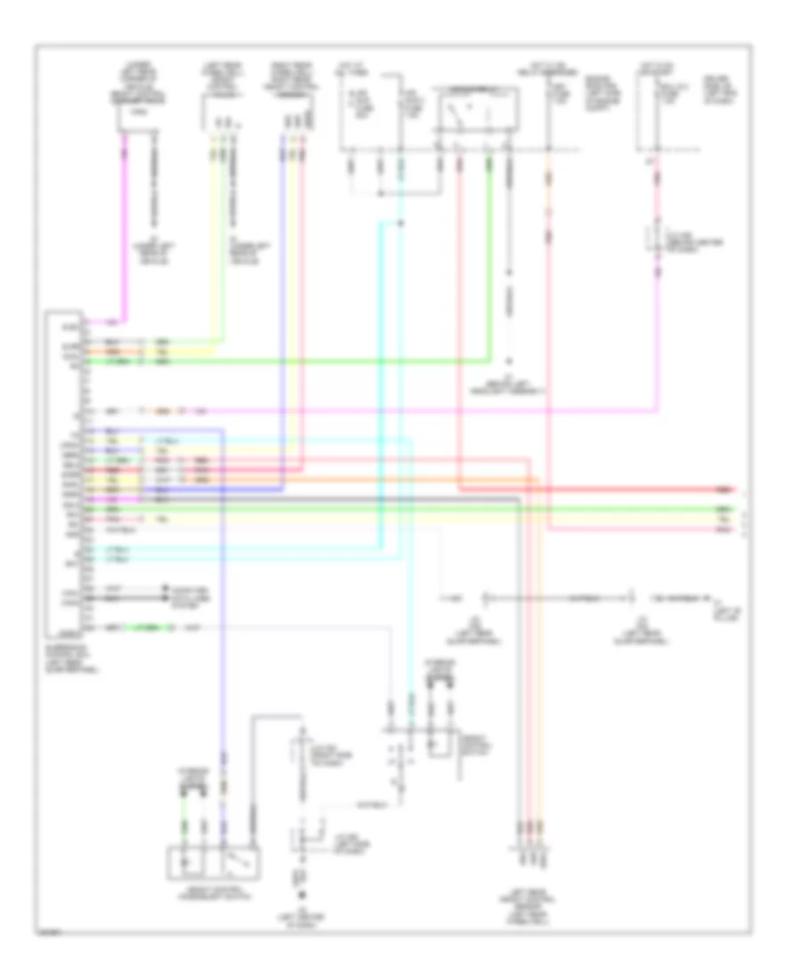
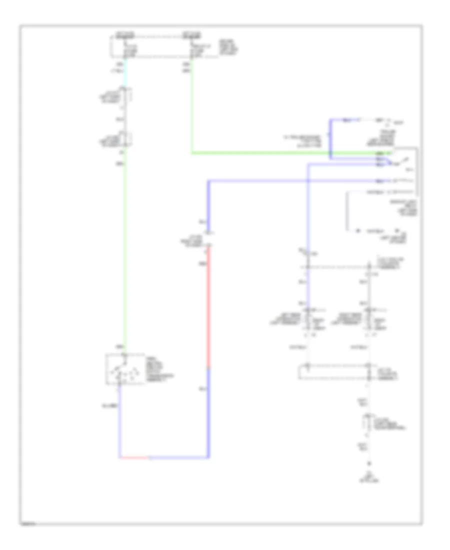
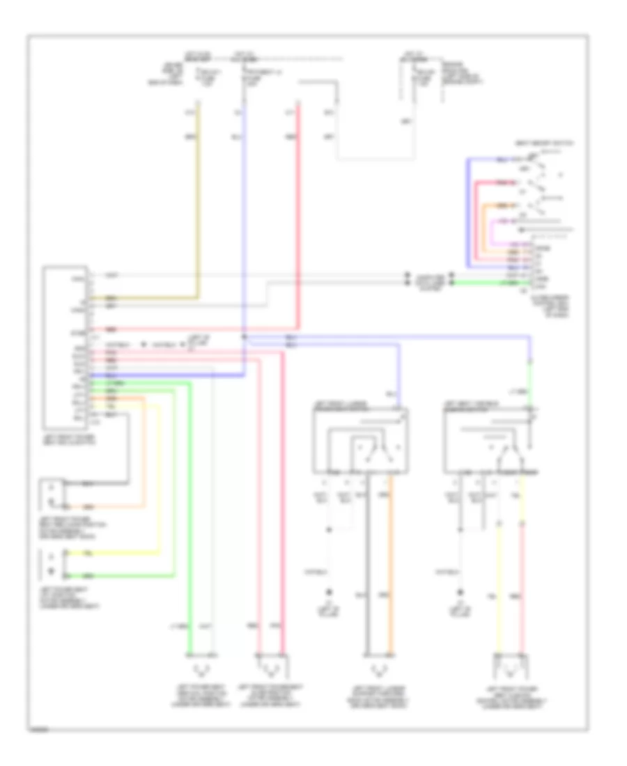
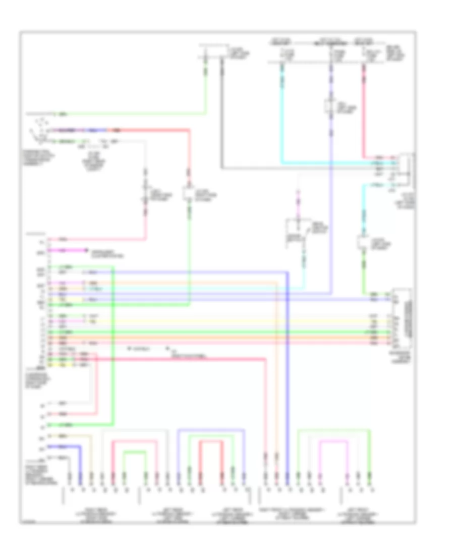
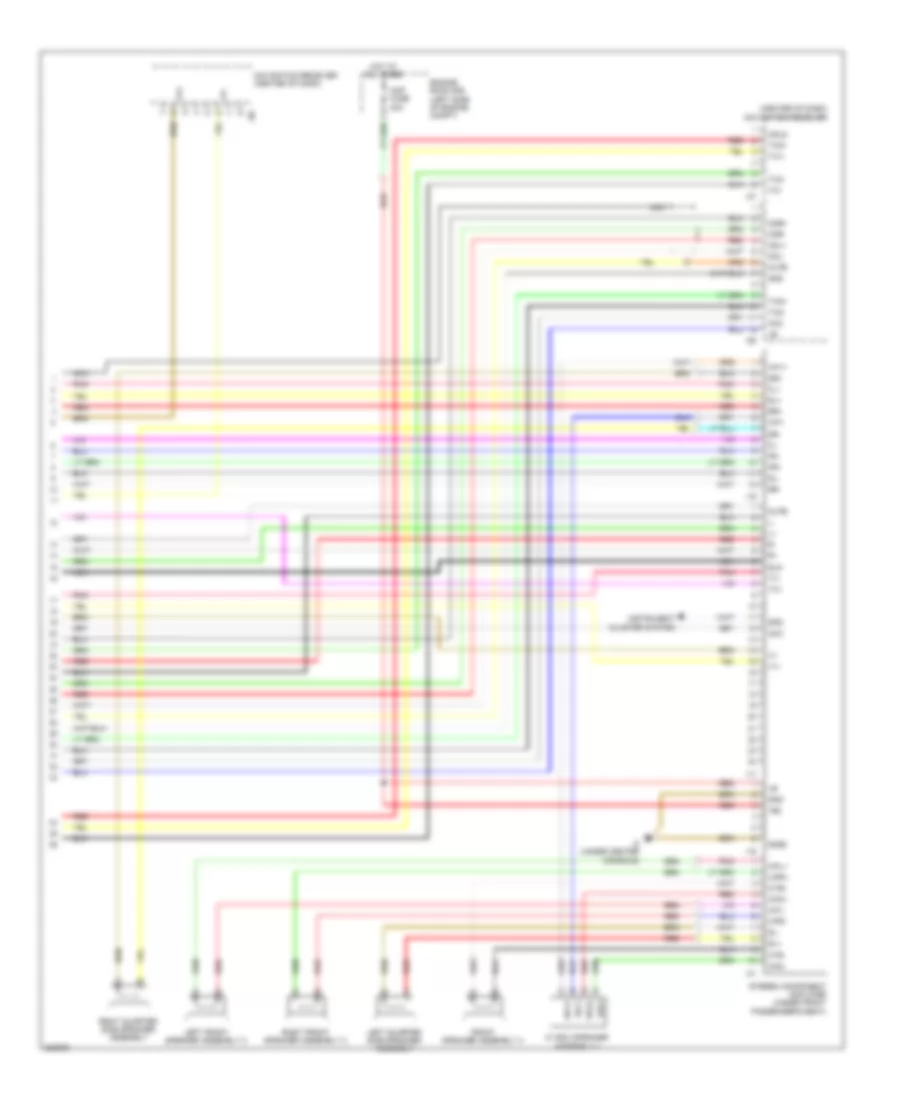
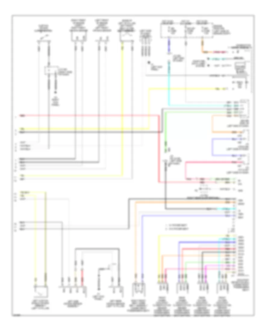
Automatic A/C Wiring Diagram (1 of 3) for Toyota Sequoia Limited 2010
 https://portal-diagnostov.com/license.html
Automotive Electricians Portal FZCO
Automotive Electricians Portal FZCO
https://portal-diagnostov.com/license.html
https://portal-diagnostov.com/license.html
Automotive Electricians Portal FZCO
Automotive Electricians Portal FZCO
List of elements for Automatic A/C Wiring Diagram (1 of 3) for Toyota Sequoia Limited 2010:
- (left side of dash) j/c h77
- (left side of dash) j/c h80
- (right kick panel) h3
- A/c amplifier assembly (right side of dash)
- A/c evaporator temperature sensor
- A/c fuse 7.5a
- A/c ig fuse 10a
- Ac1
- Act
- B bus
- Blw
- Bus
- Bus g
- Canh
- Canl
- Cfn+
- Computer data lines system
- Connector housing color (black)
- Connector housing color (green)
- Connector housing color (natural)
- Connector housing color (red)
- D55
- D56
- D58
- D59
- Damper servo motor (air inlet)
- Damper servo motor (air mix driver side)
- Damper servo motor (air mix front passenger side)
- Damper servo motor (air vent mode)
- Damper servo motor (cool air bypass)
- Defogger system
- Driver side j/b (left end of dash)
- Ecu-ig 1 fuse 7.5a
- Front a/c blower assembly
- Gnd
- H24
- H3 (right kick panel)
- Hot at all times
- Hot in on or start
- Ig+
- Lh ig fuse 7.5a
- Lin1
- Lock
- Mgc
- Mhtr
- Pnk
- Pre
- Rdef
- Rear a/c control assembly
- Red
- Rlin
- S5-3
- Sg-1
- Sg-2
- Sga
- Tam
- Tea
- Tsd
- Tsp
- Z13
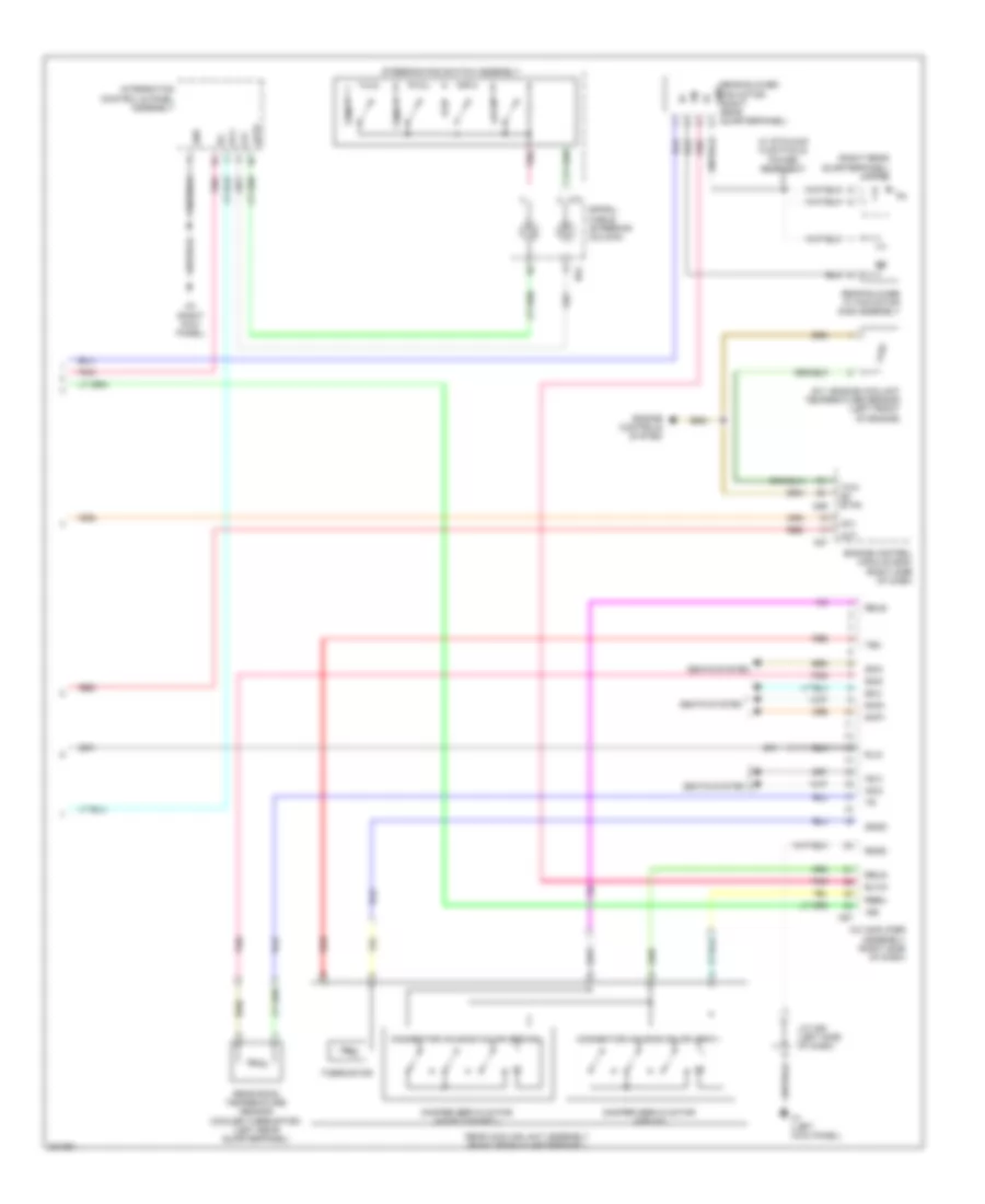
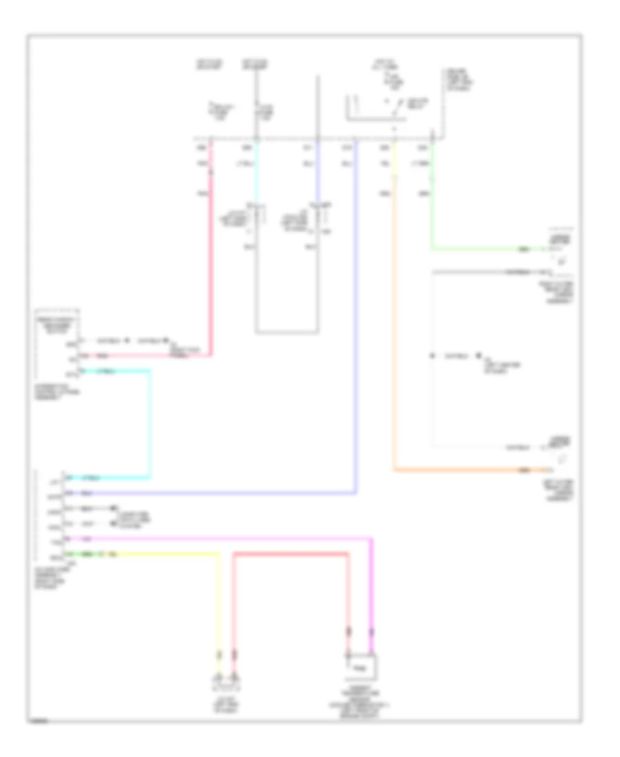
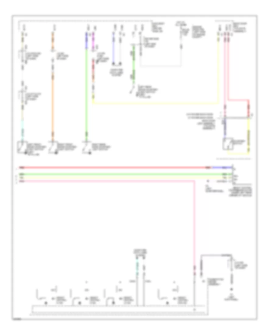
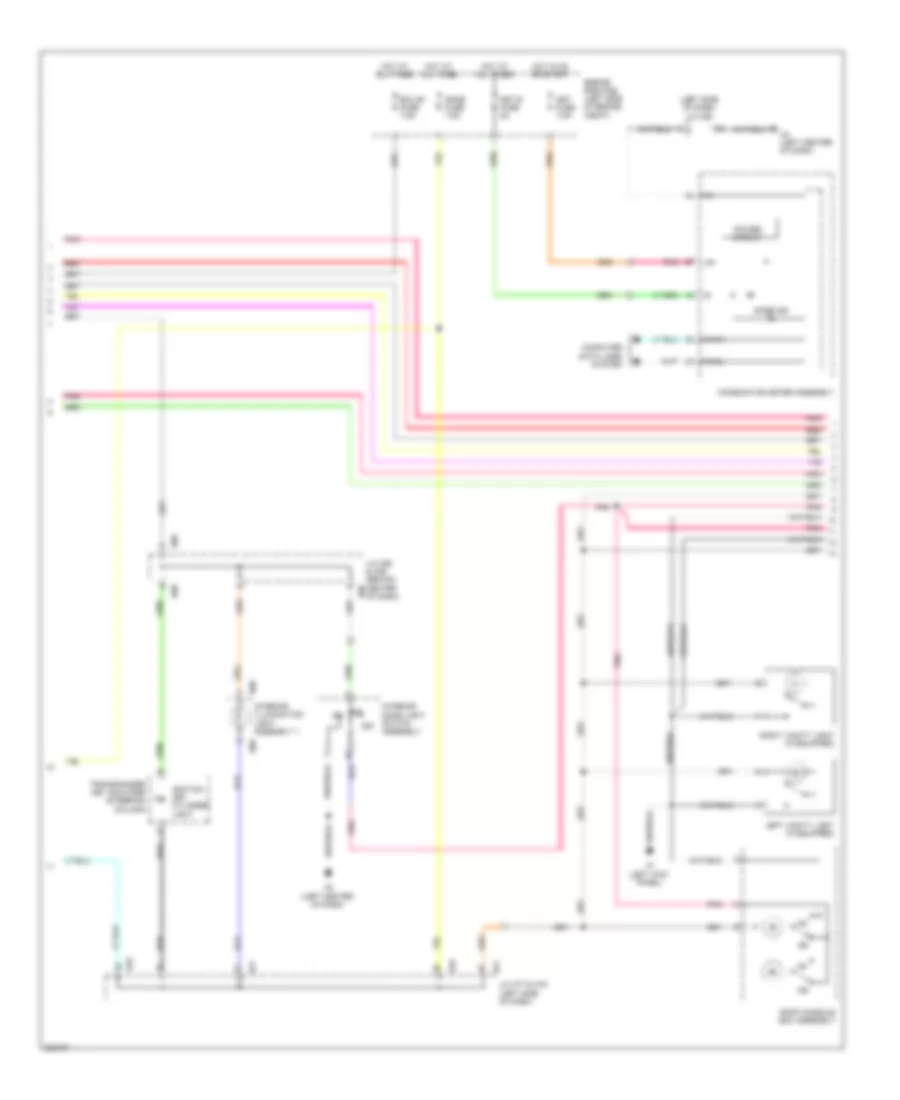
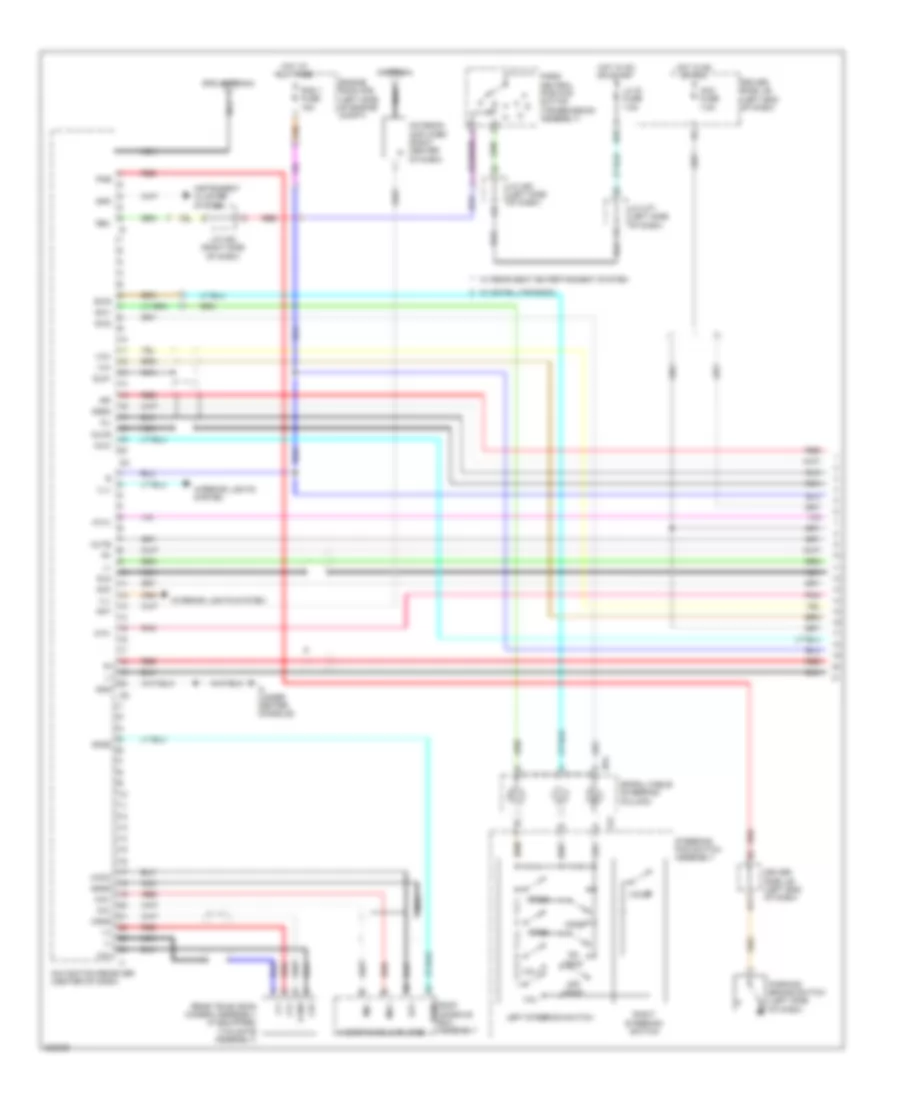
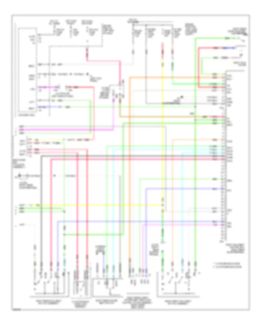
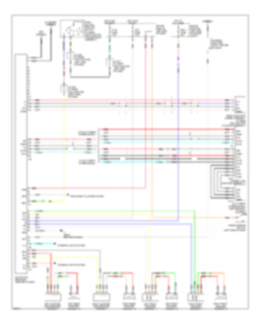
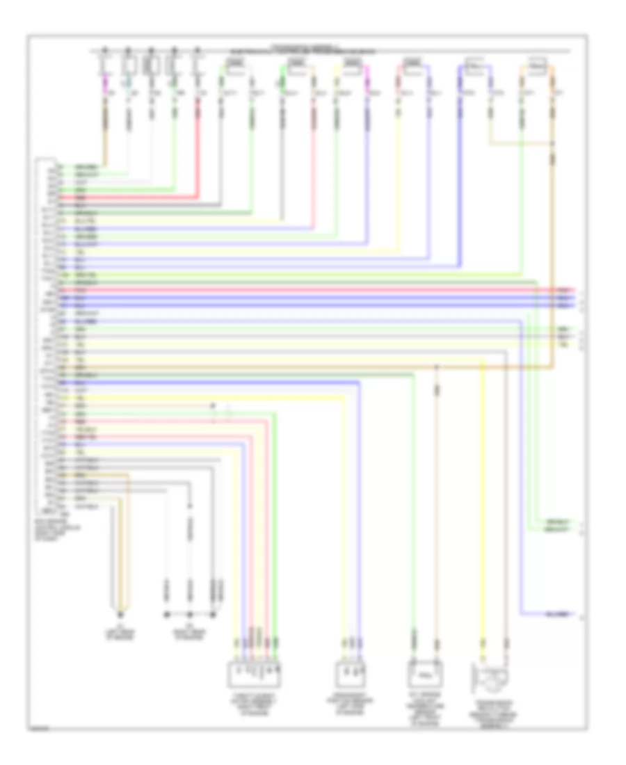
Automatic A/C Wiring Diagram (2 of 3) for Toyota Sequoia Limited 2010
List of elements for Automatic A/C Wiring Diagram (2 of 3) for Toyota Sequoia Limited 2010:
- (cooler thermistor 1) (left front of engine compt)
- (right kick panel) h3
- A/c pressure sensor (left front of engine compt)
- A3 (right side of engine compt)
- Ambient temperature sensor
- Automatic light control sensor (center of dash)
- Cds fan fuse 25a
- Cds fan relay
- Cooler compressor assembly (left front of engine)
- Cooling fan motor (behind radiator)
- Engine room j/b (left side of engine compt)
- Engine room r/b (left side of engine compt)
- Front blower w/ fan motor sub-assembly (right side of dash)
- Front room temperature sensor (cooler thermistor) (left center of dash)
- Gnd
- Hot at all times
- Htr fuse 50a
- J/c a47 (left end of dash)
- Lock sensor
- Magnetic clutch
- Mg clt relay
- Pnk
- Red
- Rr htr fuse 40a
- Solar sensor
- Tsl
- Tsr
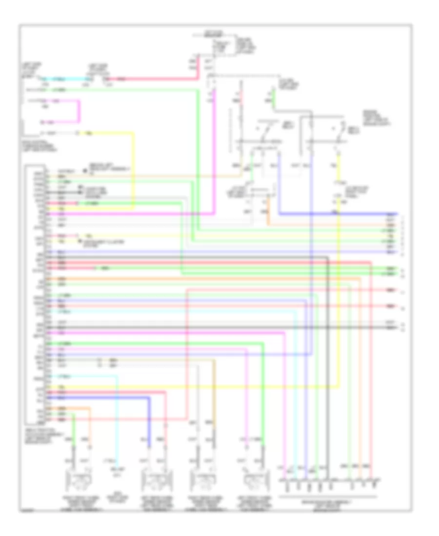
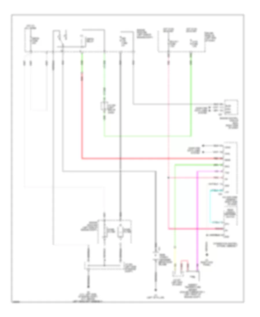
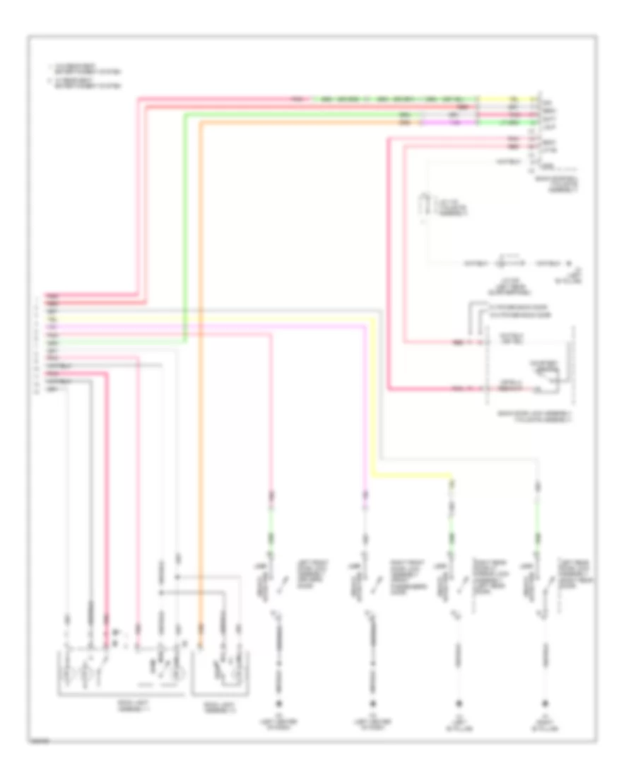
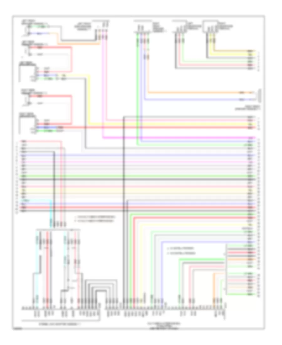
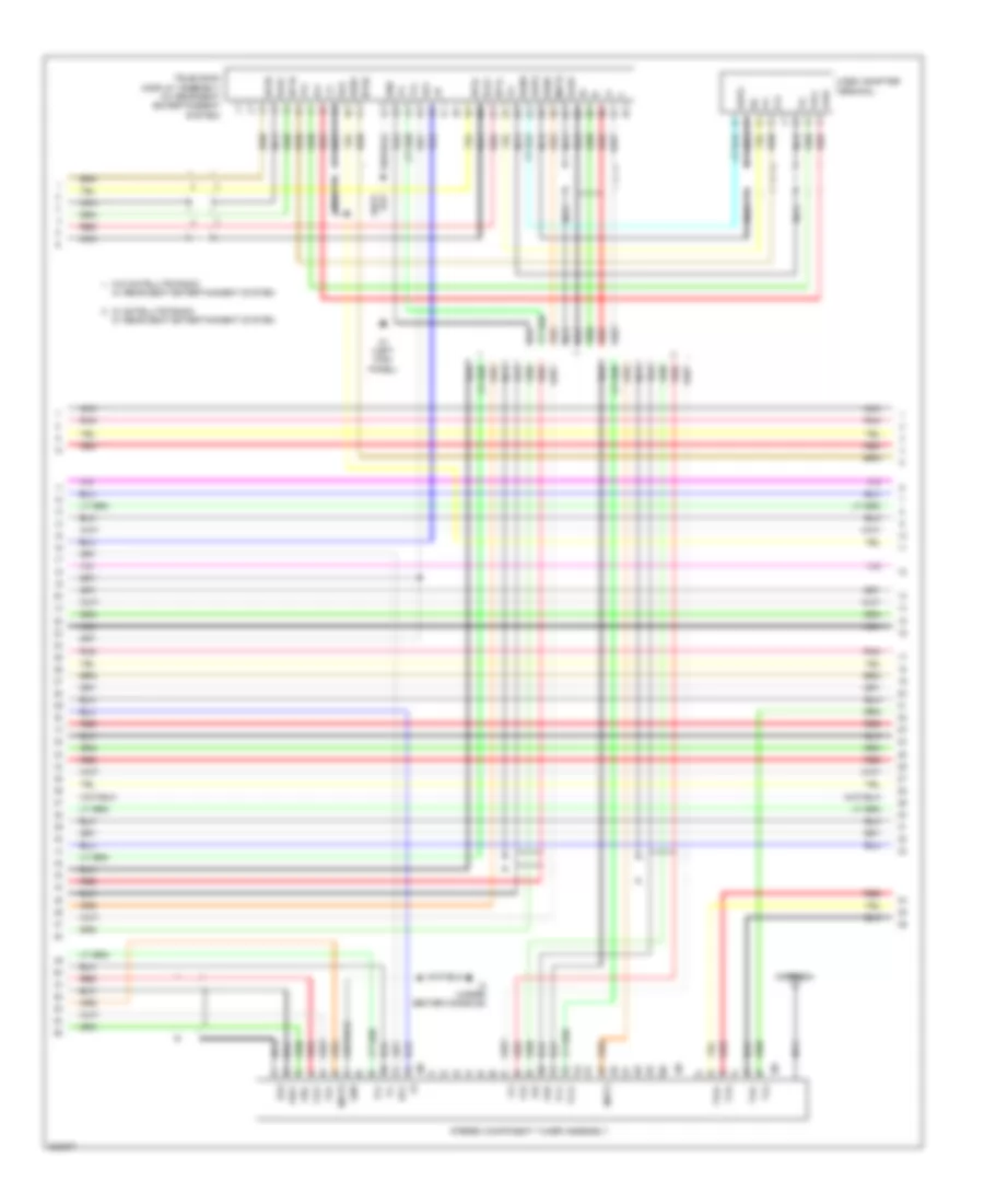
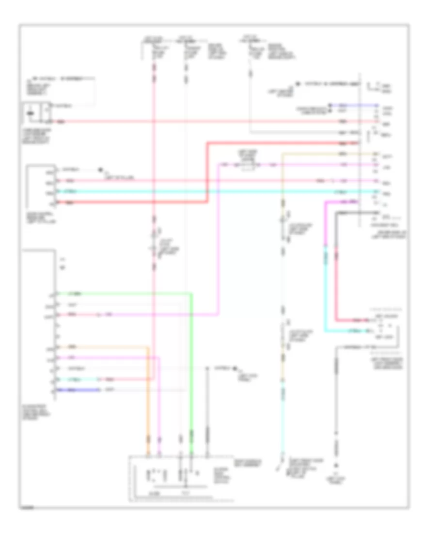
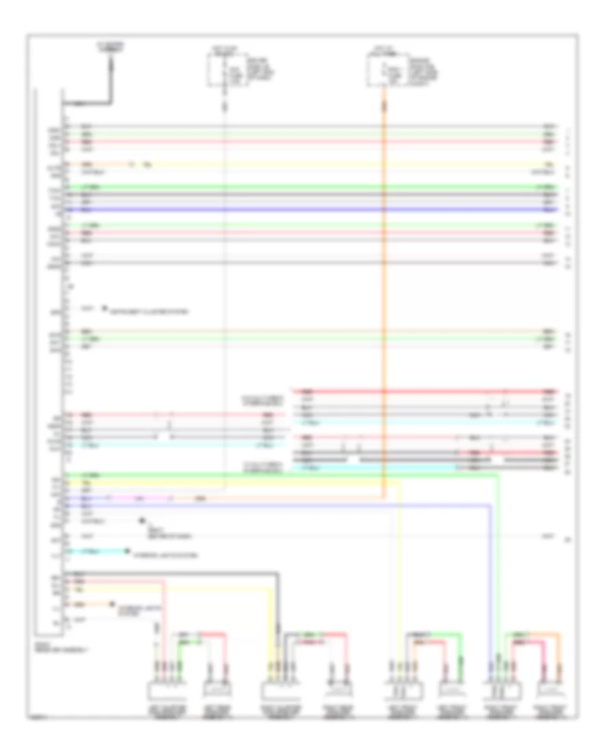
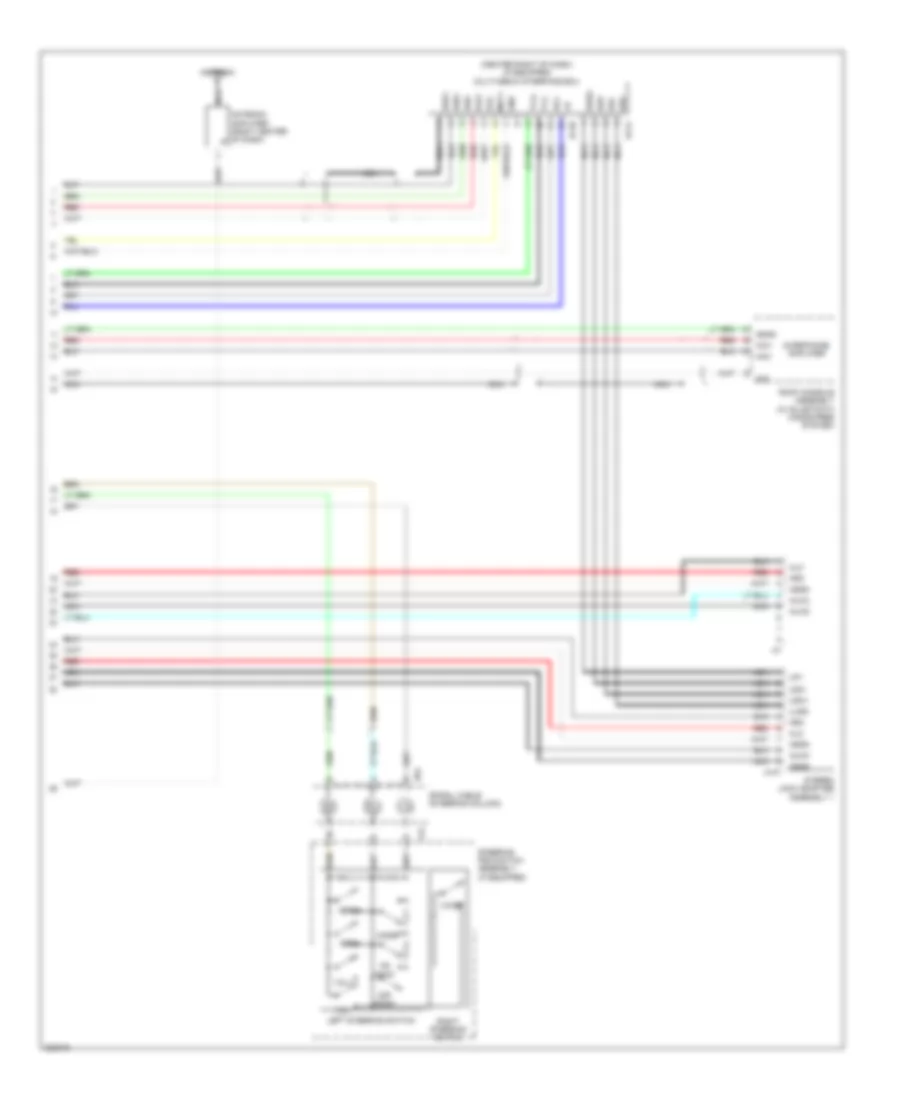
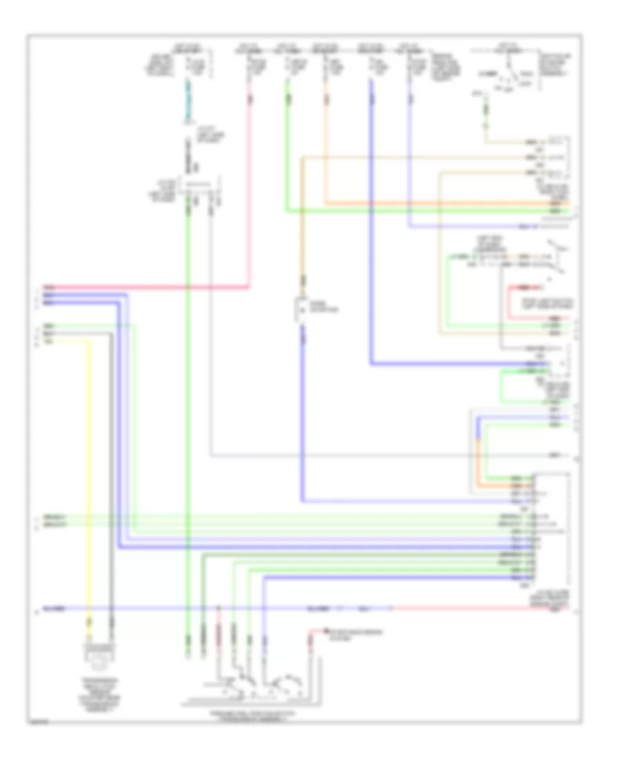
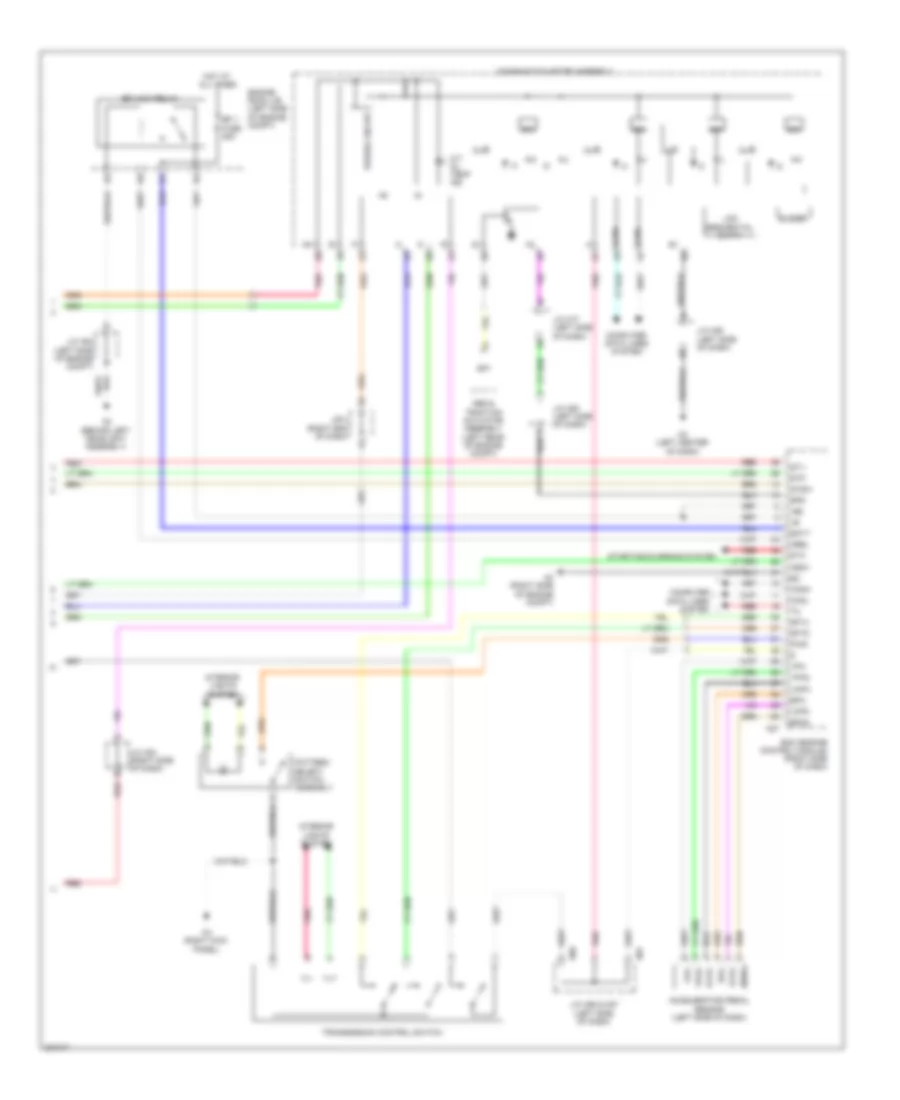
Automatic A/C Wiring Diagram (3 of 3) for Toyota Sequoia Limited 2010
List of elements for Automatic A/C Wiring Diagram (3 of 3) for Toyota Sequoia Limited 2010:
- (right rear quarterpanel) j/c p22
- +b2
- A/c amplifier assembly (right side of dash)
- A27
- Ac1
- Act
- Ad-4
- Ad-5
- Auto
- Blwh
- Connector housing color (brown)
- Connector housing color (gray)
- D56
- Damper servo motor (air mix)
- Damper servo motor (mode control)
- E f i engine coolant temperature sensor (left front of engine)
- Engine control module (ecm) (right side of dash)
- Engine controls system
- Gnd
- H1 (left kick panel)
- H3 (right kick panel)
- H54
- H67
- Ig+
- Integration control & panel assembly
- J/c h85 (left side of dash)
- Off
- Pnk
- Rbbu
- Rbug
- Rbus
- Rear blower fan motor (right gnd rear quarterpanel)
- Rear blower w/ fan motor sub assembly
- Rear cooling unit assembly (right rear quarterpanel)
- Rear room temperature sensor (cooler thermistor) (left rear quarterpanel)
- Red
- Rgnd
- Rlin
- S5-2
- Seats system
- Sg-5
- Sg-6
- Sgnd
- Shd+
- Shp+
- Spiral cable (steering column)
- Steering pad switch assembly
- Stx
- Tec
- Temp+
- Temp-
- Thermistor
- Thw e2 etha
- W/ stowing function & power rear seat
- Z12
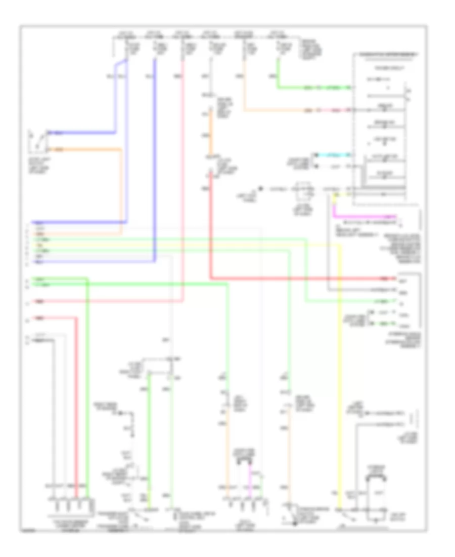
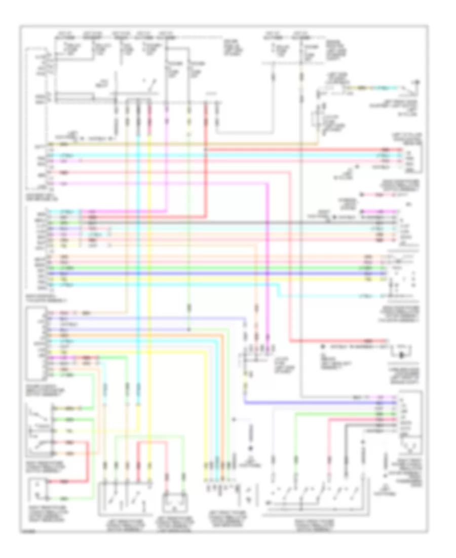
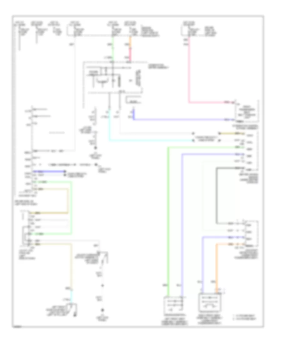
ANTI-LOCK BRAKES
Anti-lock Brakes Wiring Diagram (1 of 2) for Toyota Sequoia Limited 2010
List of elements for Anti-lock Brakes Wiring Diagram (1 of 2) for Toyota Sequoia Limited 2010:
- (behind left headlight assembly)
- (left side of dash) j/c h77 & h78
- (left side of dash) j/c h79 & h80
- +bm
- +bs
- A20
- A21
- A27
- A50
- A51
- Abs & traction actuator assembly (left rear of engine compt)
- B17
- Brake booster assembly (left rear of engine compt)
- Brk 1 relay
- Brk 2 relay
- Bst
- Bstp
- Bsw
- Canh
- Canl
- Computer data lines system
- Csw
- D/g
- D56
- Driver side j/b (left end of dash)
- Ecm (right side of dash)
- Ecu-ig 1 fuse 7.5a
- Engine room r/b (left side of engine compt)
- Exi2
- Fl+
- Fl-
- Fr+
- Fr-
- Gnd1
- Gyaw
- H77
- H78
- H79
- H80
- Hot in on or start
- Ig1
- Instrument cluster system
- J/c a48 (left end of dash)
- J/c a50 & a51 (right kick panel)
- J/c a52 (left end of dash)
- Left front wheel speed sensor (left front wheel hub assembly)
- Left rear wheel speed sensor (left rear wheel hub assembly)
- Pim
- Pkb2
- Pnk
- Psnc
- Psno
- Psoo
- Red
- Right front wheel speed sensor (right front wheel hub assembly)
- Right rear wheel speed sensor (right rear wheel hub assembly)
- Rl+
- Rl-
- Rr+
- Rr-
- Skid control warning buzzer (left end of dash)
- Sp1
- Ss1
- Ss2
- Stp
- Stp2
- Stpo
- Sts
- Stv
- Vcp
- Vys
Anti-lock Brakes Wiring Diagram (2 of 2) for Toyota Sequoia Limited 2010
List of elements for Anti-lock Brakes Wiring Diagram (2 of 2) for Toyota Sequoia Limited 2010:
- (4wd) (right side of dash)
- (brake fluid reservoir)
- (left center of dash) h2
- (right rear of engine)
- 4wd
- A1 (behind left headlight assembly)
- A28
- A50
- A51
- Abs 1 fuse 50a
- Abs 2 fuse 40a
- Abs ind
- Auto lsd ind
- B11
- B13
- B14
- Bat
- Brake fluid level warning switch (brake master cylinder reservoir sub- assembly)
- Brake ind
- Canh
- Canl
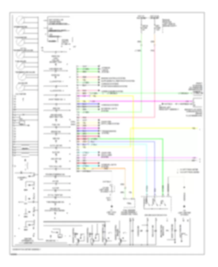
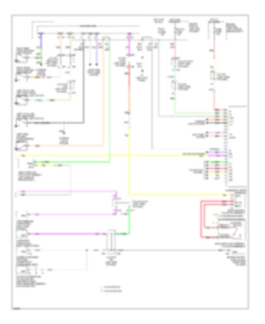
- Combination meter assembly
- Computer data lines system
- D14
- D45
- Dlc 3 (left side of dash)
- Driver side j/b (left end of dash)
- Ecu-b1 fuse 7.5a
- Engine room r/b (left side of engine compt)
- Ess
- Four wheel drive control ecu
- Gyaw
- H1 (left kick panel)
- H79
- Hot at all times
- Hot in on or start
- Interior lights system
- J/b 3 (right end of dash)
- J/c a50 & a51 (right kick panel)
- J/c d53 (right rear of engine compt)
- J/c h79 & h80 (left side of dash) h80
- J/c h85 (left side of dash)
- Met fuse 7.5a
- Met-b fuse 5a
- Parking brake switch (left side of dash)
- Pnk
- Power circuit
- Red
- Sil
- Slip ind
- Steering angle sensor (steering column assembly)
- Stop fuse 15a
- Stop light switch (left side of dash)
- Transfer shift actuator (4wd) (transfer case assembly)
- Vsc off ind
- Vsc off switch
- Vys
- Yaw rate sensor (under center console)
- Yaw1
- Yaw2
ANTI-THEFT
Forced Entry Wiring Diagram (1 of 2) for Toyota Sequoia Limited 2010
List of elements for Forced Entry Wiring Diagram (1 of 2) for Toyota Sequoia Limited 2010:
- (behind left headlight assembly) a2
- (left kick panel) h1
- (right "b" pillar) p1
- A27
- Acc
- Acc fuse 7.5a
- Act+
- Act-
- Actd
- Altb
- B13
- B18
- Becu
- Bzr
- C11
- C23
- C24
- Canh
- Canl
- Computer data lines system
- D40
- D49
- D51
- D53
- D55
- D56
- D62
- Dcty
- Detection unlock
- Dr/lck fuse 25a
- Driver side j/b (left end of dash)
- Ecu ig 2 fuse 7.5a
- Engine control module (ecm) (right side of dash)
- Exterior lights system
- Gnd1
- Gnd2
- H1 (left kick panel)
- H77
- H79
- H80
- Haz
- Hcty
- Headlights system
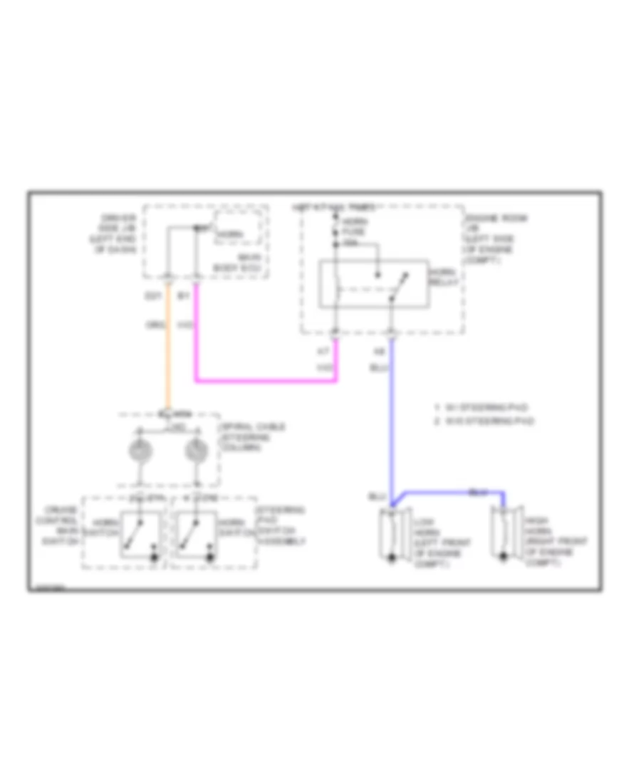
- Horn
- Horns system
- Hot at all times
- Hot in on or acc
- Hot in on or start
- Hrly
- Ile
- Ind
- Interior lights system
- J/c d55 (right rear of engine compt)
- J/c h77 & h78 (left side of dash) h78
- J/c h77 (left side of dash)
- J/c h78 (left side of dash)
- J/c h79 & h80 (left side of dash)
- J/c h80 (left side of dash)
- J/c h81 (left side of dash)
- Key lock
- Key unlock
- Ksw
- Lcty
- Left front door courtesy light switch (left "b" pillar)
- Left front door lock assembly (driver's door)
- Lh ig fuse 7.5a
- Lswd
- Lswl
- Lswp
- Lswr
- Main body ecu (driver side j/b)
- Park/neutral position switch (transmission assembly)
- Pcty
- Pnk
- Prg
- Rda
- Red
- Right front door courtesy light switch
- Right rear door courtesy light switch
- Right rear door lock assembly (right rear door)
- Rrcy
- Trly
- Ul1
- Ul3
- Unlock warning switch assembly (left side of dash)
- Wireless door lock buzzer (left front of engine compt)
Forced Entry Wiring Diagram (2 of 2) for Toyota Sequoia Limited 2010
List of elements for Forced Entry Wiring Diagram (2 of 2) for Toyota Sequoia Limited 2010:
- (left "b" pillar) o1
- (left "c" pillar) left rear door courtesy light switch
- (left kick panel) h1
- A4 (right side of engine compt)
- Accessory meter assembly
- Back door ecu (tailgate assembly)
- Bdcy
- Bdr
- Becu
- Courtesy
- Ctye
- D62
- Detection unlock
- Door control receiver (left "d" pillar)
- Door control switch assembly
- Driver side j/b (left end of dash)
- Ecu-b1 fuse 7.5a
- Engine hood courtesy switch
- Engine room r/b (left side of engine compt)
- Gnd
- H1 (left kick panel)
- H88
- H89
- Hot at all times
- J/c a46 (right side of dash)
- J/c h88 & h89 (behind center of dash)
- J/c o40 (left rear quarterpanel)
- J/c v19 (tailgate assembly)
- Left rear door lock assembly (left rear door)
- Lock
- Met b fuse 5a
- Mhtr
- O1 (left "b" pillar)
- Pnk
- Power fuse 30a
- Prg
- Rda
- Red
- Right front door lock assembly (front passenger's door)
- Security horn assembly (right rear of engine compt)
- Security horn relay
- Security indicator
- Unlock
- Unlock detection
- W/ motor back door lock assembly
- W/ power back door
- W/o power back door
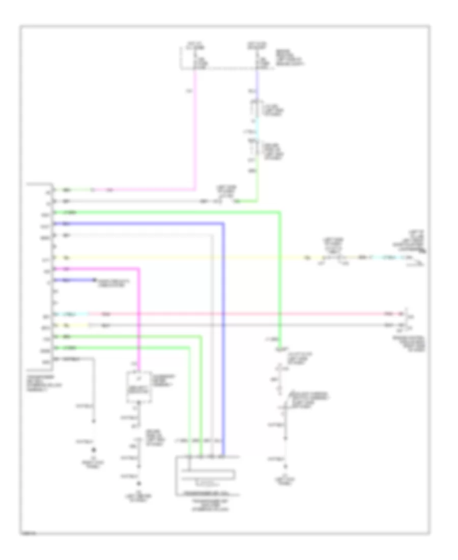
Immobilizer Wiring Diagram for Toyota Sequoia Limited 2010
List of elements for Immobilizer Wiring Diagram for Toyota Sequoia Limited 2010:
- (left "b" pillar) left front door courtesy light switch
- (left side of dash) j/c h77 & h78
- (left side of dash) j/c h82
- A27
- Accessory meter assembly
- Agnd
- B15
- Code
- Computer data lines system
- Cty
- D17
- D62
- Driver side j/b (left end of dash)
- Efii
- Efio
- Engine control module (ecm) (right side of dash)
- Engine room r/b (left side of engine compt)
- Gnd
- H1 (left kick panel)
- H2 (left center of dash)
- H3 (right kick panel)
- H77
- H78
- Hot at all times
- Hot in on or start
- Ign fuse 10a
- Imb fuse 7.5a
- Imi
- Imo
- Ind
- J/c a53 (left end of dash)
- J/c h77 & h78 (left side of dash)
- Ksw
- Pnk
- Security indicator
- Transponder key amplifier (steering column)
- Transponder key coil
- Transponder key ecu (steering column assembly)
- Txct
- Unlock warning switch assembly (left side of dash)
- Vc5
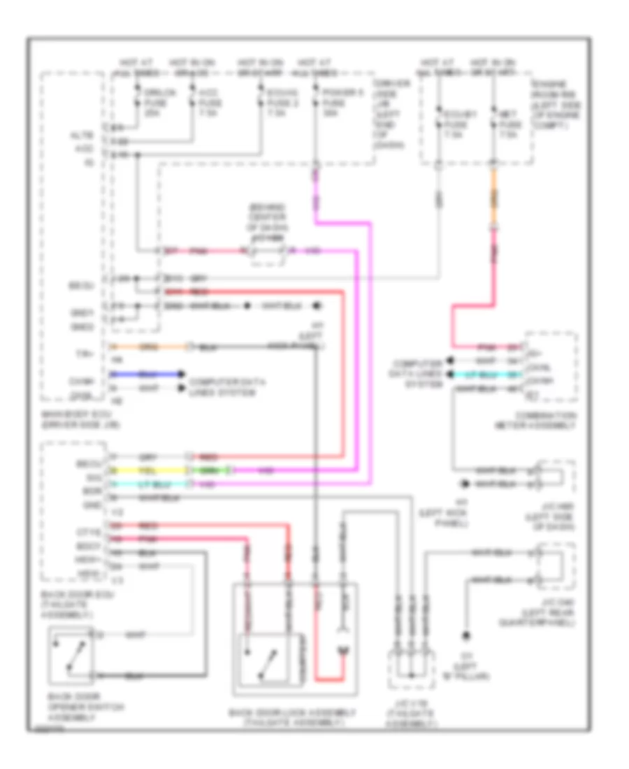
BODY CONTROL MODULES
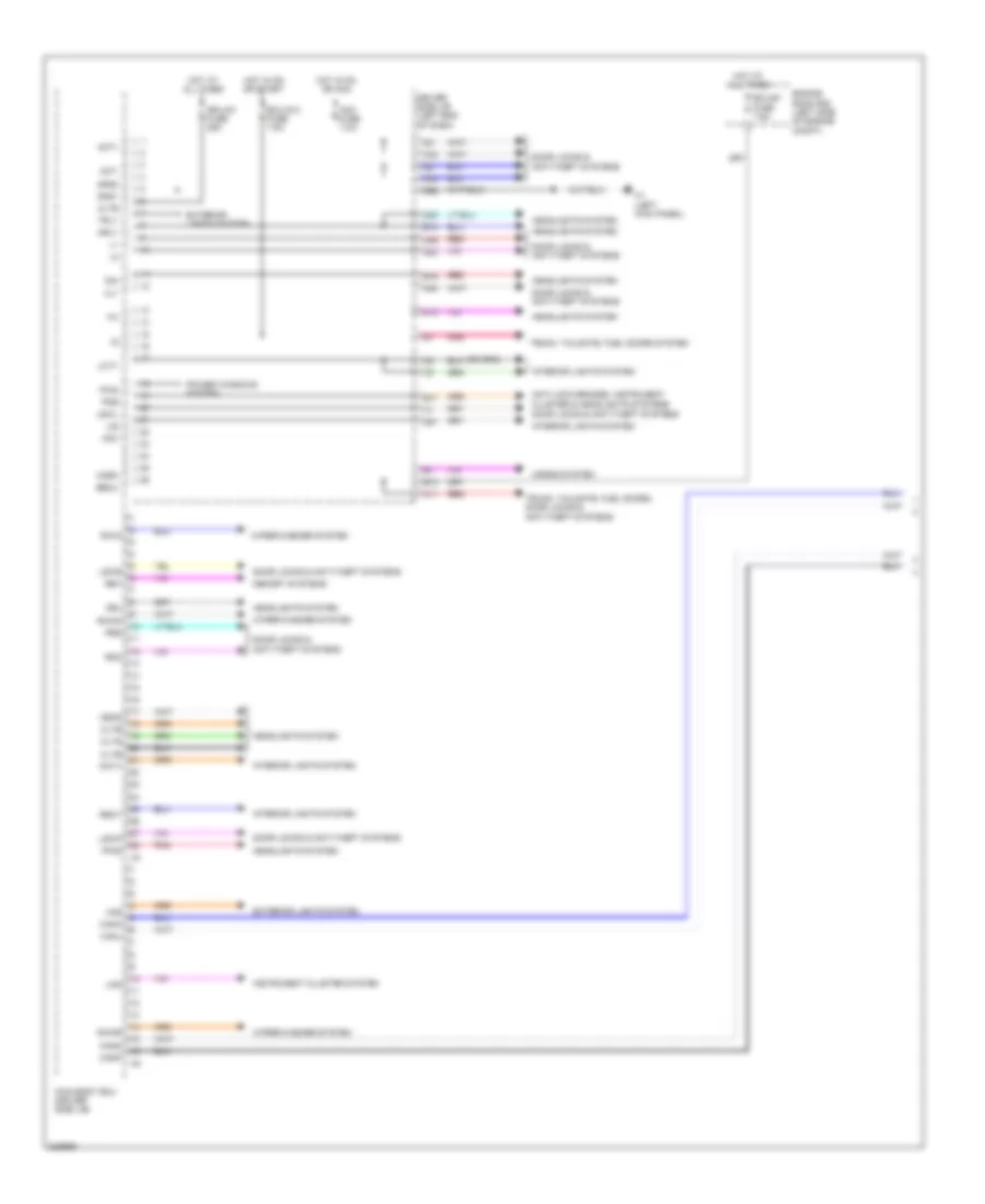
Body ECU Wiring Diagram (1 of 3) for Toyota Sequoia Limited 2010
List of elements for Body ECU Wiring Diagram (1 of 3) for Toyota Sequoia Limited 2010:
- Acc
- Acc fuse 7.5a
- Act+
- Act-
- Altb
- Anti-lock brakes, instrument cluster & headlights systems
- B11
- B13
- B16
- B18
- Becu
- C11
- C23
- C24
- Canh
- Canl
- Cann
- Canp
- Cltb
- Clte
- Clts
- D13
- D23
- D40
- D49
- D51
- D53
- D62
- Dim
- Door locks & anti-theft systems
- Dr/lck fuse 25a
- Driver side j/b (left end of dash)
- Drl
- Ecu-b1 fuse 7.5a
- Ecu-ig 2 fuse 7.5a
- Engine room r/b (left side of engine compt)
- Exterior lights system
- Ffog
- Gnd1
- Gnd2
- H1 (left kick panel)
- Haz
- Head
- Headlights system
- Horn
- Horns system
- Hot at all times
- Hot in on or acc
- Hot in on or start
- Hrly
- Ile
- Instrument cluster system
- Interior lights system
- Lcty
- Lin2
- Lswl
- Lswp
- Lswr
- Main body ecu (driver side j/b)
- Memory systems
- Pcty
- Pkb
- Pnk
- Power windows system
- Prg
- Pws
- Rda
- Red
- Ret
- Rrcy
- Rwin
- Rwmr
- Rwon
- Trly
- Trunk, tailgate, fuel doors system
- Trunk, tailgate, fuel doors, door locks & anti-theft systems
- Ul1
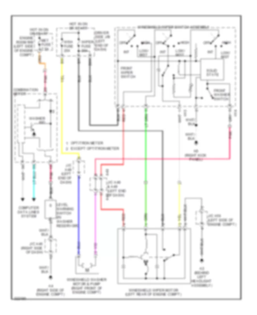
- Wiper/washer system
Body ECU Wiring Diagram (2 of 3) for Toyota Sequoia Limited 2010
List of elements for Body ECU Wiring Diagram (2 of 3) for Toyota Sequoia Limited 2010:
- (driver side j/b)
- (right side of dash) j/c h116
- A/c amplifier assembly (right side of dash)
- A27
- A28
- Actd
- Bzr
- Canh
- Canl
- Dcty
- Dlc 3 (data link connector 3) (left side of dash)
- Door locks & anti-theft systems
- Ecm (engine control module) (right side of dash)
- Exterior lights system
- Ffgo
- Four wheel drive control ecu (if equipped) (right side of dash)
- H24
- Hcty
- Headlights system
- Ind
- Interior lights system
- Ksw
- Lswd
- Main body ecu
- Memory systems
- Mirb
- Mire
- Mirs
- Pbds
- Pnk
- Red
- Rwsw
- Tail
- Tr+
- Trunk, tailgate, fuel doors system
- Ul3
- Warning systems
- Wiper/washer system
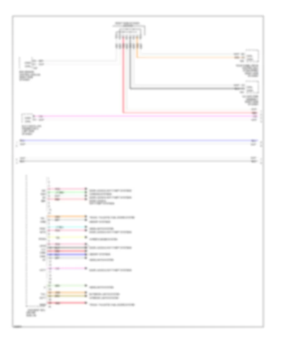
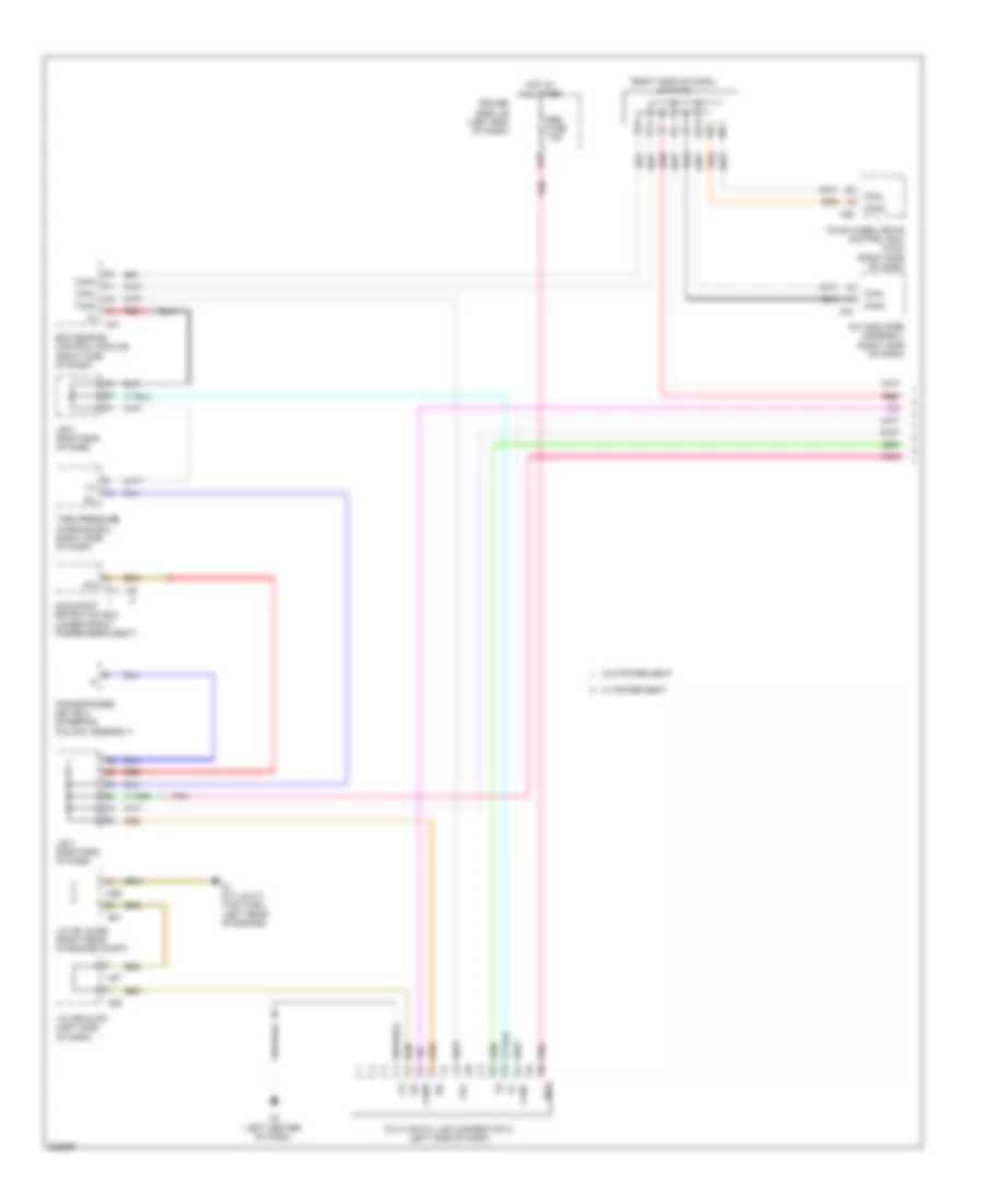
Body ECU Wiring Diagram (3 of 3) for Toyota Sequoia Limited 2010
List of elements for Body ECU Wiring Diagram (3 of 3) for Toyota Sequoia Limited 2010:
- (left end of dash) j/c a59, a60, h90, h91, h93, h94, h101, h103 & h106
- (under left rear seat) j/c o41 & o42
- A59
- A60
- Abs & traction actuator assembly (left rear of engine compt)
- Can
- Canh
- Canl
- Cann
- Canp
- Center air bag sensor (under center console)
- Cgnd
- Combination meter assembly
- Distance control ecu (left end of dash)
- H101
- H103
- H106
- H56
- H90
- H91
- H93
- H94
- J/c h115 (left end of dash)
- J/c o41 & o42 (under left rear seat)
- Left front power seat ecu & switch
- Multiplex tilt & telescopic ecu (steering column assembly)
- O18
- O19
- O41
- O42
- Outer mirror control ecu (left end of dash)
- Pnk
- Power back door unit assembly (left "d" pillar)
- Power steering ecu (left side of dash)
- Red
- Steering angle sensor (steering column assembly)
- Suspension control ecu (left rear quarterpanel)
- W/ air suspension
- W/ electronic modulated air suspension
- W/ memory
- W/ power back door & memory
- W/o air suspension
- W/o electronic modulated air suspension
- W/o power back door & w/ memory
- X11
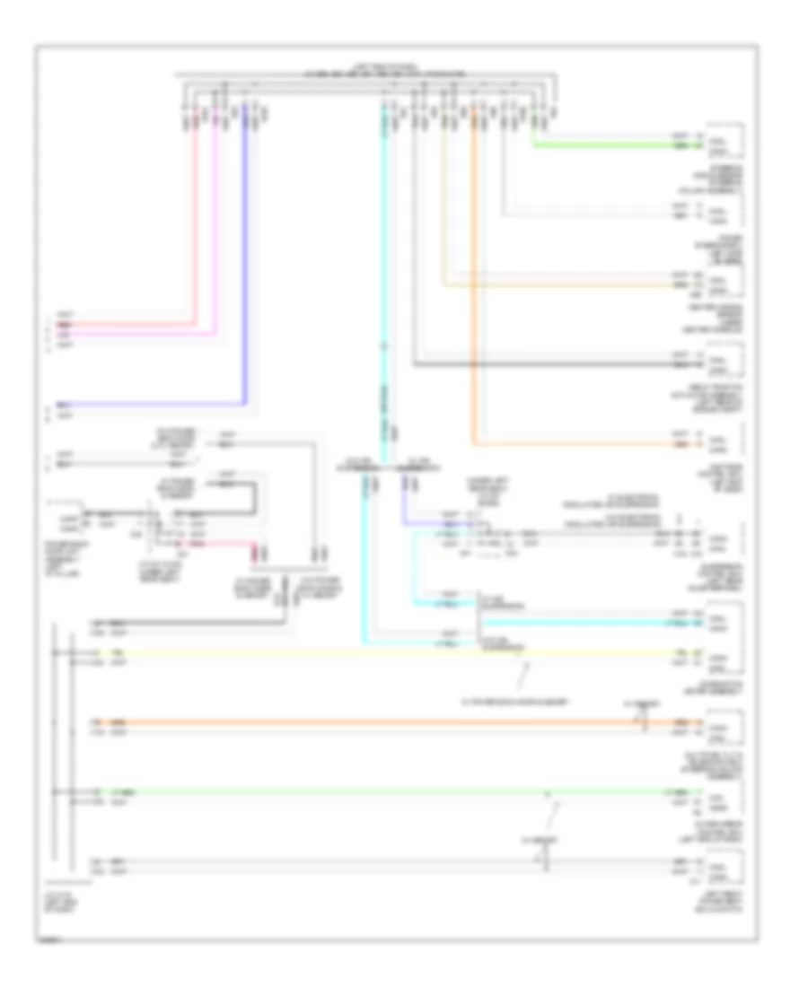
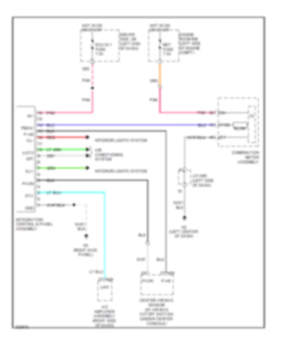
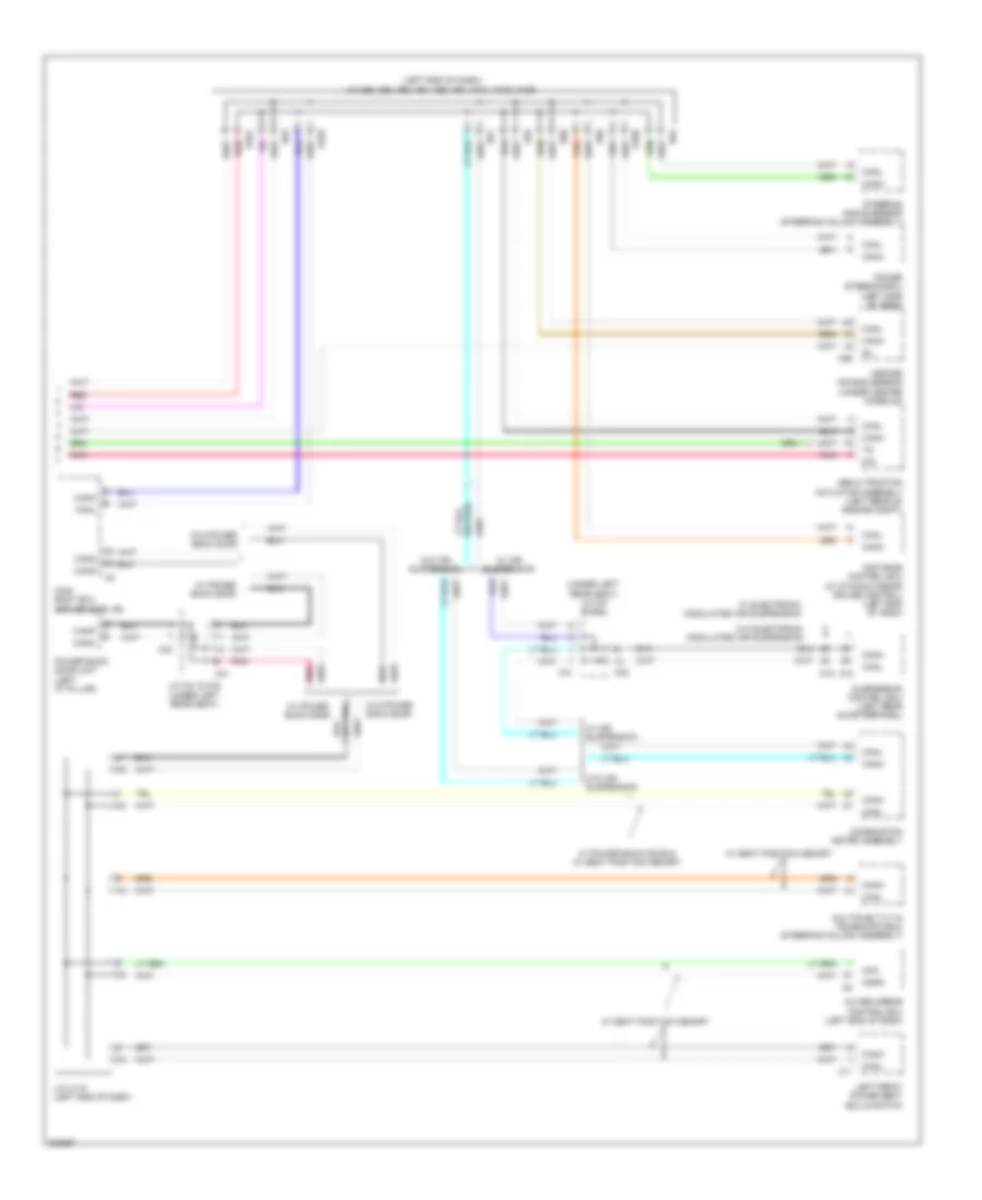
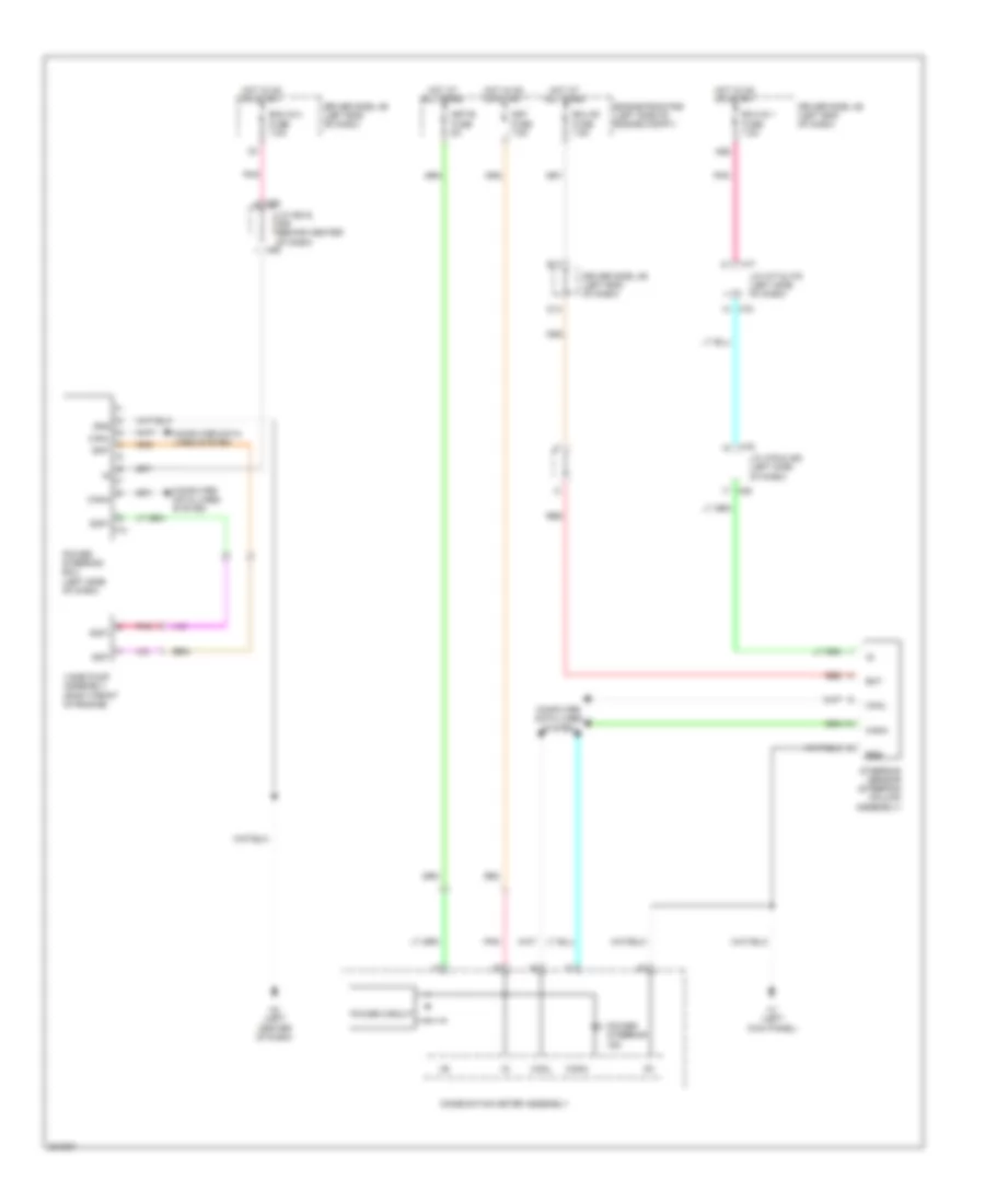
Integration Control and Panel Wiring Diagram for Toyota Sequoia Limited 2010
List of elements for Integration Control and Panel Wiring Diagram for Toyota Sequoia Limited 2010:
- A/c amplifier assembly (right side of dash)
- Air conditioning system
- Auto
- Blink
- Center air bag sensor (w/ air bag cutoff switch) (under center console)
- Combination meter assembly
- D56
- Driver side j/b (left end of dash)
- Ecu ig 1 fuse 7.5a
- Engine room r/b (left side of engine compt)
- Gnd
- H2 (left center of dash)
- H24
- H3 (right kick panel)
- H56
- Hot in on or start
- Ig+
- Ill+
- Ill-
- Integration control & panel assembly
- Interior lights system
- J/c h85 (left side of dash)
- Lin1
- Met fuse 7.5a
- Off
- P-ab
- P/sb
- Paon
- Pbew
- Pnk
- Red
- Stx
COMPUTER DATA LINES
Computer Data Lines Wiring Diagram (1 of 2) for Toyota Sequoia Limited 2010
List of elements for Computer Data Lines Wiring Diagram (1 of 2) for Toyota Sequoia Limited 2010:
- (right side of dash) j/c h116
- A/c amplifier assembly (right side of dash)
- A27
- A28
- A61
- Bat
- Canh
- Canl
- D1 (5.7l & 5.7l flex fuel) (left rear of engine)
- D18
- D55
- Dia
- Dlc 3 (data link connector 3) (left side of dash)
- Driver side j/b (left end of dash)
- Ecm (engine control module) (right side of dash)
- Four wheel drive control ecu (4wd) (right side of dash)
- H2 (left center of dash)
- H24
- H86
- H87
- Hot at all times
- J/b 3 (right end of dash)
- J/c a61 & d55 (right rear of engine compt)
- J/c h86 & h87 (left side of dash)
- Obd fuse 7.5a
- Occupant detection ecu (under front passenger's seat)
- P14
- Pnk
- Red
- Sil
- Tac
- Tach
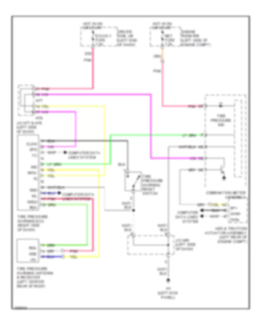
- Tire pressure warning ecu (right side of dash)
- Transponder key ecu (steering column assembly)
- W/ power seat
- W/o power seat
Computer Data Lines Wiring Diagram (2 of 2) for Toyota Sequoia Limited 2010
List of elements for Computer Data Lines Wiring Diagram (2 of 2) for Toyota Sequoia Limited 2010:
- (left end of dash) j/c a59, a60, h90, h91, h93, h94, h101, h103, h106
- (under left rear seat) j/c o41 & o42
- A59
- A60
- Abs & traction actuator assembly (left rear of engine compt)
- Can
- Canh
- Canl
- Cann
- Canp
- Center air bag sensor (under center console)
- Cgnd
- Combination meter assembly
- D/g
- Distance control ecu (w/ dynamic radar cruise control) (left end of dash)
- H101
- H103
- H106
- H56
- H90
- H91
- H93
- H94
- J/c h115 (left end of dash)
- J/c o41 & o42 (under left rear seat)
- Left front power seat ecu & switch
- Main body ecu (driver side j/b)
- Multiplex tilt & telescopic ecu (steering column assembly)
- O18
- O19
- O41
- O42
- Outer mirror control ecu (left end of dash)
- Pnk
- Power back door unit (left "d" pillar)
- Power steering ecu (left side of dash)
- Red
- Sil
- Steering angle sensor (steering column assembly)
- Suspension control ecu (left rear quarterpanel)
- W/ air suspension
- W/ electronic modulated air suspension
- W/ power back door
- W/ power back door & w/ seat position memory
- W/ seat position memory
- W/o air suspension
- W/o electronic modulated air suspension
- W/o power back door
- X11
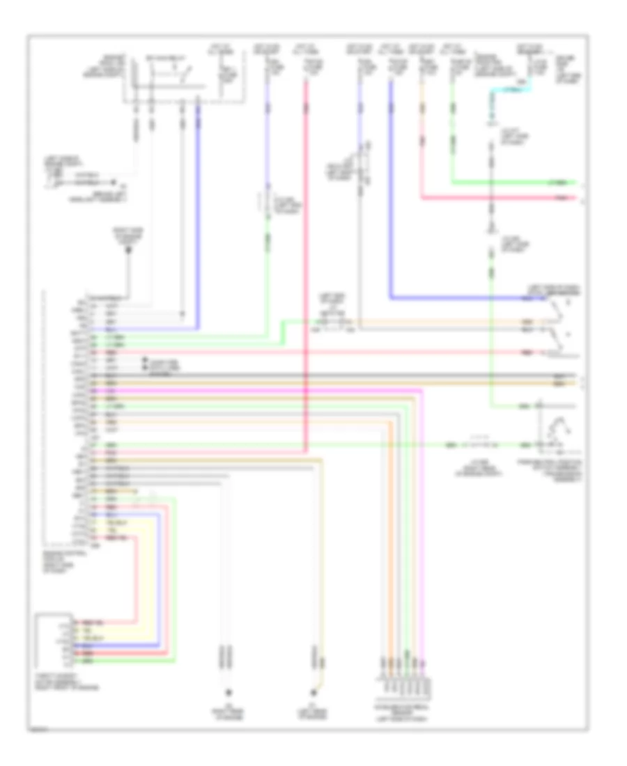
CRUISE CONTROL
Cruise Control Wiring Diagram (1 of 2) for Toyota Sequoia Limited 2010
List of elements for Cruise Control Wiring Diagram (1 of 2) for Toyota Sequoia Limited 2010:
- (behind left headlight assembly)
- (left end of dash) j/c a48 & a49
- (left rear of engine)
- (left side of dash) stop light switch
- (left side of engine compt) j/c a54
- (right rear of engine)
- (right side of engine compt) a4
- +b2
- +bm
- A27
- A48
- A49
- A52
- A53
- Accelerator pedal sensor (left side of dash)
- Batt
- Canh
- Canl
- Ccs
- Computer data lines system
- D55
- D56
- Driver side j/b (left end of dash)
- E04
- E05
- Efi 1 fuse 25a
- Efi main relay
- Engine control module (right side of dash)
- Engine room j/b (left side of engine compt)
- Engine room r/b (left side of engine compt)
- Epa
- Epa2
- Eta
- Etcs fuse 10a
- Ge01
- Hot at all times
- Hot in on or start
- Ign fuse 10a
- Igsw
- J/c a52 & a53 (left end of dash)
- J/c a53 (left end of dash)
- J/c d55 (right rear of engine compt)
- J/c h77 (left side of dash)
- J/c h80 (left side of dash)
- Lh-ig fuse 7.5a
- Me01
- Met fuse 7.5a
- Met-b fuse 5a
- Mrel
- Park/neutral position switch assembly (transmission assembly)
- Pnk
- Red
- Spd
- St1-
- Stop fuse 15a
- Stp
- Throttle body motor assembly (right front of engine)
- Vcp2
- Vcpa
- Vcta
- Vpa
- Vpa2
- Vta
- Vta1
- Vta2
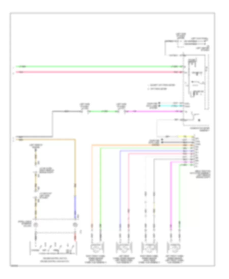
Cruise Control Wiring Diagram (2 of 2) for Toyota Sequoia Limited 2010
List of elements for Cruise Control Wiring Diagram (2 of 2) for Toyota Sequoia Limited 2010:
- (left kick panel) h1
- (left rear of engine) d1
- (left side of dash) j/c h77
- (left side of dash) j/c h80
- (left side of dash) j/c h85
- +res
- -set
- A61
- Abs & traction actuator assembly (left rear of engine compt)
- Cancel
- Canh
- Canl
- Combination meter assembly
- Computer data lines system
- Cruise control main switch
- Cruise control switch
- Cruise ind
- D55
- Dim
- Except optitron meter
- Fl+
- Fl-
- Fr+
- Fr-
- H2 (left center of dash)
- H54
- H86
- H87
- Ig+
- J/c a61 & d55 (right rear of engine compt)
- J/c h86 & h87 (left side of dash)
- Left front wheel speed sensor (left front wheel hub assembly)
- Left rear wheel speed sensor (left rear wheel hub assembly)
- On/ off
- Optitron meter
- Pnk
- Power circuit
- Red
- Right front wheel speed sensor (right front wheel hub assembly)
- Right rear wheel speed sensor (right rear wheel hub assembly)
- Rl+
- Rl-
- Rr+
- Rr-
- Sp1
- Spiral cable (steering column)
- Z11
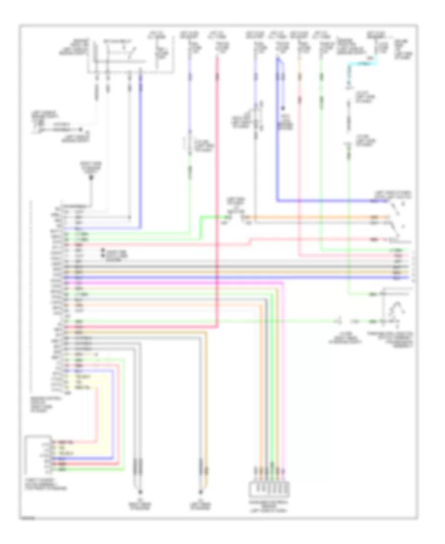
Dynamic Laser Cruise Control Wiring Diagram (1 of 2) for Toyota Sequoia Limited 2010
List of elements for Dynamic Laser Cruise Control Wiring Diagram (1 of 2) for Toyota Sequoia Limited 2010:
- (left end of dash) j/c a48 & a49
- (left side of dash) stop light switch
- (left side of engine compt) j/c a54
- (right side of engine compt) a4
- +b2
- +bm
- A2 (left side of engine compt)
- A27
- A48
- A49
- A52
- A53
- Accelerator pedal sensor (left side of dash)
- Anti- lock brakes system
- Batt
- Canh
- Canl
- Cchg
- Ccs
- Computer data lines system
- D1 (left rear of engine)
- D2 (right rear of engine)
- D55
- D56
- Driver side j/b (left end of dash)
- E04
- E05
- Efi 1 fuse 25a
- Efi main relay
- Engine control module (right side of dash)
- Engine room j/b (left side of engine compt)
- Engine room r/b (left side of engine compt)
- Epa
- Epa2
- Eta
- Etcs fuse 10a
- Ge01
- Hot at all times
- Hot in on or start
- Ign fuse 10a
- Igsw
- J/c a52 & a53 (left end of dash)
- J/c a53 (left end of dash)
- J/c d55 (right rear of engine compt)
- J/c h77 (left side of dash)
- J/c h80 (left side of dash)
- Lgnd
- Lh-ig fuse 7.5a
- Me01
- Met fuse 7.5a
- Met-b fuse 5a
- Mrel
- Park/neutral position switch assembly (transmission assembly)
- Pnk
- Red
- Spd
- St1-
- Stop fuse 15a
- Stp
- Throttle body motor assembly (top front of engine)
- Vcp2
- Vcpa
- Vcta
- Vpa
- Vpa2
- Vta
- Vta1
- Vta2
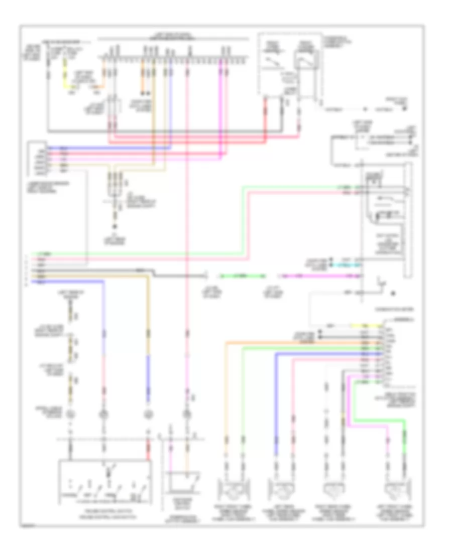
Dynamic Laser Cruise Control Wiring Diagram (2 of 2) for Toyota Sequoia Limited 2010
List of elements for Dynamic Laser Cruise Control Wiring Diagram (2 of 2) for Toyota Sequoia Limited 2010:
- (left end of dash) distance control ecu
- (left end of dash) j/c a52 & a53
- (left kick panel) h1
- (left rear of engine) d1
- (left side of dash) j/c h85
- (right kick panel) h3
- +res
- -set
- A52
- A53
- A61
- Abs & traction actuator assembly (left rear of engine compt)
- Assembly
- B12
- Cancel
- Canh
- Canl
- Combination meter
- Computer data lines system
- Cruise control main switch
- Cruise control switch
- Cruise ind
- D1 (left rear of engine)
- D55
- D66
- Dim
- Distance control switch
- Dot matrix lcd (odometer & other information)
- Driver side j/b (left end of dash)
- Ecu ig 2 fuse 7.5a
- Fl+
- Fl-
- Fr+
- Fr-
- Front washer switch
- Front wiper switch
- Gnd
- H14
- H15
- H2 (left center of dash)
- H54
- H86
- H87
- Hot in on or start
- Igb
- J/c a49 (left end of dash)
- J/c a61 & d55 (right rear of engine compt)
- J/c h77 (left side of dash)
- J/c h80 (left side of dash)
- J/c h86 & h87 (left side of dash)
- Laser radar sensor (left side of front bumper)
- Left front wheel speed sensor (left front wheel hub assembly)
- Left rear wheel speed sensor (left rear wheel hub assembly)
- Lgnd
- Lrdd
- Lrrd
- Mode
- On- off
- Pnk
- Power circuit
- Red
- Right front wheel speed sensor (right front wheel hub assembly)
- Right rear wheel speed sensor (right rear wheel hub assembly)
- Rl+
- Rl-
- Rr+
- Rr-
- Sgnd
- Sp1
- Spiral cable (steering column)
- Steering pad switch assembly
- Wash
- Windshield wiper switch assembly
- Wip2
- Wiper fuse 30a
- Wiper relay
- Z11
- Z12
DEFOGGERS
Front Deicer Wiring Diagram for Toyota Sequoia Limited 2010
List of elements for Front Deicer Wiring Diagram for Toyota Sequoia Limited 2010:
- A/c amplifier assembly (right side of dash)
- A1 (4.7l: left side of engine compt) (5.7l: behind left headlight assembly)
- A52
- A53
- Ambient temperature sensor (cooler thermistor 1) (left front of engine compt)
- B10
- Canh
- Canl
- Computer data lines system
- D56
- Deicer fuse 20a
- Deicer relay
- Driver side j/b (left end of dash)
- Ecu-ig 1 fuse 7.5a
- Engine room r/b (left side of engine compt)
- Front wiper deicer
- Front wiper deicer (left rear of engine compt)
- Front wiper deicer switch
- Gnd
- H24
- H3 (right kick panel)
- Hot at all times
- Hot in on or start
- Ig+
- Integration control & panel assembly
- J/c a47 (left end of dash)
- J/c a52 & a53 (left end of dash)
- Lh-ig fuse 7.5a
- Lin 1
- Pnk
- Red
- Sg-2
- Stx
- Tam
Heated Mirrors Wiring Diagram for Toyota Sequoia Limited 2010
List of elements for Heated Mirrors Wiring Diagram for Toyota Sequoia Limited 2010:
- A/c amplifier assembly (right side of dash)
- Ambient temperature sensor (cooler thermistor 1) (left front of engine compt)
- Canh
- Canl
- Computer data lines system
- D11
- D19
- D38
- D50
- D55
- D56
- Driver side j/b (left end of dash)
- Ecu-ig 1 fuse 7.5a
- Gnd
- H2 (left center of dash)
- H24
- H3 (right kick panel)
- H79
- H80
- Hot at all times
- Hot in on or start
- Ig+
- Integration control & panel assembly
- J/c a47 (left end of dash)
- J/c h77 (left side of dash)
- J/c h79 & h80 (left side of dash)
- Left outer rear view mirror assembly
- Lh-ig fuse 7.5a
- Lin 1
- Mhtr
- Mir fuse 15a
- Mir htr relay
- Mirror heater
- Pnk
- Rear window defogger switch
- Red
- Right outer rear view mirror assembly
- Sg-2
- Stx
- Tam
Rear Defogger Wiring Diagram for Toyota Sequoia Limited 2010
List of elements for Rear Defogger Wiring Diagram for Toyota Sequoia Limited 2010:
- A/c amplifier assembly (right side of dash)
- A2 (4.7l: left side of engine compt) (5.7l: behind left headlight assembly)
- A27
- Ambient temperature sensor (cooler thermistor 1) (left front of engine compt)
- B10
- Canh
- Canl
- Computer data lines system
- D56
- Def i/up fuse 5a
- Defog fuse 40a
- Defog relay
- Driver side j/b (left end of dash)
- Ecu-ig 1 fuse 7.5a
- Els2
- Engine control module (ecm) (right side of dash)
- Engine room r/b (left side of engine compt)
- Gnd
- H24
- H3 (right kick panel)
- Hot at all times
- Hot in on or start
- Ig+
- Integration control & panel assembly
- J/c a47 (left end of dash)
- J/c a53 (left end of dash)
- J/c a54 (left side of engine compt)
- Lh-ig fuse 7.5a
- Lin1
- Noise filter
- O1 (left "b" pillar)
- Pnk
- Rdfe
- Rear window defogger (back door v12 glass)
- Rear window defogger switch
- Red
- Sg-2
- Stx
- Tam
- V11
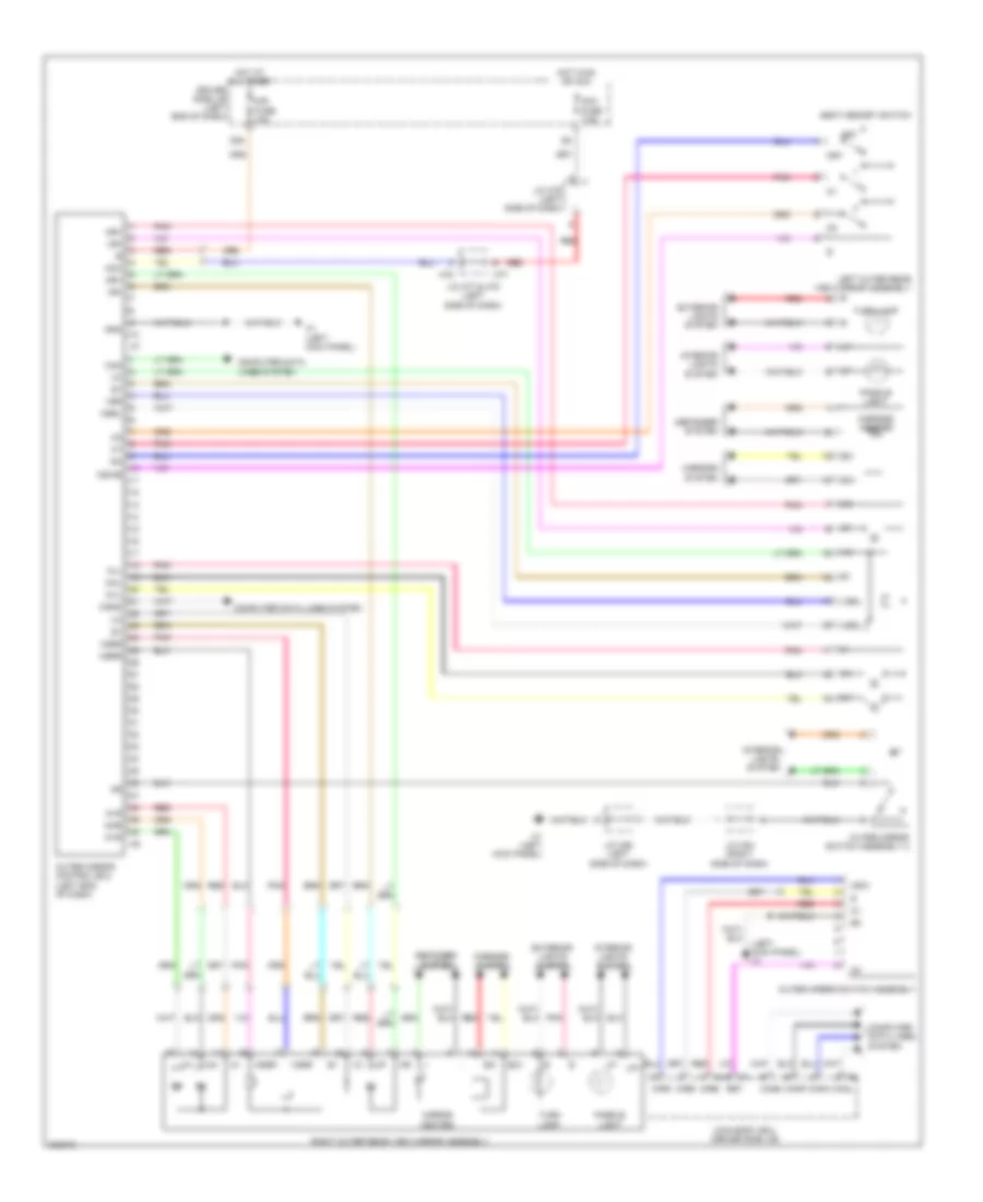
ELECTRONIC POWER STEERING
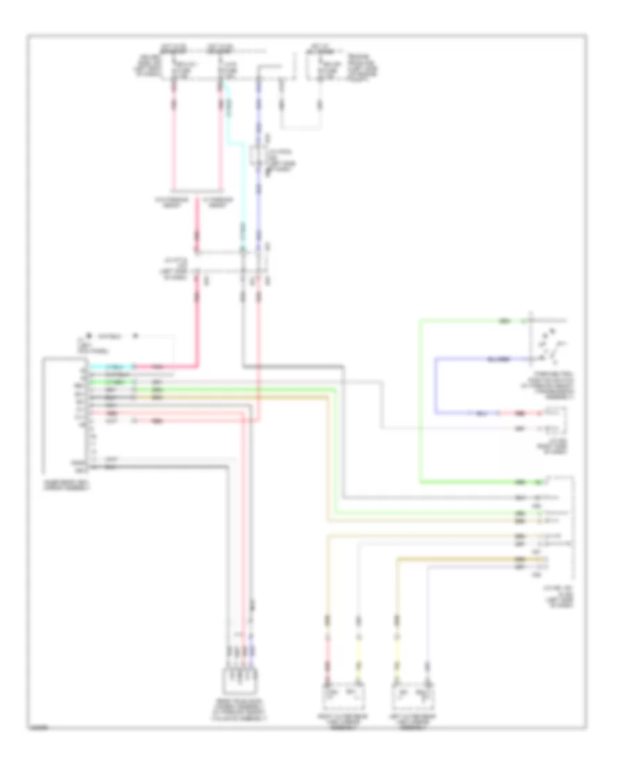
Electronic Power Steering Wiring Diagram for Toyota Sequoia Limited 2010
List of elements for Electronic Power Steering Wiring Diagram for Toyota Sequoia Limited 2010:
- (right front of engine)
- B13
- Bat
- Canh
- Canl
- Combination meter assembly
- Computer data lines system
- D14
- D56
- Driver side j/b (left end of dash)
- Ecu b1 fuse 7.5a
- Ecu-ig 1 fuse 7.5a
- Ecu-ig 2 fuse 7.5a
- Engine room r/b (left side of engine compt)
- Ess
- Gnd
- H1 (left kick panel)
- H2 (left center of dash)
- H77
- H78
- H79
- H80
- H88
- H89
- Hot at all times
- Hot in on or start
- J/c h77 & h78 (left side of dash)
- J/c h79 & h80 (left side of dash)
- J/c h88 & h89 (behind center of dash)
- Met fuse 7.5a
- Met-b fuse 5a
- Pnk
- Power circuit
- Power steering ecu (left side of dash)
- Power steering ind
- Red
- Sof+
- Sof-
- Steering sensor (steering column assembly)
- Vane pump assembly
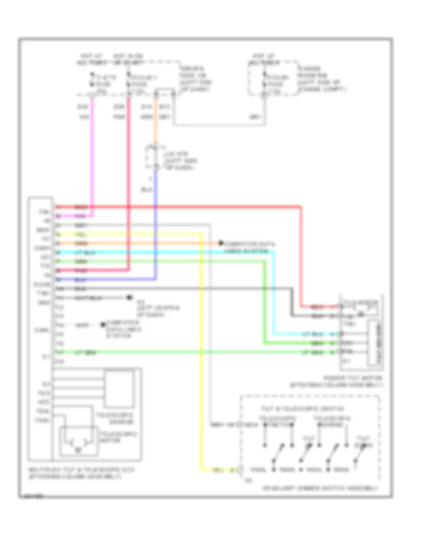
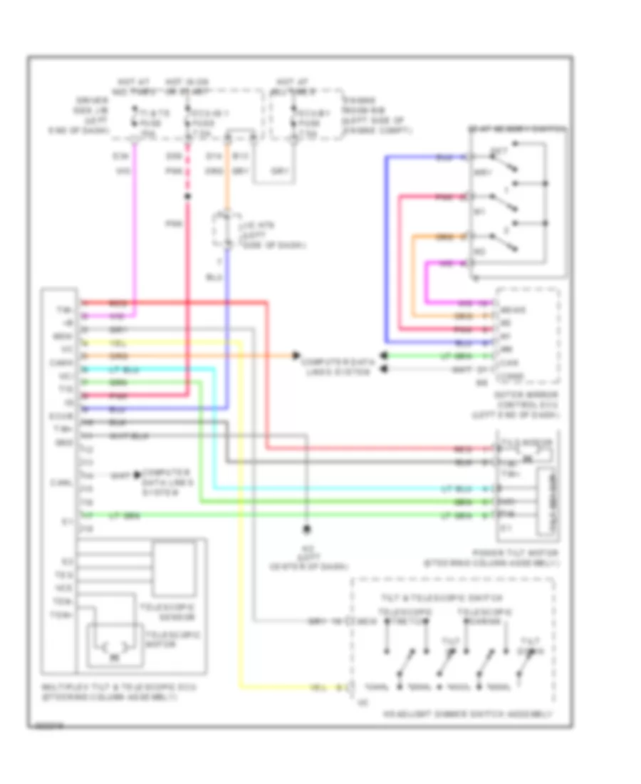
Power Tilt Steering Column Wiring Diagram for Toyota Sequoia Limited 2010
List of elements for Power Tilt Steering Column Wiring Diagram for Toyota Sequoia Limited 2010:
- B13
- Canh
- Canl
- Computer data lines system
- D14
- D34
- D56
- Driver side j/b (left end of dash)
- Ecu-b1 fuse 7.5a
- Ecu-ig 1 fuse 7.5a
- Ecub
- Engine room r/b (left side of engine compt)
- Gnd
- H2 (left center of dash)
- Headlight dimmer switch assembly
- Hot at all times
- Hot in on or start
- J/c h79 (left side of dash)
- Msw
- Multiplex tilt & telescopic ecu (steering column assembly)
- Pnk
- Power tilt motor (steering column assembly)
- Red
- Telescopic motor
- Telescopic sensor
- Telescopic shrink
- Telescopic stretch
- Tem+
- Tem-
- Tes
- Ti & te fuse 15a
- Tilt & telescopic switch
- Tilt down
- Tilt motor
- Tilt sensor
- Tilt up
- Tim+
- Tim-
- Tim- tim+
- Tis
- Vce
- Vci
ELECTRONIC SUSPENSION
Electronic Suspension Wiring Diagram, with Electronic Suspension (1 of 3) for Toyota Sequoia Limited 2010
List of elements for Electronic Suspension Wiring Diagram, with Electronic Suspension (1 of 3) for Toyota Sequoia Limited 2010:
- (left rear wheelwell) height control valve
- (left rear wheelwell) left rear height control sensor
- (right rear wheelwell) right rear height control sensor
- (right side of engine) right front absorber control actuator
- (under left rear corner of vehicle) height control exhaust valve
- A1 (behind left headlight assembly)
- Air sus 2 fuse 7.5a
- Air sus fuse 50a
- Air sus relay
- Dnsw
- Engine room r/b (left side of engine compt)
- Fal+
- Fal-
- Far+
- Far-
- Fbl+
- Fbl-
- Fbr+
- Fbr-
- Gnd
- H2 (left center of dash)
- Height control mode select switch
- Hot at all times
- Interior lights system
- J/c h84 (right side of dash)
- J/c h85 (left side of dash)
- J/c o39 (left rear quarterpanel)
- J/c o40 (left rear quarterpanel)
- Left front absorber control actuator (left side of engine)
- Left rear shock absorber assembly (left rear wheelwell)
- Lh+
- O1 (left "b" pillar)
- O16
- O17
- Pnk
- Q1 (under left rear of vehicle)
- Ral+
- Ral-
- Rar+
- Rar-
- Rbl+
- Rbl-
- Rbr+
- Rbr-
- Red
- Rh+
- Right acceleration sensor (right side of dash)
- Right rear shock absorber assembly (right rear wheelwell)
- Rm+
- Rm-
- Sbl2
- Sbr
- Sbr2
- Sbr3
- Sgfl
- Sgl2
- Sgr
- Sgr2
- Shb
- Shg
- Shrl
- Shrr
- Slex
- Slrl
- Slrr
- Suspension control ecu (left rear quarterpanel)
- Upsw
Electronic Suspension Wiring Diagram, with Electronic Suspension (2 of 3) for Toyota Sequoia Limited 2010
List of elements for Electronic Suspension Wiring Diagram, with Electronic Suspension (2 of 3) for Toyota Sequoia Limited 2010:
- B13
- Back door ecu (tailgate assembly)
- Back door lock assembly (tailgate assembly)
- Bdcy
- Becu
- Canh
- Canl
- Combination meter assembly
- Computer data lines system
- Courtesy switch
- Ctye
- Dcty
- Dim
- Driver side j/b (left end of dash)
- Ecu-b fuse 7.5a
- Engine room r/b (left side of engine compt)
- H1 (left kick panel)
- H77
- H78
- H79
- H80
- Height control compressor motor (under left rear corner of vehicle)
- Height control hi ind
- Height control lo ind
- Height control man ind
- Height control n ind
- Hot at all times
- J/c h77 & h78 (left side of dash)
- J/c h79 & h80 (left side of dash)
- J/c h79 & h80 (left side of dash) h80
- J/c h81 (left side of dash)
- J/c h85 (left side of dash)
- Lcty
- Left front door courtesy light switch (left "b" pillar)
- Left rear door courtesy light switch (left "c" pillar)
- Lin2
- Main body ecu (driver side j/b)
- Mpx1
- O2 (left quarterpanel)
- Pcty
- Pnk
- Red
- Right front door courtesy light switch
- Right rear door courtesy light switch
- Rm+
- Rm-
- Rrcy
Electronic Suspension Wiring Diagram, with Electronic Suspension (3 of 3) for Toyota Sequoia Limited 2010
List of elements for Electronic Suspension Wiring Diagram, with Electronic Suspension (3 of 3) for Toyota Sequoia Limited 2010:
- (left rear quarterpanel) j/c o39
- (left rear quarterpanel) j/c o40
- Air sus ig fuse 20a
- Canh
- Canl
- Computer data lines system
- Driver side j/b (left end of dash)
- Engine room r/b (left side of engine compt)
- Gnd
- H1 (left kick panel)
- H2 (left center of dash)
- Height control switch
- Hot w/ ig1 relay energized
- Hot w/ ig2 relay energized
- Interior lights system
- J/c h84 (right side of dash)
- J/c h85 (left side of dash)
- Left acceleration sensor (left side of dash)
- Met fuse 7.5a
- O1 (left "b" pillar)
- O18
- Pnk
- Red
- Sgfr
- Sgnd
- Sgr3
- Sgrr
- Sgv
- Suspension control ecu (left rear quarterpanel)
- Suspension control switch
- Tsw1
- Tsw2
Electronic Suspension Wiring Diagram, without Electronic Suspension (1 of 2) for Toyota Sequoia Limited 2010
List of elements for Electronic Suspension Wiring Diagram, without Electronic Suspension (1 of 2) for Toyota Sequoia Limited 2010:
- (left rear wheelwell) height control valve
- (right rear wheelwell) right rear height control sensor
- (under left rear corner of vehicle) height control exhaust valve
- A1 (behind left headlight assembly)
- Air sus 2 fuse 7.5a
- Air sus fuse 50a
- Air sus relay
- Bat
- Canh
- Canl
- Computer data lines system
- Dnsw
- Driver side j/b (left end of dash)
- Ecu ig 2 fuse 7.5a
- Engine room r/b (left side of engine compt)
- Gnd
- H2 (left center of dash)
- Height control mode select switch
- Height control switch
- Hot at all times
- Hot in on or start
- Hot w/ ig2 relay energized
- Interior lights system
- J/c h84 (right side of dash)
- J/c h85 (left side of dash)
- J/c h88 (behind center of dash)
- J/c o39 (left rear quarterpanel)
- J/c o40 (left rear quarterpanel)
- Left rear height control sensor (left rear wheelwell)
- Lh+
- Met fuse 7.5a
- O1 (left "b" pillar)
- Pnk
- Q1 (under left rear of vehicle)
- Red
- Rh+
- Rm+
- Rm-
- Sbl2
- Sbr2
- Sgl2
- Sgr2
- Shb
- Shg
- Shrl
- Shrr
- Slex
- Slrl
- Slrr
- Suspension control ecu (left rear quarterpanel)
- Upsw
Electronic Suspension Wiring Diagram, without Electronic Suspension (2 of 2) for Toyota Sequoia Limited 2010
List of elements for Electronic Suspension Wiring Diagram, without Electronic Suspension (2 of 2) for Toyota Sequoia Limited 2010:
- B13
- Back door ecu (tailgate assembly)
- Back door lock assembly (tailgate assembly)
- Bdcy
- Becu
- Canh
- Canl
- Combination meter assembly
- Computer data lines system
- Courtesy switch
- Ctye
- Dcty
- Dim
- Driver side j/b (left end of dash)
- Ecu-b fuse 7.5a
- Engine room r/b (left side of engine compt)
- H1 (left kick panel)
- H77
- H78
- H79
- H80
- Height control compressor motor (under left rear corner of vehicle)
- Height control hi ind
- Height control lo ind
- Height control man ind
- Height control n ind
- Hot at all times
- J/c h77 & h78 (left side of dash)
- J/c h79 & h80 (left side of dash)
- J/c h79 & h80 (left side of dash) h80
- J/c h81 (left side of dash)
- J/c h85 (left side of dash)
- Lcty
- Left front door courtesy light switch (left "b" pillar)
- Left rear door courtesy light switch (left "c" pillar)
- Lin2
- Main body ecu (driver side j/b)
- Mpx1
- O2 (left quarterpanel)
- Pcty
- Pnk
- Red
- Right front door courtesy light switch
- Right rear door courtesy light switch
- Rm+
- Rm-
- Rrcy
- W/ power back door
- W/o power back door
ENGINE PERFORMANCE
4.6L
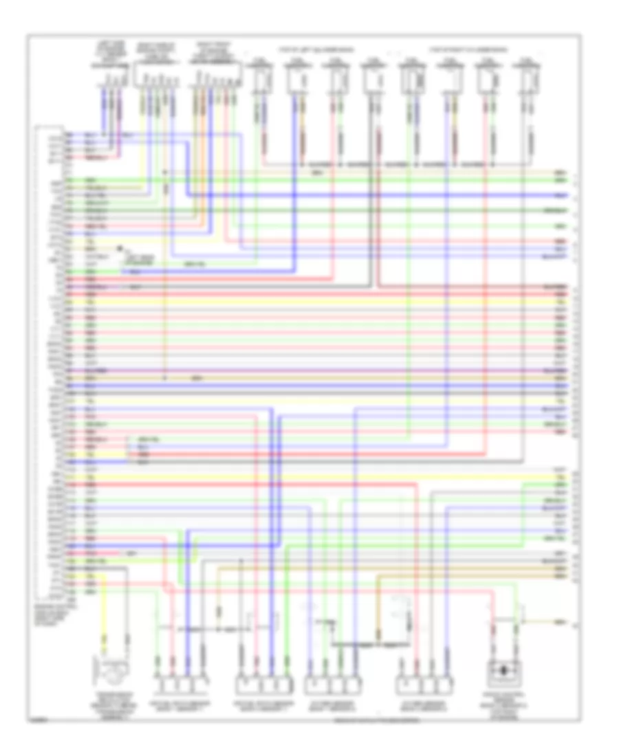
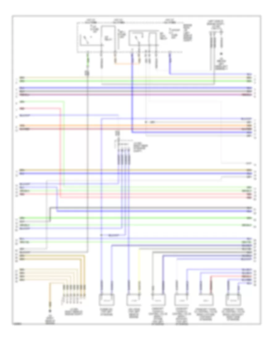
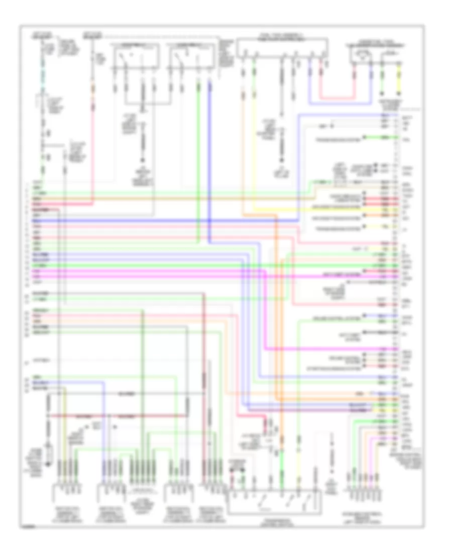
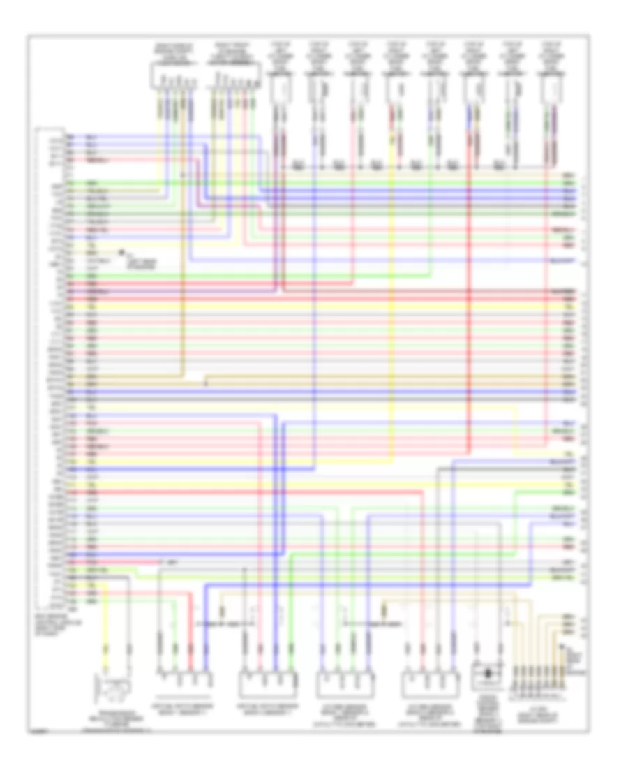
4.6L, Engine Performance Wiring Diagram (1 of 7) for Toyota Sequoia Limited 2010
List of elements for 4.6L, Engine Performance Wiring Diagram (1 of 7) for Toyota Sequoia Limited 2010:
- (left side of engine) vvt sensor (bank 1 exhaust side)
- (rear of catalytic converter)
- (right front of engine) throttle body motor assembly
- (right side of engine compt) mass air flow meter
- (top of left cylinder bank)
- (top of right cylinder bank)
- A1a+
- A1a-
- A2a+
- A2a-
- Air fuel ratio sensor (bank 1 sensor 1)
- Air fuel ratio sensor (bank 2 sensor 1)
- D1 (left rear of engine)
- D56
- E2g
- Ekn2
- Ekn3
- Ekn4
- Eknk
- Engine control module (ecm) (right side of dash)
- Eta
- Ev1+
- Ev1-
- Ex+
- Ex-
- Ex1b
- Ex2b
- Fuel injector 1
- Fuel injector 2
- Fuel injector 3
- Fuel injector 4
- Fuel injector 5
- Fuel injector 6
- Fuel injector 7
- Fuel injector 8
- G2-
- Ha1a
- Ha2a
- Ht1b
- Ht2b
- Igf1
- Igf2
- Knk1
- Knk2
- Knk3
- Knk4
- Knock control sensor (bank 2 sensor 2) (top right of engine)
- Me01
- Nca
- Ne+
- Ne-
- Nsw
- Nt+
- Nt-
- Ox1b
- Ox2b
- Oxygen sensor (bank 1 sensor 2)
- Oxygen sensor (bank 2 sensor 2)
- Pim
- Pnk
- Ppmp
- Psp
- Red
- Sp2+
- Sp2-
- Tha
- Tho1
- Tho2
- Thw
- Transmission revolution sensor (turbine) (transmission assembly)
- Vc2
- Vcta
- Vcv1
- Vcv2
- Vta
- Vta1
- Vta2
- Vv1+
- Vv1-
- Vv2+
- Vv2-
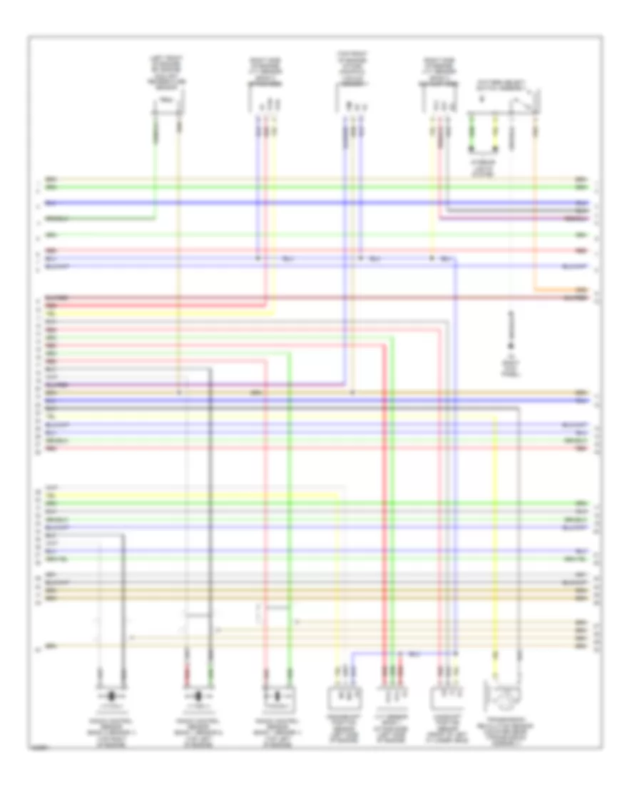
4.6L, Engine Performance Wiring Diagram (2 of 7) for Toyota Sequoia Limited 2010
List of elements for 4.6L, Engine Performance Wiring Diagram (2 of 7) for Toyota Sequoia Limited 2010:
- (left front of engine) efi engine coolant temperature sensor
- (right side of engine) vvt sensor (bank 2 exhaust side)
- (right side of engine) vvt sensor (bank 2 intake side)
- (top front of engine) intake manifold vacuum sensor
- Camshaft position sensor (front of left cylinder head)
- Crankshaft position sensor (left side of engine)
- Ex+
- Ex-
- H3 (right kick panel)
- Interior lights system
- Knock control sensor (bank 1 sensor 1) (top left of engine)
- Knock control sensor (bank 1 sensor 2) (top left of engine)
- Knock control sensor (bank 2 sensor 1) (top right of engine)
- Ne+
- Ne-
- Pattern select switch assembly
- Pim
- Red
- Transmission revolution sensor (counter gear) (transmission assembly)
- Vc2
- Vvl+
- Vvl-
- Vvr+
- Vvr-
- Vvt sensor (bank 1 intake side) (left side of engine)
4.6L, Engine Performance Wiring Diagram (3 of 7) for Toyota Sequoia Limited 2010
List of elements for 4.6L, Engine Performance Wiring Diagram (3 of 7) for Toyota Sequoia Limited 2010:
- (left side of engine compt) j/c a54
- A/f fuse 15a
- A/f relay
- A/pump fuse 50a
- A2 (behind left headlight assembly)
- Camshaft timing oil control valve (bank 1 exhaust) (top left of engine)
- Camshaft timing oil control valve (bank 1 intake) (top left of engine)
- Camshaft timing oil control valve (bank 2 exhaust) (right side of engine)
- Camshaft timing oil control valve (bank 2 intake) (top right of engine)
- D2 (right rear of engine)
- Efi 1 fuse 25a
- Efi main relay
- Engine room j/b (left side of engine compt)
- Hot at all times
- J/c d53 (right rear of engine compt)
- Purge vsv (top left of engine)
- Red
- Vsv (acis) (top left rear of engine)
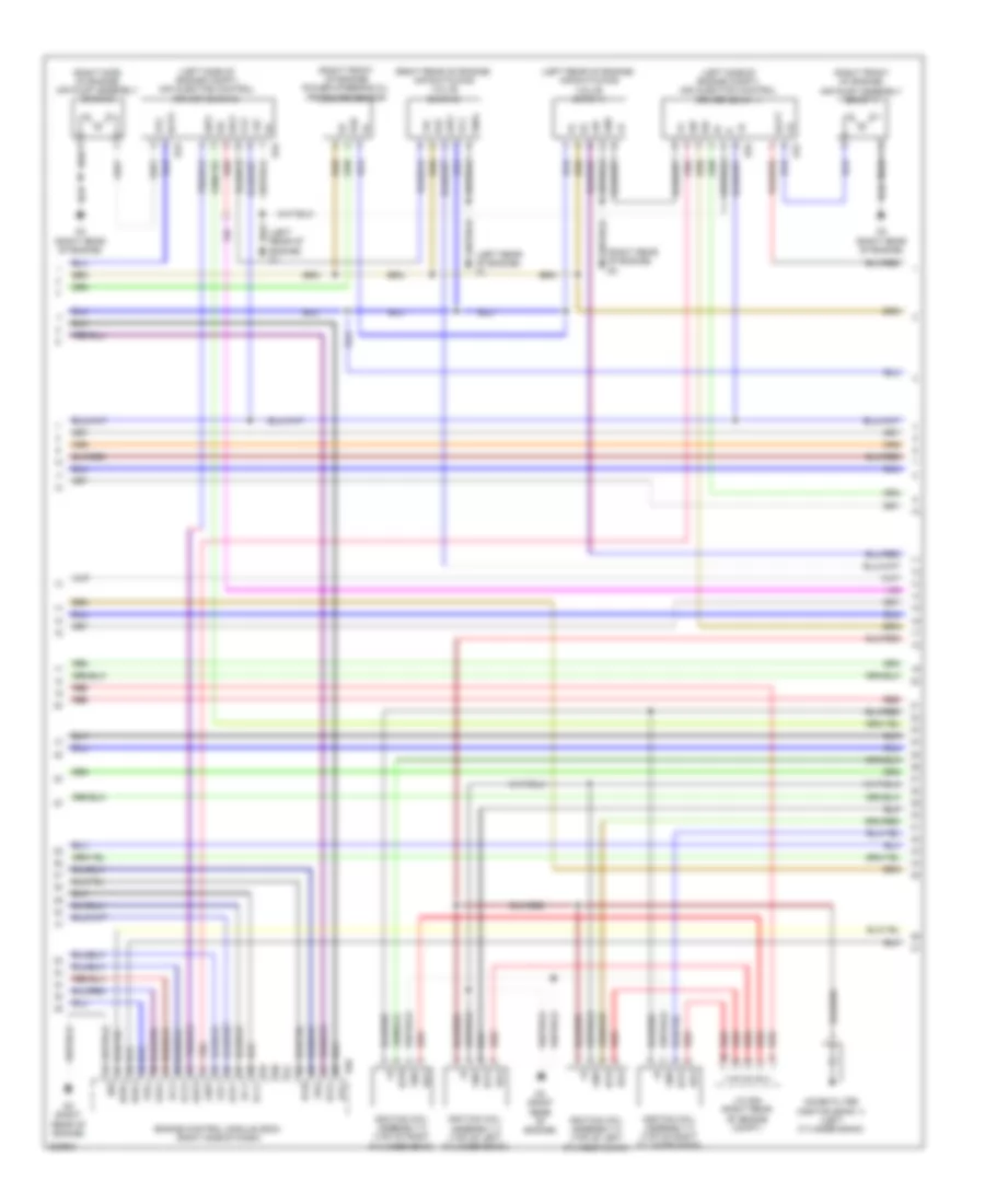
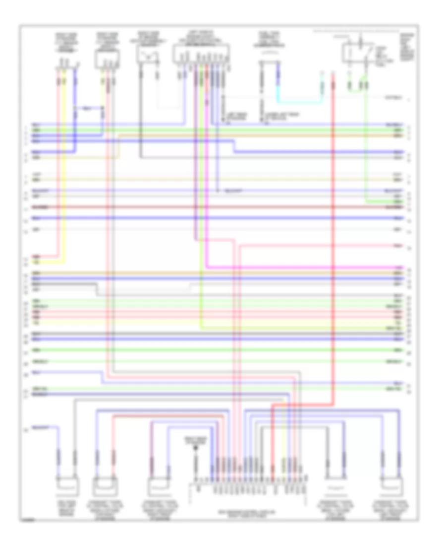
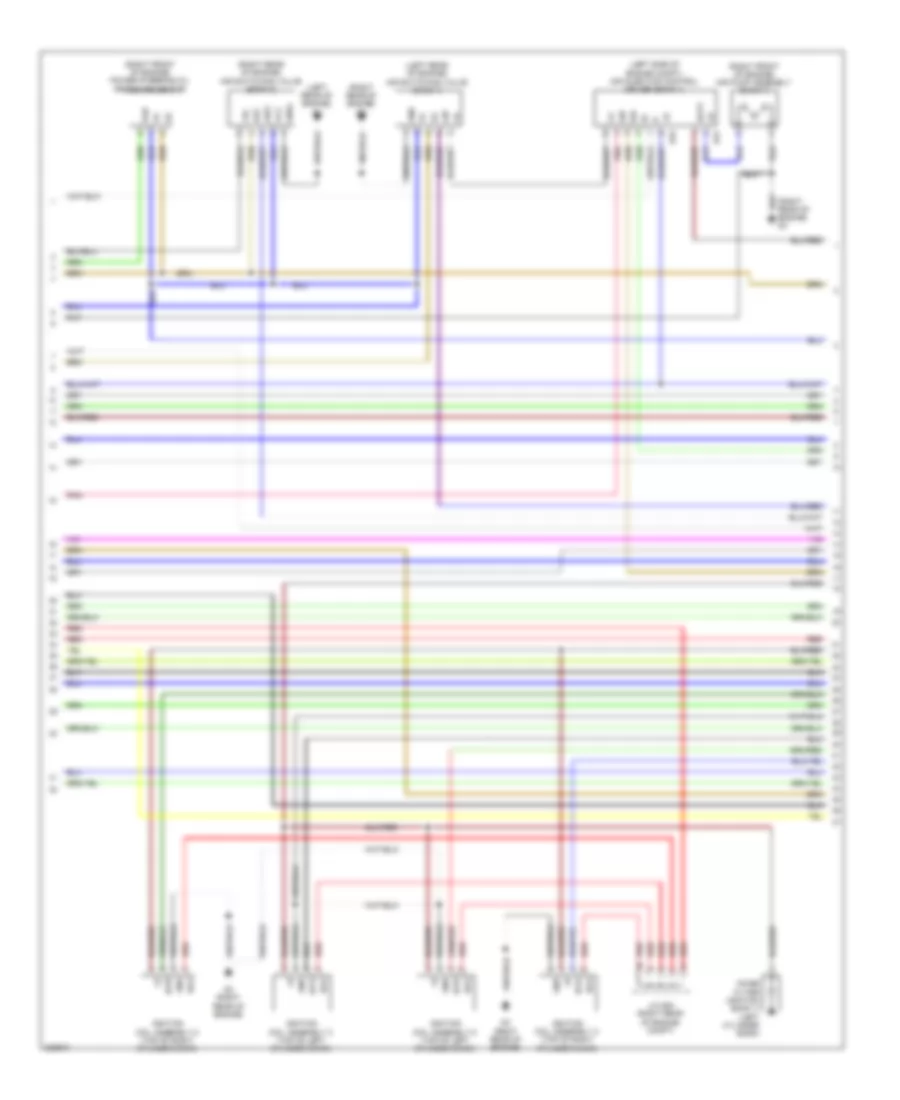
4.6L, Engine Performance Wiring Diagram (4 of 7) for Toyota Sequoia Limited 2010
List of elements for 4.6L, Engine Performance Wiring Diagram (4 of 7) for Toyota Sequoia Limited 2010:
- (left rear of engine) air switching valve (bank 1)
- (left rear of engine) d1
- (left side of engine compt) air injection control driver (bank 1)
- (left side of engine compt) air injection control driver (bank 2)
- (right front of engine) air pump assembly (bank 1)
- (right front of engine) power steering oil pressure sensor
- (right rear of engine) air switching valve (bank 2)
- (right rear of engine) d3
- (right side of engine) air pump assembly (bank 2)
- +b2
- +bl
- Acis
- Aip
- Aip2
- Airp
- Arp2
- Bat2
- Batt
- D2 (right rear of engine)
- D3 (right rear of engine)
- D31
- D32
- D33
- D34
- D56
- Di2
- E03
- E22
- Egr1
- Egr4
- Engine control module (ecm) (right side of dash)
- Ev2+
- Ev2-
- Gnd
- Gndl
- Igf2
- Ignition coil assembly 2 (top of right cylinder bank)
- Ignition coil assembly 3 (top of left cylinder bank)
- Ignition coil assembly 5 (top of left cylinder bank)
- Ignition coil assembly 8 (top of right cylinder bank)
- Igt2
- Igt3
- Igt5
- Igt8
- J/c d54 (right rear of engine compt)
- Noise filter (ignition bank 1) (left cylinder bank)
- Oc1+
- Oc1-
- Oc2+
- Oc2-
- Oe1+
- Oe1-
- Oe2+
- Oe2-
- Pnk
- Prg
- Psp
- Red
- Sip
- Sip2
- Siv
- Siv2
- Vc2
- Vp2
- Vv2
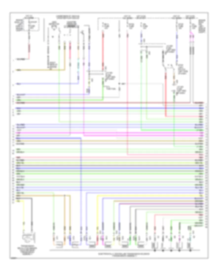
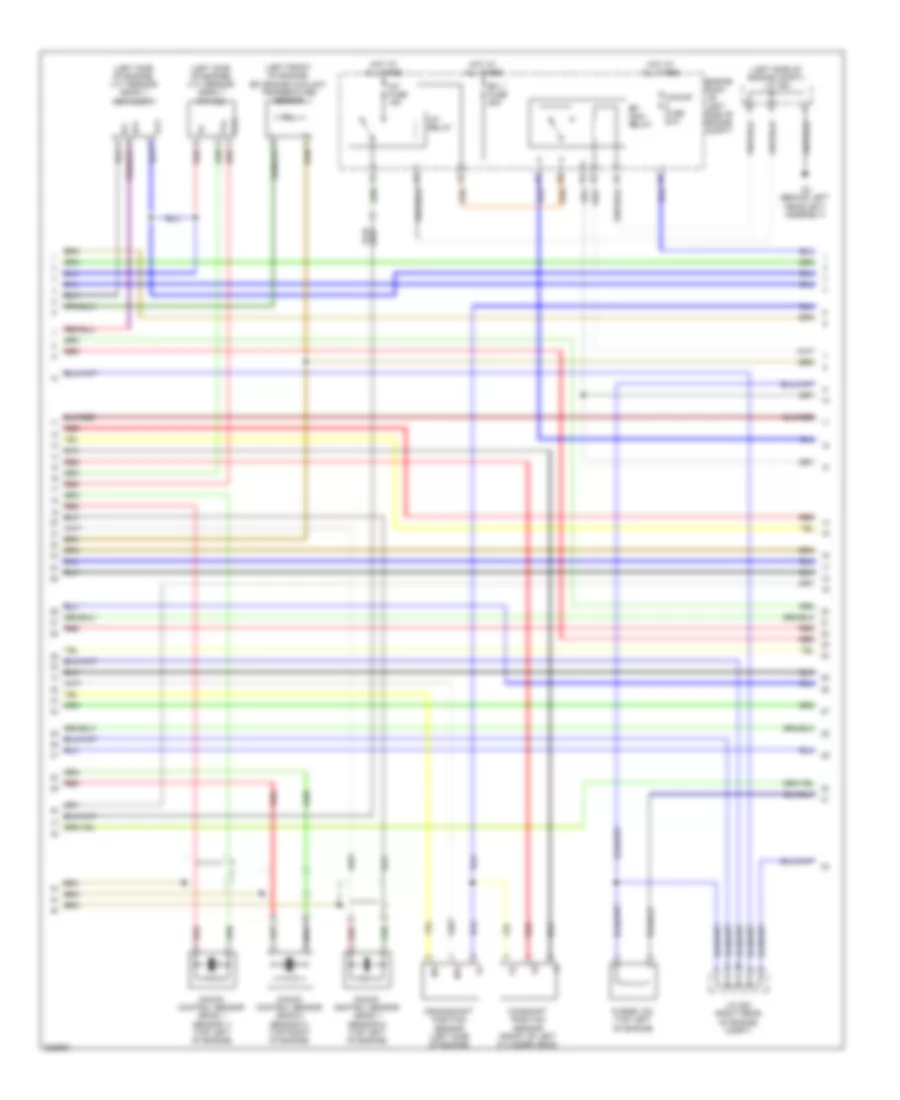
4.6L, Engine Performance Wiring Diagram (5 of 7) for Toyota Sequoia Limited 2010
List of elements for 4.6L, Engine Performance Wiring Diagram (5 of 7) for Toyota Sequoia Limited 2010:
- (right rear of engine) d2
- (under rear of vehicle) canister pump module
- +b1
- +b2
- A/pump fuse 50a
- A48
- A53
- Canister pressure sensor
- Efi 2 fuse 10a
- Egr control valve sub assembly (right rear of engine)
- Egr1
- Egr2
- Egr3
- Egr4
- Electronically controlled transmission solenoid (transmission assembly)
- Engine room j/b (left side of engine compt)
- Engine room r/b (left side of engine compt)
- Etcs fuse 10a
- F/pmp fuse 15a
- Hot at all times
- Hot in on or start
- Ign fuse 10a
- Inj fuse 10a
- J/c a48 & a49 (left end of dash) a49
- J/c a52 & a53 (left end of dash) a52
- J/c a53 (left end of dash)
- Leak detection pump
- Ot+
- Ot-
- Ot2+
- Ot2-
- Pnk
- Red
- Sl1+
- Sl1-
- Sl2+
- Sl2-
- Slt+
- Slt-
- Slu+
- Slu-
- Stop fuse 15a
- Stop light switch (left side of dash)
- Vent valve
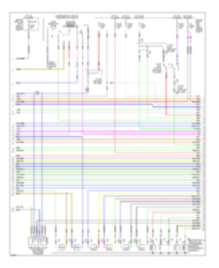
4.6L, Engine Performance Wiring Diagram (6 of 7) for Toyota Sequoia Limited 2010
List of elements for 4.6L, Engine Performance Wiring Diagram (6 of 7) for Toyota Sequoia Limited 2010:
- (left rear of engine) d1
- (right
- +bm
- A/t oil temperature ind
- A50
- A51
- A61
- Acc
- Aid2
- Aidi
- Airv
- Alt
- Buzzer
- Canh
- Canl
- Combination meter assembly
- Computer data lines system
- D2 (right rear of engine)
- D55
- D56
- Dim
- Diode (starting)
- E01
- E02
- E04
- E05
- Egr2
- Egr3
- Engine control module (ecm) (right side of dash)
- Ge01
- H1 (left kick panel)
- Ha1a
- Ha2a
- Hot at all times
- Ht1b
- Ht2b
- Ignition or starter switch assembly
- Igt1
- Igt2
- Igt3
- Igt4
- Igt5
- Igt6
- Igt7
- Igt8
- Instrument cluster system
- J/b 3 (right end of dash)
- J/c a50 & a51 (right a51 kick panel)
- J/c d55 & a61 (right rear of engine compt) d55
- J/c h77 (left side of dash)
- J/c h83 (right side of dash)
- J/c h85 (left side of dash)
- Lcd (sequential shift)
- Lock
- Malfunction indicator lamp
- Off
- Park/neutral position switch (transmission assembly)
- Pnk
- Power circuit
- Rear of engine) d2
- Red
- Sl1+
- Sl1-
- Sl2+
- Sl2-
- Slt+
- Slt-
- Slu+
- Slu-
- Star
- Start
- Starting/ charging system
- Starting/charging system
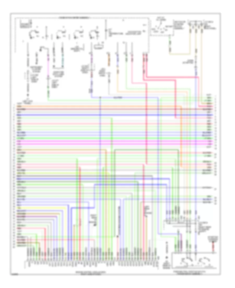
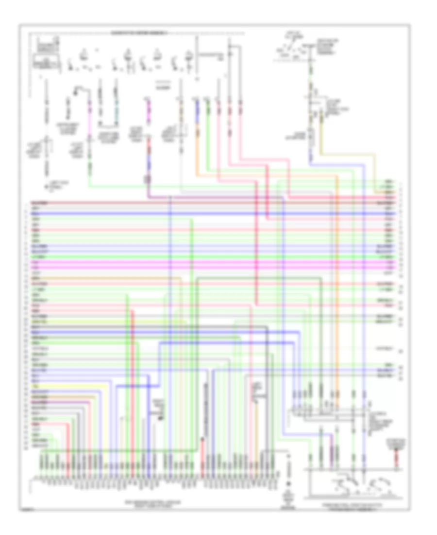
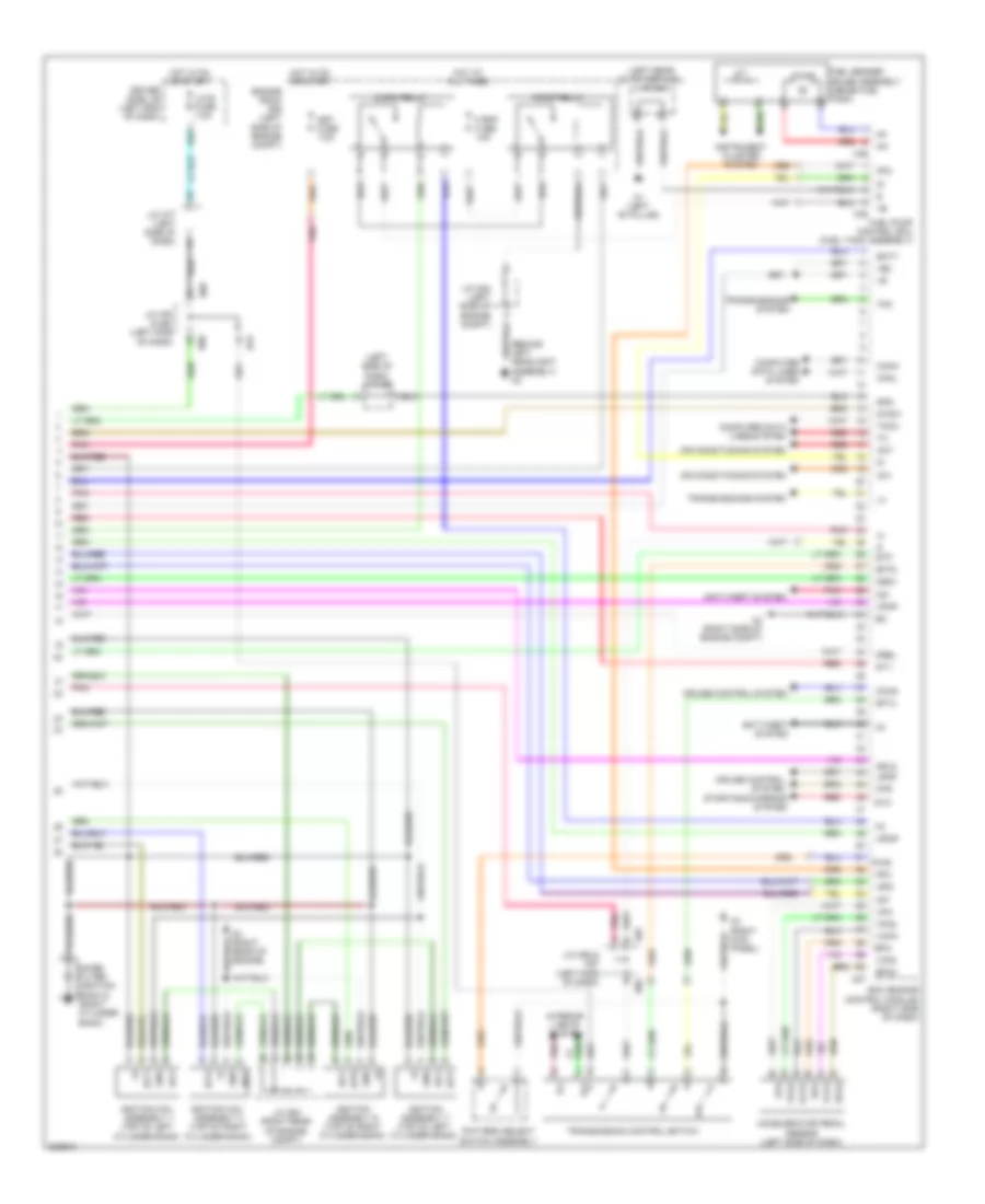
4.6L, Engine Performance Wiring Diagram (7 of 7) for Toyota Sequoia Limited 2010
List of elements for 4.6L, Engine Performance Wiring Diagram (7 of 7) for Toyota Sequoia Limited 2010:
- (fuel tank assembly) fuel pump control ecu
- (inside fuel tank) fuel sender gauge assembly
- (left side of dash) j/c h80
- +b2
- A2 (behind left headlight assembly)
- A27
- A4 (right side of engine compt)
- Ac1
- Accelerator pedal sensor (left side of dash)
- Act
- Aip
- Aip2
- Air conditioning system
- Anti-theft system
- Arv2
- Batt
- C/opn relay
- Canh
- Canl
- Cchg
- Ccs
- Computer data lines system
- Cruise control system
- D3 (right rear of engine)
- D55
- Driver side j/b (left end of dash)
- Engine control module (ecm) (right side of dash)
- Engine room r/b (left side of engine compt)
- Epa
- Epa2
- F/pmp relay
- Fp-
- Fpc
- Gnd
- H3 (right kick panel)
- H79
- H80
- H86
- H87
- Hot in on or start
- Igf1
- Ignition coil assembly 1 (top of left cylinder bank)
- Ignition coil assembly 4 (top of right cylinder bank)
- Ignition coil assembly 6 (top of right cylinder bank)
- Ignition coil assembly 7 (top of left cylinder bank)
- Igsw
- Igt1
- Igt4
- Igt6
- Igt7
- Ill+
- Ill-
- Imi
- Imo
- Instrument cluster system
- Interior lights system
- J/c a54 (left side of engine compt)
- J/c d54 (right rear of engine compt)
- J/c h77 (left side of dash)
- J/c h79 & h80 (left side of dash)
- J/c h86 & h87 (left side of dash)
- J/c o40 (left rear quarter- panel)
- Lgnd
- Lh-ig fuse 7.5a
- Met fuse 7.5a
- Mpmp
- Mrel
- Noise filter (ignition bank 2) (right cylinder bank)
- O1 (left "b" pillar)
- O35
- O36
- Pnk
- Pump
- Pwr
- Red
- Sftd
- Sftu
- Spd
- St1-
- Sta
- Starting/charging system
- Stp
- Stsw
- Tach
- Tfn
- Transmission control switch
- Transmissions system
- Vcp2
- Vcpa
- Vpa
- Vpa2
- Vpmp
5.7L
5.7L, Engine Performance Wiring Diagram (1 of 7) for Toyota Sequoia Limited 2010
List of elements for 5.7L, Engine Performance Wiring Diagram (1 of 7) for Toyota Sequoia Limited 2010:
- (right front of engine) throttle body motor assembly
- (right side of engine compt) mass air flow meter
- (top of
- (top of left cylinder bank) fuel injector 1
- (top of left cylinder bank) fuel injector 3
- (top of left cylinder bank) fuel injector 5
- (top of right cylinder bank) fuel injector 2
- (top of right cylinder bank) fuel injector 4
- (top of right cylinder bank) fuel injector 8
- A1a+
- A1a-
- A2a+
- A2a-
- Air fuel ratio sensor (bank 1 sensor 1)
- Air fuel ratio sensor (bank 2 sensor 1)
- D1 (left rear of engine)
- D2 (right rear of engine)
- D56
- E2g
- Ecm (engine control module) (right side of dash)
- Ekn2
- Ekn3
- Ekn4
- Eknk
- Eta
- Etha
- Ethw
- Ev1+
- Ev1-
- Ex1b
- Ex2b
- Fuel injector 6
- Fuel injector 7
- G2-
- Ha1a
- Ha2a
- Ht1b
- Ht2b
- Igf1
- Igf2
- J/c d53 (right rear of engine compt)
- Knk1
- Knk2
- Knk3
- Knk4
- Knock control sensor (bank 2 sensor 1) (top right of engine)
- Left cylinder bank)
- Me01
- Nca
- Ne+
- Ne-
- Nsw
- Nt+
- Nt-
- Ox1b
- Ox2b
- Oxygen sensor (bank 1 sensor 2) (rear of catalytic converter)
- Oxygen sensor (bank 2 sensor 2) (rear of catalytic converter)
- Pnk
- Ppmp
- Psp
- Red
- Right cylinder bank)
- Sp2+
- Sp2-
- Tha
- Tho1
- Tho2
- Thw
- Transmission revolution sensor (turbine) (transmission assembly)
- Vcta
- Vcv1
- Vcv2
- Vta
- Vta1
- Vta2
- Vv1+
- Vv1-
- Vv2+
- Vv2-
5.7L, Engine Performance Wiring Diagram (2 of 7) for Toyota Sequoia Limited 2010
List of elements for 5.7L, Engine Performance Wiring Diagram (2 of 7) for Toyota Sequoia Limited 2010:
- (left front of engine) efi engine coolant temperature sensor
- (left side of engine compt) j/c a54
- (left side of engine) vvt sensor (bank 1 exhaust)
- (left side of engine) vvt sensor (bank 1 intake)
- A/f fuse 15a
- A/f relay
- A/pump fuse 50a
- A2 (behind left headlight assembly)
- Camshaft position sensor (front of left cylinder head)
- Crankshaft position sensor (left side of engine)
- Efi 1 fuse 25a
- Efi main relay
- Engine room j/b (left side of engine compt)
- Ex+
- Ex-
- Hot at all times
- J/c d53 (right rear of engine compt)
- Knock control sensor (bank 1 sensor 1) (top left of engine)
- Knock control sensor (bank 1 sensor 2) (top left of engine)
- Knock control sensor (bank 2 sensor 2) (top right of engine)
- Ne+
- Ne-
- Purge vsv (top left of engine)
- Red
- Vc2
- Vvl+
- Vvl-
5.7L, Engine Performance Wiring Diagram (3 of 7) for Toyota Sequoia Limited 2010
List of elements for 5.7L, Engine Performance Wiring Diagram (3 of 7) for Toyota Sequoia Limited 2010:
- (fuel tank assembly) fuel tank solenoid valve
- (left rear of engine) d1
- (left side of engine compt) air injection control driver (bank 2)
- (right rear of engine) d2
- (right side of engine) air pump assembly (bank 2)
- (right side of engine) vvt sensor (bank 2 exhaust)
- (right side of engine) vvt sensor (bank 2 intake)
- (under left rear of vehicle) q1
- +b2
- Acis
- Airp
- Arp2
- Bat2
- Camshaft timing oil control valve (bank 1 exhaust) (left front of engine)
- Camshaft timing oil control valve (bank 1 intake) (top left of engine)
- Camshaft timing oil control valve (bank 2 exhaust) (right front of engine)
- Camshaft timing oil control valve (bank 2 intake) (top right of engine)
- D33
- D34
- D56
- Di2
- E03
- Ecm (engine control module) (right side of dash)
- Engine room r/b (left side of engine compt)
- Ev2+
- Ev2-
- Ex+
- Ex-
- F/pmp vsv relay (5.7l flex fuel)
- Fpcr
- Oc1+
- Oc1-
- Oc2+
- Oc2-
- Oe1+
- Oe1-
- Oe2+
- Oe2-
- Pnk
- Prg
- Red
- Sip2
- Siv2
- Vc2
- Vp2
- Vsc (acis) (top left rear of engine)
- Vv2
- Vvr+
- Vvr-
5.7L, Engine Performance Wiring Diagram (4 of 7) for Toyota Sequoia Limited 2010
List of elements for 5.7L, Engine Performance Wiring Diagram (4 of 7) for Toyota Sequoia Limited 2010:
- (left rear of engine) air switching valve (bank 1)
- (left rear of engine) d1
- (left side of engine compt) air injection control driver (bank 1)
- (right front of engine) air pump assembly (bank 1)
- (right front of engine) power steering oil pressure sensor
- (right rear of engine) air switching valve (bank 2)
- (right rear of engine) d3
- +bl
- Aip
- Aip2
- Batt
- D3 (right rear of engine)
- D31
- D32
- E22
- Gnd
- Gndl
- Igf2
- Ignition coil assembly 2 (top of right cylinder bank)
- Ignition coil assembly 3 (top of left cylinder bank)
- Ignition coil assembly 5 (top of left cylinder bank)
- Ignition coil assembly 8 (top of right cylinder bank)
- Igt2
- Igt3
- Igt5
- Igt8
- J/c d54 (right rear of engine compt)
- Noise filter (ignition bank 1) (left cylinder bank)
- Pnk
- Psp
- Red
- Sip
- Siv
- Vc2
5.7L, Engine Performance Wiring Diagram (5 of 7) for Toyota Sequoia Limited 2010
List of elements for 5.7L, Engine Performance Wiring Diagram (5 of 7) for Toyota Sequoia Limited 2010:
- (right rear of engine) d2
- (under rear of vehicle) canister pump module
- 5.7l flex fuel
- A/pump fuse 50a
- A48
- A53
- Canister pressure sensor
- D41
- D42
- Efi 2 fuse 10a
- Electronically controlled transmission solenoid (transmission assembly)
- Engine room j/b (left side of engine compt)
- Engine room r/b (left side of engine compt)
- Etcs fuse 10a
- Hot at all times
- Hot in on or start
- Ign fuse 10a
- Inj fuse 10a
- J/c a48 & a49 (left end of dash) a49
- J/c a52 & a53 (left end of dash) a52
- J/c a53 & a52 (left end of dash) a52
- Leak detection pump
- Ot+
- Ot-
- Ot2+
- Ot2-
- Pnk
- Red
- Sl1+
- Sl1-
- Sl2+
- Sl2-
- Slt+
- Slt-
- Slu+
- Slu-
- Stop fuse 15a
- Stop light switch (left side of dash)
- Transmission revolution sensor (counter gear) (transmission assembly)
- Vent valve
5.7L, Engine Performance Wiring Diagram (6 of 7) for Toyota Sequoia Limited 2010
List of elements for 5.7L, Engine Performance Wiring Diagram (6 of 7) for Toyota Sequoia Limited 2010:
- (left kick panel) h1
- (left rear of engine) d1
- (right rear of engine) d2
- +bm
- A50
- A51
- A61
- Acc
- Aid2
- Aidi
- Airv
- Alt
- Buzzer
- Canh
- Canl
- Combination meter assembly
- Computer data lines system
- D2 (right rear of engine)
- D55
- D56 ht1b
- Dim
- Diode (starting)
- E01
- E02
- E04
- E05
- Ecm (engine control module) (right side of dash)
- Ge01
- Ha1a
- Ha2a
- Hot at all times
- Ht2b
- Ignition or starter switch assembly
- Igt1
- Igt2
- Igt3
- Igt4
- Igt5
- Igt6
- Igt7
- Igt8
- Instrument cluster system
- J/b 3 (right end of dash)
- J/c a50 & a51 (right kick panel) a51
- J/c d55 & a61 (right rear of engine compt) d55
- J/c h77 (left side of dash)
- J/c h83 (right side of dash)
- J/c h85 (left side of dash)
- Lcd (sequential shift)
- Lock
- Malfunction ind
- Off
- Park/neutral position switch (transmission assembly)
- Pnk
- Power circuit
- Red
- Sl1+
- Sl1-
- Sl2+
- Sl2-
- Slt+
- Slt-
- Slu+
- Slu-
- Star
- Start
- Starting/ charging system
- Starting/charging system
5.7L, Engine Performance Wiring Diagram (7 of 7) for Toyota Sequoia Limited 2010
List of elements for 5.7L, Engine Performance Wiring Diagram (7 of 7) for Toyota Sequoia Limited 2010:
- (behind left headlight assembly) a2
- (left rear quarterpanel) j/c o40
- (left side of dash) j/c h80
- +b2
- A27
- A4 (right side of engine compt)
- Ac1
- Accelerator pedal sensor (left side of dash)
- Act
- Aip
- Aip2
- Air conditioning system
- Anti-theft system
- Arv2
- Batt
- C/opn relay
- Canh
- Canl
- Cchg
- Ccs
- Computer data lines system
- Cruise control system
- D3 (right rear of engine)
- D55
- Driver side j/b (left end of dash)
- Ecm (engine control module) (right side of dash)
- Engine room r/b (left side of engine compt)
- Epa
- Epa2
- F/pmp fuse 15a
- F/pmp relay
- Fp-
- Fpc
- Fuel pump control ecu (fuel tank assembly)
- Fuel sender gauge assembly (inside fuel tank)
- Gnd
- H3 (right kick panel)
- H79
- H80
- H86
- H87
- Hot at all times
- Hot in on or start
- Igf1
- Ignition assembly 6 (top of right cylinder bank)
- Ignition assembly 7 (top of left cylinder bank)
- Ignition coil assembly 1 (top of left cylinder bank)
- Ignition coil assembly 4 (top of right cylinder bank)
- Igsw
- Igt1
- Igt4
- Igt6
- Igt7
- Ill+
- Ill-
- Imi
- Imo
- Instrument cluster system
- Interior lights system
- J/c a54 (left side of engine compt)
- J/c d54 (right rear of engine compt)
- J/c h77 (left side of dash)
- J/c h79 & h80 (left side of dash)
- J/c h86 & h87 (left side of dash)
- Lgnd
- Lh-ig fuse 7.5a
- Met fuse 7.5a
- Mpmp
- Mrel
- Noise filter (ignition bank 2) (right cylinder bank)
- O1 (left "b" pillar)
- O35
- O36
- Pattern select switch assembly
- Pnk
- Pump
- Pwr
- Red
- Sftd
- Sftu
- Spd
- St1-
- Sta
- Starting/charging system
- Stp
- Stsw
- Tach
- Tfn
- Transmission control switch
- Transmissions system
- Vcp2
- Vcpa
- Vpa
- Vpa2
- Vpmp
5.7L FLEX FUEL
5.7L Flex Fuel, Engine Performance Wiring Diagram (1 of 7) for Toyota Sequoia Limited 2010
List of elements for 5.7L Flex Fuel, Engine Performance Wiring Diagram (1 of 7) for Toyota Sequoia Limited 2010:
- (right front of engine) throttle body motor assembly
- (right side of engine compt) mass air flow meter
- (top of
- (top of left cylinder bank) fuel injector 1
- (top of left cylinder bank) fuel injector 3
- (top of left cylinder bank) fuel injector 5
- (top of right cylinder bank) fuel injector 2
- (top of right cylinder bank) fuel injector 4
- (top of right cylinder bank) fuel injector 8
- A1a+
- A1a-
- A2a+
- A2a-
- Air fuel ratio sensor (bank 1 sensor 1)
- Air fuel ratio sensor (bank 2 sensor 1)
- D1 (left rear of engine)
- D2 (right rear of engine)
- D56
- E2g
- Ecm (engine control module) (right side of dash)
- Ekn2
- Ekn3
- Ekn4
- Eknk
- Eta
- Etha
- Ethw
- Ev1+
- Ev1-
- Ex1b
- Ex2b
- Fuel injector 6
- Fuel injector 7
- G2-
- Ha1a
- Ha2a
- Ht1b
- Ht2b
- Igf1
- Igf2
- J/c d53 (right rear of engine compt)
- Knk1
- Knk2
- Knk3
- Knk4
- Knock control sensor (bank 2 sensor 1) (top right of engine)
- Left cylinder bank)
- Me01
- Nca
- Ne+
- Ne-
- Nsw
- Nt+
- Nt-
- Ox1b
- Ox2b
- Oxygen sensor (bank 1 sensor 2) (rear of catalytic converter)
- Oxygen sensor (bank 2 sensor 2) (rear of catalytic converter)
- Pnk
- Ppmp
- Psp
- Red
- Right cylinder bank)
- Sp2+
- Sp2-
- Tha
- Tho1
- Tho2
- Thw
- Transmission revolution sensor (turbine) (transmission assembly)
- Vcta
- Vcv1
- Vcv2
- Vta
- Vta1
- Vta2
- Vv1+
- Vv1-
- Vv2+
- Vv2-
5.7L Flex Fuel, Engine Performance Wiring Diagram (2 of 7) for Toyota Sequoia Limited 2010
List of elements for 5.7L Flex Fuel, Engine Performance Wiring Diagram (2 of 7) for Toyota Sequoia Limited 2010:
- (left front of engine) efi engine coolant temperature sensor
- (left side of engine compt) j/c a54
- (left side of engine) vvt sensor (bank 1 exhaust)
- (left side of engine) vvt sensor (bank 1 intake)
- A/f fuse 15a
- A/f relay
- A/pump fuse 50a
- A2 (behind left headlight assembly)
- Camshaft position sensor (front of left cylinder head)
- Crankshaft position sensor (left side of engine)
- Efi 1 fuse 25a
- Efi main relay
- Engine room j/b (left side of engine compt)
- Ex+
- Ex-
- Hot at all times
- J/c d53 (right rear of engine compt)
- Knock control sensor (bank 1 sensor 1) (top left of engine)
- Knock control sensor (bank 1 sensor 2) (top left of engine)
- Knock control sensor (bank 2 sensor 2) (top right of engine)
- Ne+
- Ne-
- Purge vsv (top left of engine)
- Red
- Vc2
- Vvl+
- Vvl-
5.7L Flex Fuel, Engine Performance Wiring Diagram (3 of 7) for Toyota Sequoia Limited 2010
List of elements for 5.7L Flex Fuel, Engine Performance Wiring Diagram (3 of 7) for Toyota Sequoia Limited 2010:
- (fuel tank assembly) fuel tank solenoid valve
- (left rear of engine) d1
- (left side of engine compt) air injection control driver (bank 2)
- (right rear of engine) d2
- (right side of engine) air pump assembly (bank 2)
- (right side of engine) vvt sensor (bank 2 exhaust)
- (right side of engine) vvt sensor (bank 2 intake)
- (under left rear of vehicle) q1
- +b2
- Acis
- Airp
- Arp2
- Bat2
- Camshaft timing oil control valve (bank 1 exhaust) (left front of engine)
- Camshaft timing oil control valve (bank 1 intake) (top left of engine)
- Camshaft timing oil control valve (bank 2 exhaust) (right front of engine)
- Camshaft timing oil control valve (bank 2 intake) (top right of engine)
- D33
- D34
- D56
- Di2
- E03
- Ecm (engine control module) (right side of dash)
- Engine room r/b (left side of engine compt)
- Ev2+
- Ev2-
- Ex+
- Ex-
- F/pmp vsv relay (5.7l flex fuel)
- Fpcr
- Oc1+
- Oc1-
- Oc2+
- Oc2-
- Oe1+
- Oe1-
- Oe2+
- Oe2-
- Pnk
- Prg
- Red
- Sip2
- Siv2
- Vc2
- Vp2
- Vsc (acis) (top left rear of engine)
- Vv2
- Vvr+
- Vvr-
5.7L Flex Fuel, Engine Performance Wiring Diagram (4 of 7) for Toyota Sequoia Limited 2010
List of elements for 5.7L Flex Fuel, Engine Performance Wiring Diagram (4 of 7) for Toyota Sequoia Limited 2010:
- (left rear of engine) air switching valve (bank 1)
- (left rear of engine) d1
- (left side of engine compt) air injection control driver (bank 1)
- (right front of engine) air pump assembly (bank 1)
- (right front of engine) power steering oil pressure sensor
- (right rear of engine) air switching valve (bank 2)
- (right rear of engine) d3
- +bl
- Aip
- Aip2
- Batt
- D3 (right rear of engine)
- D31
- D32
- E22
- Gnd
- Gndl
- Igf2
- Ignition coil assembly 2 (top of right cylinder bank)
- Ignition coil assembly 3 (top of left cylinder bank)
- Ignition coil assembly 5 (top of left cylinder bank)
- Ignition coil assembly 8 (top of right cylinder bank)
- Igt2
- Igt3
- Igt5
- Igt8
- J/c d54 (right rear of engine compt)
- Noise filter (ignition bank 1) (left cylinder bank)
- Pnk
- Psp
- Red
- Sip
- Siv
- Vc2
5.7L Flex Fuel, Engine Performance Wiring Diagram (5 of 7) for Toyota Sequoia Limited 2010
List of elements for 5.7L Flex Fuel, Engine Performance Wiring Diagram (5 of 7) for Toyota Sequoia Limited 2010:
- (right rear of engine) d2
- (under rear of vehicle) canister pump module
- 5.7l flex fuel
- A/pump fuse 50a
- A48
- A53
- Canister pressure sensor
- D41
- D42
- Efi 2 fuse 10a
- Electronically controlled transmission solenoid (transmission assembly)
- Engine room j/b (left side of engine compt)
- Engine room r/b (left side of engine compt)
- Etcs fuse 10a
- Hot at all times
- Hot in on or start
- Ign fuse 10a
- Inj fuse 10a
- J/c a48 & a49 (left end of dash) a49
- J/c a52 & a53 (left end of dash) a52
- J/c a53 & a52 (left end of dash) a52
- Leak detection pump
- Ot+
- Ot-
- Ot2+
- Ot2-
- Pnk
- Red
- Sl1+
- Sl1-
- Sl2+
- Sl2-
- Slt+
- Slt-
- Slu+
- Slu-
- Stop fuse 15a
- Stop light switch (left side of dash)
- Transmission revolution sensor (counter gear) (transmission assembly)
- Vent valve
5.7L Flex Fuel, Engine Performance Wiring Diagram (6 of 7) for Toyota Sequoia Limited 2010
List of elements for 5.7L Flex Fuel, Engine Performance Wiring Diagram (6 of 7) for Toyota Sequoia Limited 2010:
- (left kick panel) h1
- (left rear of engine) d1
- (right rear of engine) d2
- +bm
- A50
- A51
- A61
- Acc
- Aid2
- Aidi
- Airv
- Alt
- Buzzer
- Canh
- Canl
- Combination meter assembly
- Computer data lines system
- D2 (right rear of engine)
- D55
- D56 ht1b
- Dim
- Diode (starting)
- E01
- E02
- E04
- E05
- Ecm (engine control module) (right side of dash)
- Ge01
- Ha1a
- Ha2a
- Hot at all times
- Ht2b
- Ignition or starter switch assembly
- Igt1
- Igt2
- Igt3
- Igt4
- Igt5
- Igt6
- Igt7
- Igt8
- Instrument cluster system
- J/b 3 (right end of dash)
- J/c a50 & a51 (right kick panel) a51
- J/c d55 & a61 (right rear of engine compt) d55
- J/c h77 (left side of dash)
- J/c h83 (right side of dash)
- J/c h85 (left side of dash)
- Lcd (sequential shift)
- Lock
- Malfunction ind
- Off
- Park/neutral position switch (transmission assembly)
- Pnk
- Power circuit
- Red
- Sl1+
- Sl1-
- Sl2+
- Sl2-
- Slt+
- Slt-
- Slu+
- Slu-
- Star
- Start
- Starting/ charging system
- Starting/charging system
5.7L Flex Fuel, Engine Performance Wiring Diagram (7 of 7) for Toyota Sequoia Limited 2010
List of elements for 5.7L Flex Fuel, Engine Performance Wiring Diagram (7 of 7) for Toyota Sequoia Limited 2010:
- (behind left headlight assembly) a2
- (left rear quarterpanel) j/c o40
- (left side of dash) j/c h80
- +b2
- A27
- A4 (right side of engine compt)
- Ac1
- Accelerator pedal sensor (left side of dash)
- Act
- Aip
- Aip2
- Air conditioning system
- Anti-theft system
- Arv2
- Batt
- C/opn relay
- Canh
- Canl
- Cchg
- Ccs
- Computer data lines system
- Cruise control system
- D3 (right rear of engine)
- D55
- Driver side j/b (left end of dash)
- Ecm (engine control module) (right side of dash)
- Engine room r/b (left side of engine compt)
- Epa
- Epa2
- F/pmp fuse 15a
- F/pmp relay
- Fp-
- Fpc
- Fuel pump control ecu (fuel tank assembly)
- Fuel sender gauge assembly (inside fuel tank)
- Gnd
- H3 (right kick panel)
- H79
- H80
- H86
- H87
- Hot at all times
- Hot in on or start
- Igf1
- Ignition assembly 6 (top of right cylinder bank)
- Ignition assembly 7 (top of left cylinder bank)
- Ignition coil assembly 1 (top of left cylinder bank)
- Ignition coil assembly 4 (top of right cylinder bank)
- Igsw
- Igt1
- Igt4
- Igt6
- Igt7
- Ill+
- Ill-
- Imi
- Imo
- Instrument cluster system
- Interior lights system
- J/c a54 (left side of engine compt)
- J/c d54 (right rear of engine compt)
- J/c h77 (left side of dash)
- J/c h79 & h80 (left side of dash)
- J/c h86 & h87 (left side of dash)
- Lgnd
- Lh-ig fuse 7.5a
- Met fuse 7.5a
- Mpmp
- Mrel
- Noise filter (ignition bank 2) (right cylinder bank)
- O1 (left "b" pillar)
- O35
- O36
- Pattern select switch assembly
- Pnk
- Pump
- Pwr
- Red
- Sftd
- Sftu
- Spd
- St1-
- Sta
- Starting/charging system
- Stp
- Stsw
- Tach
- Tfn
- Transmission control switch
- Transmissions system
- Vcp2
- Vcpa
- Vpa
- Vpa2
- Vpmp
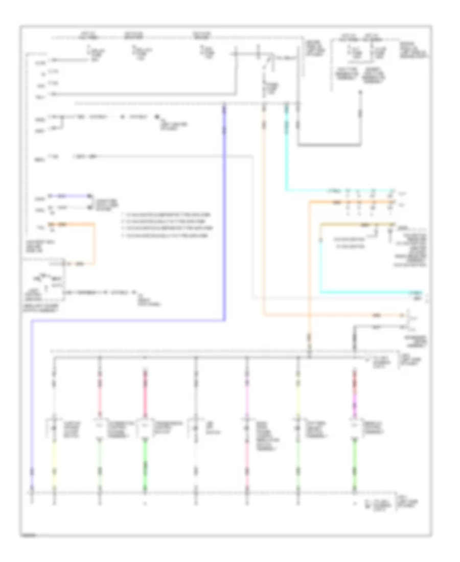
EXTERIOR LIGHTS
Backup Lamps Wiring Diagram for Toyota Sequoia Limited 2010
List of elements for Backup Lamps Wiring Diagram for Toyota Sequoia Limited 2010:
- (left side of rear bumper)
- B/up
- Back up light
- Backup light relay (left side of dash)
- Bk/up lp fuse 10a
- D55
- D65
- Driver side j/b (left end of dash)
- H2 (left center of dash)
- Hot in on or start
- J/c h77 (left side of dash)
- J/c h80 (left side of dash)
- J/c h83 (right side of dash)
- J/c o40 (left rear quarterpanel)
- J/c v19 & v20 (tailgate assembly)
- J/c v19 (tailgate assembly)
- Left rear combination light assembly
- Lh ig fuse 7.5a
- O1 (left "b" pillar)
- Park/ neutral position switch (transmission assembly)
- Red
- Right rear combination light assembly
- Trailer socket
- V19
- W/ trailer socket 7 pin type & 4 pin type
Exterior Lamps Wiring Diagram (1 of 2) for Toyota Sequoia Limited 2010
List of elements for Exterior Lamps Wiring Diagram (1 of 2) for Toyota Sequoia Limited 2010:
- (except usa) tail ind
- (left center of dash) h2
- (left end of dash) j/c a48 & a49
- (left side of dash) j/c h86 & h87
- (left side of dash) stop light switch
- (right kick panel) j/c a50 & a51
- A1 (behind left headlight assembly)
- A27
- A48
- A49
- A50
- A51
- Abs & traction actuator assembly (left rear of engine compt)
- Brk relay
- Brk relay 1
- Bsw
- Canh
- Canl
- Center stop light assembly
- Combination meter assembly
- Computer data lines system
- Cruise control system
- Ecm (right side of dash)
- Ecu-b1 fuse 7.5a
- Engine room r/b (left side of engine compt)
- H86
- H87
- Hot at all times
- Hot in on or start
- Ig+
- J/c h85 (left side of dash)
- J/c o40 (left rear quarterpanel)
- J/c v19 & v20 (tailgate assembly)
- Left rear combination light assembly
- Left turn ind
- Left turn signal light & parking light (left headlight assembly)
- License plate assembly
- Met b fuse 5a
- Met fuse 7.5a
- O1 (left "b" pillar)
- O20
- O21
- O22
- O23
- Parking
- Pnk
- Power circuit
- Red
- Right rear combination light assembly
- Right turn ind
- Stop
- Stop fuse 15a
- Stp
- Stp2
- Stpo
- Tail
- Tail/side marker
- Turn
- Turn haz fuse 15a
- V19
- V20
Exterior Lamps Wiring Diagram (2 of 2) for Toyota Sequoia Limited 2010
List of elements for Exterior Lamps Wiring Diagram (2 of 2) for Toyota Sequoia Limited 2010:
- 130a type generator assembly
- A1 (behind left headlight assembly)
- A3 (right side of engine compt)
- Acc
- Acc fuse 7.5a
- Alt fuse 140a
- Altb
- Auto
- B13
- B17
- Becu
- C22
- Canh
- Canl
- Computer data lines system
- D55
- D62
- Dcty
- Dr/lck fuse 25a
- Driver side j/b (left end of dash)
- Drl
- Ecu-ig 1 fuse 7.5a
- Ecu-ig 2 fuse 7.5a
- Engine room j/b (left side of engine compt)
- Except 130a type generator assembly
- Gnd1
- Gnd2
- H2 (left center of dash)
- H3 (right kick panel)
- H79
- H80
- H86
- H87
- Haz
- Hazard warning signal switch assembly
- Head
- Headlight dimmer switch assembly
- Hot at all times
- Hot in on or acc
- Hot in on or start
- Interior lights system
- J/c a49 (left end of dash)
- J/c a52 (left end of dash)
- J/c h77 (left side of dash)
- J/c h79 & h80 (left side of dash)
- J/c h85 (left side of dash)
- J/c h86 & h87 (left side of dash)
- Lcty
- Left
- Left outer rear view mirror assembly (if equipped)
- Left side marker light (left headlight assembly)
- Lh ig fuse 7.5a
- Lh j/b fuse 150a
- Light control switch
- Ltot
- Ltrn
- Main body ecu (driver side j/b)
- Off
- Parking
- Pcty
- Pnk
- Red
- Right
- Right outer rear view mirror assembly (if equipped)
- Right side marker light (right headlight assembly)
- Right turn signal light & parking light (right headlight assembly)
- Rrcy
- Rtot
- Rtrn
- Stin
- Tail
- Tail fuse 15a
- Tail relay
- Trailer tow circuit
- Trly
- Turn
- Turn signal flasher assembly (left end of dash)
- Turn signal switch
- W/ drl
Trailer Tow Wiring Diagram (1 of 2) for Toyota Sequoia Limited 2010
List of elements for Trailer Tow Wiring Diagram (1 of 2) for Toyota Sequoia Limited 2010:
- (left end of dash) j/c a48 & a49
- A2 (behind left headlight assembly)
- A27
- A48
- A49
- Abs & traction actuator assembly (left rear of engine compt)
- B/up
- Backup lamps circuit
- Batt
- Brk
- Brk relay
- Brk relay 1
- Bsw
- Canh
- Canl
- Combination meter assembly
- Computer data lines system
- Cruise control system
- Ecm (right side of dash)
- Engine room r/b (left side of engine compt)
- Gnd
- H2 (left center of dash)
- H86
- H87
- Hot at all times
- Hot in on or start
- Ig+
- J/c a51 (right kick panel)
- J/c a54 (left side of engine compt)
- J/c h85 (left side of dash)
- J/c h87 & h86 (left side of dash)
- J/c o40 (left rear quarterpanel)
- Met fuse 7.5a
- O1 (left "b" pillar)
- Pnk
- Red
- Stop
- Stop fuse 15a
- Stop light switch (left side of dash)
- Stp
- Stpo
- Sttl
- Sttr
- Sub batt fuse 40a
- Sub batt relay (trailer socket 7 pin type & 4 pin type)
- Tail
- Tow brk fuse 30a
- Towing brake controller
- Towing fuse 30a
- Towing haul ind
- Trailer socket (left side of rear bumper)
- Trailer socket 4 pin type
- Trailer socket 7 pin type & 4 pin type
Trailer Tow Wiring Diagram (2 of 2) for Toyota Sequoia Limited 2010
List of elements for Trailer Tow Wiring Diagram (2 of 2) for Toyota Sequoia Limited 2010:
- 130a type generator assembly
- A48
- A49
- A52
- A53
- Alt fuse 140a
- Auto
- B17
- Driver side j/b (left end of dash)
- Ecu ig 1 fuse 7.5a
- Engine room j/b (left side of engine compt)
- Engine room r/b (left side of engine compt)
- Except 130a type generator assembly
- H2 (left center of dash)
- H3 (right kick panel)
- H86
- H87
- Haz
- Hazard warning signal switch assembly
- Head
- Headlight dimmer switch assembly
- Hot at all times
- Hot in on or start
- J/c a48 & a49 (left end of dash)
- J/c a52 & a53 (left end of dash)
- J/c h86 & h87 (left side of dash)
- Left
- Lh j/b fuse 150a
- Light control switch
- Ltot
- Main body ecu (driver side j/b)
- Off
- Pnk
- Red
- Right
- Rtot
- Stin
- Tail
- Tail fuse 15a
- Tail relay
- Tow tail fuse 30a
- Tow tail relay
- Trly
- Turn signal flasher assembly (left end of dash)
- Turn signal switch
GROUND DISTRIBUTION
Ground Distribution Wiring Diagram (1 of 4) for Toyota Sequoia Limited 2010
List of elements for Ground Distribution Wiring Diagram (1 of 4) for Toyota Sequoia Limited 2010:
- (4wd) four wheel drive control ecu
- (left side of engine compt) engine room j/b
- (left side of engine compt) engine room r/b
- (w/o navigation system) radio receiver assembly
- A/f relay
- A1 (behind left headlight assembly)
- A2 (behind left headlight assembly)
- A27
- A29
- A3 (right side of engine compt)
- A4 (right side of engine compt)
- Abs & traction actuator assembly
- Air sus relay
- Back door power
- Brake fluid level warning switch (brake master cylinder reservoir sub assembly)
- Center air bag sensor assembly
- Clearance warning ecu assembly
- Cooling fan motor
- D16
- D28
- Defog relay
- Driver side j/b (left end of dash)
- Ecm
- Efi main relay
- Engine hood security courtesy switch
- Except 4.6l
- F/pmp relay
- Front blower w/ fan motor sub assembly
- Front wiper deicer (wind- shield glass)
- Glove box light assembly
- H14
- H3 (right kick panel)
- H4 (w/ seat position memory) (left side of dash)
- H56
- Headlight cleaner control relay
- Headlight dimmer switch assembly
- I16
- I2 (under center console)
- I20
- I38
- Ig2 relay
- Junction connector a46 (right side of dash)
- Junction connector a54 (left side of engine compt)
- Junction connector h83 (right side of dash)
- Left fog light assembly
- Left headlight assembly (high)
- Left headlight assembly (low)
- Left parking/ turn signal light (left headlight assembly)
- Left side marker light (left headlight assembly)
- Level warning switch assembly
- Navigation receiver assembly
- Noise filter
- Pattern select switch assembly
- Rear washer motor & pump assembly
- Right fog light assembly
- Right headlight assembly (high)
- Right headlight assembly (low)
- Right side marker light (right headlight assembly)
- Right turn signal light & parking light (right headlight assembly)
- Shift lock control ecu sub assembly
- St relay
- Stereo component amplifier assembly
- Stereo component tuner assembly
- Sub batt relay
- Switch assembly
- To curtain air bag cutoff switch (diagram 3 of 4)
- To ground h2 (diagram 2 of 4)
- Trailer socket 7 pin & 4 pin type
- Transmission control switch
- W/ drl
- Window regulator
- Windshield wiper motor assembly
- Windshield wiper switch assembly
- Wireless door lock buzzer
Ground Distribution Wiring Diagram (2 of 4) for Toyota Sequoia Limited 2010
List of elements for Ground Distribution Wiring Diagram (2 of 4) for Toyota Sequoia Limited 2010:
- (if equipped) left vanity light
- (if equipped) right vanity light
- (w/ rear seat entertainment system) television display assembly
- (w/ seat position memory)
- (w/ trailer socket 7 pin & 4 pin type) backup light relay
- 4 wheel drive control switch
- A/c amplifier assembly
- Acc relay
- Accessory meter assembly
- Center air bag sensor assembly
- Cigarette lighter assembly
- Combination meter assembly
- D30
- D62
- Differ- ential lock switch
- Dlc 3
- Door control switch assembly
- Drive monitor switch
- Driver side j/b (left end of dash)
- From ground h3 (diagram 1 of 4)
- H1 (left kick panel)
- H2 (left center of dash)
- H47
- H49
- H56
- H67
- Hazard warning signal switch assembly
- Height control mode select switch
- Height control switch
- I1 (right center of dash)
- I26
- Ig1 1 relay
- Ig1 2 relay
- Ig1 3 relay
- Inner rear view mirror assembly
- Interior dome light switch assembly
- Inverter relay
- Junction connector h84 (right side of dash)
- Junction connector h85 (left side of dash)
- Key interlock solenoid
- Left front door lock assembly
- Left front power window regulator motor assembly
- Left front seat heater switch
- Left outer rear view mirror assembly
- Left rear air bag sensor shield
- Main body ecu
- Multiplex tilt & telescopic ecu
- Navigation receiver assembly
- Nca
- Option connector (glass breakage sensor ecu)
- Outer mirror control ecu assembly
- Outer mirror switch assembly
- P/w relay
- Position memory
- Power back door opener/ closer switch (back door control switch)
- Power steering ecu assembly
- Power window regulator master switch assembly
- Radio receiver assembly (built in type i1 amplifier)
- Right front door lock assembly
- Right front power window regulator motor assembly
- Right front power window regulator switch assembly
- Right front seat heater switch
- Right outer rear view mirror assembly
- Roof console box assembly
- Room light assembly
- Sliding roof control ecu
- Steering sensor
- Suspension control switch
- Tire pressure warning ecu
- Tire pressure warning reset switch
- Towing brake controller
- Turn signal flasher assembly
- Unlock warning switch assembly
- Vsc off switch
- W/ climate control seat
- W/ daytime running light
- W/ outer rear mirror & w/o turn signal light
- W/ seat
- W/ seat position memory
- W/o climate control seat
- W/o seat position memory
Ground Distribution Wiring Diagram (3 of 4) for Toyota Sequoia Limited 2010
List of elements for Ground Distribution Wiring Diagram (3 of 4) for Toyota Sequoia Limited 2010:
- (w/ power back door) power back door unit assembly
- (w/ power rear 2 & stowing function) right fold seat control ecu
- (w/o power back door) back door lock assembly w/ motor
- (w/o rear seat entertainment system) center power outlet socket assembly
- A/c amplifier assembly
- Back door ecu
- Center power point socket assembly
- Center stop light assembly
- Curtain air bag cutoff switch
- From junction connector h83 (diagram 1 of 4)
- Front power point socket assembly
- H24
- Integration control & panel assembly
- Joint connector p22
- Junction connector o39 (left rear quarterpanel)
- Junction connector v19 & v20 (tailgate assembly)
- Junction connector w14 (under front passenger's seat)
- Left fold seat control ecu
- Left rear combination light assembly
- Left rear power seat switch (w/ power rear seat 2 & stowing function)
- Left rear seat heater control sub assembly
- Left rear seat heater switch
- License plate light assembly
- Main switch assembly
- Nca
- O17
- O18
- O19
- O33
- Occupant detection ecu
- P1 (right "b" pillar)
- P14
- P19
- P2 (right quarterpanel)
- Power back door closer switch (back door control switch) (if equipped)
- Power back door unit assembly
- Power slide back door warning buzzer
- Power source control ecu
- Rear a/c control assembly
- Rear blower motor control
- Rear blower w/ fan motor sub assembly
- Rear seat 2 w/ power & stowing function
- Right curtain shield air bag assembly
- Right front lumbar power seat switch
- Right front power seat switch
- Right front seat heater control sub assembly
- Right rear combination light assembly
- Right rear door w/ motor lock assembly
- Right rear power seat switch
- Right rear seat heater control sub assembly
- Right rear seat heater switch
- Right seat back climate control blower
- Right seat cushion climate control blower
- Suspension control ecu
- To junction connector o40 (diagram 4 of 4)
- Transponder key ecu assembly
- V19
- V20
- Voltage inverter assembly
- W/ air suspension
- W/ climate control seat
- W/ electronic modulated air suspension
- W/ power back door
- W/ power seat
- W/ rear seat heater
- W/ stowing function & power rear seat 2
- W/ stowing function & w/ power rear seat 2
- W/ stowing function w/o power rear seat 2
- W/o climate control seat
- W/o power seat
Ground Distribution Wiring Diagram (4 of 4) for Toyota Sequoia Limited 2010
List of elements for Ground Distribution Wiring Diagram (4 of 4) for Toyota Sequoia Limited 2010:
- & 7 pin type
- (5.7l flex fuel) fuel tank solenoid valve assembly
- (w/ 10 way control) left seat variable cushion switch
- (w/ climate control seat) left back seat climate control blower
- (w/ climate control seat) left cushion seat climate control blower
- (w/ climate control seat) left front seat heater control sub assembly
- (w/ seat position memory) left front power seat ecu & switch
- (w/o seat position memory) left front power seat switch
- 4.6l
- A61
- Air fuel ratio sensor (bank 1 sensor 1) shield
- Air fuel ratio sensor (bank 2 sensor 1) shield
- Air injection control driver (bank 1)
- Air injection control driver (bank 2)
- Air pump (bank 1) assembly
- Air pump (bank 2) assembly
- Air switching valve (bank 1)
- Air switching valve (bank 2)
- Canister pump module
- D1 (5.7l & 5.7l flex fuel) (left rear of engine)
- D2 (right rear of engine)
- D3 (right rear of engine)
- D32
- D34
- D45
- D46
- D55
- D56
- Differential vacuum actuator assembly
- Distance control ecu assembly
- Dlc 3
- Door control receiver
- Engine control module (ecm)
- Except 4.6l
- From junction connector o39 (diagram 3 of 4)
- From junction connector v19 & v20 (diagram 3 of 4)
- Fuel pump control ecu assembly
- H54
- H86
- H87
- Height control compressor motor (height control compressor 1)
- Height control exhaust valve (height control compressor 1)
- Height control valve
- Ignition coil assembly 1
- Ignition coil assembly 2
- Ignition coil assembly 3
- Ignition coil assembly 4
- Ignition coil assembly 5
- Ignition coil assembly 6
- Ignition coil assembly 7
- Ignition coil assembly 8
- Junction connector a61 & d55 (right rear of engine compt)
- Junction connector d53 (right rear of engine compt)
- Junction connector h86 & h87 (left side of dash)
- Junction connector o40
- Knock control sensor (bank 1 sensor 1) shield
- Knock control sensor (bank 1 sensor 2) shield
- Knock control sensor (bank 2 sensor 1) shield
- Knock control sensor (bank 2 sensor 2) shield
- Laser radar sensor
- Left fold seat control ecu
- Left front lumbar power seat switch
- Left rear combination light assembly
- Left rear door lock assembly
- O1 (left "b" pillar)
- O2 (left quarterpanel)
- O20
- O21
- O22
- O23
- O33
- O35
- Oxygen sensor (bank 1 sensor 2) shield
- Oxygen sensor (bank 2 sensor 2) shield
- Q1 (under left rear of vehicle)
- Rear power point socket assembly
- Rear window defogger (back door glass)
- Right rear combination light assembly
- Spiral cable sub assembly
- Trailer socket
- Transfer shift actuator assembly
- V12
- W/ stowing function & rear power seat 2
- W/ trailer socket 4 pin type
- X10
HEADLIGHTS
Headlights Wiring Diagram for Toyota Sequoia Limited 2010
List of elements for Headlights Wiring Diagram for Toyota Sequoia Limited 2010:
- (behind left headlight assembly) a1
- (left end of dash) turn signal flasher assembly
- (usa)
- 130a type generator assembly
- A1 (behind left headlight assembly)
- A3 (right side of engine compt)
- A48
- A49
- Acc
- Acc fuse 7.5a
- Alt fuse 140a
- Altb
- Auto
- Automatic light control sensor (center of dash)
- B11
- B13
- B16
- B18
- Becu
- Canh
- Canl
- Cltb
- Clte
- Clts
- Combination meter assembly
- Computer data lines system
- D13
- D62
- Dcty
- Dim
- Dim relay
- Dimmer switch
- Dr/lck fuse 25a
- Driver side j/b (left end of dash)
- Drl
- Ecu-b1 fuse 7.5a
- Ecu-ig 2 fuse 7.5a
- Engine room j/b (left side of engine compt)
- Engine room r/b (left side of engine compt)
- Except 130a type generator assembly
- Ffgo
- Ffog
- Flash
- Fog fuse 15a
- Fog light switch
- Fog relay
- Gnd1
- Gnd2
- H2 (left center of dash)
- H3 (right kick panel)
- Head
- Head ind
- Head lh fuse 15a
- Head ll fuse 15a
- Head relay
- Head rh fuse 15a
- Head rl fuse 15a
- Headlight dimmer switch assembly
- High
- High beam ind
- Hot at all times
- Hot in on or acc
- Hot in on or start
- Hrly
- Ig+
- Interior lights system
- J/c a46 (right side of dash)
- J/c a48 & a49 (left end of dash)
- J/c h85 (left side of dash)
- Lcty
- Left fog light assembly
- Left headlight assembly (high)
- Left headlight assembly (low)
- Lh j/b fuse 150a
- Light control switch
- Low
- Main body ecu (driver side j/b)
- Main fuse 40a
- Met fuse 7.5a
- Met-b fuse 5a
- Off
- Parking brake switch (left side of dash)
- Pcty
- Pkb
- Pnk
- Power circuit
- Red
- Right fog light assem- bly
- Right headlight assembly (high)
- Right headlight assembly (low)
- Rrcy
- Tail
- Tail fuse 15a
- Tail relay
- Trly
- Turn signal flasher assembly (left end of dash)
HORN
Horn Wiring Diagram for Toyota Sequoia Limited 2010
List of elements for Horn Wiring Diagram for Toyota Sequoia Limited 2010:
- Cruise control main switch
- D21
- Driver side j/b (left end of dash)
- Engine room j/b (left side of engine compt)
- H54
- High horn (right front of engine compt)
- Horn
- Horn fuse 10a
- Horn relay
- Horn switch
- Hot at all times
- Low horn (left front of engine compt)
- Main body ecu
- Spiral cable (steering column)
- Steering pad switch assembly
- W/ steering pad
- W/o steering pad
- Z11
- Z12
INSTRUMENT CLUSTER
Instrument Cluster Wiring Diagram (1 of 2) for Toyota Sequoia Limited 2010
List of elements for Instrument Cluster Wiring Diagram (1 of 2) for Toyota Sequoia Limited 2010:
- (front of engine) oil pressure sender/gauge assembly
- 4hi ind
- 4lo ind
- A/d
- A/t oil temp ind
- A/t oil temperature gauge
- A1 (behind left headlight assembly)
- Abs ind
- Auto lsd ind
- Blink
- Brake fluid level warning switch (brake fluid reservoir)
- Brake ind
- Buzzer
- Canh
- Canl
- Center differential lock ind
- Charge ind
- Combination meter assembly
- Computer data lines system
- Cruise ind
- Cruise ind (w/o optitron meter)
- Dim
- Door ind
- Dot matrix lcd (odometer & other information)
- Driver monitor switch
- Driver side seat belt ind
- Engine controls system
- Engine room r/b (left side of engine compt)
- Exterior lights system
- Fuel gauge
- Fuel ind
- Fuel sender gauge assembly (inside fuel tank)
- H1 (left kick panel)
- H2 (left center of dash)
- Head ind (usa) tail ind (except usa)
- Height control
- Height control lo ind
- Height control man ind
- Hi ind height control
- High beam ind
- Hot at all times
- Hot in on or start
- Illumination
- Indicator malfunction
- Info
- Interior lights system
- J/c h85 (left side of dash)
- Lcd (odometer)
- Lcd (sequential shift)
- Left turn ind
- Maint reqd ind
- Met fuse 7.5a
- Met-b fuse 5a
- N ind
- Oil gauge
- Pnk
- Power circuit
- Power steering ind
- Red
- Right turn ind
- Rsca off ind
- Select reset
- Setup
- Slip ind
- Speedometer
- Srs ind
- Starting/charging system
- Tachometer
- Temperature gauge
- Tire pressure ind
- Tow haul ind
- Transmissions system
- Voltmeter
- Vsc off ind
- W/ optitron meter
- W/o optitron meter
- Warning systems
- Washer ind
- Wiper/washer system
Instrument Cluster Wiring Diagram (2 of 2) for Toyota Sequoia Limited 2010
List of elements for Instrument Cluster Wiring Diagram (2 of 2) for Toyota Sequoia Limited 2010:
- (left "b" pillar) left front door courtesy light switch
- (left "c" pillar) left rear door courtesy light switch
- (left side of dash) parking brake switch
- A27
- Abs & traction actuator assembly (left rear of engine compt)
- Acc
- Acc fuse 7.5a
- Accessory meter assembly
- Anti-theft system
- B11
- B14
- Back door ecu (tailgate assembly)
- Back door lock assembly (tailgate assembly)
- Bdcy
- Canh
- Canl
- Clearance warning ecu (right side of dash)
- Computer data lines system
- Courtesy switch
- Ctye
- D56
- D62
- Dcty
- Dome fuse 7.5a
- Driver side j/b (left end of dash)
- Ecu-ig 1 fuse 7.5a
- Engine control module (ecm) (right side of dash)
- Engine room r/b (left side of engine compt)
- H1 (left kick panel)
- H77
- H78
- H79
- H80
- H81
- Hot at all times
- Hot in on or acc
- Hot in on or start
- I16
- Ill+
- Ill-
- Interior lights system
- J/c h77 & h78 (left side of dash)
- J/c h78 (left side of dash)
- J/c h79 & h80 (left side of dash)
- J/c h79 (left side of dash)
- J/c h79, h80 & h81 (left side of dash)
- Lcty
- Lin2
- Main body ecu
- Mhtr
- Mpx1
- Navigation receiver (w/ navigation) (center of dash) radio receiver assembly (w/o navigation)
- Navigation system
- Pcty
- Pkb2
- Pnk
- Red
- Right front door courtesy light switch
- Right rear door courtesy light switch
- Rrcy
- Sp1
- Spd
- Stereo component amplifier (under front passenger's seat)
- Tire pressure warning ecu (right side of dash)
- Tx-
- W/ navigation
- W/ power back door
- W/o navigation
- W/o power back door
INTERIOR LIGHTS
Courtesy Lamps Wiring Diagram (1 of 3) for Toyota Sequoia Limited 2010
List of elements for Courtesy Lamps Wiring Diagram (1 of 3) for Toyota Sequoia Limited 2010:
- (behind center of dash) j/c h88
- (left "b" pillar)
- (left side of dash) j/c h79 & h80
- (left side of dash) j/c h81 & h82
- (right rear quarterpanel) j/c p21
- Acc
- Acc fuse 7.5a
- Altb
- B13
- Becu
- C11
- Can
- Canh
- Canl
- Cann
- Canp
- Cgnd
- Computer data lines system
- D51
- D54
- D62
- Dcty
- Diode (left front door courtesy light)
- Diode (left rear door courtesy light)
- Diode (right front door courtesy light)
- Diode (right rear door courtesy light)
- Dr/lck fuse 25a
- Driver side j/b (left end of dash)
- Ecu ig 2 fuse 7.5a
- Gnd
- Gnd1
- Gnd2
- H2 (left center of dash)
- H77
- H78
- H79
- H80
- H81
- H82
- Hot at all times
- Hot in on or acc
- Hot in on or start
- Ile
- Ill+
- Ill-
- J/c h77 & h78 (left side of dash)
- Lcty
- Left front door courtesy light assembly
- Left front door courtesy light switch
- Left outer rear view mirror assembly
- Left rear door courtesy light assembly
- Left rear door courtesy light switch (left "c" pillar)
- Lswd
- Lswl
- Lswp
- Lswr
- Main body ecu (driver side j/b)
- Mir fuse 15a
- Outer mirror control ecu (w/ memory) (left end of dash)
- Pcty
- Pnk
- Power back door closer switch (back door control switch) (if equipped)
- Puddle light
- Red
- Right front door courtesy light assembly
- Right front door courtesy light switch
- Right outer rear view mirror assembly
- Right rear door courtesy light assembly
- Right rear door courtesy light switch
- Rrcy
- W/ power rear 2 seat & stowing function
- W/o power rear 2 seat w/ stowing function
Courtesy Lamps Wiring Diagram (2 of 3) for Toyota Sequoia Limited 2010
List of elements for Courtesy Lamps Wiring Diagram (2 of 3) for Toyota Sequoia Limited 2010:
- (left side of dash) j/c h85
- Canh
- Canl
- Combination meter assembly
- Computer data lines system
- Dome fuse 7.5a
- Door ind
- Ecu b1 fuse 7.5a
- Engine room r/b (left side of engine compt)
- H1 (left kick panel)
- H2 (left center of dash)
- H60
- H77
- H78
- H88
- Hot at all times
- Hot in on or start
- Ig+
- Ignition key cylinder light
- Interior dome light switch assembly
- Interior illumination light assembly 1
- J/c h77 & h78 (left side of dash)
- J/c h88 & h89 (behind center h89
- Left vanity light (if equipped)
- Met b fuse 5a
- Met fuse 7.5a
- Of dash)
- Off
- Pnk
- Power circuit
- Red
- Right vanity light (if equipped)
- Roof console box assembly
- Transponder key amplifier (steering column)
Courtesy Lamps Wiring Diagram (3 of 3) for Toyota Sequoia Limited 2010
List of elements for Courtesy Lamps Wiring Diagram (3 of 3) for Toyota Sequoia Limited 2010:
- Back door ecu (tailgate assembly)
- Back door lock assembly (tailgate assembly)
- Bdcy
- Becu
- Courtesy switch
- Ctye
- Detection unlock
- Door
- Entertainment system
- Gnd
- H2 (left center of dash)
- J/c o40 (left rear quarterpanel)
- J/c v19 (tailgate assembly)
- Left front door lock assembly (driver's door)
- Left rear door lock assembly (right rear door)
- Lglp
- Lssr
- O1 (left "b" pillar)
- Off
- P1 (right "b" pillar)
- Pnk
- Qcty
- Red
- Right front door lock assembly (front passenger's door)
- Right rear door w/ mirror lock assembly (left rear door)
- Room light assembly 1
- Room light assembly 2
- Sig
- Unlock detection
- W/ power back door
- W/ rear seat entertainment system
- W/o power back door
- W/o rear seat
Instrument Illumination Wiring Diagram (1 of 3) for Toyota Sequoia Limited 2010
List of elements for Instrument Illumination Wiring Diagram (1 of 3) for Toyota Sequoia Limited 2010:
- 130a type generator assembly
- Acc
- Acc fuse 7.5a
- Accessory meter assembly
- Alt fuse 140a
- Altb
- Auto
- B13
- Back door power window regulator switch assembly
- Becu
- Canh
- Canl
- Computer data lines system
- Curtain air bag cutoff switch
- D57
- D62
- Dr/lck fuse 25a
- Driver side j/b (left end of dash)
- E10
- Ecu ig 2 fuse 7.5a
- Engine room j/b (left side of engine compt)
- Except 130a type generator assembly
- Gnd1
- Gnd2
- H2 (left center of dash)
- H3 (right kick panel)
- Head
- Headlight dimmer switch assembly
- Hot at all times
- Hot in on or acc
- Hot in on or start
- I20
- I24
- I26
- I27
- Ill+
- Ill-
- Integration control & panel assembly
- J/b 4 (left side of dash)
- J/b 5 (left side of dash)
- Lh-j/b fuse 150a
- Light control switch
- Main body ecu (driver side j/b)
- Navigation receiver (w/ navigation) (center of dash) radio receiver assembly (w/o navigation)
- Off
- Panel fuse 7.5a
- Pattern select switch assembly
- Pnk
- Rear a/c control assembly
- Red
- Swg
- Switch
- Tail
- Tail relay
- To j/b 4 (diagram 2 of 3)
- To j/b 5 (diagram 2 of 3)
- Transmission control switch
- Trly
- Vsc off
- W/ navigation
- W/ navigation & built-in type amplifier
- W/ navigation & separate type amplifier
- W/o navigation
- W/o navigation & built-in type amplifier
- W/o navigation & separate type amplifier
Instrument Illumination Wiring Diagram (2 of 3) for Toyota Sequoia Limited 2010
List of elements for Instrument Illumination Wiring Diagram (2 of 3) for Toyota Sequoia Limited 2010:
- 4wd control switch
- Acc ind
- Auto/off ind
- Differential lock switch
- Drive monitor switch
- From j/b 4 (diagram 1 of 3)
- From j/b 5 (diagram 1 of 3)
- Glove box light assembly
- Gnd
- H3 (right kick panel)
- H54
- Hazard warning signal switch assembly
- Ill+
- Ill-
- Ind voice
- Integration control & panel assembly (w/ steering a/c switch)
- Interior dome light switch assembly
- Interior illumination light assembly 1
- J/b 4 (left side of dash)
- J/b 5 (left side of dash)
- Left front seat heater switch
- Left steering switch
- Mode ind
- Off
- Outer rear view mirror w/ turn signal light
- Outer rear view mirror w/o turn signal light
- Pnk
- Red
- Right front seat heater switch
- Right steering switch
- Seek ind
- Spiral cable (h54: steering column)
- Steering pad switch assembly
- Tel ind
- Temp ind
- Volume ind
- W/ climate control seat
- W/o climate control seat
- Z12
Instrument Illumination Wiring Diagram (3 of 3) for Toyota Sequoia Limited 2010
List of elements for Instrument Illumination Wiring Diagram (3 of 3) for Toyota Sequoia Limited 2010:
- & stowing function
- (left side of dash) j/c h85
- A/d
- Canh
- Canl
- Combination meter assembly
- Computer data lines system
- Ecu b1 fuse 7.5a
- Engine room r/b (left side of engine compt)
- H2 (left center of dash)
- Headlight cleaner switch assembly
- Height control mode select switch
- Height control switch
- Hot at all times
- Hot in on or start
- If equipped
- Ig+
- Ill+
- Ill-
- Illumination (except optitron meter)
- Illumination (w/ optitron
- J/b 6 (right end of dash)
- J/b 7 (under center console)
- J/c o39 (left rear quarterpanel)
- J/c o40 (left rear quarterpanel)
- J/c p21 (right rear quarterpanel)
- Left rear power seat switch
- Left rear seat heater switch
- Light control rheostat
- Met b fuse 5a
- Met fuse 7.5a
- Meter)
- O1 (left "b" pillar)
- Outer mirror switch assembly 2
- Outer rear view mirror w/ turn signal light
- P1 (right "b" pillar)
- Pnk
- Power back door opener/ closer switch (back door control switch)
- Power circuit
- Red
- Rhig
- Right rear power seat switch
- Right rear seat heater switch
- Solid state
- Suspension control switch
- Tail cancel
- W/ power back door
- W/ power rear 2 seat
- W/ rear seat heater
- W/ seat position memory
- W/o rear seat heater
MEMORY SYSTEMS
Memory Mirrors Wiring Diagram for Toyota Sequoia Limited 2010
List of elements for Memory Mirrors Wiring Diagram for Toyota Sequoia Limited 2010:
- (left kick panel) h1
- Acc
- Acc fuse 7.5a
- Can
- Canh
- Canl
- Cann
- Canp
- Cgnd
- Computer data lines system
- D54
- Defogger system
- Driver side j/b (left end of dash)
- Ec+
- Ec-
- Exterior lights system
- Gnd
- H1 (left kick panel)
- H77
- H78
- Hot at all times
- Hot in on or acc
- Hsrl
- Hsrr
- Hssr
- Interior lights system
- J/c h77 & h78 (left side of dash)
- J/c h79 (left side of dash)
- J/c h84 (right side of dash)
- J/c h85 (left side of dash)
- Left outer rear view mirror assembly
- Lp+
- Lp-
- M+l
- M+r
- Main body ecu (driver side j/b)
- Mhl
- Mhr
- Mir fuse 15a
- Mirb
- Mire
- Mirror heater
- Mirrors heater
- Mirrors system
- Mirs
- Mr+
- Mr-
- Mry
- Msw
- Mswe
- Mvl
- Mvr
- Outer mirror control ecu (left end of dash)
- Outer mirror switch assembly
- Outer mirror switch assembly 2
- Paddle light
- Pnk
- Red
- Ret
- Right outer rear view mirror assembly
- Seat memory switch
- Set
- Turn lamp
- Vsr
- Vsrl
- Vssr
Memory Power Tilt & Power Telescopic Wiring Diagram for Toyota Sequoia Limited 2010
List of elements for Memory Power Tilt & Power Telescopic Wiring Diagram for Toyota Sequoia Limited 2010:
- B13
- Can
- Canh
- Canl
- Cgnd
- Computer data lines system
- D14
- D34
- D56
- Driver side j/b (left end of dash)
- Ecu-b1 fuse 7.5a
- Ecu-ig 1 fuse 7.5a
- Ecub
- Engine room r/b (left side of engine compt)
- Gnd
- H2 (left center of dash)
- Headlight dimmer switch assembly
- Hot at all times
- Hot in on or start
- J/c h79 (left side of dash)
- Mry
- Msw
- Mswe
- Multiplex tilt & telescopic ecu (steering column assembly)
- Outer mirror control ecu (left end of dash)
- Pnk
- Power tilt motor (steering column assembly)
- Red
- Seat memory switch
- Set
- Telescopic motor
- Telescopic sensor
- Telescopic shrink
- Telescopic stretch
- Tem+
- Tem-
- Tes
- Ti & te fuse 15a
- Tilt & telescopic switch
- Tilt down
- Tilt motor
- Tilt sensor
- Tilt up
- Tim+
- Tim-
- Tim- tim+
- Tis
- Vce
- Vci
Memory Seat Wiring Diagram for Toyota Sequoia Limited 2010
List of elements for Memory Seat Wiring Diagram for Toyota Sequoia Limited 2010:
- (left "b" pillar) o1
- B13
- C10
- C11
- Can
- Canh
- Canl
- Cgnd
- Computer data lines system
- Csnf
- Csnr
- Driver side j/b (left end of dash)
- Ecu-b1 fuse 7.5a
- Ecu-ig 1 fuse 7.5a
- Engine room r/b (left side of engine compt)
- Fr p/seat lh fuse 30a
- Frv+
- Frv-
- Gnd
- Hot at all times
- Hot in on or start
- Left front lumbar power seat switch
- Left front lumbar support forward/ back motor assembly (driver's seat back)
- Left front power seat cushion control motor assembly (under driver's seat)
- Left front power seat ecu & switch
- Left front power seat reclining position motor assembly (driver's seat back)
- Left front power seat slide position motor assembly (under driver's seat)
- Left power seat lift position motor assembly (under driver's seat)
- Left power seat vertical position motor assembly (under driver's seat)
- Left seat variable cushion switch
- Lft+
- Lft-
- Mry
- Mswe
- O1 (left "b" pillar)
- Outer mirror control ecu (left end of dash)
- Pnk
- Rcl+
- Rcl-
- Red
- Seat memory switch
- Set
- Sld+
- Sld-
- Sysb
- X10
- X11
NAVIGATION
Navigation Wiring Diagram, with Built-in Amplifier for Toyota Sequoia Limited 2010
List of elements for Navigation Wiring Diagram, with Built-in Amplifier for Toyota Sequoia Limited 2010:
- (w/ sdars) antenna
- Acc
- Acc fuse 7.5a
- Ali
- Alo
- Ant
- Antenna
- Antenna amplifier (right center of dash)
- Ari
- Aro
- Asgn
- Auxg
- Auxi
- Auxo
- B11
- Ca+
- Cb+
- Cgnd
- Cv+
- Cv-
- D55
- Driver side j/b (left end of dash)
- Engine room r/b (left side of engine compt)
- Fl+
- Fl-
- Fr+
- Fr-
- Gnd
- Gps antenna
- H107
- H114
- Hot at all times
- Hot in on or acc
- Hot in on or start
- I1 (right center of dash)
- I26
- I27
- I28
- Ill+
- Ill-
- Instrument cluster system
- Interior lights system
- J/c h77 (w/ rear view monitor) (left side of dash)
- J/c h80 (w/ rear view monitor) (left side of dash)
- J/c h83 (w/ rear view monitor) (right side of dash)
- Left front speaker assembly 1
- Left front speaker assembly 2
- Left quarter side speaker assembly
- Left rear speaker assembly 2
- Lh ig fuse 7.5a
- Multi-media interface ecu (center right of dash)
- Navigation receiver (center of dash)
- Nca
- Park/ neutral position switch (w/ rear view monitor) (transmission assembly)
- Parking brake switch (left side of dash)
- Pkb
- Pnk
- Rad 1 fuse 15a
- Rear television camera assembly (w/ rear view monitor) (tailgate assembly)
- Red
- Rev
- Right front speaker assembly 1
- Right front speaker assembly 2
- Right quarter side speaker assembly
- Right rear speaker assembly 2
- Rl+
- Rl-
- Rr+
- Rr-
- Spd
- Stereo jack adapter assembly 1
- Twl+
- Twl-
- Twr+
- Twr-
- Udi+
- Udi-
- Udo
- Udo+
- Udo-
- Uesg
- Ujsg
- Up1
- W/ multi-media interface ecu
- W/o multi-media interface ecu
Navigation Wiring Diagram, with Separate Amplifier (1 of 4) for Toyota Sequoia Limited 2010
List of elements for Navigation Wiring Diagram, with Separate Amplifier (1 of 4) for Toyota Sequoia Limited 2010:
- Acc
- Acc fuse 7.5a
- Ali
- Ant
- Antenna
- Antenna amplifier (right center of dash)
- Ari
- Asgn
- Atx+
- Atx-
- Auxg
- Auxi
- B11
- Ca+
- Cb+
- Cgnd
- Console box assembly
- Cv+
- Cv-
- D55
- Driver side j/b (left end of dash)
- Engine room r/b (left side of engine compt)
- Gnd
- Gps antenna
- H54
- Hot at all times
- Hot in on or acc
- Hot in on or start
- I2 (under center console)
- I20
- I24
- Ill+
- Ill-
- Instrument cluster system
- Interior lights system
- Ivo+
- Ivo-
- J/c h77 (left side of dash)
- J/c h80 (left side of dash)
- J/c h83 (right side of dash)
- Left steering switch
- Lh ig fuse 7.5a
- Macc
- Mic+
- Mic-
- Microphone amplifier
- Mode
- Mute
- Navigation receiver (center of dash)
- Nca
- Off hook
- On hook
- Park/ neutral position switch (transmission assembly)
- Parking brake switch (left side of dash)
- Pkb
- Pnk
- Rad 1 fuse 15a
- Rear television camera assembly (if equipped) (tailgate assembly)
- Red
- Rev
- Right steering switch
- Roof sgnd
- Seek+
- Seek-
- Sgnd
- Sld
- Sld1
- Sns2
- Spd
- Spiral cable (steering column)
- Steering pad switch assembly
- Sw1
- Sw2
- Swg
- Voice
- Vol+
- Vol-
- W/ rear seat entertainment system
- W/ satellite radio
- Z12
Navigation Wiring Diagram, with Separate Amplifier (2 of 4) for Toyota Sequoia Limited 2010
List of elements for Navigation Wiring Diagram, with Separate Amplifier (2 of 4) for Toyota Sequoia Limited 2010:
- + -
- +tw
- -tw
- Acc
- Agnd
- Alo
- Aro
- Asgn
- Assembly 1
- Auxg
- Auxo
- Gnd
- H107
- H110
- H111
- H114
- Hp1l
- Hp1r
- Hp2l
- Hp2r
- Left front
- Left front side speaker
- Left headphone terminal
- Left rear speaker assembly 2
- Left rear speaker set
- Multi-media interface ecu (if equipped) (center right of dash)
- Mut1
- Mut2
- Nca
- Pnk
- Red
- Right front speaker assembly 1
- Right front speaker assembly 3
- Right headphone terminal
- Right rear speaker assembly 2
- Right rear speaker set
- Sg7
- Sg8
- Speaker assembly 3
- Stereo jack adapter assembly 1
- Twl+
- Twl-
- Twr+
- Twr-
- Tx2+
- Tx2-
- Txi+
- Txi-
- Udi+
- Udi-
- Udo
- Udo+
- Udo-
- Uesg
- Ujsg
- Uli+
- Uli-
- Ulo+
- Ulo-
- Up1
- Uri+
- Uri-
- Uro+
- Uro-
- Usd1
- W/ multi-media interface ecu
- W/ satellite radio
- W/o multi-media interface ecu
- W/o satellite radio
Navigation Wiring Diagram, with Separate Amplifier (3 of 4) for Toyota Sequoia Limited 2010
List of elements for Navigation Wiring Diagram, with Separate Amplifier (3 of 4) for Toyota Sequoia Limited 2010:
- Acc
- Adpg
- Antenna
- Fli+
- Fli-
- Flo+
- Flo-
- Fri+
- Fri-
- Fro+
- Fro-
- Gnd
- H1 (left kick panel)
- Hp1l
- Hp1r
- Hp2l
- Hp2r
- I2 (under center console)
- I38
- I39
- I40
- L1+
- Mut2
- Mute
- Nca
- Ntsc
- Pnk
- R1+
- Red
- Sgn1
- Sgn2
- Sgnd
- Sld
- Sld1
- Sld2
- Sld9
- Stereo component tuner assembly
- Television display assembly (w/ rear seat entertainment system)
- Tx+
- Tx-
- Tx1+
- Tx1-
- Txi+
- Txi-
- Txo+
- Txo-
- Va-
- Val+
- Var+
- Video adapter terminal
- Vv+
- Vv-
- W/ rear seat entertainment system
- W/ satellite radio
- W/o satellite radio
Navigation Wiring Diagram, with Separate Amplifier (4 of 4) for Toyota Sequoia Limited 2010
List of elements for Navigation Wiring Diagram, with Separate Amplifier (4 of 4) for Toyota Sequoia Limited 2010:
- (center of dash) navigation receiver
- +b2
- Acc
- Amp fuse 30a
- Cdl+
- Cdl-
- Cdr+
- Cdr-
- Csld
- Ctr+
- Ctr-
- Engine room r/b (left side of engine compt)
- Fl+
- Fl-
- Fr+
- Fr-
- Front speaker assembly 4
- Gnd
- Gnd2
- Hot at all times
- I16
- I17
- I19
- I2 (under center console)
- I25
- I31
- I35
- I37
- Ii1+
- Ii1-
- Instrument cluster system
- Left front speaker assembly 2
- Left quarter side speaker assembly
- Mute
- Navigation receiver (center of dash)
- Nca
- Pnk
- Red
- Right front speaker assembly 2
- Right quarter side speaker assembly
- Rl+
- Rl-
- Rr+
- Rr-
- Sl+
- Sl-
- Sld
- Spd
- Sr+
- Sr-
- Stereo component amplifier (under front passenger's seat)
- Tx+
- Tx-
- Txi+
- Txi-
- Txm+
- Txm-
- Txo+
- Txo-
- Vv+
- Vv-
- W/ box speaker assembly 1
- Wf1+
- Wf1-
- Wf2+
- Wf2-
- Wfl+
- Wfl-
- Wfr+
- Wfr-
Parking Assistant Wiring Diagram for Toyota Sequoia Limited 2010
List of elements for Parking Assistant Wiring Diagram for Toyota Sequoia Limited 2010:
- A61
- Accessory meter assembly
- Bbz
- Bof
- Bor
- Clearance sonar indicator & buzzer
- Clearance warning ecu (right side of dash)
- D55
- D56
- D57
- Drive monitor switch
- Driver side j/b (left end of dash)
- Ecu ig 1 fuse 7.5a
- H3 (right kick panel)
- H77
- H78
- Hot in on or start
- Hot w/ tail relay energized
- Instrument cluster system
- J/b 3 (right end of dash)
- J/b 4 (left side of dash)
- J/c a61 & d55 (right rear of engine compt)
- J/c h77 & h78 (left side of dash)
- J/c h79 (left side of dash)
- J/c h80 (left side of dash)
- J/c h83 (right side of dash)
- Left front ultrasonic sensor 1 (left corner of front bumper)
- Left rear ultrasonic sensor 1 (left side of rear bumper)
- Left rear ultrasonic sensor 2 (left corner of rear bumper)
- Lh ig fuse 7.5a
- Panel fuse 7.5a
- Park/neutral position switch (transmission assembly)
- Pnk
- Red
- Right front ultrasonic sensor 1 (right corner of front bumper)
- Right rear ultrasonic sensor 1 (right side of rear bumper)
- Right rear ultrasonic sensor 2 (right corner of rear bumper)
- Sof
- Sonar switch
- Sor
- Spd
Rear View Camera Wiring Diagram for Toyota Sequoia Limited 2010
List of elements for Rear View Camera Wiring Diagram for Toyota Sequoia Limited 2010:
- Cb+
- Cgnd
- Cv+
- Cv-
- D13
- D14
- D55
- D56
- Driver side j/b (left end of dash)
- Ec+
- Ec-
- Ecu-b1 fuse 7.5a
- Ecu-ig 1 fuse 7.5a
- Engine room r/b (left side of engine compt)
- H1 (left kick panel)
- H77
- H78
- H79
- H80
- H81
- H82
- Hot at all times
- Hot in on or start
- Inner rear view mirror assembly
- J/c h77 & h78 (left side of dash)
- J/c h79 & h80 (left side of dash) h80
- J/c h80, h81 & h82 (left side of dash)
- J/c h83 (right side of dash)
- Left outer rear view mirror assembly
- Lh-ig fuse 7.5a
- Nca
- Park/neutral position switch (w/ parking assist) (transmission assembly)
- Pnk
- Rear television camera assembly (w/ parking assist) (tailgate assembly)
- Red
- Rev
- Right outer rear view mirror assembly
- W/ parking assist
- W/o parking assist
POWER DISTRIBUTION
Power Distribution Wiring Diagram (1 of 3) for Toyota Sequoia Limited 2010
List of elements for Power Distribution Wiring Diagram (1 of 3) for Toyota Sequoia Limited 2010:
- (left end of dash) driver side j/b
- (left kick panel)
- (left side of engine compt) engine room j/b
- (left side of engine compt) engine room r/b
- 130a type generator assembly
- A/c ig fuse 10a
- A/pump 1 fuse 50a
- A/pump 2 fuse 50a
- Acc
- Acc cut relay (right kick panel)
- Acc fuse 7.5a
- Acc relay
- Air conditioning system
- Alt fuse 180a 140a
- Alt s fuse 5a
- Am1 fuse 7.5a
- Am2 fuse 7.5a
- Amp fuse 30a
- Anti-lock brakes & electronic power steering systems
- B10
- B12
- B13
- Battery
- Becu
- Bk/up lp fuse 10a
- C11
- C21
- C22
- Cig fuse 15a
- Cigarette lighter assembly
- Cruise control & wiper/ washer systems
- D14
- D43
- D45
- D47
- D55
- D57
- D62
- D63
- D65
- D66
- Dome fuse 7.5a
- E10
- Ecu b1 fuse 7.5a
- Ecu ig 2 fuse 7.5a
- Electronic suspension, trunk, tailgate, fuel doors, interior lights, seats, electronic power steering, power windows, wiper/washer & anti-theft systems
- Engine controls & starting/ charging systems
- Engine controls system
- Except 130a type generator assembly
- Exterior lights system
- Generator
- H77
- H78
- H79
- H80
- Headlights & exterior lights systems
- Htr fuse 50a
- Ig1 1 relay
- Ig1 2 relay
- Ig1 3 relay
- Ignition or starter switch assembly
- Instrument cluster & interior lights systems
- Interior lights & navigation systems
- Interior lights system
- J/c h77 & h78 (left side of dash)
- J/c h79 & h80 (left side of dash)
- J/c h79 (left side of dash)
- Lh ig fuse 7.5a
- Lh j/b fuse 150a
- Lock
- Main body ecu
- Memory systems
- Mirrors system
- Off
- Panel fuse 7.5a
- Pnk
- Rad 1 fuse 15a
- Red
- Rr seat htr lh fuse 10a
- Seat htr fuse 20a
- Seats
- Seats system
- Seats, headlights, navigation, defogger, transmissions, cruise control, air conditioning, exterior lights, engine controls & sound systems
- Shift interlock system
- Short pin
- Sound & navigation systems
- Sound, navigation & instrument cluster systems
- St fuse 30a
- Start
- Starting/ charging & defogger systems
- Starting/ charging system
- Starting/ charging, transmissions & engine controls system
- System
- Tail fuse 15a
- Tail relay
- To 4wd fuse, driver side j/b (diagram 3 of 3)
- To ig2 relay, engine room j/b (diagram 2 of 3)
- To main fuse, engine room j/b (diagram 2 of 3)
- To met b fuse, engine room r/b (diagram 2 of 3)
- To obd fuse, driver side j/b (diagram 2 of 3)
- To power source control ecu (diagram 2 of 3)
- To pwr outlet fuse, driver side j/b (diagram 2 of 3)
- To stop fuse, engine room j/b (diagram 2 of 3)
- Trunk, tailgate, fuel doors, door locks, anti-theft & memory systems
- Turn haz fuse 15a
- Wiper fuse 30a
- Wiper/washer system
- Wsh fuse 20a
Power Distribution Wiring Diagram (2 of 3) for Toyota Sequoia Limited 2010
List of elements for Power Distribution Wiring Diagram (2 of 3) for Toyota Sequoia Limited 2010:
- (left end of dash) driver side j/b
- (left side of engine compt) engine room j/b
- (left side of engine compt) engine room r/b
- +b1
- A/c fuse 7.5a
- A/f fuse 15a
- A/f relay
- A2 (behind left headlight assembly)
- Abs 1 fuse 50a
- Abs 2 fuse 40a
- Air conditioning system
- Altb
- Anti-lock brakes system
- Anti-theft system
- Center power outlet socket assembly
- Center power point socket assembly
- Computer data lines system
- D18
- D34
- D36
- D54
- D58
- D59
- D60
- D61
- Defog fuse 40a
- Defogger system
- Defogger, mirrors & memory systems
- Deicer fuse 20a
- Dr/lck fuse 25a
- Efi 1 fuse 25a
- Efi relay
- Engine controls system
- Engine controls, cruise control & transmissions systems
- Engine room j/b (left side of engine compt)
- Etcs fuse 10a
- Exterior lights system
- F/pmp fuse 15a
- Fog fuse 15a
- Fr p/ seat lh fuse 30a
- Fr p/ seat rh fuse 30a
- From c a/pump 1 fuse, engine room j/b (diagram 1 of 3)
- From d short pin, engine room r/b (diagram 1 of 3)
- From g tail relay, driver side j/b (diagram 1 of 3)
- From htr fuse, engine room j/b (diagram 1 of 3)
- From ignition or starter switch assembly (diagram 1 of 3)
- From j/c h77 & h78 (diagram 1 of 3)
- From lh j/b fuse, engine room j/b (diagram 1 of 3)
- Front power point socket assembly
- Gnd
- H3 (right kick panel)
- H89
- Headlights system
- Horn fuse 10a
- Horn relay
- Ig2 main fuse 30a
- Ig2 relay
- Ign fuse 10a
- Imb fuse 7.5a
- Inj fuse 10a
- Instrument cluster & engine controls systems
- J/c a54 (left side of engine compt)
- J/c h88 & h89 (behind center h88 of dash)
- Main body ecu
- Main fuse 40a
- Memory & seats systems
- Memory systems
- Met b fuse 5a
- Met fuse 7.5a
- Mir fuse 15a
- Mir htr relay
- O1 (left "b" pillar)
- Obd fuse 7.5a
- Out1
- Pnk
- Power 1 fuse 30a
- Power fuse 25a
- Power outlet relay
- Power source control ecu (right side of dash)
- Power windows system
- Pwr outlet fuse 15a
- Pwr relay
- Rear power point socket assembly
- Red
- Rlc
- Seats system
- Stop fuse 15a
- Sub batt fuse 40a
- Ti & te fuse 15a
- To ecu ig 1, driver side j/b (diagram 3 of 3)
- To h-lp cln fuse, engine room r/b (diagram 3 of 3)
- To inverter fuse, (diagram 3 of 3)
- Tow brk fuse 30a
- Tow tail fuse 30a
- Towing fuse 30a
- Transmissions, cruise control & engine controls systems
- Transmissions, engine controls, cruise control, anti-lock brakes, exterior lights & shift interlock systems
- Vac
- Vig
- W/o rear seat entertainment system
Power Distribution Wiring Diagram (3 of 3) for Toyota Sequoia Limited 2010
List of elements for Power Distribution Wiring Diagram (3 of 3) for Toyota Sequoia Limited 2010:
- (left side of engine compt) engine room r/b
- 4wd fuse 20a
- Ac1
- Ac2
- Air conditioning system
- Air sus 2 fuse 7.5a
- Air sus fuse 50a
- Air sus ig fuse 20a
- B17
- C10
- Cds fan fuse 25a
- D35
- D37
- D56
- D62
- D64
- Driver side j/b (left end of dash)
- Ecu ig 1 fuse 7.5a
- Electronic suspension system
- Exterior lights & anti-lock brakes systems
- From ecu ig 1 fuse, driver side j/b (diagram 3 of 3)
- From h lh ig fuse, driver side j/b (diagram 1 of 3)
- From l stop fuse, engine room r/b (diagram 2 of 3)
- From power n outlet relay, driver side j/b (diagram 2 of 3)
- From power source control ecu (diagram 2 of 3)
- Gnd
- H-lp cln fuse 30a
- H2 (left center of dash)
- H3 (right kick panel)
- Interior lights system
- Inverter fuse 15a
- Inverter relay
- J/c o39 (left rear quarterpanel)
- J/c o40 (left rear quarterpanel)
- L1 rr2 seat fuse 30a
- L2 rr2 seat fuse 30a
- Main switch assembly
- Memory systems
- Memory, mirrors, defogger, warning, navigation, air conditioning, shift interlock, instrument cluster, anti-lock brakes, electronic power steering & power tops systems
- O1 (left "b" pillar)
- Pbd fuse 30a
- Pnk
- Power 3 fuse 20a
- Power 5 fuse 30a
- Power outlet socket assembly
- Power tops system
- Power windows system
- R1 rr2 seat fuse 30a
- R2 rr2 seat fuse 30a
- Red
- Rr htr fuse 40a
- Rr seat htr rh fuse 10a
- S/roof fuse 25a
- Seats system
- To main switch assembly (diagram 3 of 3)
- Transmissions system
- Trunk, tailgate, fuel doors system
- Voltage inverter (left quarterpanel)
- Wiper/ washer system
POWER DOOR LOCKS
Power Door Locks Wiring Diagram (1 of 2) for Toyota Sequoia Limited 2010
List of elements for Power Door Locks Wiring Diagram (1 of 2) for Toyota Sequoia Limited 2010:
- (behind left headlight assembly) a2
- (left kick panel) h1
- (right "b" pillar) p1
- A27
- Acc
- Acc fuse 7.5a
- Act+
- Act-
- Actd
- Altb
- B13
- B18
- Becu
- Bzr
- C11
- C23
- C24
- Canh
- Canl
- Computer data lines system
- D40
- D49
- D51
- D53
- D55
- D56
- D62
- Dcty
- Detection unlock
- Dr/lck fuse 25a
- Driver side j/b (left end of dash)
- Ecu ig 2 fuse 7.5a
- Engine control module (ecm) (right side of dash)
- Exterior lights system
- Gnd1
- Gnd2
- H1 (left kick panel)
- H77
- H79
- H80
- Haz
- Hcty
- Headlights system
- Horn
- Horns system
- Hot at all times
- Hot in on or acc
- Hot in on or start
- Hrly
- Ile
- Ind
- Interior lights system
- J/c d55 (right rear of engine compt)
- J/c h77 & h78 (left side of dash) h78
- J/c h77 (left side of dash)
- J/c h78 (left side of dash)
- J/c h79 & h80 (left side of dash)
- J/c h80 (left side of dash)
- J/c h81 (left side of dash)
- Key lock
- Key unlock
- Ksw
- Lcty
- Left front door courtesy light switch (left "b" pillar)
- Left front door lock assembly (driver's door)
- Lh ig fuse 7.5a
- Lswd
- Lswl
- Lswp
- Lswr
- Main body ecu (driver side j/b)
- Park/neutral position switch (transmission assembly)
- Pcty
- Pnk
- Prg
- Rda
- Red
- Right front door courtesy light switch
- Right rear door courtesy light switch
- Right rear door lock assembly (right rear door)
- Rrcy
- Trly
- Ul1
- Ul3
- Unlock warning switch assembly (left side of dash)
- Wireless door lock buzzer (left front of engine compt)
Power Door Locks Wiring Diagram (2 of 2) for Toyota Sequoia Limited 2010
List of elements for Power Door Locks Wiring Diagram (2 of 2) for Toyota Sequoia Limited 2010:
- (left "b" pillar) o1
- (left "c" pillar) left rear door courtesy light switch
- (left kick panel) h1
- A4 (right side of engine compt)
- Accessory meter assembly
- Back door ecu (tailgate assembly)
- Bdcy
- Bdr
- Becu
- Courtesy
- Ctye
- D62
- Detection unlock
- Door control receiver (left "d" pillar)
- Door control switch assembly
- Driver side j/b (left end of dash)
- Ecu-b1 fuse 7.5a
- Engine hood courtesy switch
- Engine room r/b (left side of engine compt)
- Gnd
- H1 (left kick panel)
- H88
- H89
- Hot at all times
- J/c a46 (right side of dash)
- J/c h88 & h89 (behind center of dash)
- J/c o40 (left rear quarterpanel)
- J/c v19 (tailgate assembly)
- Left rear door lock assembly (left rear door)
- Lock
- Met b fuse 5a
- Mhtr
- O1 (left "b" pillar)
- Pnk
- Power fuse 30a
- Prg
- Rda
- Red
- Right front door lock assembly (front passenger's door)
- Security horn assembly (right rear of engine compt)
- Security horn relay
- Security indicator
- Unlock
- Unlock detection
- W/ motor back door lock assembly
- W/ power back door
- W/o power back door
POWER MIRRORS
Electrochromic Mirror Wiring Diagram for Toyota Sequoia Limited 2010
List of elements for Electrochromic Mirror Wiring Diagram for Toyota Sequoia Limited 2010:
- Cb+
- Cgnd
- Cv+
- Cv-
- D13
- D14
- D55
- D56
- Driver side j/b (left end of dash)
- Ec+
- Ec-
- Ecu-b1 fuse 7.5a
- Ecu-ig 1 fuse 7.5a
- Engine room r/b (left side of engine compt)
- H1 (left kick panel)
- H77
- H78
- H79
- H80
- H81
- H82
- Hot at all times
- Hot in on or start
- Inner rear view mirror assembly
- J/c h77 & h78 (left side of dash)
- J/c h79 & h80 (left side of dash) h80
- J/c h80, h81 & h82 (left side of dash)
- J/c h83 (right side of dash)
- Left outer rear view mirror assembly
- Lh-ig fuse 7.5a
- Nca
- Park/neutral position switch (w/ parking assist) (transmission assembly)
- Pnk
- Rear television camera assembly (w/ parking assist) (tailgate assembly)
- Red
- Rev
- Right outer rear view mirror assembly
- W/ parking assist
- W/o parking assist
Power Mirrors Wiring Diagram for Toyota Sequoia Limited 2010
List of elements for Power Mirrors Wiring Diagram for Toyota Sequoia Limited 2010:
- Acc fuse 7.5a
- Defogger system
- Down
- Driver side j/b (left end of dash)
- Fold
- H1 (left kick panel)
- H77
- H78
- H81
- H82
- Hot in acc or on
- J/c h77 & h78 (left side of dash)
- J/c h79 (left side of dash)
- J/c h81 & h82 (left side of dash)
- Left
- Left outer rear view mirror assembly
- Left/ up
- Mirror heater
- Mlh
- Mlv
- Mrh
- Mrv
- Operation switch
- Outer mirror switch assembly
- Pnk
- Red
- Retract switch
- Right
- Right outer rear view mirror assembly
- Right/ down
- Select switch
- Unfold
- W/ retractor
POWER SEATS
Driver Power Seat Wiring Diagram for Toyota Sequoia Limited 2010
List of elements for Driver Power Seat Wiring Diagram for Toyota Sequoia Limited 2010:
- (w/ 10 way control) left seat variable cushion switch
- Csnf
- Csnr
- Down
- Driver side j/b (left end of dash)
- Fdwn
- Fr p/seat lh fuse 30a
- Front
- Front vertical
- Fup
- Hot at all times
- Ldwn
- Left front lumbar power seat switch
- Left front lumbar support forward/ back motor assembly (driver's seat back)
- Left front power seat cushion control motor assembly (under driver's seat)
- Left front power seat reclining position motor assembly (driver's seat back)
- Left front power seat slide position motor assembly (under driver's seat)
- Left front power seat switch
- Left front power seat vertical position motor assembly (under driver's seat)
- Left power seat lift position motor assembly (under driver's seat)
- Lift
- Lup
- O1 (left "b" pillar)
- Pnk
- Rclf
- Rclr
- Rear
- Reclining
- Red
- Sldf
- Sldr
- Slide
Front Heated Seats Wiring Diagram, with Climate Control Seat for Toyota Sequoia Limited 2010
List of elements for Front Heated Seats Wiring Diagram, with Climate Control Seat for Toyota Sequoia Limited 2010:
- (front passenger's seat back) right seat back climate control blower
- (left "b" pillar)
- (under driver's seat cushion)
- A/c amplifier assembly (right side of dash)
- Ad-4
- Ad-5
- Bllh
- Blrh
- Ctb
- D55
- Driver side j/b (left end of dash)
- Gnd
- H1 (left kick panel)
- H67
- H77
- H78
- Hot in on or start
- Ill+
- Ill-
- Interior lights system
- J/b 7 (under center console)
- J/c h77 & h78 (left side of dash)
- J/c w14 (under front passenger's seat)
- Left front seat heater control unit (under driver's seat)
- Left front seat heater switch
- Left seat back climate control blower (driver's seat back)
- Left seat cushion climate control blower
- Lh-ig fuse 7.5a
- P1 (right "b" pillar)
- Pnk
- Red
- Right front seat heater control unit (under front passenger's seat)
- Right front seat heater switch
- Right seat cushion climate control blower (under front passenger's seat cushion)
- S5-2
- Seat back
- Seat cushion
- Seat heater control
- Seat-htr fuse 20a
- Sg-5
- Shd+
- Shp+
- Sign
- Svs5
- Svsg
- Sw+
- Sw-
- Swl
- Swr
- Thermistor
- Thl
- Thr
Front Heated Seats Wiring Diagram, without Climate Control Seat for Toyota Sequoia Limited 2010
List of elements for Front Heated Seats Wiring Diagram, without Climate Control Seat for Toyota Sequoia Limited 2010:
- D55
- Driver side j/b (left end of dash)
- H1 (left kick panel)
- H77
- H78
- Hot in on or start
- Ill+
- Ill-
- Interior lights system
- J/c h77 & h78 (left side of dash)
- J/c w14 (under front passenger's seat)
- Left front seat heater control unit (under driver's seat)
- Left front seat heater switch
- Lh-ig fuse 7.5a
- O1 (left "b" pillar)
- P1 (right "b" pillar)
- Pnk
- Red
- Right front seat heater control unit (under front passenger's seat)
- Right front seat heater switch
- Seat back
- Seat cushion
- Seat heater control
- Seat-htr fuse 20a
- Swl
- Swr
- Thermistor
- Thl
- Thr
Passenger Power Seat Wiring Diagram for Toyota Sequoia Limited 2010
List of elements for Passenger Power Seat Wiring Diagram for Toyota Sequoia Limited 2010:
- (under front passenger's seat) j/c w14
- D36
- Driver side j/b (left end of dash)
- Fr p/seat rh fuse 30a
- Hot at all times
- J/c w14 (under front passenger's seat)
- P1 (right "b" pillar)
- Rclf
- Rclr
- Reclining
- Red
- Right front lumbar power seat switch
- Right front lumbar support forward/ back motor assembly (front passenger's seat back)
- Right front power seat reclining position motor assembly (front passenger's seat back)
- Right front power seat slide position motor assembly (under front passenger's seat)
- Right front power seat switch
- Sldf
- Sldr
- Slide
- W/ climate control seat
- W/o climate control seat
Rear Heated Seats Wiring Diagram for Toyota Sequoia Limited 2010
List of elements for Rear Heated Seats Wiring Diagram for Toyota Sequoia Limited 2010:
- D21
- D55
- Driver side j/b (left end of dash)
- H79
- H80
- Hil
- Hir
- Hot at all times
- Ill+
- Ind
- Indl
- Indr
- Interior lights system
- J/c 039 (left rear quarterpanel)
- J/c 040 (left rear quarterpanel)
- J/c h77 (left side of dash)
- J/c h79 & h80 (left side of dash)
- J/c p21 (right rear quarterpanel)
- J/c p22 (right rear quarterpanel)
- Left rear seat heater control sub-assembly
- Left rear seat heater switch
- Lh-ig fuse 7.5a
- O1 (left "b" pillar)
- Pnk
- Red
- Red red red
- Right rear seat heater control sub-assembly
- Right rear seat heater switch
- Rr seat htr lh fuse 10a
- Rr seat htr rh fuse 10a
- Seat back
- Seat cushion
- Seat heater control
- Swl
- Swr
- Thermistor
Third Row Folding Seat Wiring Diagram (1 of 2) for Toyota Sequoia Limited 2010
List of elements for Third Row Folding Seat Wiring Diagram (1 of 2) for Toyota Sequoia Limited 2010:
- (left "b" pillar) o1
- (left "c" pillar) left rear door courtesy light switch
- +b2
- Back
- Bdcy
- Compt)
- D55
- Driver side j/b (left end of dash)
- Engine room r/b (left side of engine compt)
- Fld+
- Fld-
- Fld2
- Fold
- Fwd
- Gnd
- Gnd2
- Hlg
- Hls
- Hlv
- Hot at all times
- Hot in on or start
- Ill+
- Ill-
- Ind
- Ind1
- Ind3
- Interior lights system
- J/b 3 (right end of dash)
- J/c a61 & d55 (right rear of engine a61
- J/c h77 (left side of dash)
- J/c h80 (left side of dash)
- J/c o39 (left rear quarterpanel)
- J/c o40 (left rear quarterpanel)
- L1 rr2 seat fuse 30a
- L2 rr2 seat fuse 30a
- Left fold motor
- Left fold seat control ecu (left rear quarterpanel)
- Left front fold seat switch assembly
- Left rear 2 seat power seat reclining control motor assembly (left rear seat back)
- Left rear fold seat switch assembly
- Left rear power seat switch
- Lh-ig fuse 7.5a
- O33
- O34
- Park/neutral position switch (transmission assembly) s d
- Pnk
- Rcl
- Rcl+
- Rcl-
- Rclf
- Rclr
- Red
- Rtn2
- Rtrn
- Sg2
- Srcl
- Sv2
Third Row Folding Seat Wiring Diagram (2 of 2) for Toyota Sequoia Limited 2010
List of elements for Third Row Folding Seat Wiring Diagram (2 of 2) for Toyota Sequoia Limited 2010:
- (right quarterpanel)
- +b2
- Acc
- Acc fuse 7.5a
- Altb
- B13
- Back
- Back door ecu (tailgate assembly)
- Bdcy
- Becu
- Courtesy
- Ctye
- D62
- Dome fuse 30a
- Dr/lck fuse 25a
- Driver side j/b (left end of dash)
- Ecu-b1 fuse 7.5a
- Ecu-ig 2 fuse 7.5a
- Engine room r/b (left side of engine compt)
- Fld+
- Fld-
- Fld2
- Fold
- Fwd
- Fwd ill+
- Gnd
- Gnd1
- Gnd2
- H1 (left kick panel)
- H79
- H80
- H88
- H89
- Hlg
- Hls
- Hlv
- Hot at all times
- Hot in on or acc
- Hot in on or start
- Ill-
- Ind
- Ind1
- Ind3
- Interior lights system
- J/c h79 & h80 (left side of dash)
- J/c h88 & h89 (behind center of dash)
- J/c p21 (right rear quarte- rpanel)
- J/c p22 (right rear quarterpanel)
- Lcty
- Lin2
- Main body ecu
- Mpx1
- Octy
- P19
- P20
- Pnk
- R1 rr2 seat fuse 30a
- R2 rr2 seat fuse 30a
- Rcl
- Rcl+
- Rcl-
- Rclf
- Rclr
- Red
- Right fold motor
- Right fold seat control ecu (right rear quarterpanel)
- Right front fold seat switch assembly
- Right rear 2 seat power seat reclining control motor assembly (right rear seat back)
- Right rear door courtesy light switch
- Right rear fold seat switch assembly
- Right rear power seat switch
- Rrcy
- Rtn2
- Rtrn
- Sg2
- Srcl
- Sv2
- W/ motor back door lock assembly
- W/ power back door
- W/o power back door
POWER TOP/SUNROOF
Power Top/Sunroof Wiring Diagram for Toyota Sequoia Limited 2010
List of elements for Power Top/Sunroof Wiring Diagram for Toyota Sequoia Limited 2010:
- (left kick panel)
- (left side of dash) j/c h79
- A2 (behind left headlight assembly)
- B13
- Becu
- Bzr
- C11
- Canh
- Canl
- Close
- Cls
- Computer data lines system
- D56
- D62
- D64
- Dcty
- Door control receiver (left "d" pillar)
- Down
- Driver side j/b (left end of dash)
- Dwn
- Ecu b1
- Ecu ig 1
- Engine room r/b (left side of engine compt)
- Fuse 7.5a
- Gnd
- Gnd1
- Gnd2
- H1 (left kick panel)
- H2 (left center of dash)
- H77
- H78
- H79
- H80
- Hot at all times
- Hot in on or start
- J/c h77 & h78 (left side of dash)
- J/c h77 & h78 (left side of dash) h78
- J/c h79 & h80 (left side of dash)
- Key lock
- Key unlock
- Left front door courtesy light switch (left "b" pillar)
- Left front door lock assembly (driver's door)
- Lin2
- Main body ecu
- Mxp1
- O1 (left "b" pillar)
- Open
- Opn
- Pnk
- Prg
- Rda
- Red
- Roof console box assembly
- S/roof fuse 25a
- Slide
- Sliding roof control ecu (center front of roof)
- Sliding roof control switch
- Tilt
- Ul3
- Wireless door lock buzzer (left front of engine compt)
POWER WINDOWS
Power Windows Wiring Diagram for Toyota Sequoia Limited 2010
List of elements for Power Windows Wiring Diagram for Toyota Sequoia Limited 2010:
- (left "d" pillar) door control receiver
- (left kick panel) h1
- (left side of dash) j/c h77 & h78
- (right kick panel) h3
- A dn
- A up
- A2 (behind left headlight assembly)
- Acc
- Acc fuse 7.5a
- Altb
- Auto
- B13
- Back door ecu (tailgate assembly)
- Back door power window regulator motor assembly (tailgate assembly)
- Back door power window regulator switch assembly
- Bddn
- Bdn
- Bdr
- Bdup
- Becu
- Bup
- Bzr
- C11
- C19
- D32
- D33
- D35
- D62
- Dcty
- Down
- Dr/lck fuse 25a
- Driver side j/b (left end of dash)
- Ds1
- Ds2
- Dsg
- Dsv
- Ecu b1 fuse 7.5a
- Ecu ig 2 fuse 7.5a
- Engine room r/b (left side of engine compt)
- Gnd
- Gnd1
- Gnd2
- H1 (left kick panel)
- H77
- H78
- H79
- H80
- Hot at all times
- Hot in on or acc
- Hot in on or start
- Interior lights system
- J/c h79 & h80 (left side of dash)
- J/c h79 & h80 (left side of dash) h79
- Led
- Left front door courtesy light switch (left "b" pillar)
- Left front power window regulator motor assembly (driver's door)
- Left rear power window regulator motor assembly (left rear door)
- Left rear power window regulator switch assembly
- Lin
- Lin1
- Lin2
- Main body ecu (driver side j/b)
- Mpx1
- O1 (left "b" pillar)
- P/w relay
- Pnk
- Power 1 fuse 30a
- Power fuse 20a
- Power fuse 25a
- Power fuse 30a
- Power window regulator master switch assembly
- Prg
- Pws
- Rda
- Red
- Right front power window regulator motor assembly (front passenger's door)
- Right front power window regulator switch assembly
- Right rear power window regulator motor assembly (right rear door)
- Right rear power window regulator switch assembly
- Wireless door lock buzzer (left front of engine compt)
RADIO
Radio Wiring Diagram, with Navigation with Separate Amplifier (1 of 4) for Toyota Sequoia Limited 2010
List of elements for Radio Wiring Diagram, with Navigation with Separate Amplifier (1 of 4) for Toyota Sequoia Limited 2010:
- Acc
- Acc fuse 7.5a
- Ali
- Ant
- Antenna
- Antenna amplifier (right center of dash)
- Ari
- Asgn
- Atx+
- Atx-
- Auxg
- Auxi
- B11
- Ca+
- Cb+
- Cgnd
- Console box assembly
- Cv+
- Cv-
- D55
- Driver side j/b (left end of dash)
- Engine room r/b (left side of engine compt)
- Gnd
- Gps antenna
- H54
- Hot at all times
- Hot in on or acc
- Hot in on or start
- I2 (under center console)
- I20
- I24
- Ill+
- Ill-
- Instrument cluster system
- Interior lights system
- Ivo+
- Ivo-
- J/c h77 (left side of dash)
- J/c h80 (left side of dash)
- J/c h83 (right side of dash)
- Left steering switch
- Lh ig fuse 7.5a
- Macc
- Mic+
- Mic-
- Microphone amplifier
- Mode
- Mute
- Navigation receiver (center of dash)
- Nca
- Off hook
- On hook
- Park/ neutral position switch (transmission assembly)
- Parking brake switch (left side of dash)
- Pkb
- Pnk
- Rad 1 fuse 15a
- Rear television camera assembly (if equipped) (tailgate assembly)
- Red
- Rev
- Right steering switch
- Roof sgnd
- Seek+
- Seek-
- Sgnd
- Sld
- Sld1
- Sns2
- Spd
- Spiral cable (steering column)
- Steering pad switch assembly
- Sw1
- Sw2
- Swg
- Voice
- Vol+
- Vol-
- W/ rear seat entertainment system
- W/ satellite radio
- Z12
Radio Wiring Diagram, with Navigation with Separate Amplifier (2 of 4) for Toyota Sequoia Limited 2010
List of elements for Radio Wiring Diagram, with Navigation with Separate Amplifier (2 of 4) for Toyota Sequoia Limited 2010:
- + -
- +tw
- -tw
- Acc
- Agnd
- Alo
- Aro
- Asgn
- Assembly 1
- Auxg
- Auxo
- Gnd
- H107
- H110
- H111
- H114
- Hp1l
- Hp1r
- Hp2l
- Hp2r
- Left front
- Left front side speaker
- Left headphone terminal
- Left rear speaker assembly 2
- Left rear speaker set
- Multi-media interface ecu (if equipped) (center right of dash)
- Mut1
- Mut2
- Nca
- Pnk
- Red
- Right front speaker assembly 1
- Right front speaker assembly 3
- Right headphone terminal
- Right rear speaker assembly 2
- Right rear speaker set
- Sg7
- Sg8
- Speaker assembly 3
- Stereo jack adapter assembly 1
- Twl+
- Twl-
- Twr+
- Twr-
- Tx2+
- Tx2-
- Txi+
- Txi-
- Udi+
- Udi-
- Udo
- Udo+
- Udo-
- Uesg
- Ujsg
- Uli+
- Uli-
- Ulo+
- Ulo-
- Up1
- Uri+
- Uri-
- Uro+
- Uro-
- Usd1
- W/ multi-media interface ecu
- W/ satellite radio
- W/o multi-media interface ecu
- W/o satellite radio
Radio Wiring Diagram, with Navigation with Separate Amplifier (3 of 4) for Toyota Sequoia Limited 2010
List of elements for Radio Wiring Diagram, with Navigation with Separate Amplifier (3 of 4) for Toyota Sequoia Limited 2010:
- Acc
- Adpg
- Antenna
- Fli+
- Fli-
- Flo+
- Flo-
- Fri+
- Fri-
- Fro+
- Fro-
- Gnd
- H1 (left kick panel)
- Hp1l
- Hp1r
- Hp2l
- Hp2r
- I2 (under center console)
- I38
- I39
- I40
- L1+
- Mut2
- Mute
- Nca
- Ntsc
- Pnk
- R1+
- Red
- Sgn1
- Sgn2
- Sgnd
- Sld
- Sld1
- Sld2
- Sld9
- Stereo component tuner assembly
- Television display assembly (w/ rear seat entertainment system)
- Tx+
- Tx-
- Tx1+
- Tx1-
- Txi+
- Txi-
- Txo+
- Txo-
- Va-
- Val+
- Var+
- Video adapter terminal
- Vv+
- Vv-
- W/ rear seat entertainment system
- W/ satellite radio
- W/o satellite radio
Radio Wiring Diagram, with Navigation with Separate Amplifier (4 of 4) for Toyota Sequoia Limited 2010
List of elements for Radio Wiring Diagram, with Navigation with Separate Amplifier (4 of 4) for Toyota Sequoia Limited 2010:
- (center of dash) navigation receiver
- +b2
- Acc
- Amp fuse 30a
- Cdl+
- Cdl-
- Cdr+
- Cdr-
- Csld
- Ctr+
- Ctr-
- Engine room r/b (left side of engine compt)
- Fl+
- Fl-
- Fr+
- Fr-
- Front speaker assembly 4
- Gnd
- Gnd2
- Hot at all times
- I16
- I17
- I19
- I2 (under center console)
- I25
- I31
- I35
- I37
- Ii1+
- Ii1-
- Instrument cluster system
- Left front speaker assembly 2
- Left quarter side speaker assembly
- Mute
- Navigation receiver (center of dash)
- Nca
- Pnk
- Red
- Right front speaker assembly 2
- Right quarter side speaker assembly
- Rl+
- Rl-
- Rr+
- Rr-
- Sl+
- Sl-
- Sld
- Spd
- Sr+
- Sr-
- Stereo component amplifier (under front passenger's seat)
- Tx+
- Tx-
- Txi+
- Txi-
- Txm+
- Txm-
- Txo+
- Txo-
- Vv+
- Vv-
- W/ box speaker assembly 1
- Wf1+
- Wf1-
- Wf2+
- Wf2-
- Wfl+
- Wfl-
- Wfr+
- Wfr-
Radio Wiring Diagram, with Navigation, with Built-in Amplifier for Toyota Sequoia Limited 2010
List of elements for Radio Wiring Diagram, with Navigation, with Built-in Amplifier for Toyota Sequoia Limited 2010:
- (w/ sdars) antenna
- Acc
- Acc fuse 7.5a
- Ali
- Alo
- Ant
- Antenna
- Antenna amplifier (right center of dash)
- Ari
- Aro
- Asgn
- Auxg
- Auxi
- Auxo
- B11
- Ca+
- Cb+
- Cgnd
- Cv+
- Cv-
- D55
- Driver side j/b (left end of dash)
- Engine room r/b (left side of engine compt)
- Fl+
- Fl-
- Fr+
- Fr-
- Gnd
- Gps antenna
- H107
- H114
- Hot at all times
- Hot in on or acc
- Hot in on or start
- I1 (right center of dash)
- I26
- I27
- I28
- Ill+
- Ill-
- Instrument cluster system
- Interior lights system
- J/c h77 (w/ rear view monitor) (left side of dash)
- J/c h80 (w/ rear view monitor) (left side of dash)
- J/c h83 (w/ rear view monitor) (right side of dash)
- Left front speaker assembly 1
- Left front speaker assembly 2
- Left quarter side speaker assembly
- Left rear speaker assembly 2
- Lh ig fuse 7.5a
- Multi-media interface ecu (center right of dash)
- Navigation receiver (center of dash)
- Nca
- Park/ neutral position switch (w/ rear view monitor) (transmission assembly)
- Parking brake switch (left side of dash)
- Pkb
- Pnk
- Rad 1 fuse 15a
- Rear television camera assembly (w/ rear view monitor) (tailgate assembly)
- Red
- Rev
- Right front speaker assembly 1
- Right front speaker assembly 2
- Right quarter side speaker assembly
- Right rear speaker assembly 2
- Rl+
- Rl-
- Rr+
- Rr-
- Spd
- Stereo jack adapter assembly 1
- Twl+
- Twl-
- Twr+
- Twr-
- Udi+
- Udi-
- Udo
- Udo+
- Udo-
- Uesg
- Ujsg
- Up1
- W/ multi-media interface ecu
- W/o multi-media interface ecu
Radio Wiring Diagram, without Navigation with Built-in Amplifier (1 of 2) for Toyota Sequoia Limited 2010
List of elements for Radio Wiring Diagram, without Navigation with Built-in Amplifier (1 of 2) for Toyota Sequoia Limited 2010:
- (w/ sdars) antenna
- Acc
- Acc fuse 7.5a
- Ali
- Ant
- Ari
- Asgn
- Auxg
- Auxi
- Cdl+
- Cdl-
- Cdr+
- Cdr-
- Driver side j/b (left end of dash)
- Engine room r/b (left side of engine compt)
- Fl+
- Fl-
- Fr+
- Fr-
- Gnd
- Hot at all times
- Hot in on or acc
- I1 (right center of dash)
- I36
- Ill+
- Ill-
- Instrument cluster system
- Interior lights system
- Left front speaker assembly 1
- Left front speaker assembly 2
- Left quarter side speaker assembly
- Left rear speaker assembly 2
- Macc
- Mic+
- Mic-
- Mute
- Nca
- Pnk
- Rad 1 fuse 15a
- Radio receiver assembly
- Red
- Right front speaker assembly 1
- Right front speaker assembly 2
- Right quarter side speaker assembly
- Right rear speaker assembly 2
- Rl+
- Rl-
- Rr+
- Rr-
- Sgnd
- Sns2
- Spd
- Sw1
- Sw2
- Swg
- Twl+
- Twl-
- Twr+
- Twr-
- Txm+
- Txm-
- W/ multi-media interface ecu
- W/o multi-media interface ecu
Radio Wiring Diagram, without Navigation with Built-in Amplifier (2 of 2) for Toyota Sequoia Limited 2010
List of elements for Radio Wiring Diagram, without Navigation with Built-in Amplifier (2 of 2) for Toyota Sequoia Limited 2010:
- (center right of dash) (if equipped) multi-media interface ecu
- Acc
- Agnd
- Alo
- Antenna
- Antenna amplifier (right center of dash)
- Aro
- Asgn
- Auxg
- Auxo
- Gnd
- H107
- H110
- H114
- H54
- Left steering switch
- Mic+
- Mic-
- Microphone amplifier
- Mode
- Mut1
- Nca
- Off hook
- On hook
- Red
- Right steering switch
- Seek+
- Seek-
- Sgnd
- Spiral cable (steering column)
- Steering pad switch assembly (if equipped)
- Stereo jack adapter assembly 1
- Tx1+
- Tx1-
- Udi+
- Udi-
- Udo
- Udo+
- Udo-
- Uesg
- Ujsg
- Ulo+
- Ulo-
- Up1
- Uro+
- Uro-
- Usd1
- Voice
- Vol+
- Vol-
- Z12
Radio Wiring Diagram, without Navigation with Separate Amplifier (1 of 4) for Toyota Sequoia Limited 2010
List of elements for Radio Wiring Diagram, without Navigation with Separate Amplifier (1 of 4) for Toyota Sequoia Limited 2010:
- Acc
- Acc fuse 7.5a
- Ali
- Ant
- Antenna
- Antenna amplifier (right center of dash)
- Ari
- Asgn
- Atx+
- Atx-
- Auxg
- Auxi
- Console box assembly
- Driver side j/b (left end of dash)
- Engine room r/b (left side of engine compt)
- Gnd
- H54
- Hot at all times
- Hot in on or acc
- I2 (under center console)
- I36
- Ill+
- Ill-
- Instrument cluster system
- Interior lights system
- Ivo+
- Ivo-
- Left steering switch
- Macc
- Mic+
- Mic-
- Microphone amplifier
- Mode
- Mute
- Nca
- Off hook
- On hook
- Pnk
- Rad 1 fuse 15a
- Radio receiver assembly
- Red
- Right steering switch
- Roof sgnd
- Seek+
- Seek-
- Sgnd
- Sld
- Sld1
- Sns2
- Spd
- Spiral cable (steering column)
- Steering pad switch assembly
- Sw1
- Sw2
- Swg
- Voice
- Vol+
- Vol-
- W/ rear seat entertainment system
- W/ satellite radio
- Z12
Radio Wiring Diagram, without Navigation with Separate Amplifier (2 of 4) for Toyota Sequoia Limited 2010
List of elements for Radio Wiring Diagram, without Navigation with Separate Amplifier (2 of 4) for Toyota Sequoia Limited 2010:
- + -
- +tw
- -tw
- Acc
- Agnd
- Alo
- Aro
- Asgn
- Assembly 1
- Auxg
- Auxo
- Gnd
- H107
- H110
- H111
- H114
- Hp1l
- Hp1r
- Hp2l
- Hp2r
- Left front
- Left front side speaker
- Left headphone terminal
- Left rear speaker assembly 2
- Left rear speaker set
- Multi-media interface ecu (if equipped) (center right of dash)
- Mut1
- Mut2
- Nca
- Pnk
- Red
- Right front speaker assembly 1
- Right front speaker assembly 3
- Right headphone terminal
- Right rear speaker assembly 2
- Right rear speaker set
- Sg7
- Sg8
- Speaker assembly 3
- Stereo jack adapter assembly 1
- Twl+
- Twl-
- Twr+
- Twr-
- Tx2+
- Tx2-
- Txi+
- Txi-
- Udi+
- Udi-
- Udo
- Udo+
- Udo-
- Uesg
- Ujsg
- Uli+
- Uli-
- Ulo+
- Ulo-
- Up1
- Uri+
- Uri-
- Uro+
- Uro-
- Usd1
- W/ multi-media interface ecu
- W/ satellite radio
- W/o multi-media interface ecu
- W/o satellite radio
Radio Wiring Diagram, without Navigation with Separate Amplifier (3 of 4) for Toyota Sequoia Limited 2010
List of elements for Radio Wiring Diagram, without Navigation with Separate Amplifier (3 of 4) for Toyota Sequoia Limited 2010:
- Acc
- Adpg
- Antenna
- Fli+
- Fli-
- Flo+
- Flo-
- Fri+
- Fri-
- Fro+
- Fro-
- Gnd
- H1 (left kick panel)
- Hp1l
- Hp1r
- Hp2l
- Hp2r
- I2 (under center console)
- I38
- I40
- L1+
- Mut2
- Mute
- Nca
- Pnk
- R1+
- Red
- Sgn2
- Sgnd
- Sld
- Sld1
- Sld2
- Sld9
- Stereo component tuner assembly
- Television display assembly (w/ rear seat entertainment system)
- Tx+
- Tx-
- Tx1+
- Tx1-
- Va-
- Val+
- Var+
- Video adapter terminal
- Vv+
- Vv-
- W/ satellite radio
- W/o satellite radio
Radio Wiring Diagram, without Navigation with Separate Amplifier (4 of 4) for Toyota Sequoia Limited 2010
List of elements for Radio Wiring Diagram, without Navigation with Separate Amplifier (4 of 4) for Toyota Sequoia Limited 2010:
- +b2
- Acc
- Amp fuse 30a
- Cdl+
- Cdl-
- Cdr+
- Cdr-
- Ctr+
- Ctr-
- Engine room r/b (left side of engine compt)
- Fl+
- Fl-
- Fr+
- Fr-
- Front speaker assembly 4
- Gnd
- Gnd2
- Hot at all times
- I16
- I17
- I19
- I2 (under center console)
- I31
- Ii1+
- Ii1-
- Instrument cluster system
- Left front speaker assembly 2
- Left quarter side speaker assembly
- Mute
- Nca
- Pnk
- Radio receiver assembly
- Red
- Right front speaker assembly 2
- Right quarter side speaker assembly
- Rl+
- Rl-
- Rr+
- Rr-
- Sl+
- Sl-
- Sld
- Spd
- Sr+
- Sr-
- Stereo component amplifier (under front passenger's seat)
- Tx+
- Tx-
- Txm+
- Txm-
- W/ box speaker assembly 1
- Wf1+
- Wf1-
- Wf2+
- Wf2-
- Wfl+
- Wfl-
- Wfr+
- Wfr-
SHIFT INTERLOCK
Shift Interlock Wiring Diagram for Toyota Sequoia Limited 2010
List of elements for Shift Interlock Wiring Diagram for Toyota Sequoia Limited 2010:
- A27
- A48
- A49
- Acc
- B11
- Canh
- Canl
- Computer data lines system
- D55
- D56
- Driver side j/b (left end of dash)
- Ecu-ig 1 fuse 7.5a
- Engine control module (ecm) (right side of dash)
- Engine room r/b (left side of engine compt)
- H2 (left center of dash)
- H3 (right kick panel)
- H77
- H78
- H79
- H80
- Hot at all times
- Hot in on or start
- Ignition or starter switch assembly
- J/c a48 & a49 (left end of dash)
- J/c d55 (right rear of engine compt)
- J/c h77 & h78 (left side of dash)
- J/c h79 & h80 (left side of dash)
- Key interlock solenoid (steering column assembly)
- Kls+
- Lh-ig fuse 7.5a
- Lock
- Main body ecu
- Off
- Park/neutral position switch (transmission assembly)
- Parking brake switch (left side of dash)
- Pkb
- Pnk
- Red
- Shift lock control ecu (under center console)
- Shift lock solenoid
- Sls+
- Sls-
- Start
- Stop fuse 15a
- Stop light switch (left side of dash)
- Stp
STARTING/CHARGING
Charging Wiring Diagram for Toyota Sequoia Limited 2010
List of elements for Charging Wiring Diagram for Toyota Sequoia Limited 2010:
- 130a type
- A52
- A53
- Alt
- Alt fuse 180a 140a
- Alt s fuse 5a
- B10
- Battery
- Charge ind
- Combination meter assembly
- D56
- Driver side j/b (left end of dash)
- Engine control module (ecm) (right side of dash)
- Engine room j/b (left side of engine compt)
- Engine room r/b (left side of engine compt)
- Except 130a type
- Generator assembly
- Hot in on or start
- J/c a52 & a53 (left end of dash)
- Lh ig fuse 7.5a
- Met fuse 7.5a
- Pnk
- Red
- Starting circuit
Starting Wiring Diagram for Toyota Sequoia Limited 2010
List of elements for Starting Wiring Diagram for Toyota Sequoia Limited 2010:
- (right rear of engine compt) j/c a61 & d55
- A1 (behind left headlight assembly)
- A27
- A50
- A51
- A61
- Acc
- Am2 fuse 7.5a
- Battery
- D55
- D56
- Diode (starting)
- Engine control module (ecm) (right side of dash)
- Engine room r/b (left side of engine compt)
- Hot at all times
- Ignition or starter switch assembly
- J/c a50 & a51 (right kick panel)
- Lock
- Off
- Park/neutral position switch (transmission assembly)
- Red
- St fuse 30a
- St relay
- Sta
- Star
- Start
- Starter assembly
- Stsw
SUPPLEMENTAL RESTRAINTS
Supplemental Restraints Wiring Diagram (1 of 2) for Toyota Sequoia Limited 2010
List of elements for Supplemental Restraints Wiring Diagram (1 of 2) for Toyota Sequoia Limited 2010:
- (left side of dash) dlc 3
- (right end of dash) j/b 3
- (right side of dash) front passenger squib circuit
- (steering wheel) driver squib circuit
- (w/ air bag cutoff switch) integration control & panel assembly
- +sl
- +sr
- -sl
- -sr
- Bbd+
- Bbd-
- Bbp+
- Bbp-
- Bbr+
- Bbr-
- Bcr+
- Bcr-
- Buckle switch
- Canh
- Canl
- Center air bag sensor (under center console)
- Computer data lines system
- D16
- D2+
- D2-
- D28
- D30
- D62
- Dbe+
- Dbe-
- Dk+
- Dk-
- Driver side j/b (left end of dash)
- Dsp+
- Dsp-
- First step
- Fsp+
- Fsp-
- H13
- H56
- Icd+
- Icd-
- Icp+
- Icp-
- Ig2
- J/c p22 (right rear quarter- panel)
- Left front seat inner belt assembly (under driver's seat)
- Left side air bag squib circuit (under driver's seat)
- Lower left instrument panel air bag assembly 1
- Lower right instrument panel air bag assembly 1
- Nca
- P-ab
- P2+
- P2-
- Paon
- Passenger air bag on/off indicator
- Pd+
- Pd-
- Pk+
- Pk-
- Pnk
- Pp+
- Pp-
- Red
- Right curtain shield air bag assembly (right "c" pillar)
- Right front seat outer belt assembly (base of right "b" pillar)
- Right rear air bag sensor (right "c" pillar)
- Right side air bag sensor assembly
- Right side air bag squib circuit (under front passenger's seat)
- Rmil
- Rmsw
- Seat position air bag sensor
- Second step
- Sfd+
- Sfd-
- Sfp+
- Sfp-
- Sil
- Spiral cable (steering column)
- Z10
- Z15
Supplemental Restraints Wiring Diagram (2 of 2) for Toyota Sequoia Limited 2010
List of elements for Supplemental Restraints Wiring Diagram (2 of 2) for Toyota Sequoia Limited 2010:
- (base of left "b" pillar) left front seat outer belt assembly
- (left front of engine compt) left front air bag sensor
- (left side of dash) j/c h85
- (right front of engine compt) right front air bag sensor
- +sl
- +sr
- -sl
- -sr
- B13
- B15
- Bbl+
- Bbl-
- Bcl+
- Bcl-
- Bgnd
- Bsw
- Combination meter assembly
- Computer data lines system
- Curtain air bag cutoff switch
- D14
- D17
- D29
- Dia
- Driver side j/b (left end of dash)
- Ecu-b1 fuse 7.5a
- Engine room r/b (left side of engine compt)
- Front (inner) occupant classification sensor (under front passenger's seat bottom)
- Front (outer) occupant classification sensor (under front passenger's seat bottom)
- Fsr+
- Fsr-
- Gnd
- H1 (left kick panel)
- H3 (right kick panel)
- H77
- H79
- H80
- H82
- H87
- Hot at all times
- Hot in on or start
- Ign fuse 10a
- J/c a53 (left end of dash)
- J/c h77 & h87 (left side of dash)
- J/c h79 & h80 (left side of dash)
- J/c h81 & h82 (left side of dash) h81
- J/c h83 (right side of dash)
- J/c p22 (right rear quarterpanel)
- Left curtain shield air bag assembly (left "c" pillar)
- Left rear air bag sensor (left "c" pillar)
- Left side air bag sensor assembly
- Met fuse 7.5a
- Nca
- Occupant detection ecu (under front passenger's seat)
- Pnk
- Power circuit
- Rear (inner) occupant classification sensor (under front passenger's seat bottom)
- Rear (outer) occupant classification sensor (under front passenger's seat bottom)
- Red
- Right front seat inner belt assembly (under front passenger's seat)
- Rsca off ind
- Sgd1
- Sgd2
- Sgd3
- Sgd4
- Sig1
- Sig2
- Sig3
- Sig4
- Srs ind
- Svc1
- Svc2
- Svc3
- Svc4
- W/ power seat
- W/o power seat
- W6 p14
TRANSMISSION
4.6L
4.6L, 4WD Wiring Diagram for Toyota Sequoia Limited 2010
List of elements for 4.6L, 4WD Wiring Diagram for Toyota Sequoia Limited 2010:
- (left kick
- 2-4
- 4 wheel drive control switch
- 4hi ind
- 4lo ind
- 4wd
- 4wd fuse 20a
- A27
- A28
- A29
- A4 (right side of engine compt)
- A61
- Add
- Buzzer
- Canh
- Canl
- Cdl
- Center differential lock ind
- Combination meter assembly
- Computer data lines system
- D3 (right rear of engine)
- D45
- D46
- D50
- D55
- Differential lock switch
- Differential vacuum actuator assembly (center front of engine)
- Dl1
- Dl2
- Dm1
- Dm2
- Driver side j/b (left end of dash)
- Ecm (engine control module) (right side of dash)
- Engine room r/b (left side of engine compt)
- Four wheel drive control ecu (right side of dash)
- Fre
- Gnd
- Gnd1
- H1 (left kick panel)
- H2 (left center of dash)
- Hl1
- Hl2
- Hl3
- Hm1
- Hm2
- Hot at all times
- Hot in on or start
- Ig+
- Ill+
- Ill-
- Interior lights system
- Junction connector a46 (right side of dash)
- Junction connector a50 (right kick panel)
- Junction connector a61 & d55 (right rear of engine compt)
- Junction connector d53 (right rear of engine compt)
- Junction connector h85 (left side of dash)
- Met fuse 7.5a
- Met-b fuse 5a
- Panel) h1
- Pnk
- Power circuit
- Red
- Tfn
- Tgnd
- Tl1
- Tl2
- Tl3
- Tm1
- Tm2
- Transfer shift actuator (transfer case assembly)
4.6L, A/T Wiring Diagram (1 of 3) for Toyota Sequoia Limited 2010
List of elements for 4.6L, A/T Wiring Diagram (1 of 3) for Toyota Sequoia Limited 2010:
- (transmission assembly) electronically controlled transmission solenoid
- +bm
- Crankshaft position sensor (left side of engine)
- D1 (left rear of engine)
- D2 (right rear of engine)
- D56
- E f i engine coolant temperature sensor (left front of engine)
- E01
- E02
- E03
- E04
- E05
- Ecm (engine control module (right side of dash)
- Eta
- Etha
- Ge01
- Me01
- Ne+
- Ne-
- Nsw
- Nt+
- Nt-
- Pnk
- Red
- Red sl1+
- Sl1+
- Sl1-
- Sl2+
- Sl2-
- Slt+
- Slt-
- Slu+
- Slu-
- Sp2+
- Sp2-
- Star
- Tho1
- Tho2
- Throttle body motor assembly (right front of engine)
- Thw
- Transmission revolution sensor (turbine) (transmission assembly)
- Vcta
- Vcv2
- Vta
- Vta1
- Vta2
4.6L, A/T Wiring Diagram (2 of 3) for Toyota Sequoia Limited 2010
List of elements for 4.6L, A/T Wiring Diagram (2 of 3) for Toyota Sequoia Limited 2010:
- (left end of dash) j/c a48 & a49
- A48
- A49
- A50
- A51
- A52
- A53
- A61
- Acc
- D55
- Diode (starting)
- Driver side j/b (left end of dash)
- Engine room r/b (left side of engine compt)
- Etcs fuse 10a
- H79
- H80
- Hot at all times
- Hot in on or start
- Ign fuse 10a
- Ignition or starter switch assembly
- J/c a50 & a51 (right kick panel)
- J/c a52 & a53 (left end of dash)
- J/c a61 & d55 (right rear of engine compt)
- J/c h77 (left side of dash)
- J/c h79 & h80 (left side of dash)
- Lh-ig fuse 7.5a
- Lock
- Met fuse 7.5a
- Met-b fuse 5a
- Off
- Park/neutral position switch (transmission assembly)
- Pnk
- Red
- St2
- Start
- Starting/charging system
- Stop fuse 15a
- Stop light switch (left side of dash)
- Transmission revolution sensor (counter gear) (transmission assembly)
4.6L, A/T Wiring Diagram (3 of 3) for Toyota Sequoia Limited 2010
List of elements for 4.6L, A/T Wiring Diagram (3 of 3) for Toyota Sequoia Limited 2010:
- +b2
- A/t oil temp ind
- A2 (behind left headlight assembly)
- A27
- A4 (right side of engine compt)
- Abs & traction actuator assembly (left rear of engine compt)
- Accelerator pedal sensor (left side of dash)
- Batt
- Buzzer
- Canh
- Canl
- Combination meter assembly
- Computer data lines system
- Dim
- Ecm (engine control module) (right side of dash)
- Efi 1 fuse 25a
- Efi main relay
- Engine room j/b (left side of engine compt)
- Epa
- Epa2
- H2 (left center of dash)
- H3 (right kick panel)
- H86
- H87
- Hot at all times
- Ig+
- Igsw
- Ill+
- Ill-
- Interior lights system
- J/b 3 (right end of dash)
- J/c a54 (left side of engine compt)
- J/c h77 (left side of dash)
- J/c h80 (left side of dash)
- J/c h83 (right side of dash)
- J/c h85 (left side of dash)
- J/c h86 & h87 (left side of dash)
- Lcd (sequential shift)
- Mrel
- Pattern select switch assembly
- Pnk
- Power circuit
- Pwr
- Red
- Sftd
- Sftu
- Sp1
- Spd
- St1-
- Sta
- Starting/charging system
- Stp
- Stsw
- Transmission control switch
- Vcp2
- Vcpa
- Vpa
- Vpa2
5.7L
5.7L, 4WD Wiring Diagram for Toyota Sequoia Limited 2010
List of elements for 5.7L, 4WD Wiring Diagram for Toyota Sequoia Limited 2010:
- (left kick
- 2-4
- 4 wheel drive control switch
- 4hi ind
- 4lo ind
- 4wd
- 4wd fuse 20a
- A27
- A28
- A29
- A4 (right side of engine compt)
- A61
- Add
- Buzzer
- Canh
- Canl
- Cdl
- Center differential lock ind
- Combination meter assembly
- Computer data lines system
- D3 (right rear of engine)
- D45
- D46
- D50
- D55
- Differential lock switch
- Differential vacuum actuator assembly (center front of engine)
- Dl1
- Dl2
- Dm1
- Dm2
- Driver side j/b (left end of dash)
- Ecm (engine control module) (right side of dash)
- Engine room r/b (left side of engine compt)
- Four wheel drive control ecu (right side of dash)
- Fre
- Gnd
- Gnd1
- H1 (left kick panel)
- H2 (left center of dash)
- Hl1
- Hl2
- Hl3
- Hm1
- Hm2
- Hot at all times
- Hot in on or start
- Ig+
- Ill+
- Ill-
- Interior lights system
- Junction connector a46 (right side of dash)
- Junction connector a50 (right kick panel)
- Junction connector a61 & d55 (right rear of engine compt)
- Junction connector d53 (right rear of engine compt)
- Junction connector h85 (left side of dash)
- Met fuse 7.5a
- Met-b fuse 5a
- Panel) h1
- Pnk
- Power circuit
- Red
- Tfn
- Tgnd
- Tl1
- Tl2
- Tl3
- Tm1
- Tm2
- Transfer shift actuator (transfer case assembly)
5.7L, A/T Wiring Diagram (1 of 3) for Toyota Sequoia Limited 2010
List of elements for 5.7L, A/T Wiring Diagram (1 of 3) for Toyota Sequoia Limited 2010:
- (transmission assembly)
- +bm
- Crankshaft position sensor (left side of engine)
- D1 (left rear of engine)
- D2 (right rear of engine)
- D41
- D42
- D56
- E f i engine coolant temperature sensor (left front of engine)
- E01
- E02
- E03
- E04
- E05
- Ecm (engine control module) (right side of dash)
- Electronically controlled transmission solenoid
- Eta
- Etha
- Ge01
- Me01
- Ne+
- Ne-
- Nsw
- Nt+
- Nt-
- Pnk
- Red
- Red sl1+
- Sl1+
- Sl1-
- Sl2+
- Sl2-
- Slt+
- Slt-
- Slu+
- Slu-
- Sp2+
- Sp2-
- Star
- Tho1
- Tho2
- Throttle body motor assembly (right front of engine)
- Thw
- Transmission revolution sensor (turbine) (transmission assembly)
- Vcta
- Vcv2
- Vta
- Vta1
- Vta2
5.7L, A/T Wiring Diagram (2 of 3) for Toyota Sequoia Limited 2010
List of elements for 5.7L, A/T Wiring Diagram (2 of 3) for Toyota Sequoia Limited 2010:
- (left end of dash) j/c a48 & a49
- A48
- A49
- A50
- A51
- A52
- A53
- A61
- Acc
- D55
- Diode (starting)
- Driver side j/b (left end of dash)
- Engine room r/b (left side of engine compt)
- Etcs fuse 10a
- H80
- Hot at all times
- Hot in on or start
- Ign fuse 10a
- Ignition or starter switch assembly
- J/c a52 & a53 (left end of dash)
- J/c a61 & d55 (right rear of engine compt)
- J/c h77 (left side of dash)
- J/c h79 & h80 (left side of dash) h79
- Lh-ig fuse 7.5a
- Lock
- Met fuse 7.5a
- Met-b fuse 5a
- Off
- Park/neutral position switch (transmission assembly)
- Pnk
- Red
- St2
- Start
- Starting/charging system
- Stop fuse 15a
- Stop light switch (left side of dash)
- Transmission revolution sensor (counter gear) (transmission assembly)
5.7L, A/T Wiring Diagram (3 of 3) for Toyota Sequoia Limited 2010
List of elements for 5.7L, A/T Wiring Diagram (3 of 3) for Toyota Sequoia Limited 2010:
- +b2
- A/t oil temp ind
- A2 (behind left headlight assembly)
- A27
- A4 (right side of engine compt)
- Abs & traction actuator assembly (left rear of engine compt)
- Accelerator pedal sensor (left side of dash)
- Batt
- Buzzer
- Canh
- Canl
- Combination meter assembly
- Computer data lines system
- Dim
- Ecm (engine control module) (right side of dash)
- Efi 1 fuse 25a
- Efi main relay
- Engine room j/b (left side of engine compt)
- Epa
- Epa2
- H2 (left center of dash)
- H3 (right kick panel)
- H86
- H87
- Hot at all times
- Ig+
- Igsw
- Ill+
- Ill-
- Interior lights system
- J/b 3 (right end of dash)
- J/c a54 (left side of engine compt)
- J/c h77 (left side of dash)
- J/c h80 (left side of dash)
- J/c h83 (right side of dash)
- J/c h85 (left side of dash)
- J/c h86 & h87 (left side of dash)
- Lcd (sequential shift)
- Mrel
- Pattern select switch assembly
- Pnk
- Power circuit
- Pwr
- Red
- Sftd
- Sftu
- Sp1
- Spd
- St1-
- Sta
- Starting/charging system
- Stp
- Stsw
- Tow haul ind
- Transmission control switch
- Vcp2
- Vcpa
- Vpa
- Vpa2
5.7L FLEX FUEL
5.7L Flex Fuel, 4WD Wiring Diagram for Toyota Sequoia Limited 2010
List of elements for 5.7L Flex Fuel, 4WD Wiring Diagram for Toyota Sequoia Limited 2010:
- (left kick
- 2-4
- 4 wheel drive control switch
- 4hi ind
- 4lo ind
- 4wd
- 4wd fuse 20a
- A27
- A28
- A29
- A4 (right side of engine compt)
- A61
- Add
- Buzzer
- Canh
- Canl
- Cdl
- Center differential lock ind
- Combination meter assembly
- Computer data lines system
- D3 (right rear of engine)
- D45
- D46
- D50
- D55
- Differential lock switch
- Differential vacuum actuator assembly (center front of engine)
- Dl1
- Dl2
- Dm1
- Dm2
- Driver side j/b (left end of dash)
- Ecm (engine control module) (right side of dash)
- Engine room r/b (left side of engine compt)
- Four wheel drive control ecu (right side of dash)
- Fre
- Gnd
- Gnd1
- H1 (left kick panel)
- H2 (left center of dash)
- Hl1
- Hl2
- Hl3
- Hm1
- Hm2
- Hot at all times
- Hot in on or start
- Ig+
- Ill+
- Ill-
- Interior lights system
- Junction connector a46 (right side of dash)
- Junction connector a50 (right kick panel)
- Junction connector a61 & d55 (right rear of engine compt)
- Junction connector d53 (right rear of engine compt)
- Junction connector h85 (left side of dash)
- Met fuse 7.5a
- Met-b fuse 5a
- Panel) h1
- Pnk
- Power circuit
- Red
- Tfn
- Tgnd
- Tl1
- Tl2
- Tl3
- Tm1
- Tm2
- Transfer shift actuator (transfer case assembly)
5.7L Flex Fuel, A/T Wiring Diagram (1 of 3) for Toyota Sequoia Limited 2010
List of elements for 5.7L Flex Fuel, A/T Wiring Diagram (1 of 3) for Toyota Sequoia Limited 2010:
- (transmission assembly)
- +bm
- Crankshaft position sensor (left side of engine)
- D1 (left rear of engine)
- D2 (right rear of engine)
- D41
- D42
- D56
- E f i engine coolant temperature sensor (left front of engine)
- E01
- E02
- E03
- E04
- E05
- Ecm (engine control module) (right side of dash)
- Electronically controlled transmission solenoid
- Eta
- Etha
- Ge01
- Me01
- Ne+
- Ne-
- Nsw
- Nt+
- Nt-
- Pnk
- Red
- Red sl1+
- Sl1+
- Sl1-
- Sl2+
- Sl2-
- Slt+
- Slt-
- Slu+
- Slu-
- Sp2+
- Sp2-
- Star
- Tho1
- Tho2
- Throttle body motor assembly (right front of engine)
- Thw
- Transmission revolution sensor (turbine) (transmission assembly)
- Vcta
- Vcv2
- Vta
- Vta1
- Vta2
5.7L Flex Fuel, A/T Wiring Diagram (2 of 3) for Toyota Sequoia Limited 2010
List of elements for 5.7L Flex Fuel, A/T Wiring Diagram (2 of 3) for Toyota Sequoia Limited 2010:
- (left end of dash) j/c a48 & a49
- A48
- A49
- A50
- A51
- A52
- A53
- A61
- Acc
- D55
- Diode (starting)
- Driver side j/b (left end of dash)
- Engine room r/b (left side of engine compt)
- Etcs fuse 10a
- H80
- Hot at all times
- Hot in on or start
- Ign fuse 10a
- Ignition or starter switch assembly
- J/c a52 & a53 (left end of dash)
- J/c a61 & d55 (right rear of engine compt)
- J/c h77 (left side of dash)
- J/c h79 & h80 (left side of dash) h79
- Lh-ig fuse 7.5a
- Lock
- Met fuse 7.5a
- Met-b fuse 5a
- Off
- Park/neutral position switch (transmission assembly)
- Pnk
- Red
- St2
- Start
- Starting/charging system
- Stop fuse 15a
- Stop light switch (left side of dash)
- Transmission revolution sensor (counter gear) (transmission assembly)
5.7L Flex Fuel, A/T Wiring Diagram (3 of 3) for Toyota Sequoia Limited 2010
List of elements for 5.7L Flex Fuel, A/T Wiring Diagram (3 of 3) for Toyota Sequoia Limited 2010:
- +b2
- A/t oil temp ind
- A2 (behind left headlight assembly)
- A27
- A4 (right side of engine compt)
- Abs & traction actuator assembly (left rear of engine compt)
- Accelerator pedal sensor (left side of dash)
- Batt
- Buzzer
- Canh
- Canl
- Combination meter assembly
- Computer data lines system
- Dim
- Ecm (engine control module) (right side of dash)
- Efi 1 fuse 25a
- Efi main relay
- Engine room j/b (left side of engine compt)
- Epa
- Epa2
- H2 (left center of dash)
- H3 (right kick panel)
- H86
- H87
- Hot at all times
- Ig+
- Igsw
- Ill+
- Ill-
- Interior lights system
- J/b 3 (right end of dash)
- J/c a54 (left side of engine compt)
- J/c h77 (left side of dash)
- J/c h80 (left side of dash)
- J/c h83 (right side of dash)
- J/c h85 (left side of dash)
- J/c h86 & h87 (left side of dash)
- Lcd (sequential shift)
- Mrel
- Pattern select switch assembly
- Pnk
- Power circuit
- Pwr
- Red
- Sftd
- Sftu
- Sp1
- Spd
- St1-
- Sta
- Starting/charging system
- Stp
- Stsw
- Tow haul ind
- Transmission control switch
- Vcp2
- Vcpa
- Vpa
- Vpa2
TRUNK, TAILGATE, FUEL DOOR
Back Door Opener Wiring Diagram, with Power Back Door for Toyota Sequoia Limited 2010
List of elements for Back Door Opener Wiring Diagram, with Power Back Door for Toyota Sequoia Limited 2010:
- (left "b" pillar) o1
- (left kick panel) h1
- (right rear of engine compt) j/c d55
- (right side of dash) j/c h84
- A27
- Acc
- Acc fuse 7.5a
- Altb
- B13
- Back door ecu (tailgate assembly)
- Back door lock assembly (tailgate assembly)
- Bdcy
- Bdr
- Becu
- Buzzer
- Bzr+
- C11
- Canh
- Canl
- Cann
- Canp
- Combination meter assembly
- Computer data lines system
- Courtesy
- Ctye
- D55
- D56
- D62
- Dc+
- Dc-
- Door control receiver (left "d" pillar)
- Dr/lck fuse 25a
- Driver side j/b (left end of dash)
- Ds1
- Ecu-b1 fuse 7.5a
- Ecu-ig fuse 2 7.5a
- Ecub
- Engine control module (right side of dash)
- Engine room r/b (left side of engine compt)
- Exterior lights system
- Ful
- Gnd
- Gnd1
- Gnd2
- H1 (left kick panel)
- Haf
- Haz
- Hot at all times
- Hot in on or acc
- Hot in on or start
- Ig+
- Ill+
- Ill-
- Interior lights system
- J/c h77 (left side of dash)
- J/c h78 (left side of dash)
- J/c h80 (left side of dash)
- J/c h85 (left side of dash)
- J/c h88 (behind center of dash)
- J/c o39 (left rear quarterpanel)
- J/c o40 (left rear quarterpanel)
- J/c v19 & v20 (tailgate assembly)
- Ksw
- Latch
- Left power back door sensor assembly (tailgate assembly)
- Lh-ig fuse 7.5a
- Main body ecu (driver side j/b)
- Met fuse 7.5a
- Msw
- O1 (left "b" pillar)
- Octy
- Ose
- Osl
- Osr
- Park/neutral position switch assembly (transmission assembly)
- Pbd fuse 30a
- Pbds
- Pnk
- Pos
- Power 5 fuse 30a
- Power back door closer switch (back door control switch)
- Power back door opener/closer switch (back door control switch)
- Power back door unit assembly (left "d" pillar)
- Power slide back door warning buzzer (tailgate assembly)
- Prg
- Rda
- Red
- Right power back door sensor assembly (tailgate assembly)
- Selector
- Sig
- Un-lock warning switch assembly (left side of dash)
- V19
- V20
Back Door Opener Wiring Diagram, without Power Back Door for Toyota Sequoia Limited 2010
List of elements for Back Door Opener Wiring Diagram, without Power Back Door for Toyota Sequoia Limited 2010:
- (behind center of dash) j/c h88
- Acc
- Acc fuse 7.5a
- Altb
- B13
- Back door ecu (tailgate assembly)
- Back door lock assembly (tailgate assembly)
- Back door opener switch assembly
- Bdcy
- Bdr
- Becu
- C11
- Canh
- Canl
- Combination meter assembly
- Computer data lines system
- Courtesy
- Ctye
- D62
- Dr/lck fuse 25a
- Driver side j/b (left end of dash)
- Ecu-b1 fuse 7.5a
- Ecu-ig fuse 2 7.5a
- Engine room r/b (left side of engine compt)
- Gnd
- Gnd1
- Gnd2
- H1 (left kick panel)
- Hot at all times
- Hot in on or acc
- Hot in on or start
- Hsw+
- Hsw-
- Ig+
- J/c h85 (left side of dash)
- J/c o40 (left rear quarterpanel)
- J/c v19 (tailgate assembly)
- Main body ecu (driver side j/b)
- Met fuse 7.5a
- O1 (left "b" pillar)
- Pnk
- Power 5 fuse 30a
- Red
- Sig
- Tr+
WARNING SYSTEMS
Key Reminder & Seat Belt Warning Wiring Diagram for Toyota Sequoia Limited 2010
List of elements for Key Reminder & Seat Belt Warning Wiring Diagram for Toyota Sequoia Limited 2010:
- Acc
- Acc fuse 7.5a
- Altb
- B13
- Becu
- Bgnd
- Blink
- Bsw
- Buckle switch
- Buzzer
- Canh
- Canl
- Center air bag sensor (under center console)
- Combination meter assembly
- Computer data lines system
- D56
- D62
- Dbe+
- Dbe-
- Dcty
- Door ind
- Dr/lck fuse 25a
- Driver side j/b (left end of dash)
- Driver side seat belt ind
- Ecu-b1 fuse 7.5a
- Ecu-ig 1 fuse 7.5a
- Ecu-ig 2 fuse 7.5a
- Engine room r/b (left side of engine compt)
- Front
- Fsp+
- Fsp-
- Fsr+
- Fsr-
- Gnd1
- Gnd2
- H1 (left kick panel)
- H56
- H77
- H78
- H79
- H80
- Hot at all times
- Hot in on or acc
- Hot in on or start
- Ig+
- Integration control & panel assembly
- J/c h77, h78, h79 & h80 (left side of dash)
- J/c h85 (left side of dash)
- Ksw
- Left front door courtesy light switch (left "b" pillar)
- Left front seat inner belt assembly (under driver's seat)
- Main body ecu
- Met fuse 7.5a
- Met-b fuse 5a
- Occupant detection ecu (under front passenger's seat)
- P14
- P15
- Passenger's seat belt warning light
- Pbew
- Pnk
- Power circuit
- Right front seat inner belt assembly (under front passenger's seat)
- Unlock warning switch assembly (left side of dash)
- W/ power seat
- W/o power seat
Tire Pressure Monitoring Wiring Diagram for Toyota Sequoia Limited 2010
List of elements for Tire Pressure Monitoring Wiring Diagram for Toyota Sequoia Limited 2010:
- +5v
- Abs & traction actuator assembly (left rear of engine compt)
- Canh
- Canl
- Clsw
- Combination meter assembly
- Computer data lines system
- D56
- Driver side j/b (left end of dash)
- Ecu-ig 1 fuse 7.5a
- Engine room r/b (left side of engine compt)
- Gnd
- Gnd2
- H1 (left kick panel)
- H77
- H78
- Hot in on or start
- Ind
- J/c h77 & h78 (left side of dash)
- J/c h85 (left side of dash)
- Met fuse 7.5a
- Pnk
- Rda
- Rf5v
- Sil
- Sp1
- Spd
- Tire pressure ind
- Tire pressure warning antenna & receiver (left center rear of roof)
- Tire pressure warning ecu (right side of dash)
- Tire pressure warning reset switch
WIPER/WASHER
Front Wiper/Washer Wiring Diagram for Toyota Sequoia Limited 2010
List of elements for Front Wiper/Washer Wiring Diagram for Toyota Sequoia Limited 2010:
- A2 (behind left headlight assembly)
- A4 (right side of engine compt)
- A49
- Combination meter
- Computer data lines system
- D66
- Driver side j/b (left end of dash)
- Engine room r/b (left side of engine compt)
- Except optitron meter
- Front washer switch
- Front wiper switch
- H14
- H15
- H3 (right kick panel)
- High
- Hot in on or start
- Int
- J/c a46 (right side of dash)
- J/c a48 & a49 (left end of dash) a48
- J/c a48 (left end of dash)
- J/c a54 (left side of engine compt)
- Level warning switch (in washer reservoir)
- Low/ mist
- Met fuse 7.5a
- Off
- Optitron meter
- Pnk
- Red
- Solid state
- Washer ind
- Windshield washer motor & pump (right front of engine compt)
- Windshield wiper motor (left rear of engine compt)
- Windshield wiper switch assembly
- Wiper fuse 30a
- Wsh fuse 20a
Headlamp Washer Wiring Diagram for Toyota Sequoia Limited 2010
List of elements for Headlamp Washer Wiring Diagram for Toyota Sequoia Limited 2010:
- A4 (right side of engine compt)
- A52
- A53
- Acc
- Acc fuse 7.5a
- Altb
- Auto
- B12
- B13
- Becu
- D23
- D62
- Dr/lck fuse 25a
- Driver side j/b (left end of dash)
- Ecu-b1 fuse 7.5a
- Ecu-ig 2 fuse 7.5a
- Engine room r/b (left side of engine compt)
- Gnd1
- Gnd2
- H-lp cln fuse 30a
- H1 (left kick panel)
- H3 (right kick panel)
- Head
- Headlight cleaner control relay (right front of engine compt)
- Headlight cleaner motor & pump (right front of engine compt)
- Headlight cleaner switch assembly
- Headlight dimmer switch assembly
- Hot at all times
- Hot in on or acc
- Hot in on or start
- Hrly
- J/c a46 (right side of dash)
- J/c a52 & a53 (left end of dash)
- Light control switch
- Main body ecu
- Off
- Red
- Tail
Rear Wiper/Washer Wiring Diagram for Toyota Sequoia Limited 2010
List of elements for Rear Wiper/Washer Wiring Diagram for Toyota Sequoia Limited 2010:
- (left "b" pillar) o1
- (left end of dash) j/c a48 & a49
- (right front of engine compt) rear washer motor & pump
- (right kick panel) h3
- A dn
- A up
- A-dn
- A-up
- A3 (right side of engine compt)
- A48
- A49
- Acc
- Acc fuse 7.5a
- Altb
- B13
- Back door ecu (tailgate assembly)
- Back door power window regulator switch assembly
- Bdn
- Bdr
- Becu
- Bkl
- Bkul
- Bup
- C11
- D62
- Down
- Dr/lck fuse 25a
- Driver side j/b (left end of dash)
- Ecu-b1 fuse 7.5a
- Ecu-ig 2 fuse 7.5a
- Engine room r/b (left side of engine compt)
- Gnd
- Gnd1
- Gnd2
- H1 (left kick panel)
- H14
- H15
- H3 (right kick panel)
- H79
- H80
- High
- Hot at all times
- Hot in on or acc
- Hot in on or start
- J/c h79 & h80 (left side of dash)
- J/c h88 (behind center of dash)
- Keye
- Lin2
- Low
- Low off
- Main body ecu
- Mpx1
- Off
- Pnk
- Power 5 fuse 30a
- Rear wiper motor (tailgate assembly)
- Rear wiper/washer switch
- Red
- Rr wsh relay
- Rwin
- Rwmr
- Rwon
- Rwsw
- Sgnd
- Sig
- Tail gate control switch assembly
- Washer
- Washer on+
- Windshield wiper switch assembly
- Wip+
- Wip-
- Wsh fuse 20a

 Čeština
 Dansk
Dansk Deutsch
 English
 English
 Español
 Suomi
Suomi Français
 Français
 עברית
עברית Hrvatski
 Magyar
 Italiano
 日本語
日本語 한국어
한국어 Nederlands
 Polski
 Português
 Português
 Română
 Русский
 Slovenčina
 Slovenščina
 Svenska
 Türkçe
 中文 (中国)