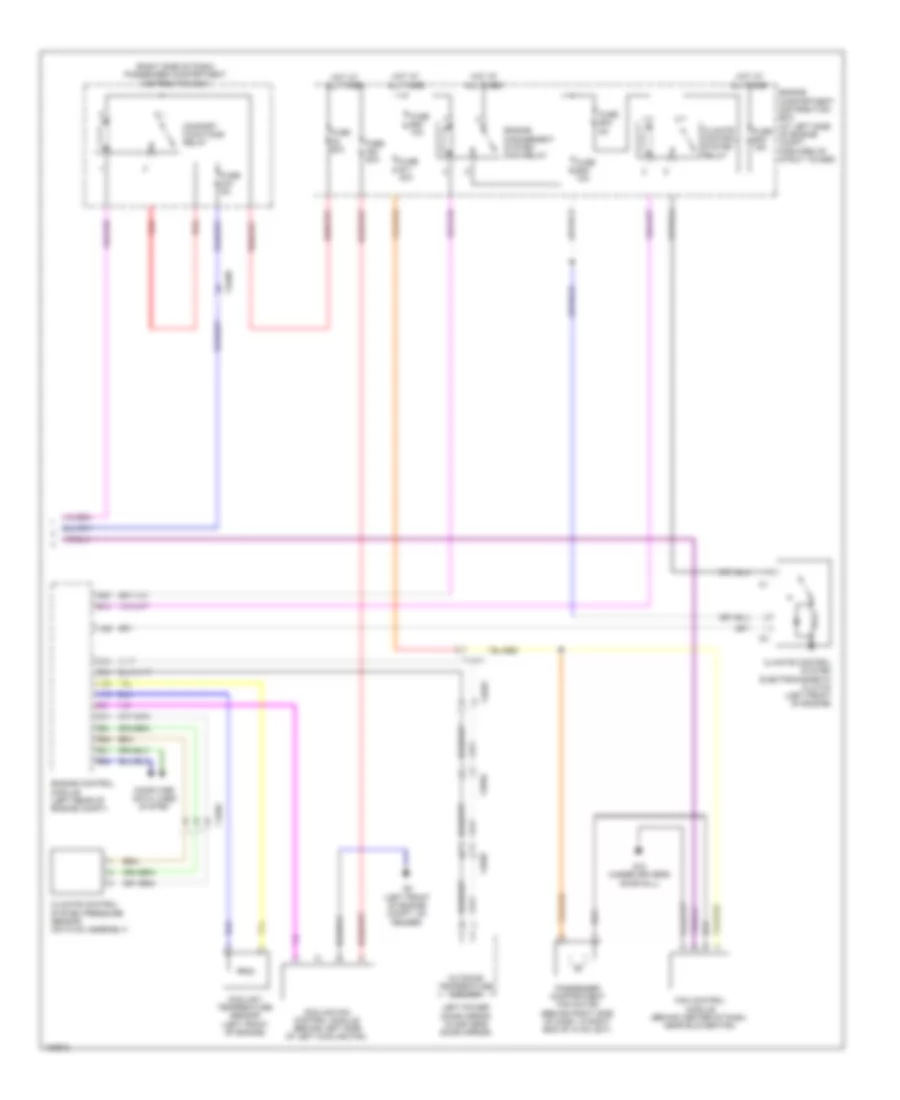
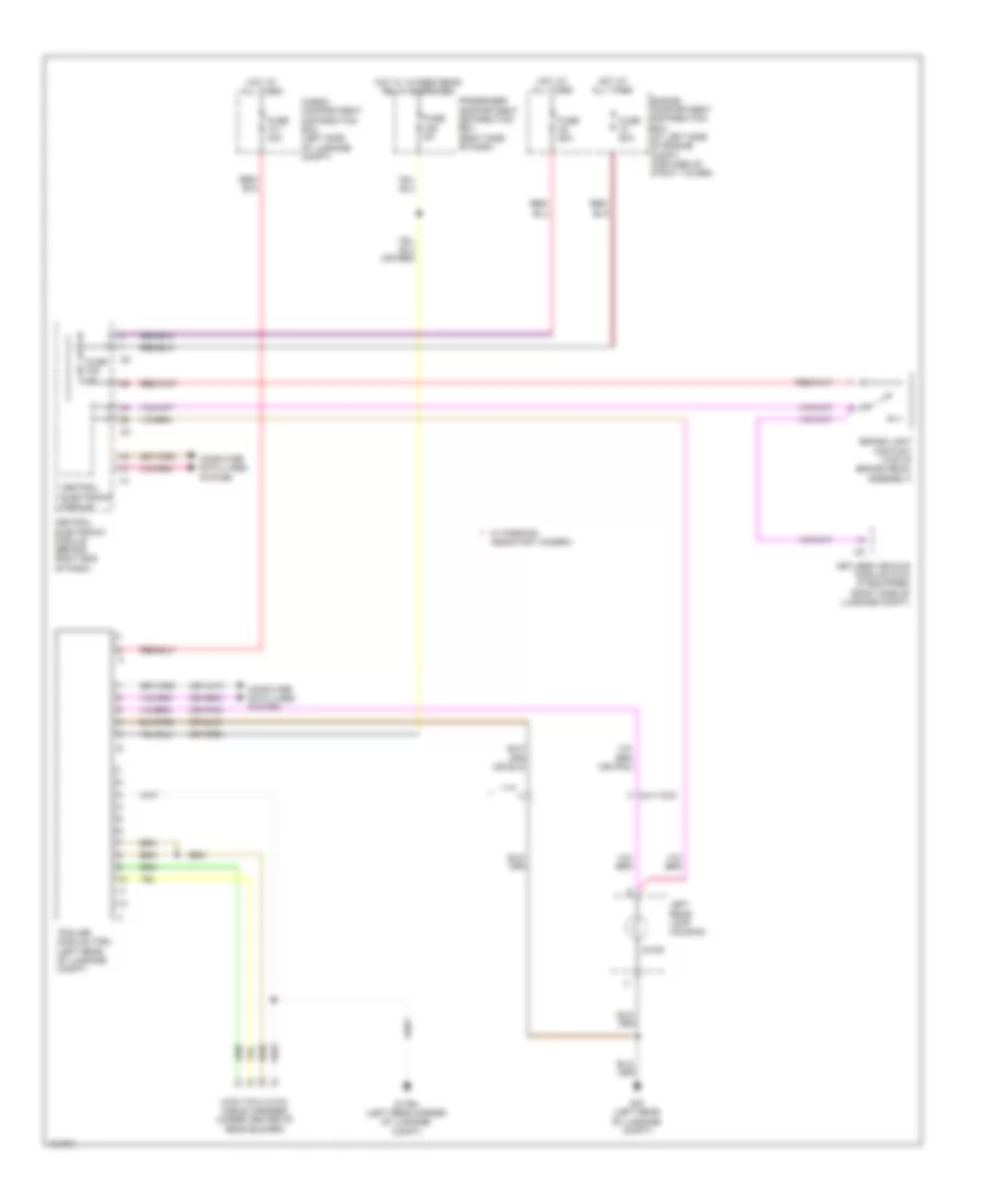
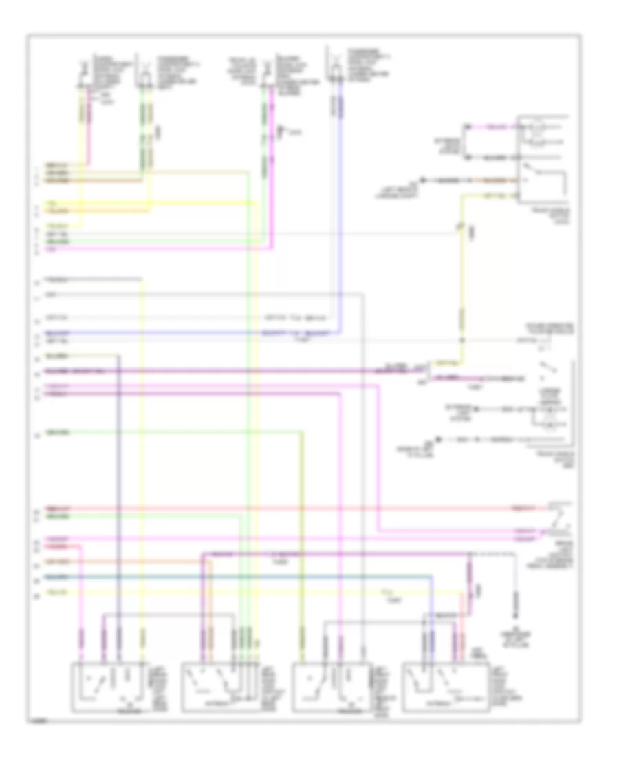
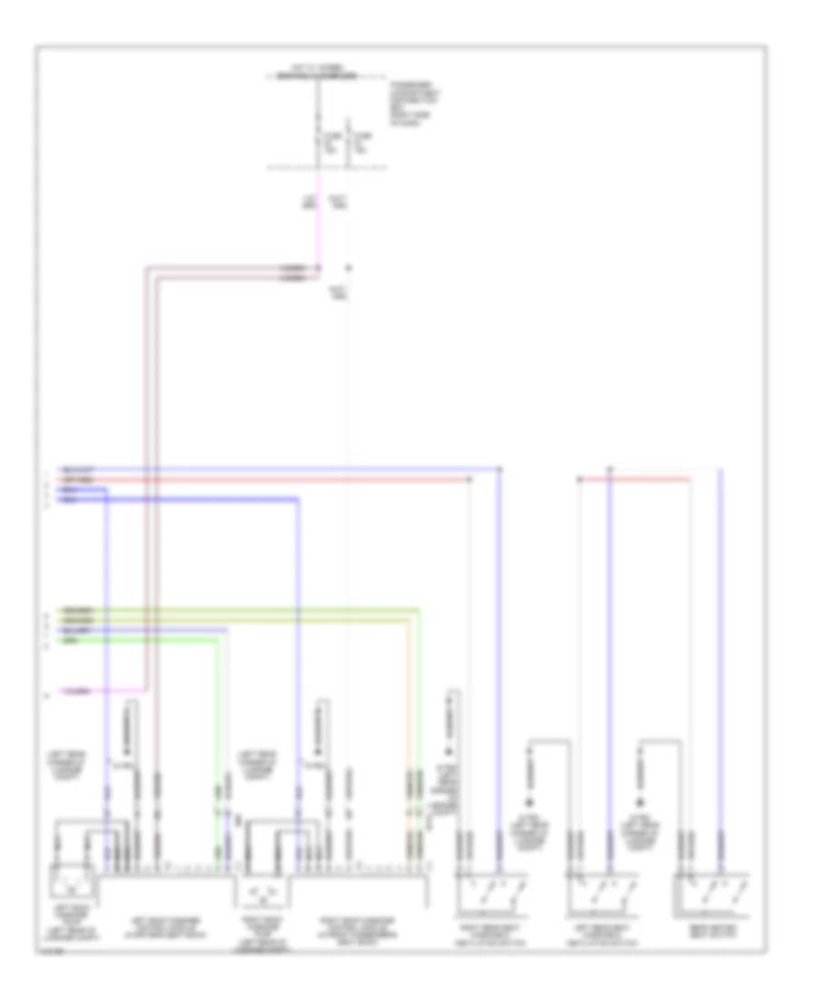
AIR CONDITIONING
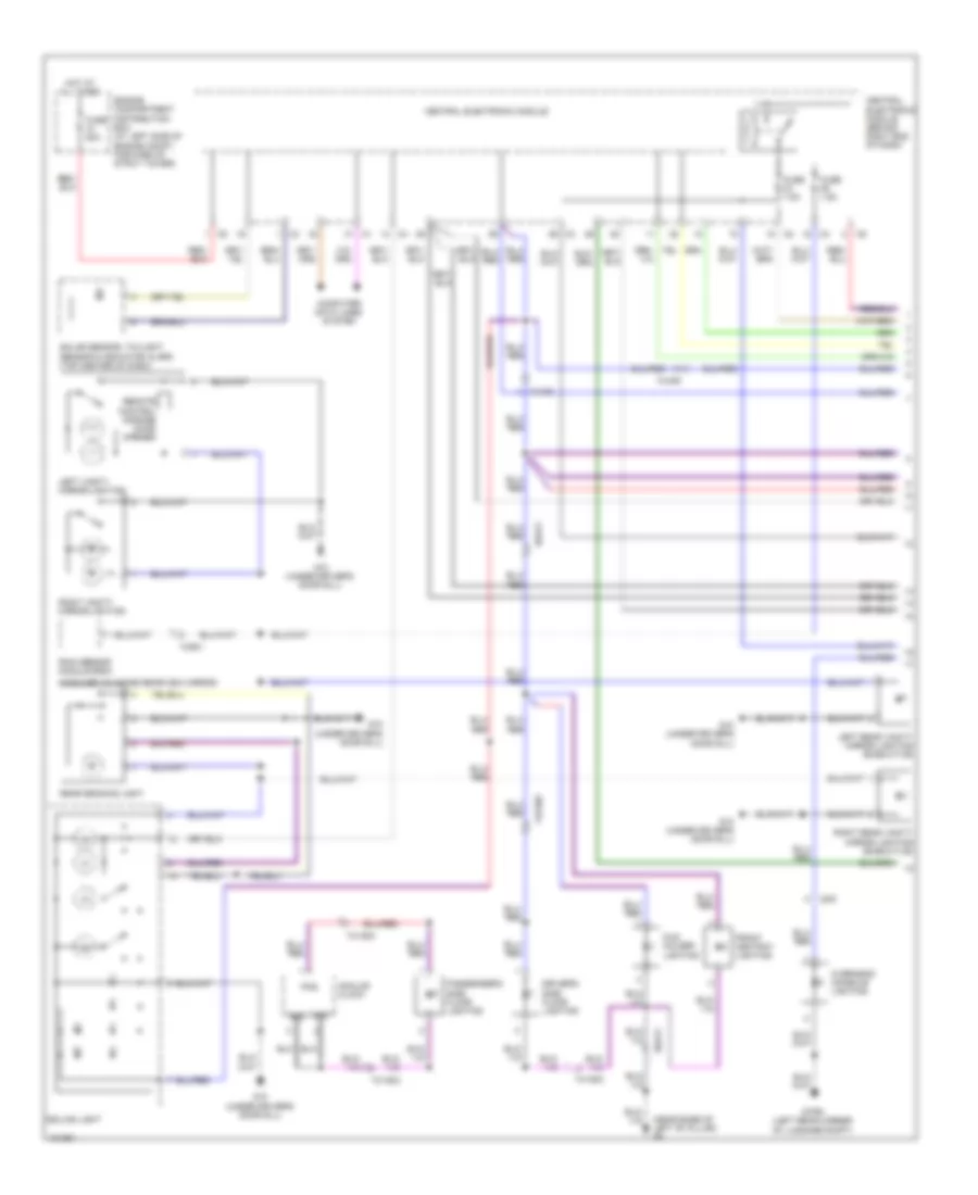
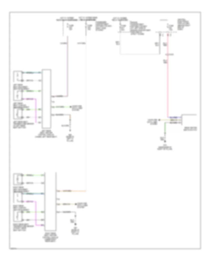
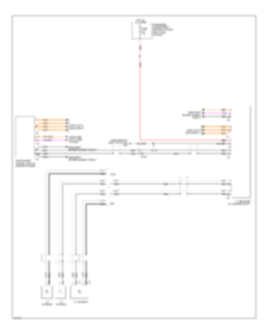
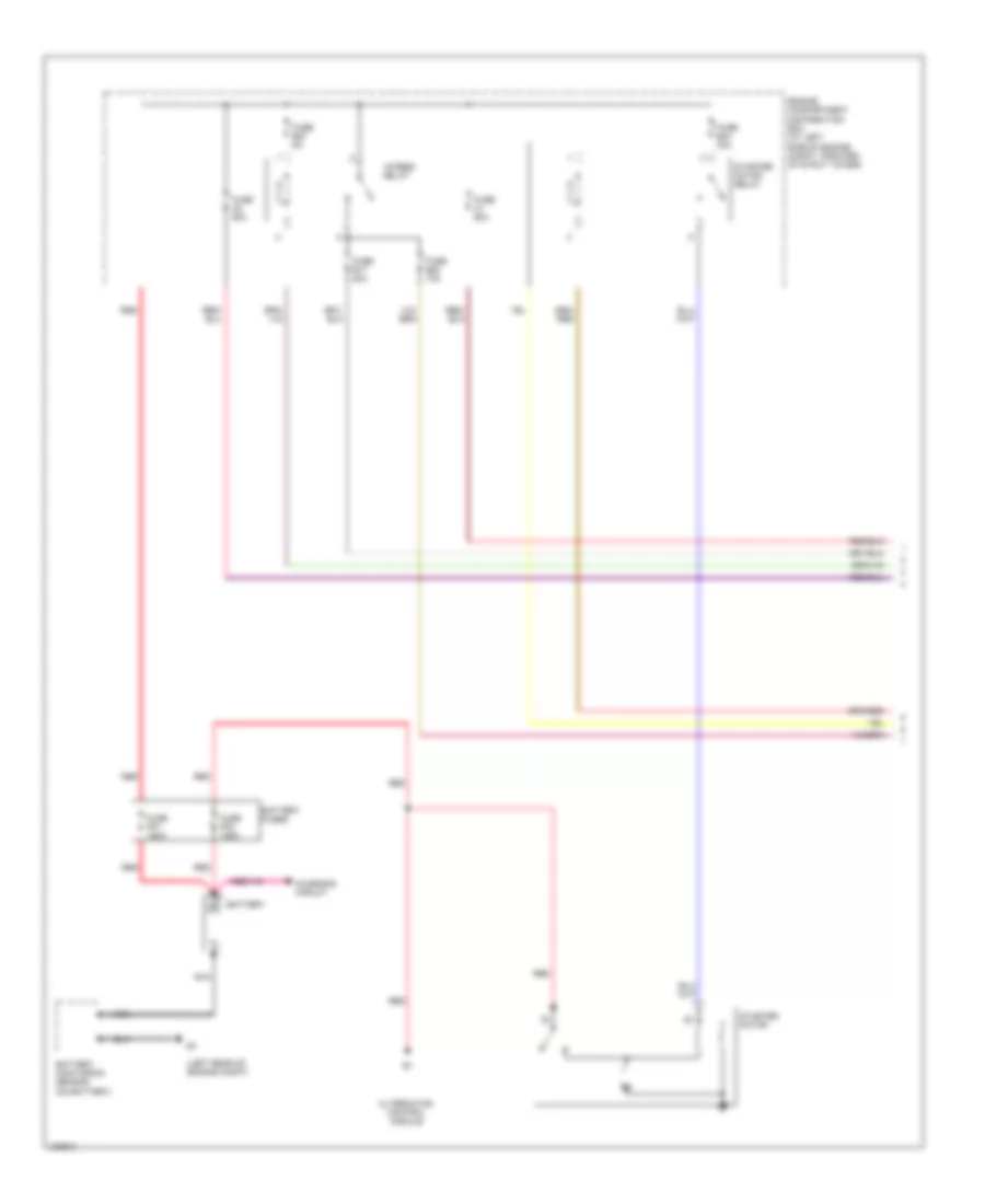
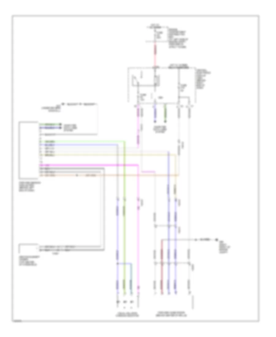
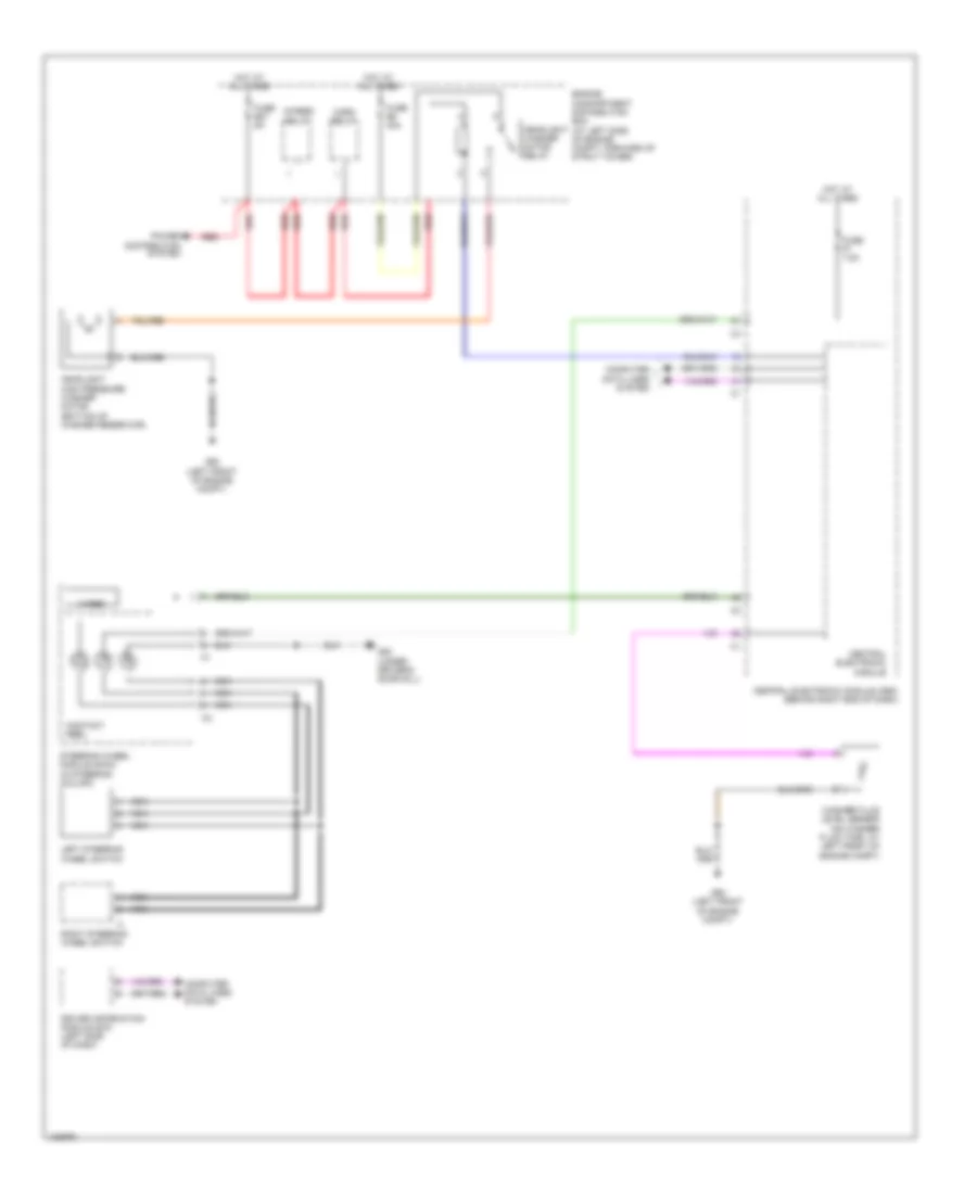
Automatic A/C Wiring Diagram (1 of 2) for Volvo S80 T6 2014
 https://portal-diagnostov.com/license.html
Automotive Electricians Portal FZCO
Automotive Electricians Portal FZCO
https://portal-diagnostov.com/license.html
https://portal-diagnostov.com/license.html
Automotive Electricians Portal FZCO
Automotive Electricians Portal FZCO
List of elements for Automatic A/C Wiring Diagram (1 of 2) for Volvo S80 T6 2014:
- (right front of engine compt, on fender) g1
- (under driver's door sill) g83
- 15- feed relay
- 74/401
- 74/417
- 74/504
- Air quality sensor (aqs)
- Auxiliary lights switch
- Central electronic module
- Central electronic module (cem) (behind right end of dash)
- Climate control module (center of dash)
- Climate control system
- Computer data lines system
- Defroster damper motor module (dmm)
- Engine compartment distribution box (at left side of engine compt, forward of strut tower)
- Evaporator temperature sensor
- Floor/ventilation damper motor module (dmm)
- Fuse a1 50a
- Fuse a2 50a
- Fuse a7 100a
- Fuse b17 20a
- Fuse b27 5a
- Fuse f14 5a
- Fuse f20 7.5a
- G10 (under driver's door sill)
- G83 (under driver's door sill)
- Heated rear window/rearview mirrors switch
- Hot at all times
- Left side temperature damper motor module (dmm)
- Pnk
- Ptc element (behind center of dash)
- Recirculation damper motor module (dmm)
- Red
- Right side temperature damper motor module (dmm)
- Solar sensor, twilight sensor & indicator alarm (top center of dash)
- Solid state
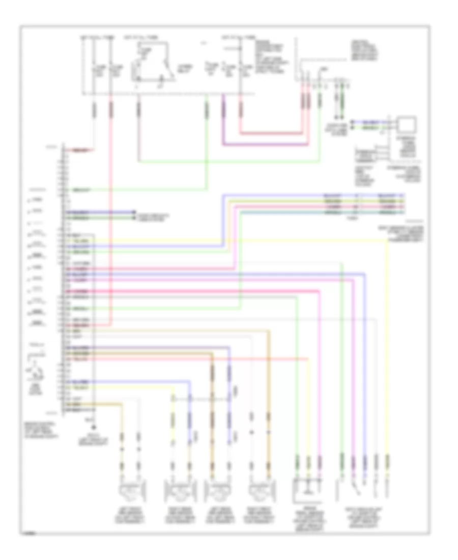
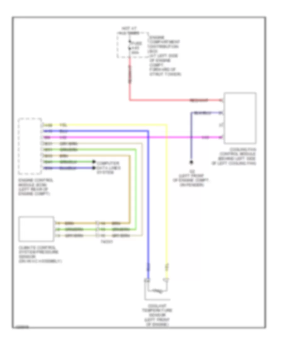
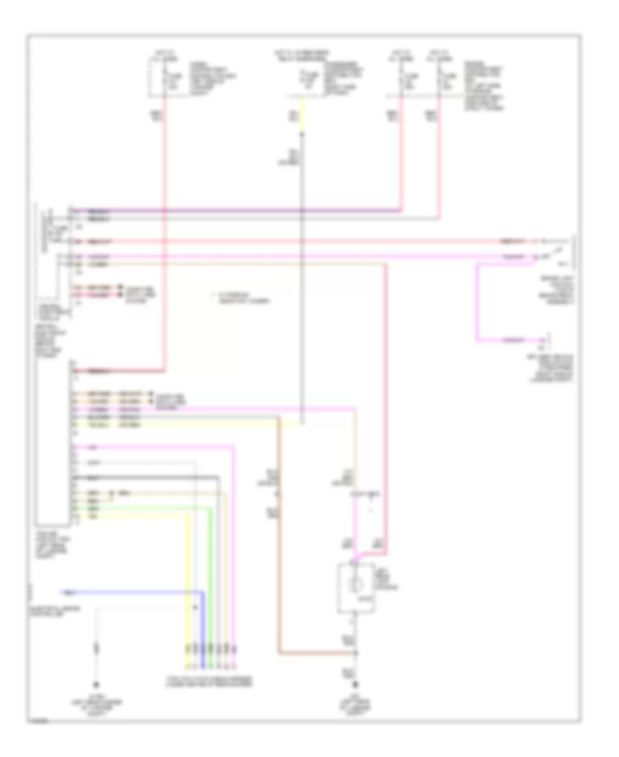
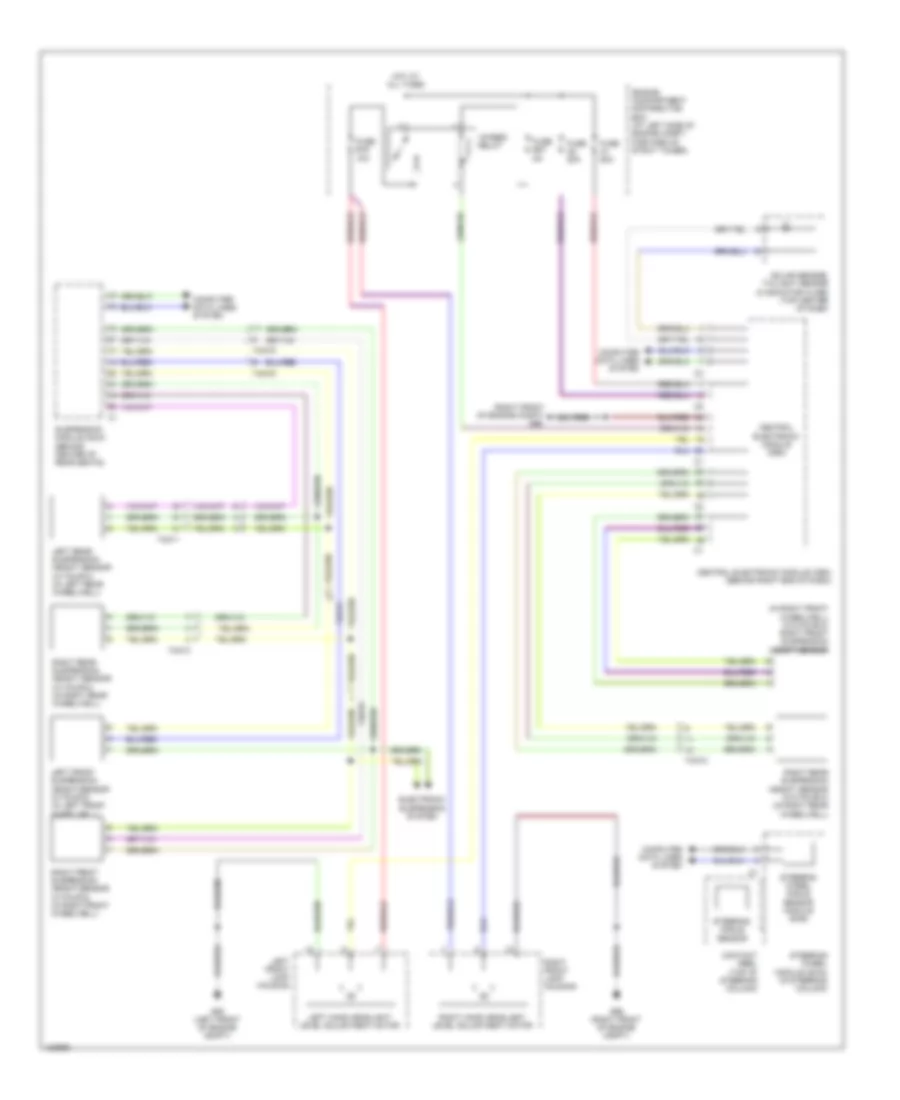
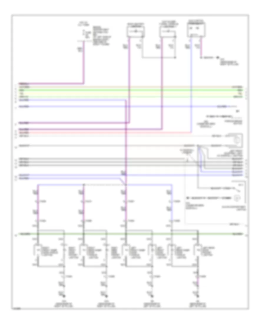
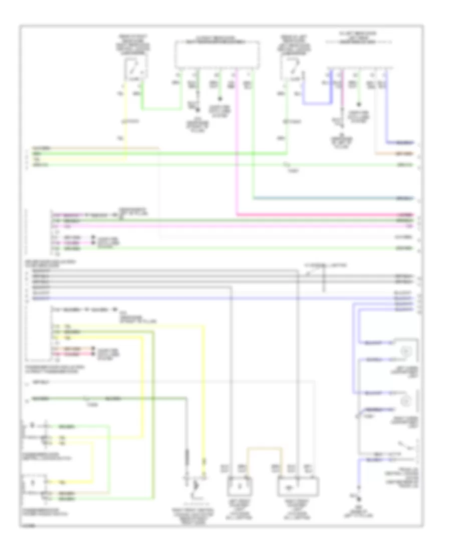
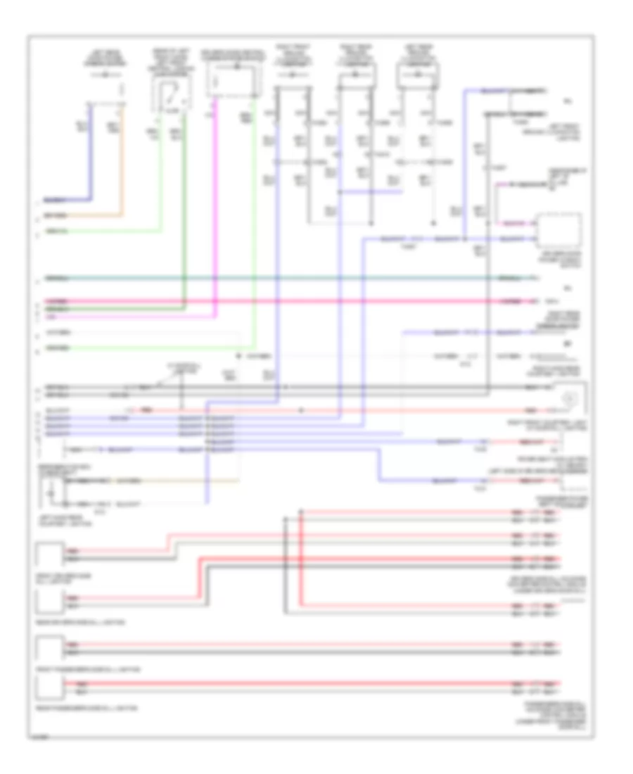
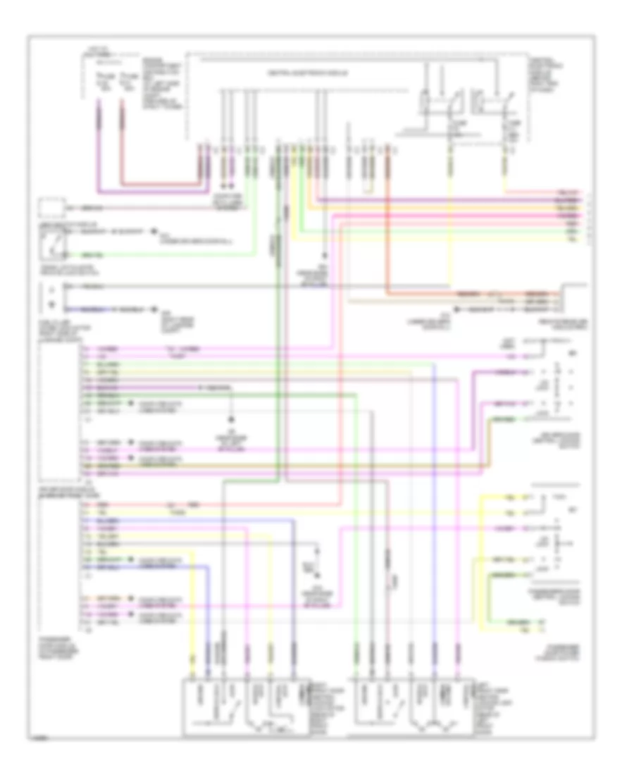
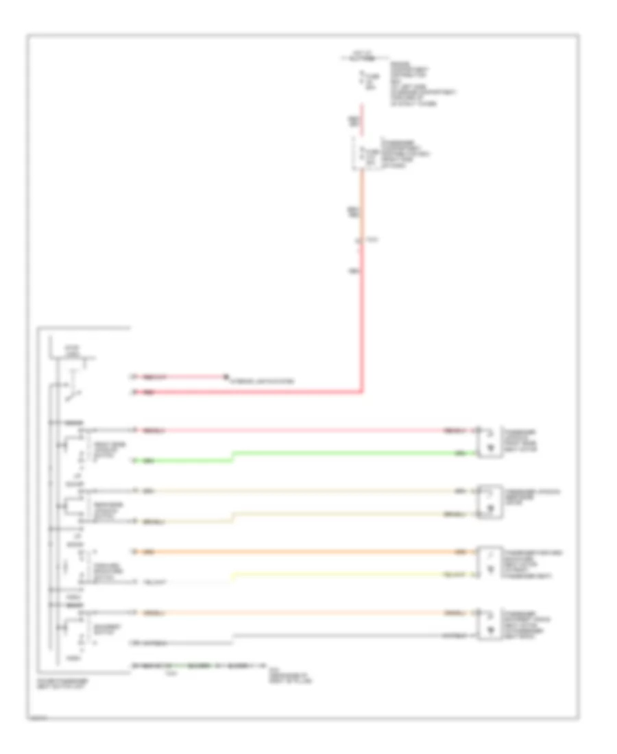
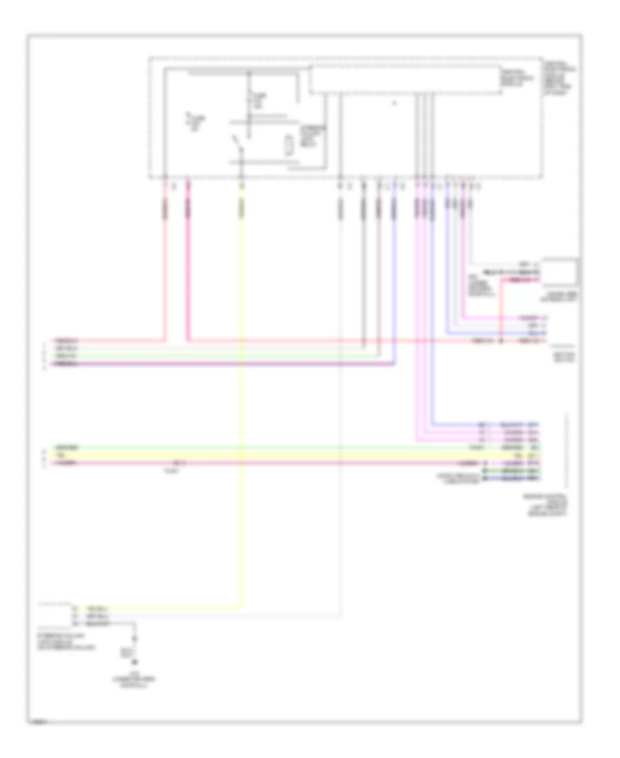
Automatic A/C Wiring Diagram (2 of 2) for Volvo S80 T6 2014
List of elements for Automatic A/C Wiring Diagram (2 of 2) for Volvo S80 T6 2014:
- (right side of dash) passenger compartment distribution box
- 74/301
- 74/409
- 74/411
- 74/504
- 74/507
- A13
- A68
- A85
- B10
- B27
- B31
- B34
- B35
- B41
- B51
- B53
- B54
- Climate control system electromagnetic clutch (left front of engine)
- Climate control system pressure sensor (on hvac assembly)
- Climate control system relay
- Comfort functions relay
- Computer data lines system
- Coolant temperature sensor (left front of engine)
- Cooling fan control module (behind left side of left cooling fan)
- Engine compartment distribution box (at left side of engine compt, forward of strut tower)
- Engine control module (left rear of engine compt)
- Engine management system main relay
- Fan control module (behind center of dash, near blower fan)
- Fuse a4 60a
- Fuse a43 80a
- Fuse b11 40a
- Fuse b30 10a
- Fuse b32 15a
- Fuse b33 5a
- Fuse b38 10a
- Fuse c21 5a
- G10 (under driver's door sill)
- G2 (left front of engine compt, on fender)
- Hot at all times
- Left power door mirror (in driver's door mirror)
- Outdoor temperature sensor
- Passenger compartment fan motor (behind right side of dash, in right end of hvac unit)
- Red
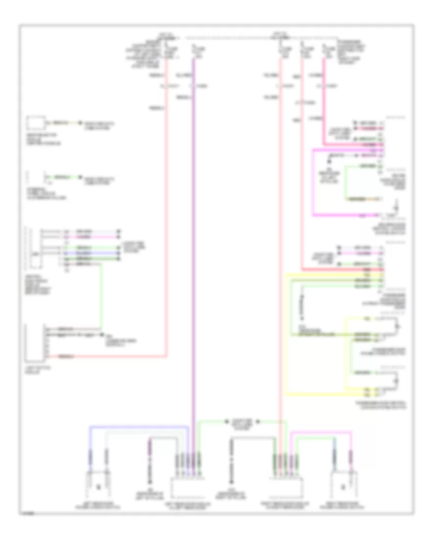
ANTI-LOCK BRAKES
Anti-lock Brakes Wiring Diagram for Volvo S80 T6 2014
List of elements for Anti-lock Brakes Wiring Diagram for Volvo S80 T6 2014:
- 15-feed relay
- 74/504
- 74/511
- 74/512
- Abs pump motor
- Body sensor cluster stability sensor (under front passenger seat)
- Brake control module (bcm) (at left rear of engine compt)
- Brake pedal sensor (w/ adaptive cruise control) (left rear of engine compt)
- Cem
- Central electronic module (cem) (behind right end of dash)
- Computer data lines system
- Contact reel (top of steering column)
- Dstc archive unit (w/ adaptive cruise control) (left rear of engine compt)
- Engine compartment distribution box (at left side of engine compt, forward of strut tower)
- Fuse a1 50a
- Fuse a2 50a
- Fuse b13 40a
- Fuse b14 20a
- Fuse b18 5a
- Fuse b27 5a
- Gxx14 (left front of engine compt)
- Hot at all times
- Left front abs sensor (on left front hub assembly)
- Left rear abs sensor (on left rear hub assembly)
- Right front abs sensor (on right front hub assembly)
- Right rear abs sensor (on right rear hub assembly)
- Steering angle sensor
- Steering wheel angle sensor module
- Steering wheel module (in steering column)
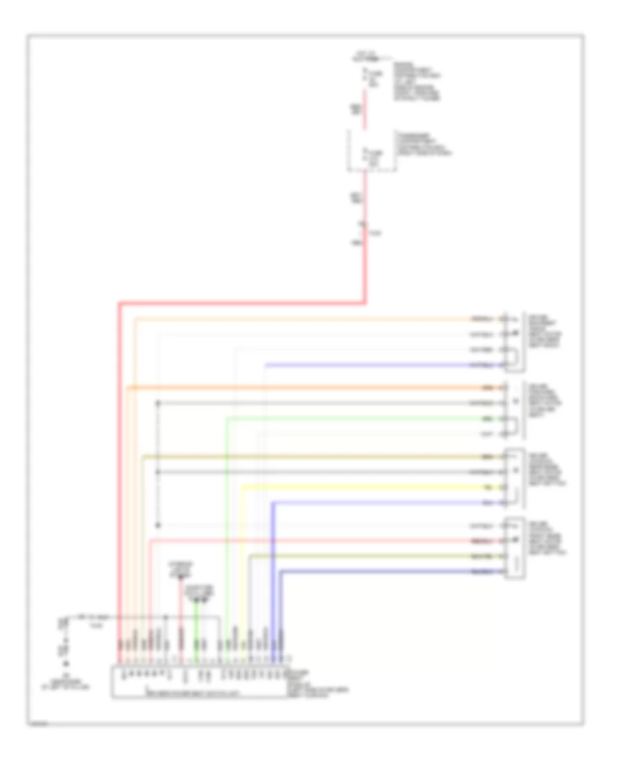
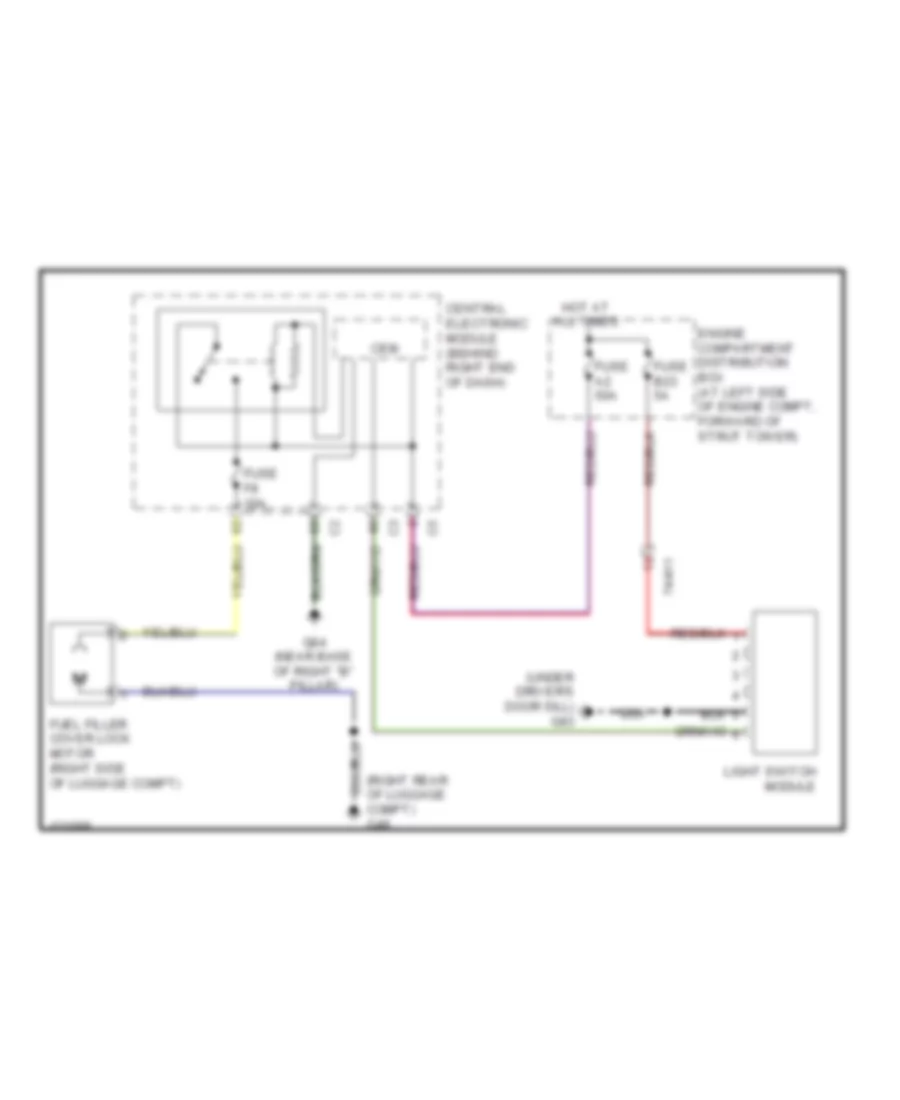
ANTI-THEFT
Anti-theft Wiring Diagram for Volvo S80 T6 2014
List of elements for Anti-theft Wiring Diagram for Volvo S80 T6 2014:
- (base of left "c" pillar) g65
- (center rear of trunk lid)
- (left rear door) left rear central locking lock motor
- 74/507
- 74/508
- 74/509
- 74/510
- 74/601
- 74/602
- Ajar
- Central electronic module
- Central electronic module (behind right end of dash)
- Climate control module (ccm) (center of dash)
- Computer data lines system
- Door locks system
- Driver's door module (in driver's front door)
- Engine compartment distribution box (at left side of engine compt, forward of strut tower)
- Fuse 50a
- Fuse f14 5a
- Fuse f16 5a
- G10 (under driver's door sill)
- G47 (left rear of luggage compt)
- G84 (near base of right "b" pillar)
- G93 (left front of engine compt)
- G96 (right front of engine compt)
- Hood alarm contact (center front of engine compt)
- Hot at all times
- Interior lights system
- Left front central locking lock motor (rear of left front door)
- Left rear door module (in left rear door)
- Passenger's door module (in passenger's front door)
- Power operated tailgate module (xc70)
- Red
- Right front central locking lock motor (rear of right front door)
- Right rear central locking lock motor (right rear door)
- Right rear door module (in right rear door)
- S80
- Siren control module (scm) (right rear of engine compt)
- Solar sensor, twilight sensor & indicator alarm (top center of dash)
- Trunk lid central locking motor (s80) (center rear of trunk lid)
- Trunk lid central locking motor (xc70)
- Trunk, tailgate, fuel doors system
- Ultrasonic sensor (ims) (center of roof)
- Xc70
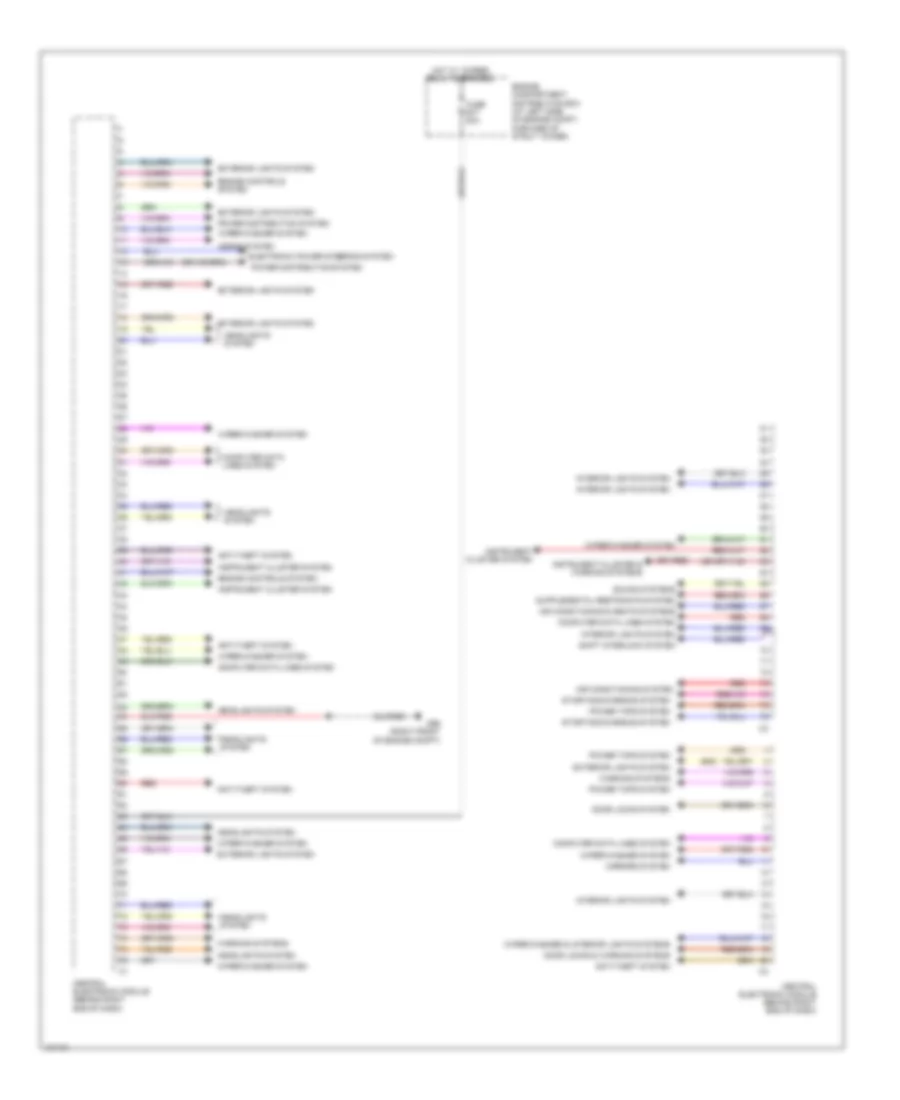
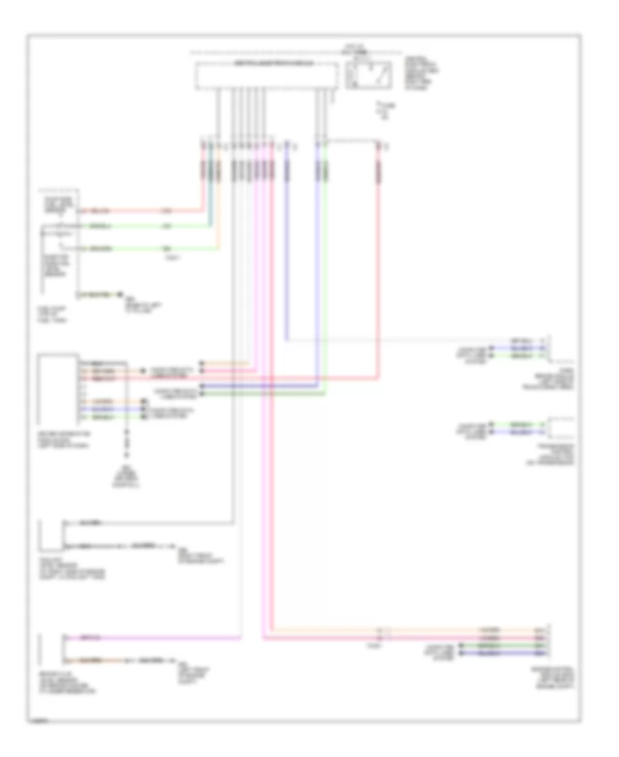
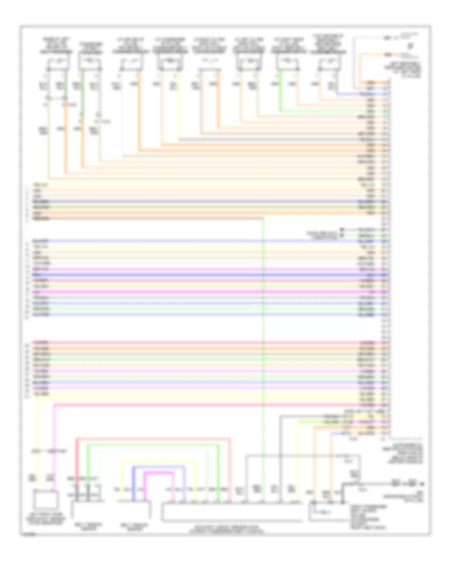
BODY CONTROL MODULES
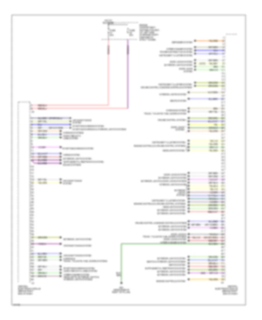
Body Control Modules Wiring Diagram (1 of 2) for Volvo S80 T6 2014
List of elements for Body Control Modules Wiring Diagram (1 of 2) for Volvo S80 T6 2014:
- (s80)
- Air conditioning & seats systems
- Air conditioning system
- Anti-theft system
- Central electronic module (behind right end of dash)
- Computer data lines system
- Door locks & warning systems
- Door locks system
- Electronic power steering system
- Engine compartment distribution box (at left side of engine compt, forward of strut tower)
- Engine controls system
- Exterior lights system
- Fuse b17 20a
- G96 (right front of engine compt)
- Headlights system
- Horns system
- Hot w/ 15-feed relay energized
- Instrument cluster & warning systems
- Instrument cluster system
- Interior lights system
- Mirrors system
- Power distribution system
- Power tops system
- Red
- Shift interlock system
- Sound systems
- Starting/charging system
- Warning systems
- Wiper/washer & interior lights systems
- Wiper/washer system
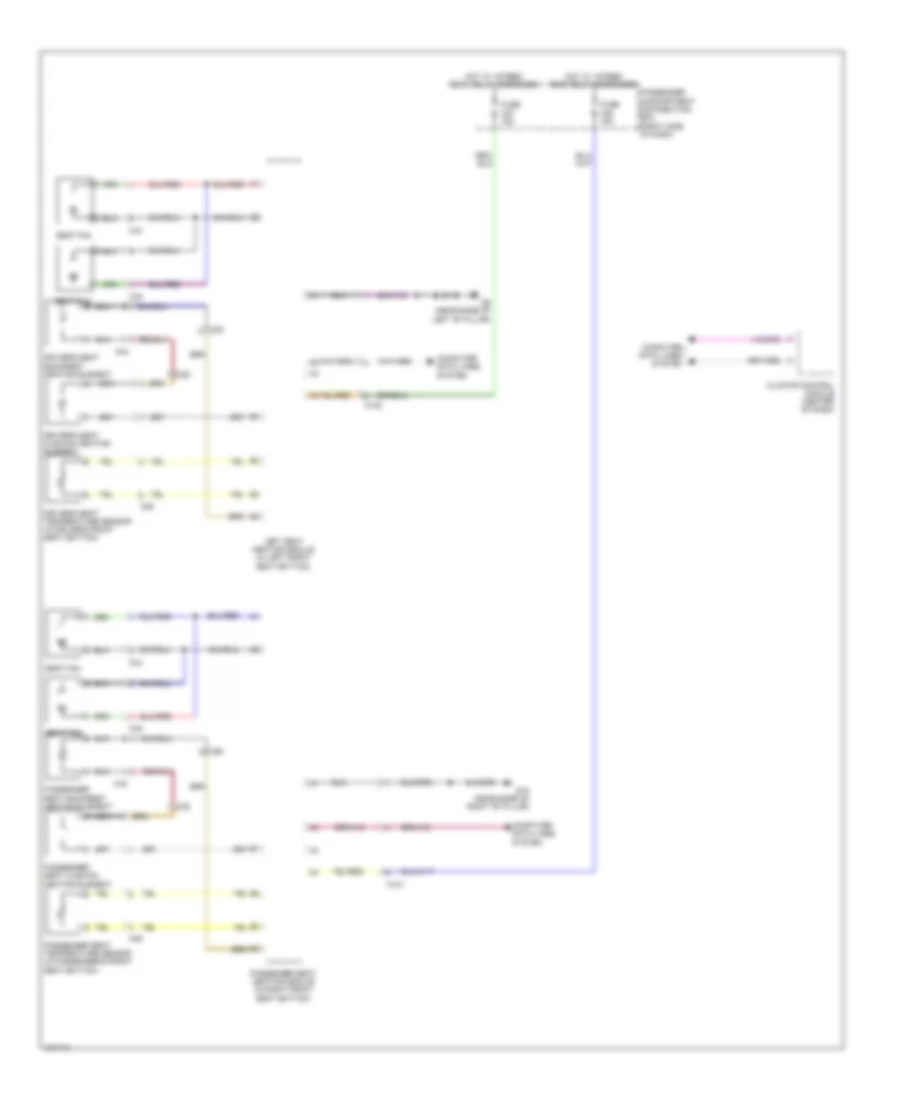
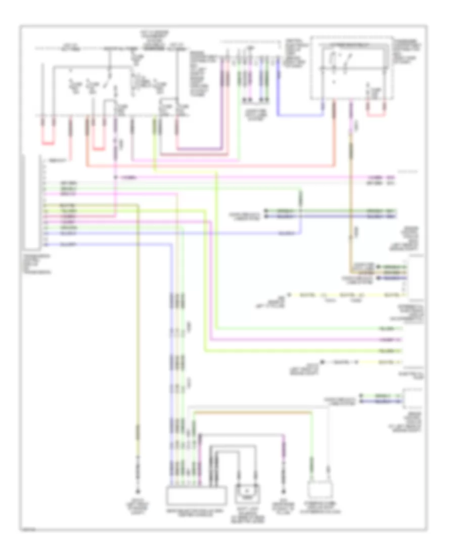
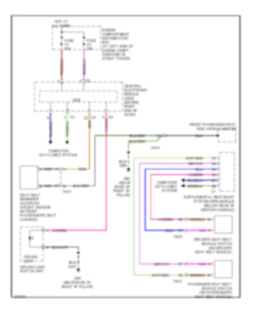
Body Control Modules Wiring Diagram (2 of 2) for Volvo S80 T6 2014
List of elements for Body Control Modules Wiring Diagram (2 of 2) for Volvo S80 T6 2014:
- (s80)
- (xc70)
- Air conditioning system
- Central electronic module (behind right end of dash)
- Computer data lines system
- Cruise control & engine controls systems
- Cruise control system
- Defogger system
- Door locks & trunk, tailgate, fuel doors systems door locks system
- Door locks system
- Engine compartment distribution box (at left side of engine compt, forward of strut tower)
- Engine controls & cruise control systems
- Engine controls system
- Exterior lights & door locks systems
- Exterior lights system
- Fuse a1 50a
- Fuse a2 50a
- G84 (near base of right "b" pillar)
- Headlights system
- Horns system
- Hot at all times
- Instrument cluster system
- Interior lights system
- Power distribution system
- Seats & interior lights systems
- Seats system
- Sound systems
- Starting/charging & interior lights systems
- Starting/charging system
- Trunk, tailgate, fuel doors system
- Warning & trunk, tailgate, fuel doors systems
- Warning systems
- Wiper/washer system
- Wiper/washer system headlights, exterior lights & interior lights systems
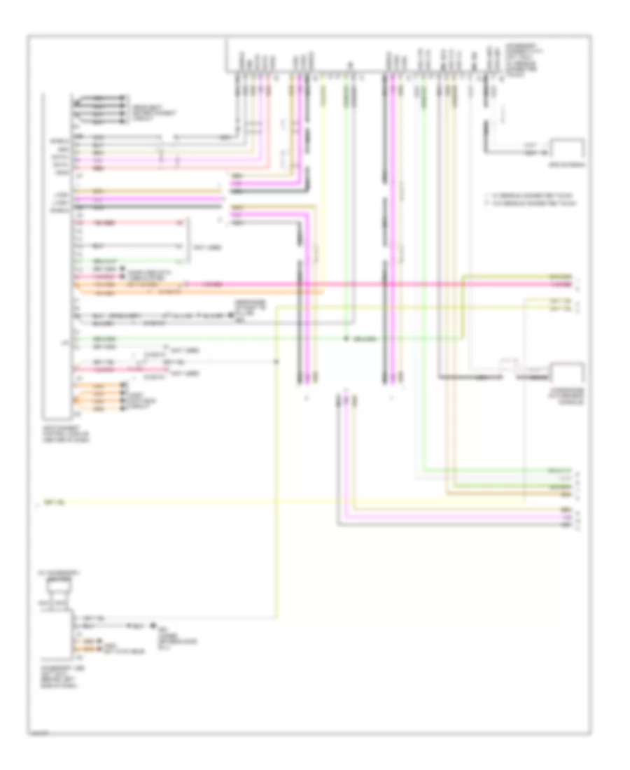
COMPUTER DATA LINES
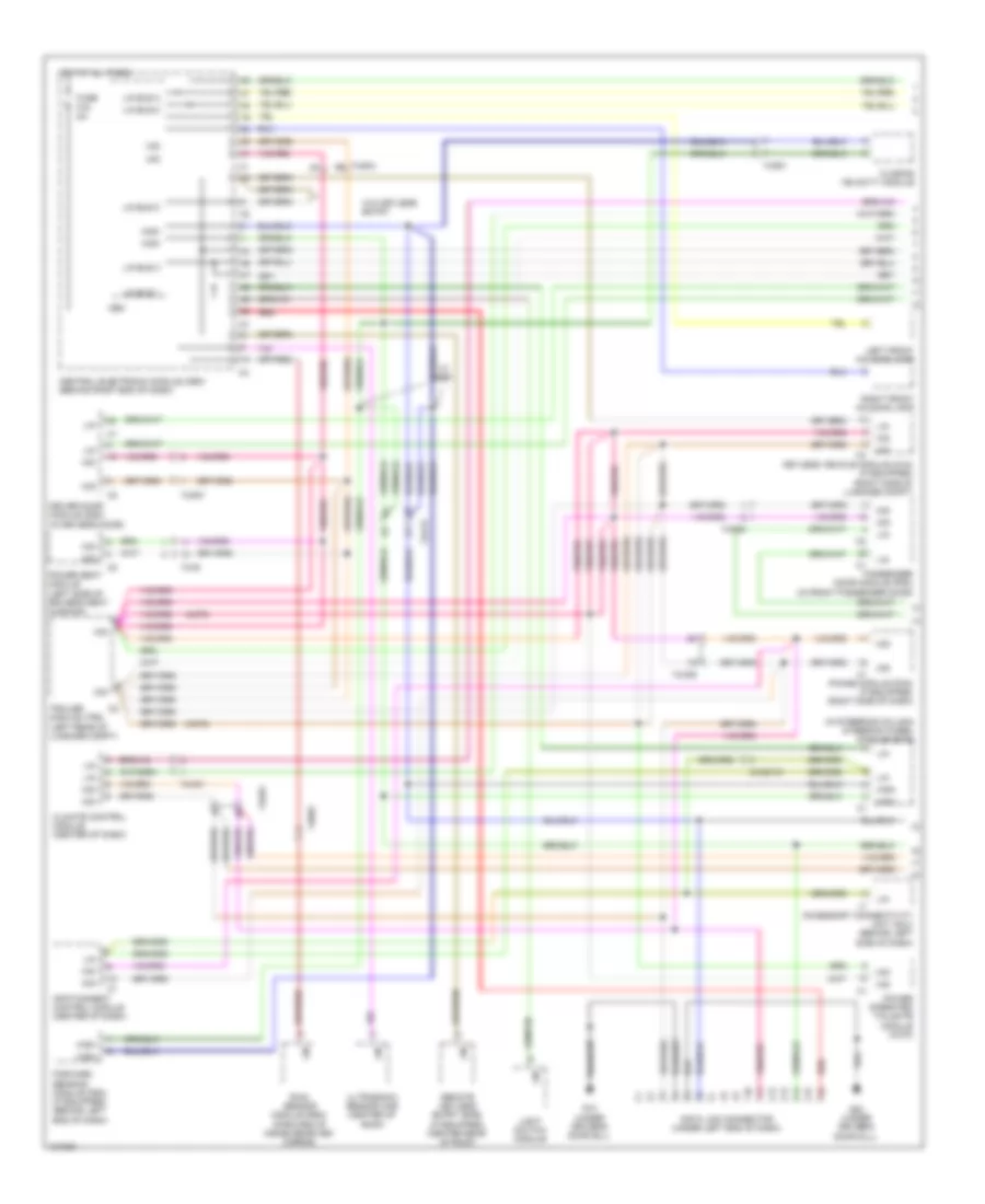
Computer Data Lines Wiring Diagram (1 of 3) for Volvo S80 T6 2014
List of elements for Computer Data Lines Wiring Diagram (1 of 3) for Volvo S80 T6 2014:
- (in steering column) steering wheel module (swm)
- (xc70)
- 3x/281c1
- 74/30
- 74/401
- 74/409
- 74/412
- 74/504
- 74/507
- 74/508
- 74/901
- Accessory connectivity unit (acu) (behind left side of dash)
- Cem
- Central electronic module (cem) (behind right end of dash)
- Climate control module (center of dash)
- Closing velocity module
- Data link connector (under left end of dash)
- Driver door module (ddm) (in driver's door)
- Forward sensing module (fsm) (if equipped) (behind left end of dash)
- Fuse f16 5a
- G10 (under driver's door sill)
- G83 (under driver's door sill)
- High
- Hot at all times
- Infotainment control module (center of dash)
- Keyless vehicle module (kvm) (if equipped) (right side of luggage compt)
- Left front housing lamp
- Light switch module
- Lin
- Lin bus 0
- Lin bus 1
- Lin bus 2
- Lin bus 3
- Lin bus 8
- Mid
- Passenger door module (pdm) (in front passenger door)
- Phone module (phm) (if equipped) (right side of dash)
- Power operated tailgate module (xc70)
- Power seat module (left side of driver's seat cushion)
- Rain sensor module (rsm) (forward of inside rearview mirror)
- Red
- Remote keyless entry (rke) (if equipped) (center rear of roof)
- Right front housing lamp
- Trailer module (trm) (left rear of luggage compt)
- Ultrasonic sensor (ims) (center of roof)
- W/ acc
- W/o keyless entry
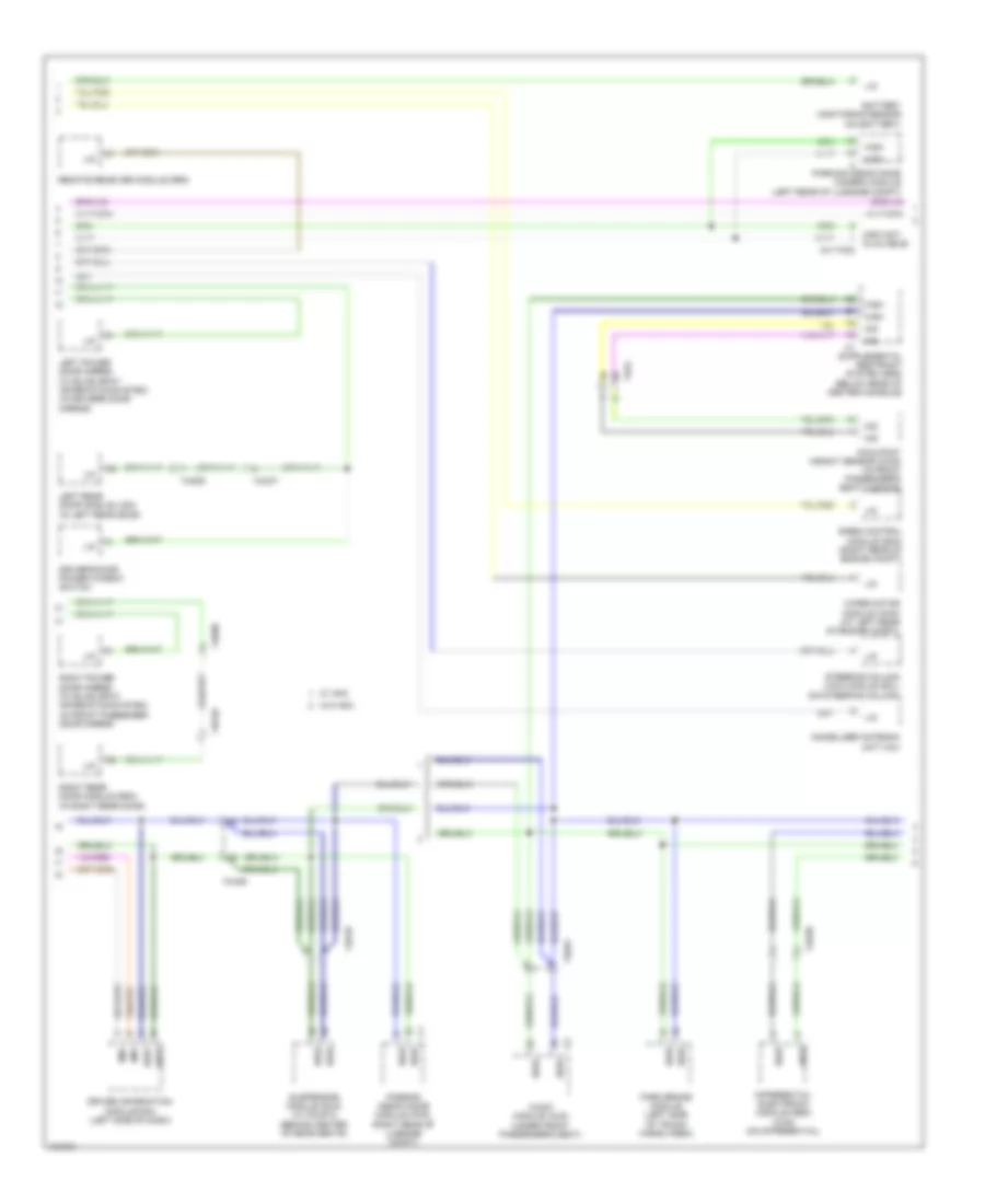
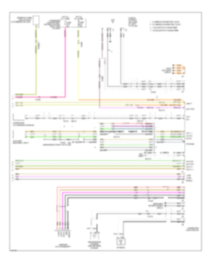
Computer Data Lines Wiring Diagram (2 of 3) for Volvo S80 T6 2014
List of elements for Computer Data Lines Wiring Diagram (2 of 3) for Volvo S80 T6 2014:
- (info not available)
- 4x/110c2
- 74/31
- 74/409
- 74/507
- 74/508
- 74/509
- 74/510
- 74/518
- 74/520
- 74/561
- Audio module (aud) (under front passenger's seat)
- Battery monitoring sensor (on battery)
- Differential electronic module (dem) (4wd) (on differential)
- Driver information module (dim) (left side of dash)
- Driver's door power window switch
- High
- Immobilizer antenna unit (iau)
- Left power door mirror (w/ blind spot information system) (in driver's door mirror)
- Left rear door module (ldm) (in left rear door)
- Lin
- Mid
- Occupant weight sensor (ows) (in front passenger's seat cushion)
- Park brake module (left side of trunk/ cargo area)
- Parking assistance camera module (left rear of luggage compt)
- Parking assistance module (pam) (right rear of luggage compt)
- Remote receiver module (rrx)
- Right power door mirror (w/ blind spot information system) (in front passenger door mirror)
- Right rear door module (rdm) (in right rear door)
- Siren control module (scm) (right rear of engine compt)
- Steering column lock module (scl) (on steering column)
- Suspension module (sum) (w/ four c) (behind center of rear seats)
- W/ anc
- W/o anc
- Wiper motor module (wmm) (at left rear of engine compt)
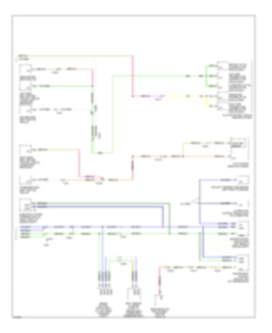
Computer Data Lines Wiring Diagram (3 of 3) for Volvo S80 T6 2014
List of elements for Computer Data Lines Wiring Diagram (3 of 3) for Volvo S80 T6 2014:
- 3.2l pzev
- 4wd
- 74/30
- 74/301
- 74/31
- 74/403
- 74/409
- 74/411
- 74/412
- 74/417
- 74/501
- 74/504
- 74/511
- 74/901
- A92
- Alternator control module (acm) (in alternator)
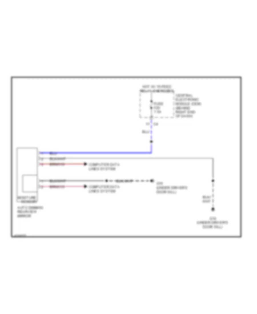
- Auto dimming rearview mirror
- B41
- B54
- Body sensor cluster stability sensor (bsc) (under front passenger seat)
- Brake control module (bcm) (at left rear of engine compt)
- Climate control module (center of dash)
- Coolant temperature sensor (left front of engine)
- Defroster damper motor module (dmm)
- Driver's side seat heating module
- Electrical power steering module (right front of engine compt)
- Engine control module (ecm) (left rear of engine compt)
- Floor/ventilation damper motor module (dmm)
- Gear selector module (gsm) (center console)
- High
- Left rear seat heater control module (under left rear seat)
- Left side temperature damper motor module (dmm)
- Lin
- Moisture sensor
- Passenger side seat heating module
- Rear heated seats switch
- Recirculation damper motor module (dmm)
- Right rear seat heater control module (under right rear seat)
- Right side temperature damper motor module (dmm)
- Transmission control module (tcm) (on transmission)
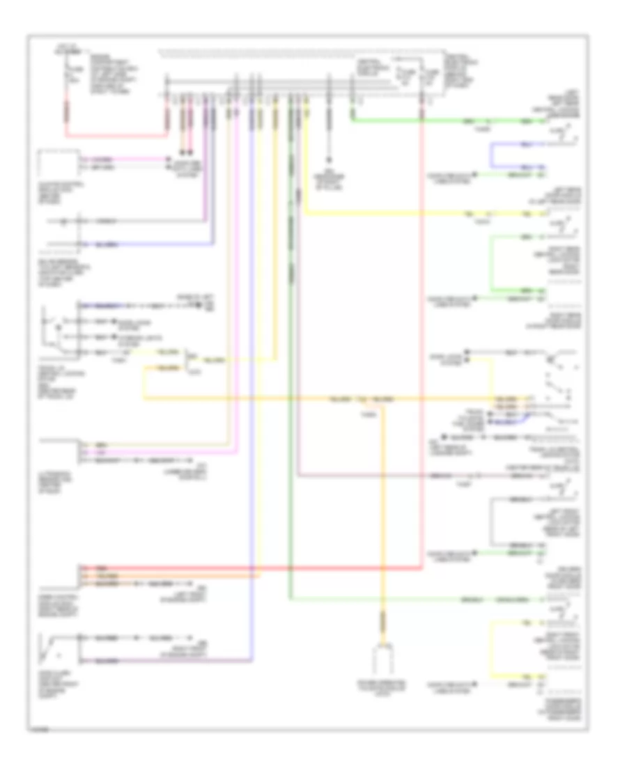
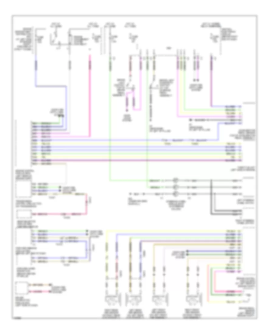
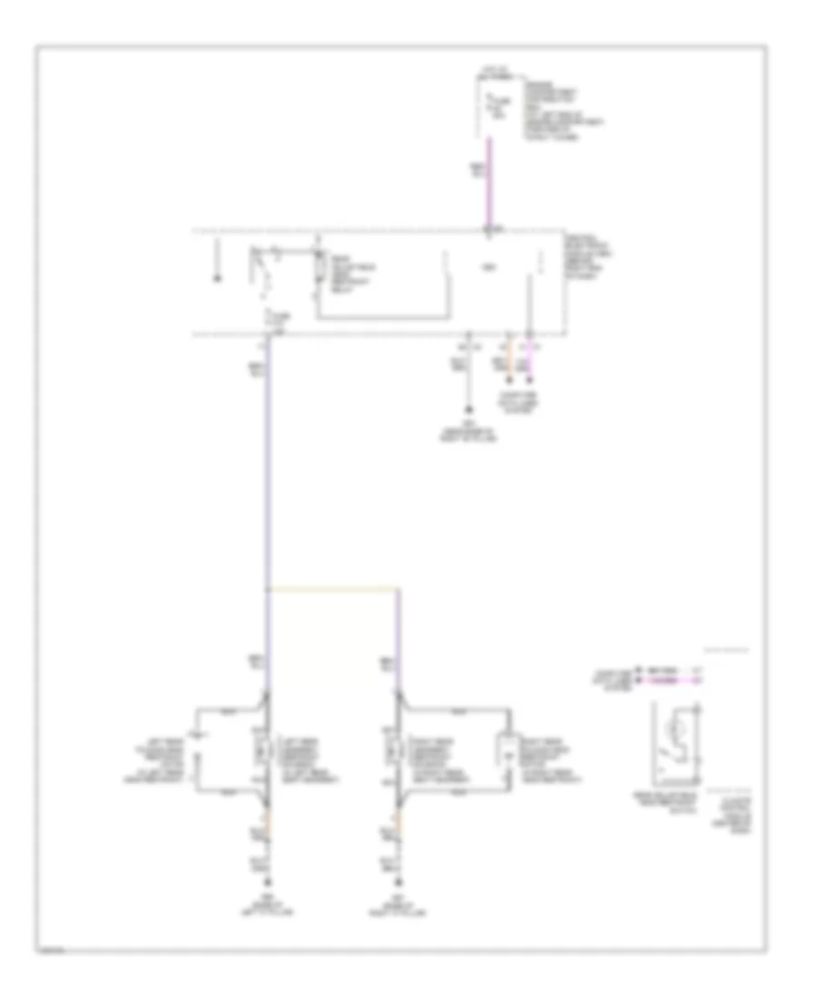
COOLING FAN
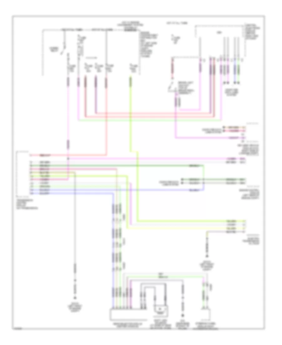
Cooling Fan Wiring Diagram for Volvo S80 T6 2014
List of elements for Cooling Fan Wiring Diagram for Volvo S80 T6 2014:
- 74/301
- A13
- A68
- B31
- B41
- B51
- B53
- B54
- Climate control system pressure sensor (on hvac assembly)
- Computer data lines system
- Coolant temperature sensor (left front of engine)
- Cooling fan control module (behind left side of left cooling fan)
- Engine compartment distribution box (at left side of engine compt, forward of strut tower)
- Engine control module (ecm) (left rear of engine compt)
- Fuse a43 80a
- G2 (left front of engine compt, on fender)
- Hot at all times
CRUISE CONTROL
Cruise Control Wiring Diagram for Volvo S80 T6 2014
List of elements for Cruise Control Wiring Diagram for Volvo S80 T6 2014:
- 74/301
- 74/321
- 74/403
- 74/411
- 74/412
- 74/504
- 74/511
- 74/512
- A14
- A17
- A48
- A65
- A67
- A73
- A74
- A75
- Accelerator pedal sensor (top of accelerator pedal assembly)
- B13
- B16
- B26
- B27
- B41
- B54
- Brake control module (bcm) (at left rear of engine compt)
- Brake light contact (top of brake pedal assembly)
- Brake light diagnostic contact (at top of brake pedal assembly)
- Brake pedal sensor (left rear of engine compt)
- Cem
- Central electronic module (behind right end of dash)
- Computer data lines system
- Door locks system
- Driver information module (dim) (left side of dash)
- Engine compartment distribution box (at left side of engine compt, forward of strut tower)
- Engine control module (ecm) (left rear of engine compt)
- Engine management system main relay
- Forward aimed radar (flr) (behind center of grille)
- Forward sensing module (fsm) (behind left end of dash)
- Fuse b30 10a
- Fuse b36 10a
- Fuse f20 7.5a
- Fuse f22 5a
- Fuse f7 7.5a
- G7 (near base of left "b" pillar)
- G83 (under driver's door sill)
- Gear selector module (gsm) (center console)
- Hot at all times
- Hot w/ 15-feed relay energized
- Left front abs sensor (on left front hub assembly)
- Left rear abs sensor (on left rear hub assembly)
- Left steering wheel switch
- Nca
- Right front abs sensor (on right front hub assembly)
- Right rear abs sensor (on right rear hub assembly)
- Right steering wheel switch
- Steering wheel module (swm) (in steering column)
- Throttle unit (left side of engine)
- Transmission control module (tcm) (on transmission)
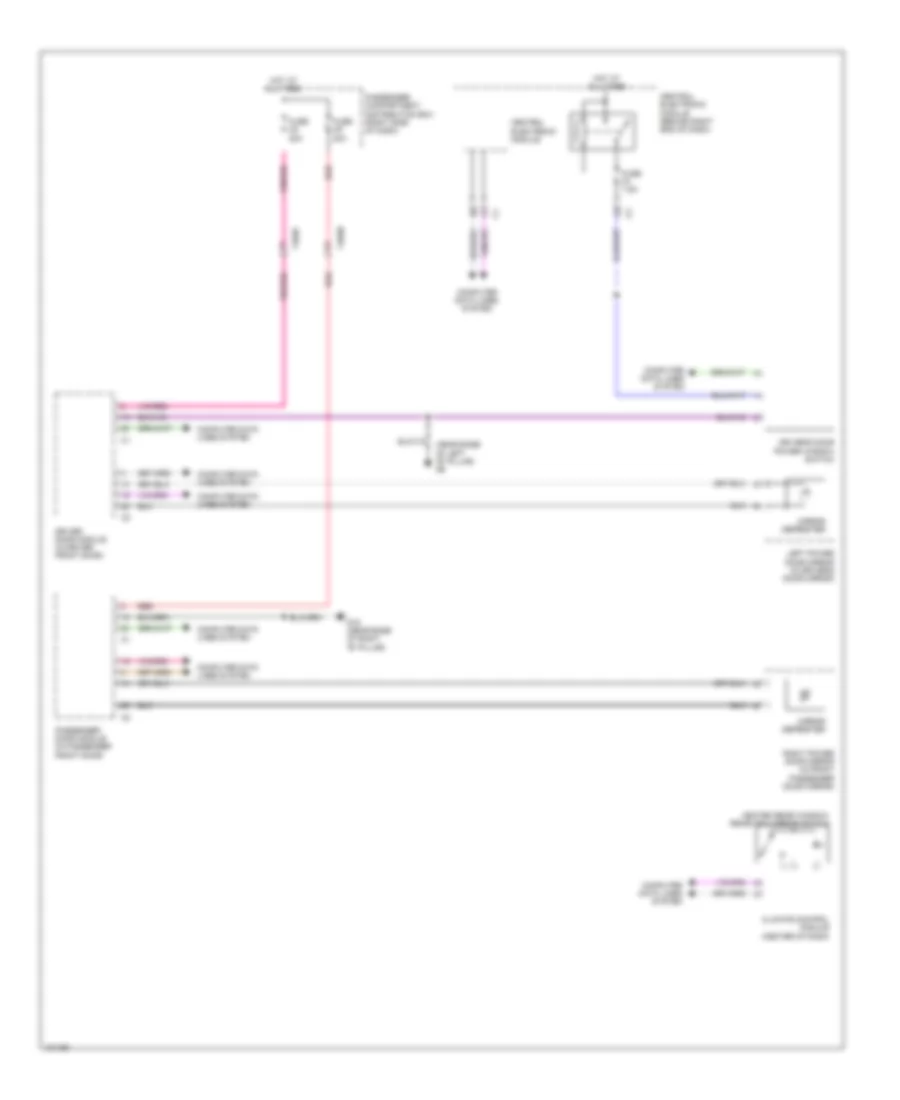
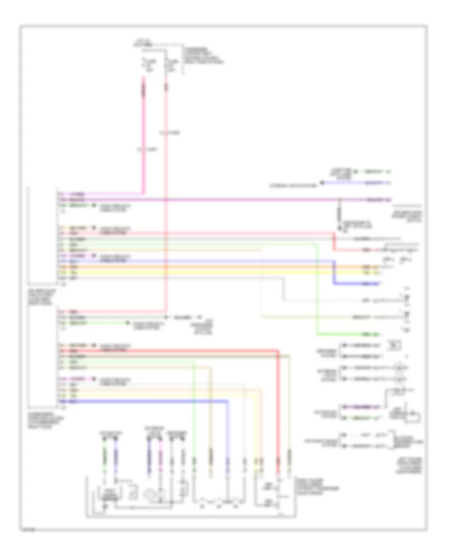
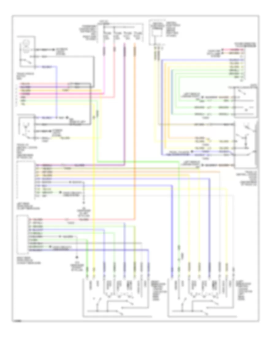
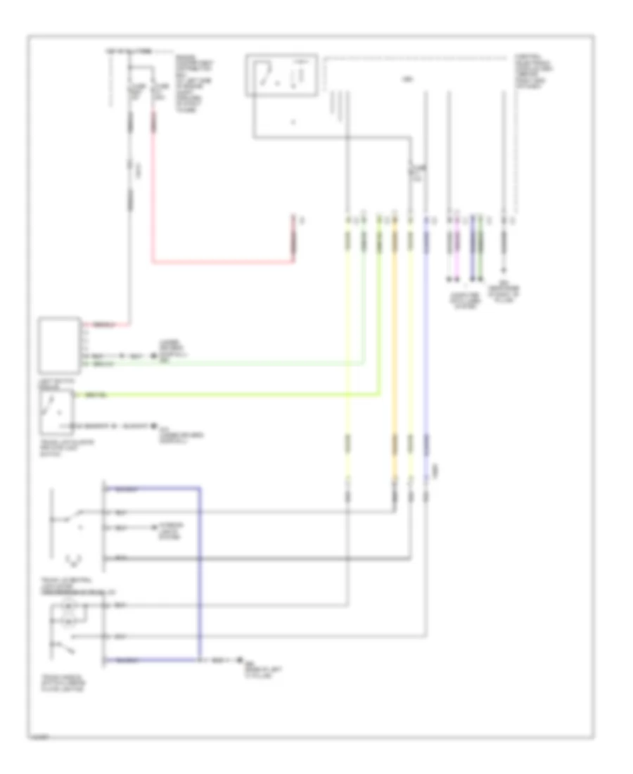
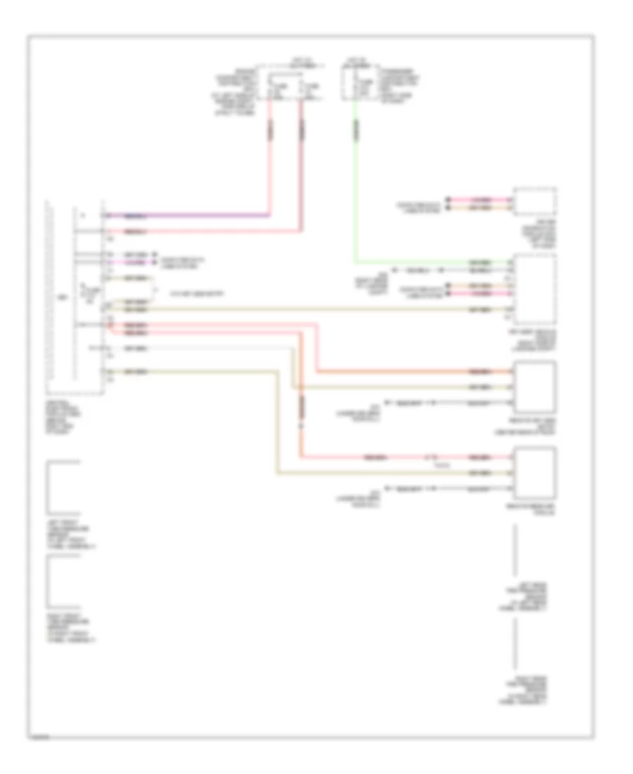
DEFOGGERS
Heated Mirrors Wiring Diagram for Volvo S80 T6 2014
List of elements for Heated Mirrors Wiring Diagram for Volvo S80 T6 2014:
- (near base of left "b" pillar) g6
- 74/507
- 74/508
- Central electronic module
- Central electronic module (behind right end of dash)
- Climate control module (center of dash)
- Computer data lines system
- Driver door module (in driver front door)
- Driver's door power window switch
- Fuse c8 20a
- Fuse c9 20a
- Fuse f3 7.5a
- G15 (near base of right "b" pillar)
- Heated rear window/ rearview mirror switch
- Hot at all times
- Left power door mirror (in driver's door mirror)
- Mirror defroster
- Passenger compartment distribution box (right side of dash)
- Passenger door module (in passenger front door)
- Red
- Right power door mirror (in front passenger door mirror)
Heated Windshield Wiring Diagram for Volvo S80 T6 2014
List of elements for Heated Windshield Wiring Diagram for Volvo S80 T6 2014:
- 74/330
- 74/331
- Cem
- Central electronic module (cem) (behind right end of dash)
- Climate control module
- Computer data lines system
- Driver's side heated windshield relay
- Engine compartment distribution box (at left side of engine compt, forward of strut tower)
- Engine compartment relay box
- Fuse a1 50a
- Fuse a2 50a
- Fuse b12 40a
- Fuse b27 5a
- Fuse b8 40a
- G115
- G84 (near base of right "b" pillar)
- G96 (right front of engine compt)
- Heated rear window/ door mirrors switch
- Heated windshield
- Hot at all times
- Passenger side heated windshield relay
- Red
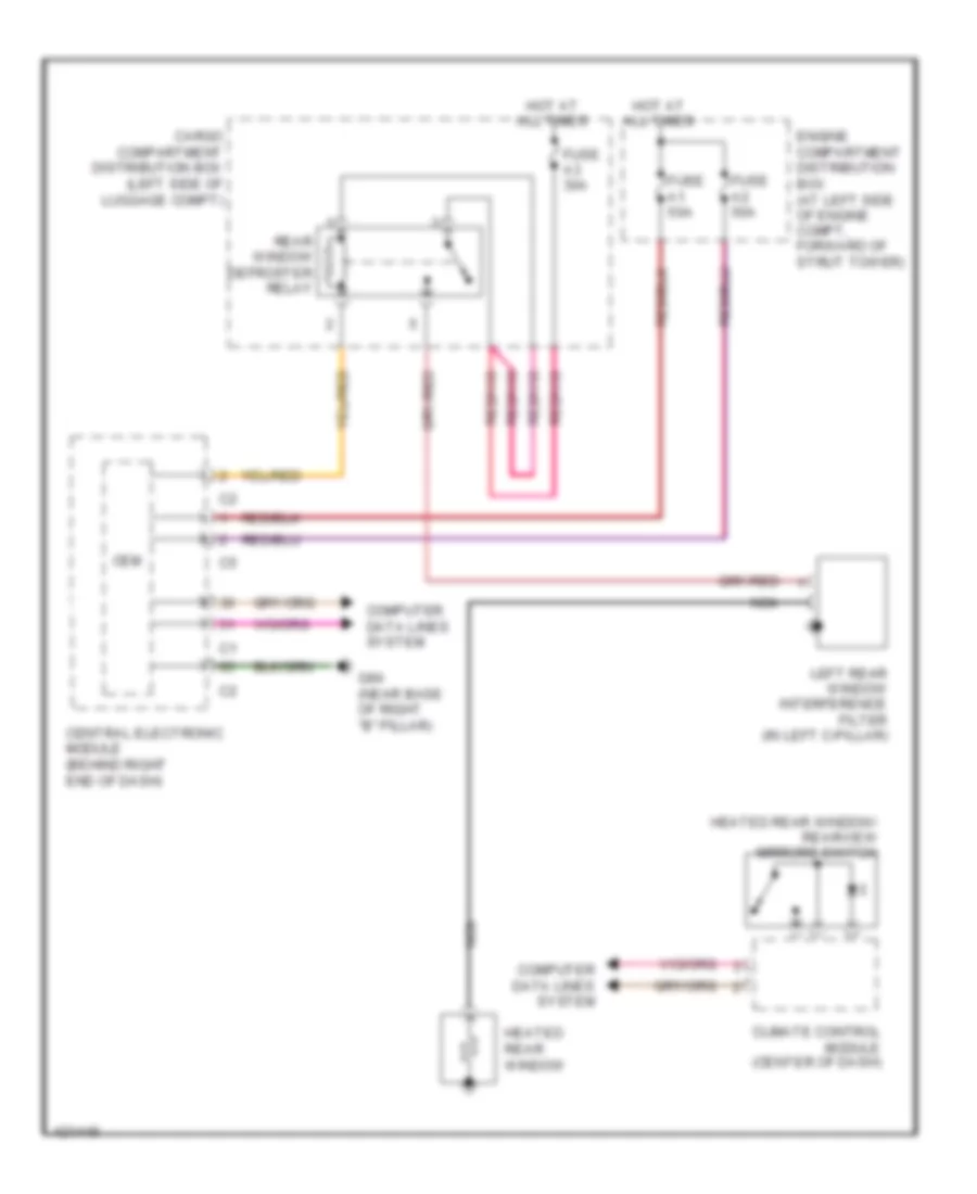
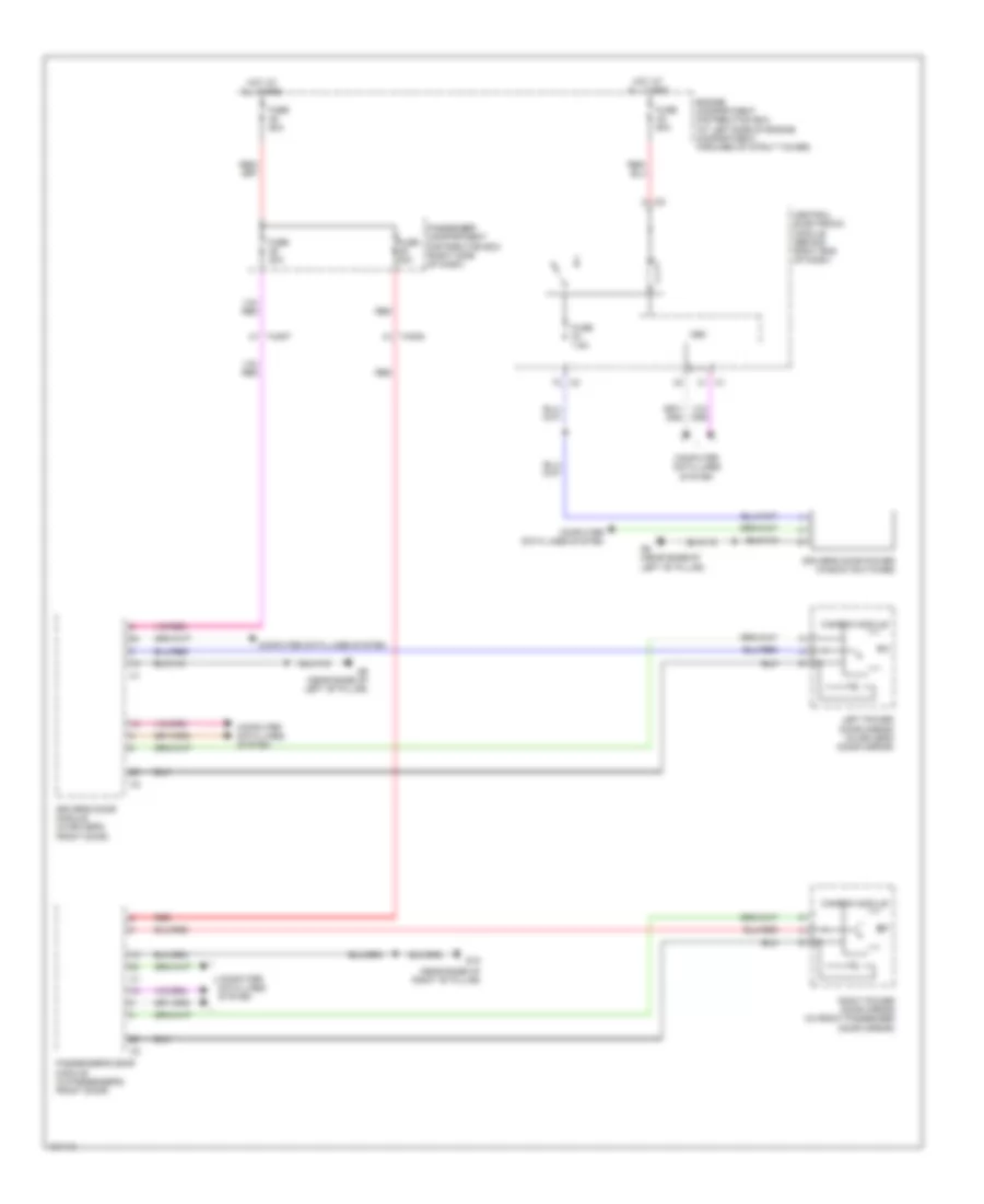
Rear Defogger Wiring Diagram for Volvo S80 T6 2014
List of elements for Rear Defogger Wiring Diagram for Volvo S80 T6 2014:
- Cargo compartment distribution box (left side of luggage compt)
- Cem
- Central electronic module (behind right end of dash)
- Climate control module (center of dash)
- Computer data lines system
- Engine compartment distribution box (at left side of engine compt, forward of strut tower)
- Fuse a1 50a
- Fuse a2 50a
- Fuse a3 30a
- G84 (near base of right "b" pillar)
- Heated rear window
- Heated rear window/ rearview mirrors switch
- Hot at all times
- Left rear window interference filter (in left c-pillar)
- Nca
- Rear window defroster relay
ELECTRONIC POWER STEERING
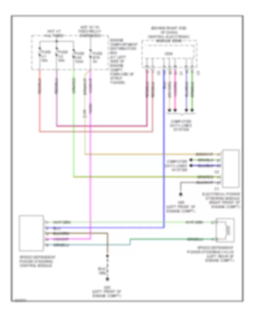
Electronic Power Steering Wiring Diagram for Volvo S80 T6 2014
List of elements for Electronic Power Steering Wiring Diagram for Volvo S80 T6 2014:
- (behind right end of dash) central electronic module (cem)
- 74/301
- Cem
- Computer data lines system
- Electrical power steering module (right front of engine compt)
- Engine compartment distribution box (at left side of engine compt, forward of strut tower)
- Fuse a1 50a
- Fuse a2 50a
- Fuse a44 100a
- Fuse b19 5a
- G93 (left front of engine compt)
- G95 (left front of engine compt)
- Hot at all times
- Hot w/ 15- feed relay energized
- Speed dependent power steering control module
- Speed dependent power steering valve (left rear of engine compt)
ELECTRONIC SUSPENSION
Electronic Suspension Wiring Diagram for Volvo S80 T6 2014
List of elements for Electronic Suspension Wiring Diagram for Volvo S80 T6 2014:
- (base of right "c" pillar) g67
- (in left rear wheelwell) left rear suspension height sensor
- 15-feed feed rear relay
- 74/503
- 74/511
- 74/513
- 74/518
- 74/519
- Cem
- Central electronic module (behind right end of dash)
- Computer data lines system
- Continuously controlled damping switch unit (ccd)
- Engine compartment distribution box (at left side of engine compt forward of strut tower)
- Fuse a1 50a
- Fuse a2 50a
- Fuse c30 5a
- Hot at all times
- Left front four-c acceleration sensor (behind left front bumper)
- Left front four-c shock absorber (in left front wheelwell)
- Left front suspension height sensor (in left front wheelwell)
- Left rear four-c acceleration sensor (left rear corner of luggage compt)
- Left rear four-c shock absorber (in left rear wheelwell)
- Passenger compartment distribution box (right side of dash)
- Red
- Right front four-c acceleration sensor (behind right side of front bumper)
- Right front four-c shock absorber (in right front wheelwell)
- Right front suspension height sensor (in right front wheelwell)
- Right rear four-c shock absorber (in right rear wheelwell)
- Right rear suspension height sensor (in right rear wheelwell)
- Suspension module (sum) (behind center of rear seats)
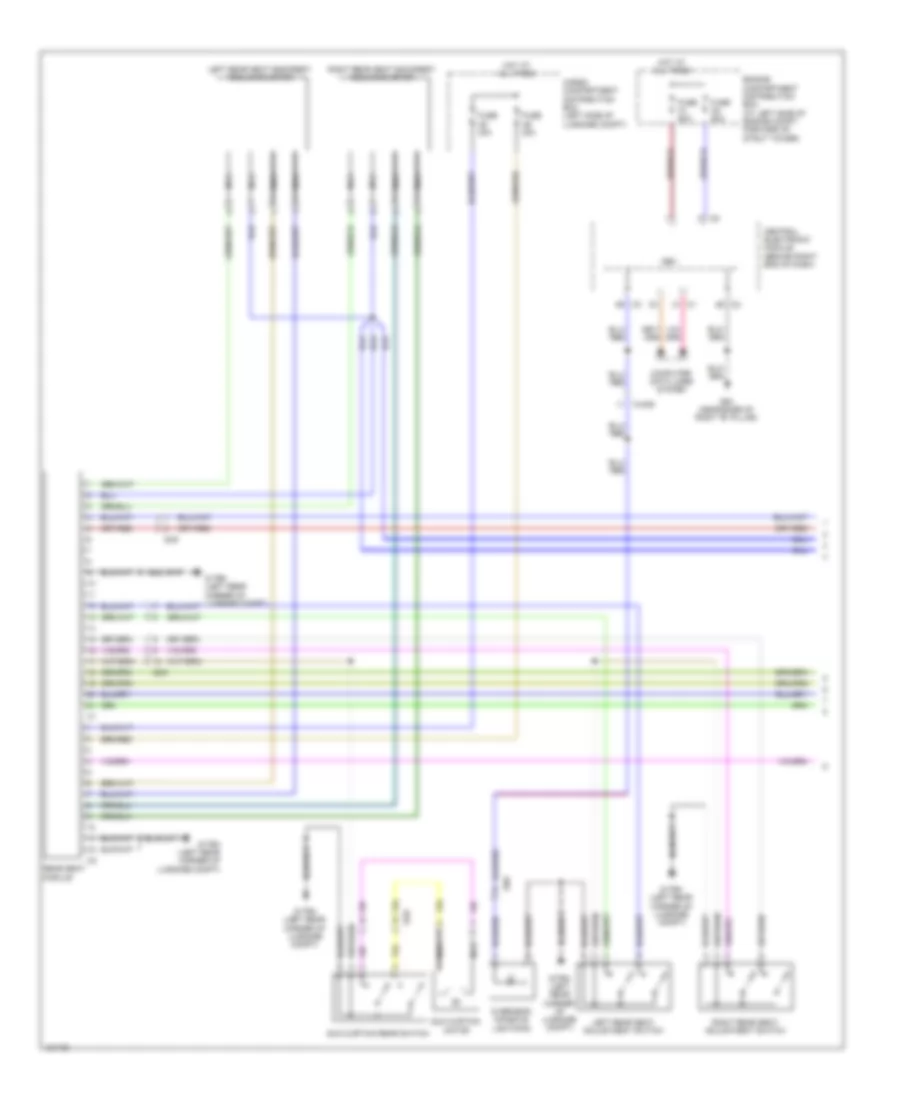
ENGINE PERFORMANCE
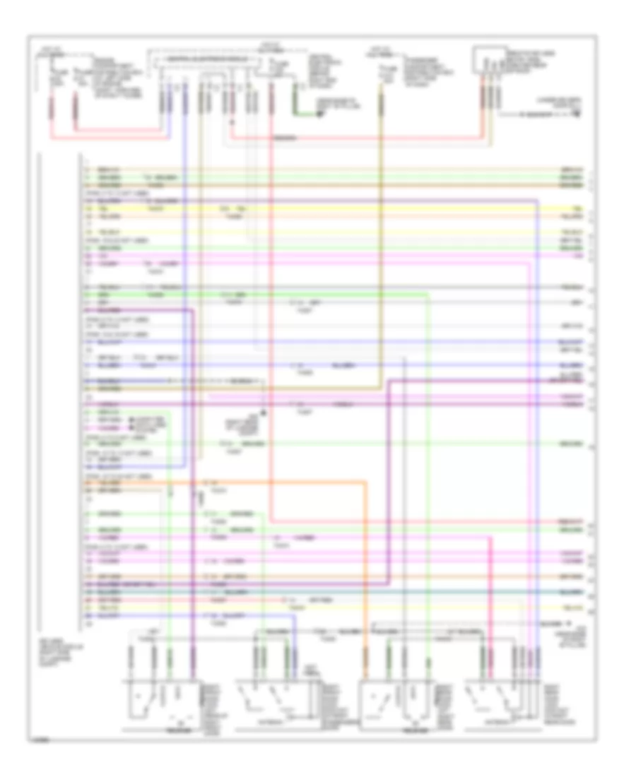
3.0L TURBO
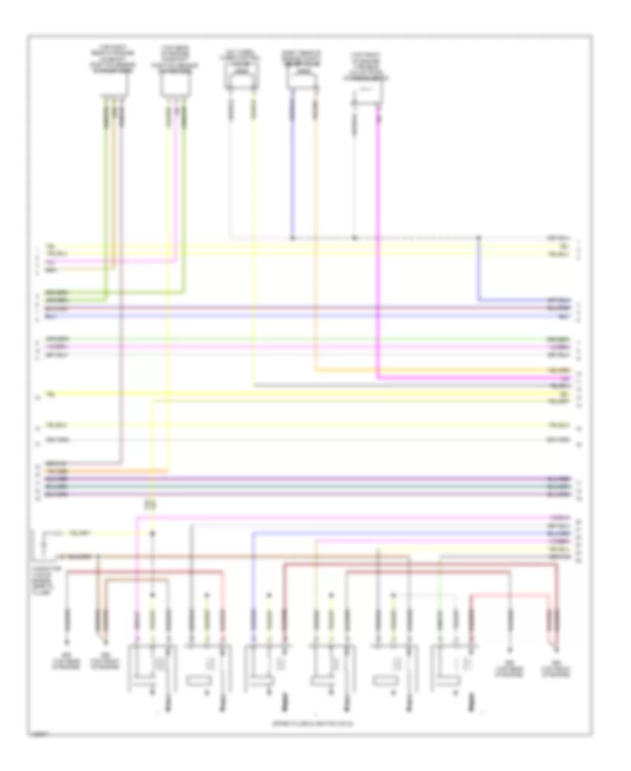
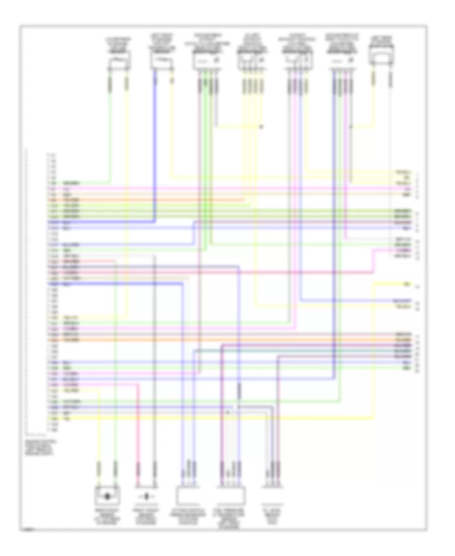
3.0L Turbo, Engine Performance Wiring Diagram (1 of 5) for Volvo S80 T6 2014
List of elements for 3.0L Turbo, Engine Performance Wiring Diagram (1 of 5) for Volvo S80 T6 2014:
- (downstream of right catalytic converter) rear oxygen sensor (bank 1)
- (in left exhaust manifold) front oxygen sensor (bank 1)
- (left front of engine) coolant temperature sensor
- (left rear of engine) evap valve
- (lower rear of engine) impulse sensor
- A10
- A11
- A12
- A13
- A14
- A15
- A16
- A17
- A18
- A19
- A20
- A21
- A22
- A23
- A24
- A25
- A26
- A27
- A28
- A29
- A30
- A31
- A32
- A33
- A34
- A35
- A36
- A37
- A38
- A39
- A40
- A41
- A42
- A43
- A44
- A45
- A46
- A47
- A48
- A49
- A50
- Engine control module (ecm) (left rear of engine compt)
- Front knock sensor (top front of engine)
- Fuel pressure & temperature sensor (left front of engine)
- Intake manifold pressure & temperature sensor (left side of engine)
- Intake manifold pressure sensor (in intake manifold)
- Oil level sensor (in oil pan)
- Rear knock sensor (at top rear of engine)
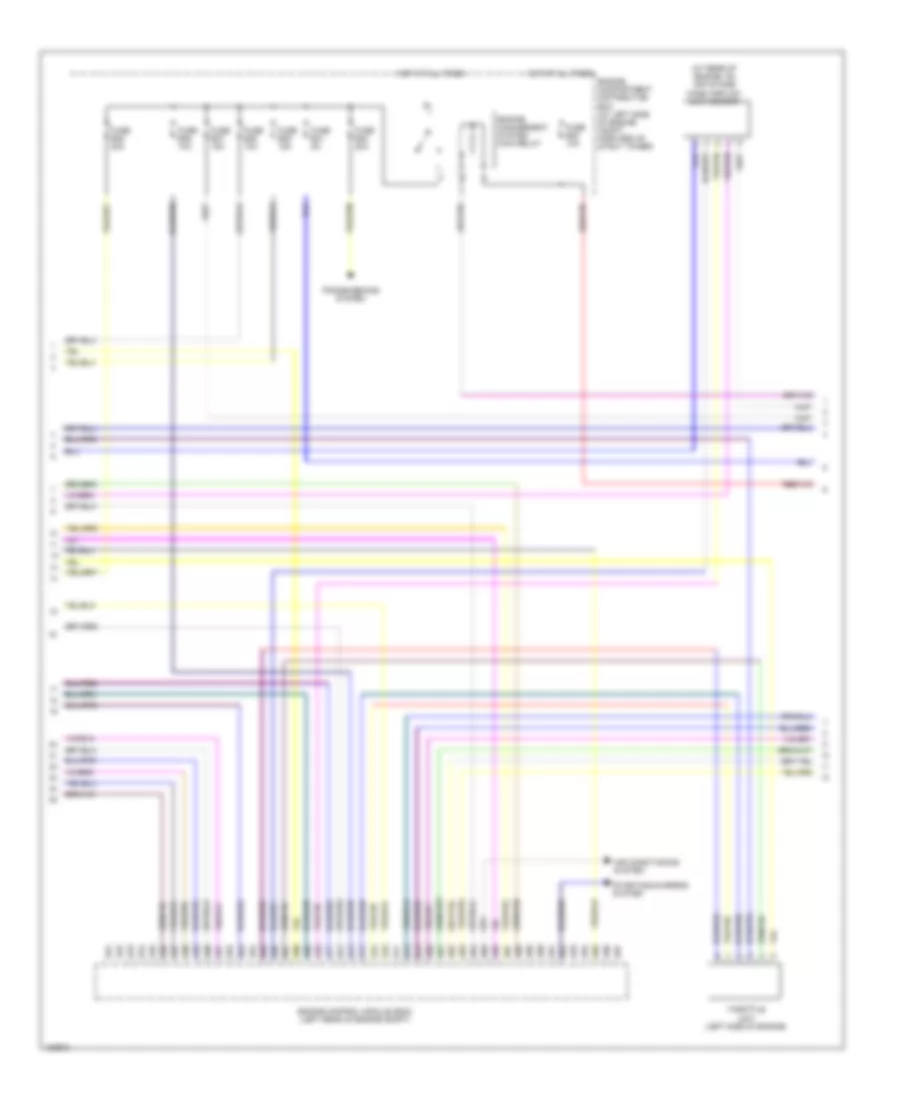
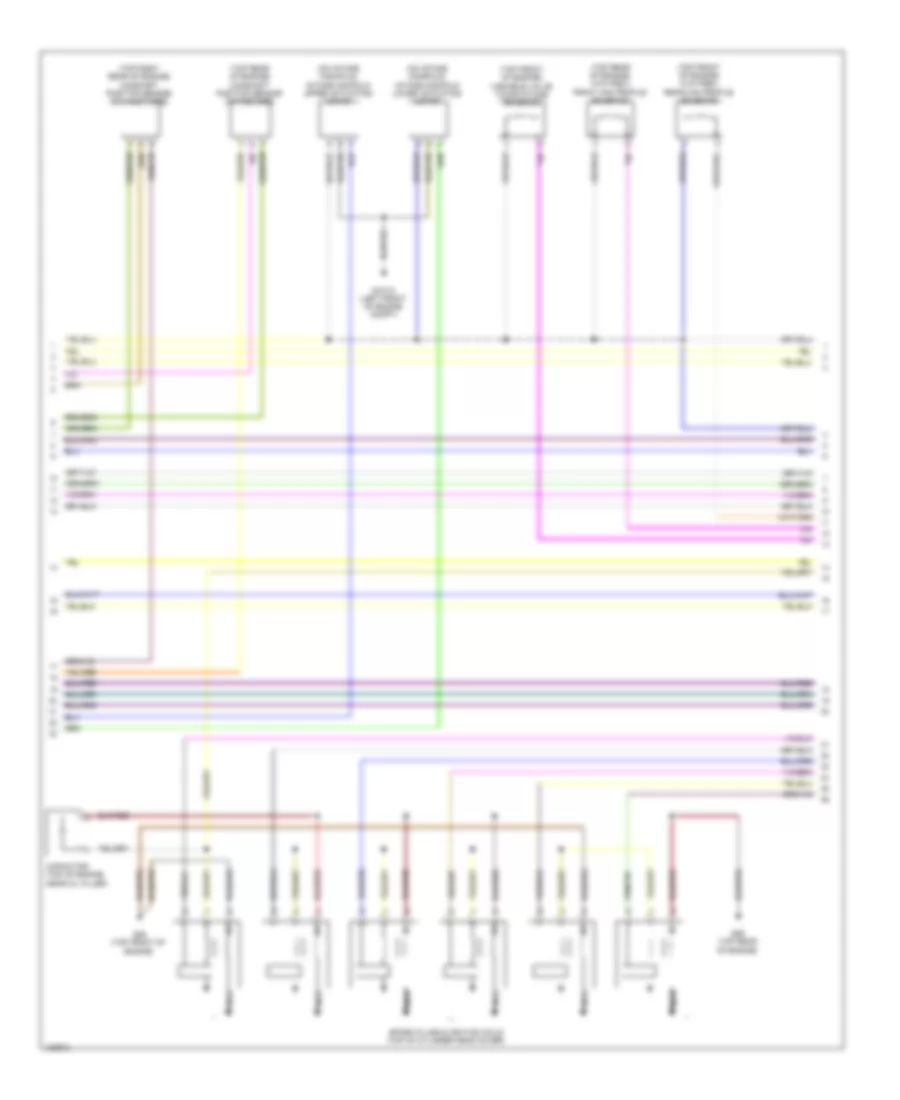
3.0L Turbo, Engine Performance Wiring Diagram (2 of 5) for Volvo S80 T6 2014
List of elements for 3.0L Turbo, Engine Performance Wiring Diagram (2 of 5) for Volvo S80 T6 2014:
- (on turbo) turbo control valve
- (right rear of engine compt) relief valve
- (top front of engine) variable valve timing intake solenoid
- (top rear of engine) camshaft position sensor (intake side)
- (top right rear of engine) camshaft position sensor (exhaust side)
- Capacitor (top of engine, near oil filler)
- G88 (top front of engine)
- G89 (top rear of engine)
- G90 (top front of engine)
- Nca
- Spark plugs & ignition coils
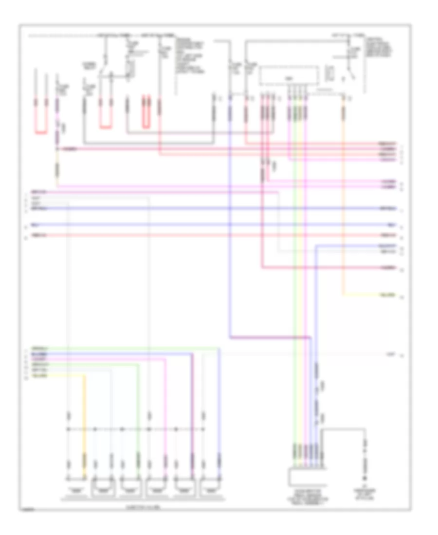
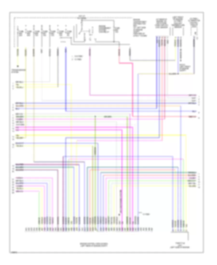
3.0L Turbo, Engine Performance Wiring Diagram (3 of 5) for Volvo S80 T6 2014
List of elements for 3.0L Turbo, Engine Performance Wiring Diagram (3 of 5) for Volvo S80 T6 2014:
- (at rear of engine, on air intake) mass airflow (maf) sensor
- A51
- A52
- A53
- A54
- A55
- A56
- A57
- A58
- A59
- A60
- A61
- A62
- A63
- A64
- A65
- A66
- A67
- A68
- A69
- A70
- A71
- A72
- A73
- A74
- A75
- A76
- A77
- A78
- A79
- A80
- A81
- A82
- A83
- A84
- A85
- A86
- A87
- A88
- A89
- A90
- A91
- A92
- A93
- A94
- A95
- A96
- A97
- Air conditioning system
- Engine compartment distribution box (at left side of engine compt, forward of strut tower)
- Engine control module (ecm) (left rear of engine compt)
- Engine management system main relay
- Fuse b30 10a
- Fuse b35 20a
- Fuse b36 10a
- Fuse b37 15a
- Fuse b38 10a
- Fuse b39 15a
- Fuse b40 20a
- Fuse b41 5a
- Hot at all times
- Starting/charging system
- Throttle unit (left side of engine)
- Transmissions system
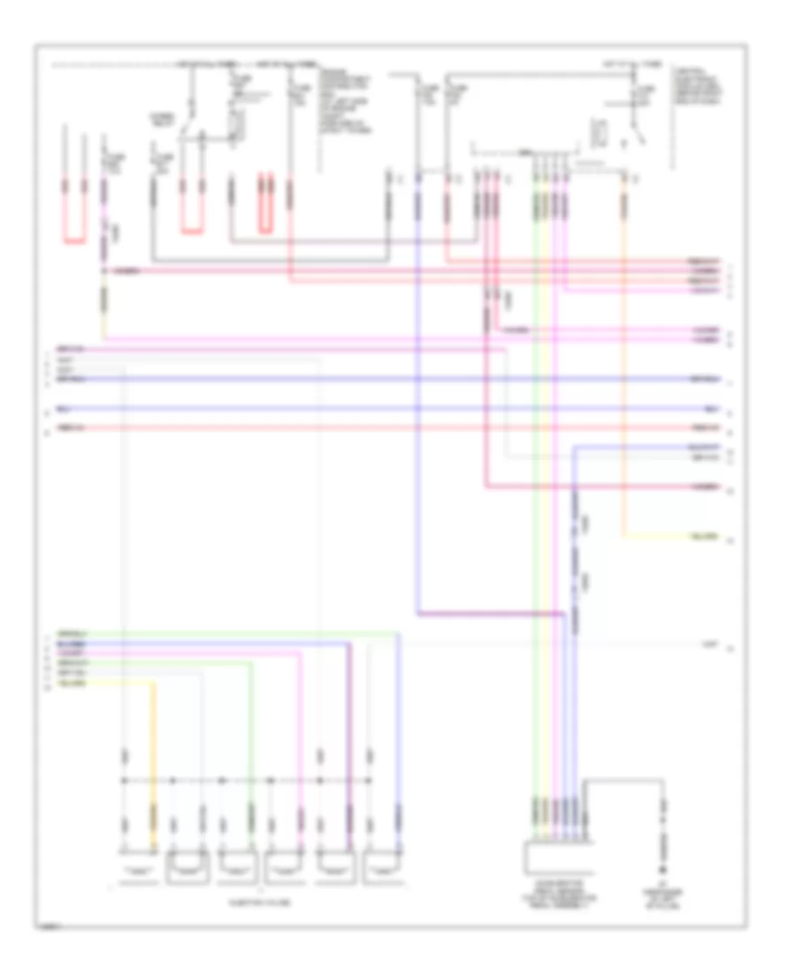
3.0L Turbo, Engine Performance Wiring Diagram (4 of 5) for Volvo S80 T6 2014
List of elements for 3.0L Turbo, Engine Performance Wiring Diagram (4 of 5) for Volvo S80 T6 2014:
- 15-feed relay
- 74/301
- 74/504
- Accelerator pedal sensor (top of accelerator pedal assembly)
- Cem
- Central electronic module (cem) (behind right end of dash)
- Engine compartment distribution box (at left side of engine compt, forward of strut tower)
- Fuse b17 20a
- Fuse b20 10a
- Fuse b27 5a
- Fuse b31 15a
- Fuse f13 20a
- Fuse f20 7.5a
- Fuse f22 5a
- G7 (near base of left "b" pillar)
- Hot at all times
- Injection valves
- Red
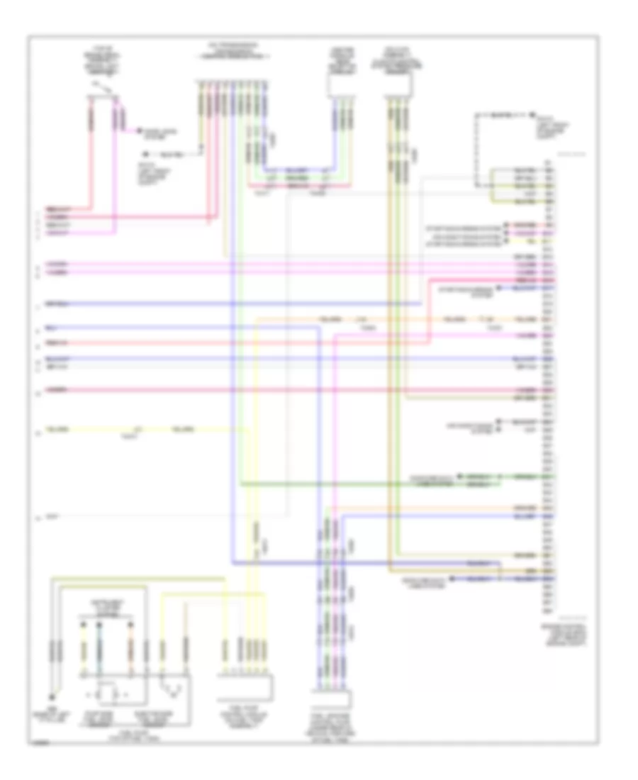
3.0L Turbo, Engine Performance Wiring Diagram (5 of 5) for Volvo S80 T6 2014
List of elements for 3.0L Turbo, Engine Performance Wiring Diagram (5 of 5) for Volvo S80 T6 2014:
- (center console) gear selector module
- (on hvac assembly) climate control system pressure sensor
- (on transmission) transmission control module (tcm)
- (top of brake pedal assembly) brake light contact
- 74/301
- 74/403
- 74/411
- 74/504
- 74/511
- 74/512
- 74/514
- Air conditioning system
- B10
- B11
- B12
- B13
- B14
- B15
- B16
- B17
- B18
- B19
- B20
- B21
- B22
- B23
- B24
- B25
- B26
- B27
- B28
- B29
- B30
- B31
- B32
- B33
- B34
- B35
- B36
- B37
- B38
- B39
- B40
- B41
- B42
- B43
- B44
- B45
- B46
- B47
- B48
- B49
- B50
- B51
- B52
- B53
- B54
- B55
- B56
- B57
- B58
- Computer data lines system
- Door locks system
- Ejector side fuel level sensor
- Engine control module (ecm) (left rear of engine compt)
- Fuel leakage control pump (under rear of vehicle, forward of fuel tank)
- Fuel pump (top of fuel tank)
- Fuel pump control module (on fuel tank assembly)
- G66 (base of left "c" pillar)
- Gxx10 (left front of engine compt)
- Instrument cluster system
- Pump side fuel level sensor
- Starting/charging system
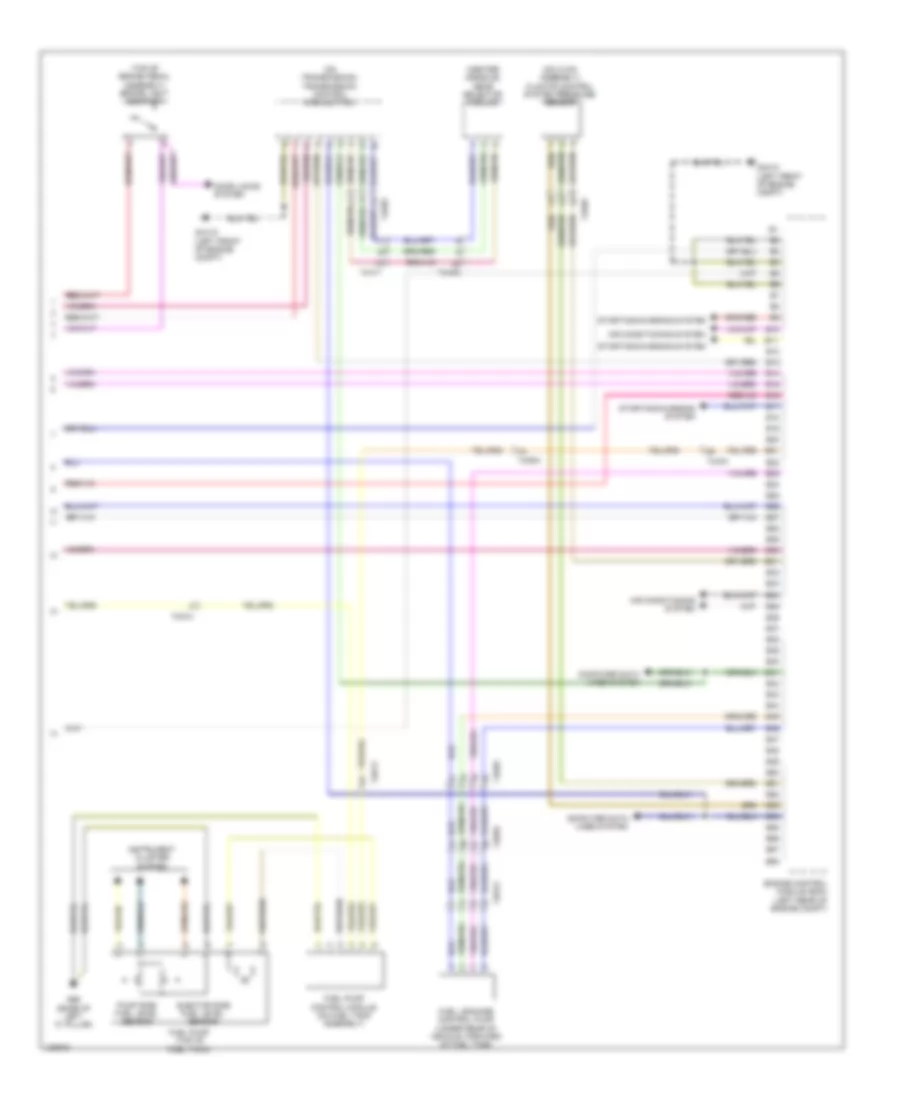
3.2L
3.2L, Engine Performance Wiring Diagram (1 of 5) for Volvo S80 T6 2014
List of elements for 3.2L, Engine Performance Wiring Diagram (1 of 5) for Volvo S80 T6 2014:
- (downstream of right catalytic converter) rear oxygen sensor (bank 1)
- (downstream of right catalytic converter) rear oxygen sensor (bank 2)
- (in left exhaust manifold) front oxygen sensor (bank 1)
- (in right exhaust manifold) (w/o pzev) front oxygen sensor (bank 2)
- (left front of engine) coolant temperature sensor
- (left rear of engine) evap valve
- (lower rear of engine) impulse sensor
- A10
- A11
- A12
- A13
- A14
- A15
- A16
- A17
- A18
- A19
- A20
- A21
- A22
- A23
- A24
- A25
- A26
- A27
- A28
- A29
- A30
- A31
- A32
- A33
- A34
- A35
- A36
- A37
- A38
- A39
- A40
- A41
- A42
- A43
- A44
- A45
- A46
- A47
- A48
- A49
- A50
- Engine control module (ecm) (left rear of engine compt)
- Front knock sensor (top front of engine)
- Fuel pressure & temperature sensor (left front of engine)
- Intake manifold pressure sensor (in intake manifold)
- Oil level sensor (in oil pan)
- Rear knock sensor (at top rear of engine)
3.2L, Engine Performance Wiring Diagram (2 of 5) for Volvo S80 T6 2014
List of elements for 3.2L, Engine Performance Wiring Diagram (2 of 5) for Volvo S80 T6 2014:
- (on intake manifold) intake manifold lower actuating motor
- (on intake manifold) intake manifold upper actuating motor
- (top front of engine) (w/o pzev) rear cam profile solenoid
- (top front of engine) variable valve timing intake solenoid
- (top rear of engine) (w/o pzev) front cam profile solenoid
- (top rear of engine) camshaft position sensor (intake side)
- (top right rear of engine) camshaft position sensor (exhaust side)
- Capacitor (top of engine, near oil filler)
- G88 (top front of engine)
- G89 (top rear of engine)
- Gxx10 (left front of engine compt)
- Nca
- Spark plugs & ignition coils (top of cylinder head cover)
3.2L, Engine Performance Wiring Diagram (3 of 5) for Volvo S80 T6 2014
List of elements for 3.2L, Engine Performance Wiring Diagram (3 of 5) for Volvo S80 T6 2014:
- (at rear of engine, on air intake) mass airflow (maf) sensor
- (left front of engine) (w/ pzev) coolant temperature sensor
- (w/ pzev) alternator control module (acm)
- A51
- A52
- A53
- A54
- A55
- A56
- A57
- A58
- A59
- A60
- A61
- A62
- A63
- A64
- A65
- A66
- A67
- A68
- A69
- A70
- A71
- A72
- A73
- A74
- A75
- A76
- A77
- A78
- A79
- A80
- A81
- A82
- A83
- A84
- A85
- A86
- A87
- A88
- A89
- A90
- A91
- A92
- A93
- A94
- A95
- A96
- A97
- Air conditioning system
- Engine compartment distribution box (at left side of engine compt, forward of strut tower)
- Engine control module (ecm) (left rear of engine compt)
- Engine management system main relay
- Fuse b30 10a
- Fuse b35 20a
- Fuse b36 10a
- Fuse b37 15a
- Fuse b38 10a
- Fuse b39 15a
- Fuse b40 20a
- Fuse b41 5a
- Gxx10 (left front of engine compt)
- Hot at all times
- Lin
- Throttle unit (left side of engine)
- Transmissions system
- W/ pzev
- W/o pzev
3.2L, Engine Performance Wiring Diagram (4 of 5) for Volvo S80 T6 2014
List of elements for 3.2L, Engine Performance Wiring Diagram (4 of 5) for Volvo S80 T6 2014:
- 15-feed relay
- 74/301
- 74/504
- Accelerator pedal sensor (top of accelerator pedal assembly)
- Cem
- Central electronic module (cem) (behind right end of dash)
- Engine compartment distribution box (at left side of engine compt, forward of strut tower)
- Fuse b17 20a
- Fuse b20 10a
- Fuse b27 5a
- Fuse b31 15a
- Fuse f13 20a
- Fuse f20 7.5a
- Fuse f22 5a
- G7 (near base of left "b" pillar)
- Hot at all times
- Injection valves
- Red
3.2L, Engine Performance Wiring Diagram (5 of 5) for Volvo S80 T6 2014
List of elements for 3.2L, Engine Performance Wiring Diagram (5 of 5) for Volvo S80 T6 2014:
- (center console) gear selector module
- (on hvac assembly) climate control system pressure sensor
- (on transmission) transmission control module (tcm)
- (top of brake pedal assembly) brake light contact
- 74/301
- 74/403
- 74/411
- 74/504
- 74/511
- 74/512
- 74/514
- Air conditioning system
- B10
- B11
- B12
- B13
- B14
- B15
- B16
- B17
- B18
- B19
- B20
- B21
- B22
- B23
- B24
- B25
- B26
- B27
- B28
- B29
- B30
- B31
- B32
- B33
- B34
- B35
- B36
- B37
- B38
- B39
- B40
- B41
- B42
- B43
- B44
- B45
- B46
- B47
- B48
- B49
- B50
- B51
- B52
- B53
- B54
- B55
- B56
- B57
- B58
- Computer data lines system
- Door locks system
- Ejector side fuel level sensor
- Engine control module (ecm) (left rear of engine compt)
- Fuel leakage control pump (under rear of vehicle, forward of fuel tank)
- Fuel pump (top of fuel tank)
- Fuel pump control module (on fuel tank assembly)
- G66 (base of left "c" pillar)
- Gxx10 (left front of engine compt)
- Instrument cluster system
- Pump side fuel level sensor
- Starting/charging system
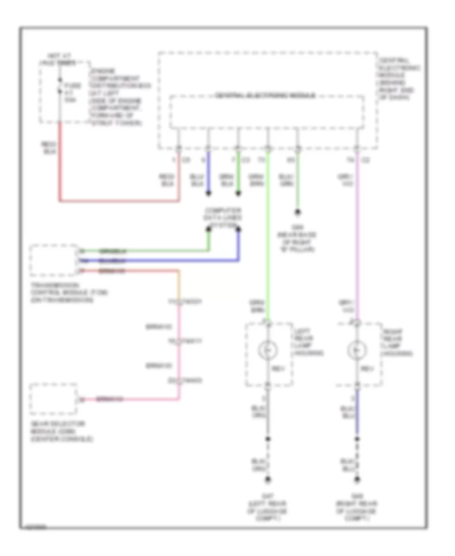
EXTERIOR LIGHTS
Backup Lamps Wiring Diagram for Volvo S80 T6 2014
List of elements for Backup Lamps Wiring Diagram for Volvo S80 T6 2014:
- 74/301
- 74/403
- 74/411
- Central electronic module
- Central electronic module (behind right end of dash)
- Computer data lines system
- Engine compartment distribution box (at left side of engine compartment, forward of strut tower)
- Fuse a1 50a
- G47 (left rear of luggage compt)
- G48 (right rear of luggage compt)
- G84 (near base of right "b" pillar)
- Gear selector module (gsm) (center console)
- Hot at all times
- Left rear lamp housing
- Rev
- Right rear lamp housing
- Transmission control module (tcm) (on transmission)
Exterior Lamps Wiring Diagram (1 of 2) for Volvo S80 T6 2014
List of elements for Exterior Lamps Wiring Diagram (1 of 2) for Volvo S80 T6 2014:
- (4)
- 74/411
- 74/601
- Auxiliary brake light
- Auxiliary lights (accessory) relay (right front of engine compartment)
- Auxiliary lights switch
- Brake light contact (top of brake pedal assembly)
- Central electronic module
- Central electronic module (behind right end of dash)
- Climate control module (ccm) (center of dash)
- Computer data lines system
- Engine compartment distribution box (at left side of engine compartment, forward of strut tower)
- Fuse a1 50a
- Fuse a2 50a
- Fuse b23 5a
- Fuse b28 20a
- Fuse f22 5a
- G-al (right front of engine compartment)
- G10 (under driver's door sill)
- G83 (under driver's door sill)
- G84 (near base of right "b" pillar)
- G93 (left front of engine compartment)
- G94 (right front of engine compartment)
- Hazard warning flasher switch
- Hot at all times
- Keyless vehicle module (kvm) (if equipped) (right side of luggage compartment)
- Left front auxiliary light
- Left front lamp housing
- Light switch module (lsm)
- Pos
- Red
- Right front auxiliary light
- Right front lamp housing
- Solid state
- Turn
Exterior Lamps Wiring Diagram (2 of 2) for Volvo S80 T6 2014
List of elements for Exterior Lamps Wiring Diagram (2 of 2) for Volvo S80 T6 2014:
- 74/507
- 74/508
- Backup lamps circuit
- Computer data lines system
- Direction indicator
- Door locks system
- Driver information module (dim) (left side of dash)
- Driver's door module (ddm) (in driver's front door)
- Fog
- Fuse c8 20a
- Fuse c9 20a
- G15 (near base of right "b" pillar)
- G47 (left rear of luggage compartment)
- G48 (right rear of luggage compartment)
- G6 (near base of left "b" pillar)
- G65 (base of left "c" pillar)
- Hot at all times
- Left front door mirror lighting
- Left power door mirror (in driver's door mirror)
- Left rear lamp housing/ side marker lamp & left tail lamp
- License plate lighting
- Passenger compartment distribution box (right side of dash)
- Passenger door module (pdm) (in passenger front door)
- Pos
- Red
- Rev
- Right front door mirror lighting
- Right power door mirror (in front passenger door mirror)
- Right rear lamp housing/ side marker lamp & right tail lamp
- Steering wheel module (swm) (in steering column)
- Stop
- Trailer tow circuit
- Trunk handle switch
- Turn
Trailer Tow Wiring Diagram, 4-Pin for Volvo S80 T6 2014
List of elements for Trailer Tow Wiring Diagram, 4-Pin for Volvo S80 T6 2014:
- (or pnk)
- (or red)
- 4-pin tow hitch cable harness (under center of rear bumper)
- 4x/110c2
- Assistant camera
- Brake light contact (top of brake pedal assembly)
- Cargo compartment distribution box (left side of luggage compt)
- Central electronic module
- Central electronic module (behind right end of dash)
- Computer data lines system
- Engine compartment distribution box (at left side of engine compt, forward of strut tower)
- Fuse a1 50a
- Fuse a11 40a
- Fuse a2 50a
- Fuse c28 5a
- Fuse f22 5a
- G-trm (left rear corner of luggage compt)
- G47 (left rear of luggage compt)
- Hot at all times
- Hot w/ 15 feed rear relay energized
- Keyless vehicle module (kvm) (if equipped) (right side of luggage compt)
- Left rear lamp housing
- Passenger compartment distribution box (right side of dash)
- Stop
- Trailer module (trm) (left rear of luggage compt)
- W/ parking
Trailer Tow Wiring Diagram, 7-Pin for Volvo S80 T6 2014
List of elements for Trailer Tow Wiring Diagram, 7-Pin for Volvo S80 T6 2014:
- (or pnk)
- (or red)
- 4x/110c2
- 7-pin tow hitch cable harness (under center of rear bumper)
- Brake light contact (top of brake pedal assembly)
- Cargo compartment distribution box (left side of luggage compt)
- Central electronic module
- Central electronic module (behind right end of dash)
- Computer data lines system
- Electrical brake controller
- Engine compartment distribution box (at left side of engine compartment, forward of strut tower)
- Fuse a1 50a
- Fuse a11 40a
- Fuse a2 50a
- Fuse c28 5a
- Fuse f22 5a
- G-trm (left rear corner of luggage compt)
- G47 (left rear of luggage compt)
- Hot at all times
- Hot w/ 15 feed rear relay energized
- Keyless vehicle module (kvm) (if equipped) (right side of luggage compt)
- Left rear lamp housing
- Passenger compartment distribution box (right side of dash)
- Stop
- Trailer module (trm) (left rear of luggage compt)
- W/ parking assistant camera
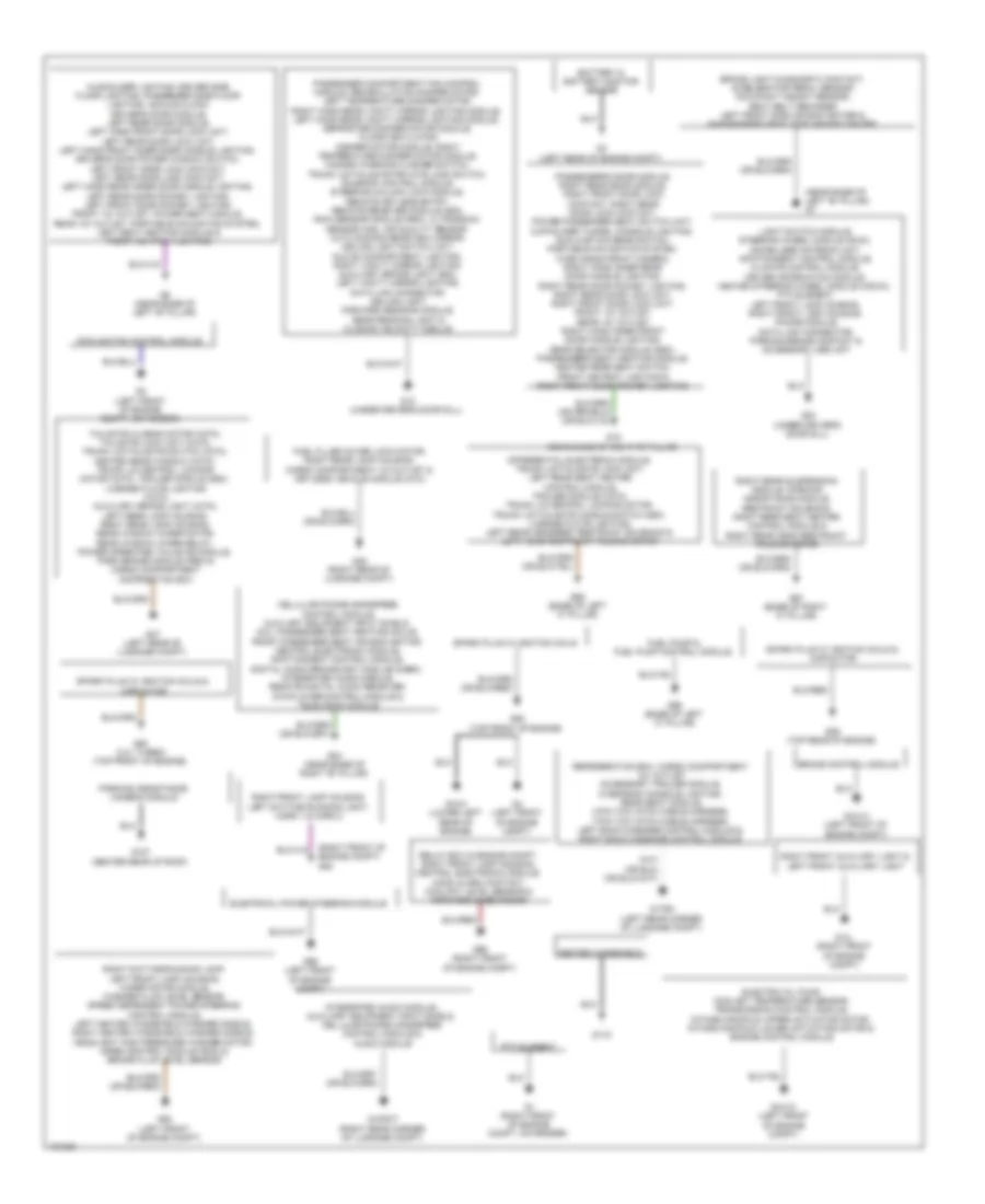
GROUND DISTRIBUTION
Ground Distribution Wiring Diagram for Volvo S80 T6 2014
List of elements for Ground Distribution Wiring Diagram for Volvo S80 T6 2014:
- (near base of left "b" pillar) g7
- (right front of engine compt) g94
- Battery & battery monitor sensor
- Brake control module
- Brake light diagnostic contact, accelerator pedal sensor, occupant weight sensor, seat belt reminder, left front side air bag igniter & passenger's seat side air bag igniter
- Cellular phone handsfree control module, auxilary equipment input shield, acu, passenger seat heating moule, front passenger seat air bag ignitor, central electronic module, infotainment control module, digital audio broadcast modlue (dabm), integrated audio module, remote digital audio receiver, dvd player/control module & television module
- Cooling fan control module
- Differential electronic module, trunk lid/tailgate lock unit, left rear seat heater control module, trailer module (xc70), trunk lid central locking motor, trunk lid/tailgate handle switch (s80), license plate lighting, left rear headrest restraint solenoid & left head restraint folding motor
- Electric oil pump, coolant temperature sensor, transmission control module, intake manifold upper actuating motor, intake manifold lower actuating motor & engine control module
- Electrical power steering module
- Fuel filler cover lock motor, right rear lamp housing, cargo compartment 12v outlet & keyless vehicle module (kvm)
- Fuel pump & fuel pump control module
- G-al (right front of engine compt)
- G-infot (right rear corner of luggage compt)
- G-trm (left rear corner of luggage compt)
- G1 (right front of engine compt, on fender)
- G10 (under driver's door sill)
- G107 (center rear of roof)
- G115
- G15 (near base of right "b" pillar)
- G2 (left front of engine compt, on fender)
- G3 (left rear of engine compt)
- G4 (left front of engine compt)
- G47 (left rear of luggage compt)
- G48 (right rear of luggage compt)
- G6 (near base of left "b" pillar)
- G65 (base of left "c" pillar)
- G66 (base of left "c" pillar)
- G67 (base of right "c" pillar)
- G83 (under driver's door sill)
- G84 (near base of right "b" pillar)
- G88 (top front of engine)
- G89 (top rear of engine)
- G90 (3.0l turbo) (top front of engine)
- G93 (left front of engine compt)
- G95 (left front of engine compt)
- G96 (right front of engine compt)
- Gxx10 (left front of engine compt)
- Gxx14 (left front of engine compt)
- Gxx4 (lower left rear of engine)
- Heated windshield
- Integrated audio module, auxiliary equipment input shield, cellular phone handsfree control module & audio module
- Light switch module, steering wheel module (swm), immobilizer antenna unit, infotainment control module, climate control module, driver information module, heated steering wheel module (hswc), ptc element, left front lamp housing, right front lamp housing, phone module, data link connector, parking brake contact & accessory usb unit
- Mugholder lighting, driver side floor lighting, passenger side floor lighting, analog clock, driver's door module, left rear door module, left hand front door lock unit, left rear door lock unit, left hand front inner door handle lighting, driver's door power window switch, left front door lock contact, left rear door lock contact, left hand rear inner door handle lighting, left rear door pocket lighting, left front door pocket lighting, front 12v outlet, power seat module, rear 12v outlet, portable navigation system, left seat heating module & front ashtray lighting
- Parking assistance camera module
- Passenger compartment fan control module, recirculation damper motor, left temperature damper motor, right hand rear vanity mirror lighting module, left hand rear vanity mirror lighting module, defroster damper motor module, floor/ventilation damper motor module, right temperature damper motor module, hazard warning flasher switch, trunk lid/tailgate private lock switch, sunroof control module, steering column lock module, remote keyless entry, remote receiver module (s80), rain sensor module (rsm), ultrasonic sensor (ims), air quality sensor, auto dimming rearview mirror, ceiling light switch unit, glove compartment lighting, right vanity mirror lighting, auxiliary brake light (s80), left vanity mirror lighting, data link connector, ceiling light, forward sensing module, rear reading light & closing velocity module
- Passenger's door module, right rear door module, right front door lock contact, right rear door lock contact, power passenger seat switch unit, cupholder tunnel console lighting, sun curtain rear switch, portable navigation system, wide angle front camera, right hand inner rear door handle lighting, right rear door pocket lighting, right rear door lock unit, right front door lock unit, front 12v outlet, rear 12v outlet, right hand inner front door handle lighting, gear selector module (gsm), passenger's seat heating module, heated rear seat switch, front ashtray lighting & right front door pocket lighting
- Ptc element
- Refrigeration box, cargo compartment 12v outlet, accessory trailer module, overhead console lighting, rear seat module, 4-pin tow hitch cable harness, 7-pin tow hitch cable harness, left back massage control module & right back massage control module
- Relay box in engine compt, right front lamp housing, central electronic module, hood alarm contact, coolant level sensor & forward-aimed radar
- Right daytime running lamp, left front lamp housing, wiper motor module, washer fluid level sensor, speed dependent power steering control module, left heated windshield washer nozzle, right heated windshield washer nozzle, headlight high pressure washer motor, siren control module (scm) & brake fluid level sensor
- Right front auxiliary light & left front auxiliary light
- Right front lamp housing, left daytime running light, horn 1 & horn 2
- Right rear suspension module, parking assistance module, restraint solenoid, right rear seat heater control module & right rear head restraint folding motor
- Spark plug w/ ignition coils
- Spark plug w/ ignition coils & capacitor
- Tailgate closing motor (xc70), tailgate lock unit (xc70), trunk lid/tailgate switch (xc70), heated rear window (xc70), trunk lid central locking motor (xc70), trailer module (s80), license plate lighting (xc70), auxiliary brake light (xc70), left rear lamp housing, right rear lamp housing, rear window wiper motor, rear window wiper relay, power operated tailgate module, park brake module (pbm) & cargo compartment distribution box
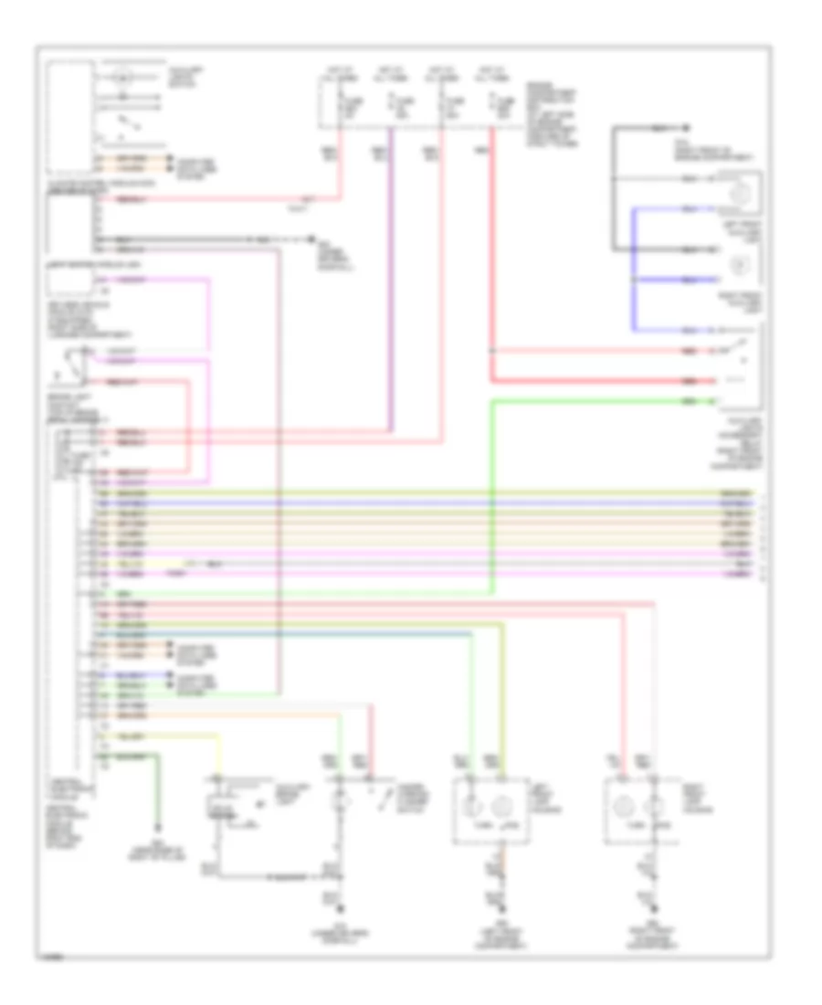
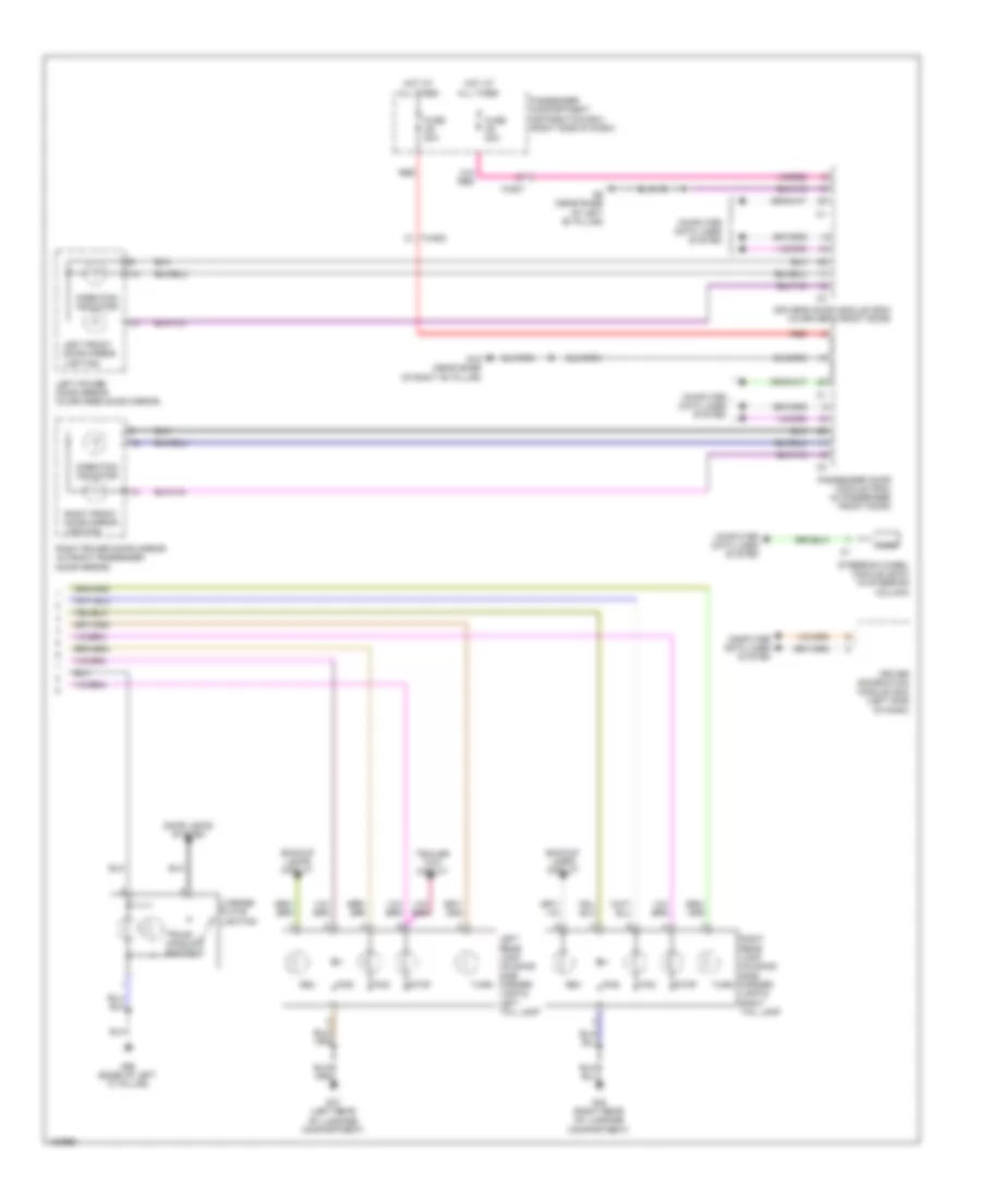
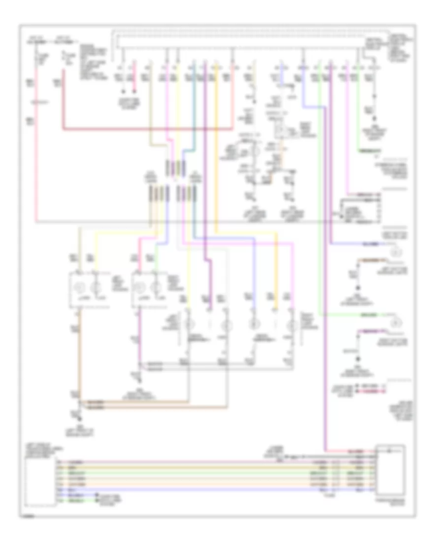
HEADLIGHTS
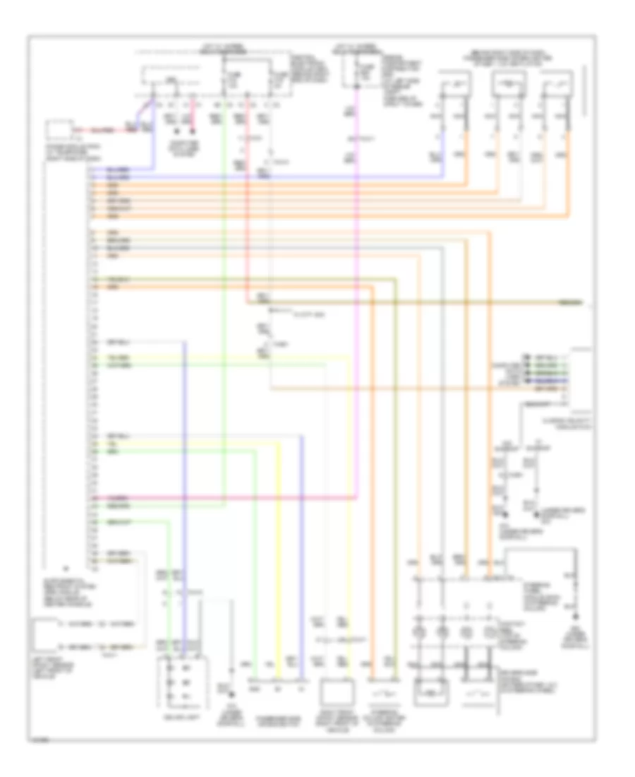
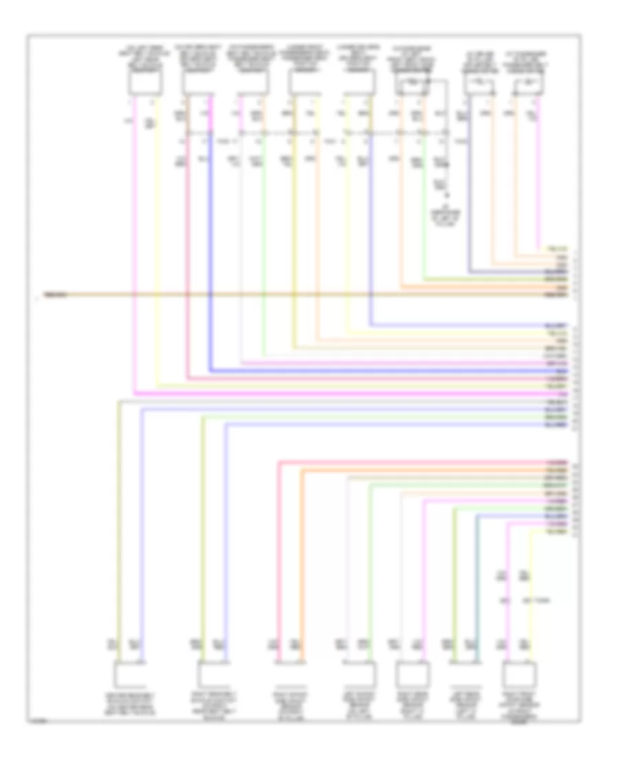
Headlamps Wiring Diagram for Volvo S80 T6 2014
List of elements for Headlamps Wiring Diagram for Volvo S80 T6 2014:
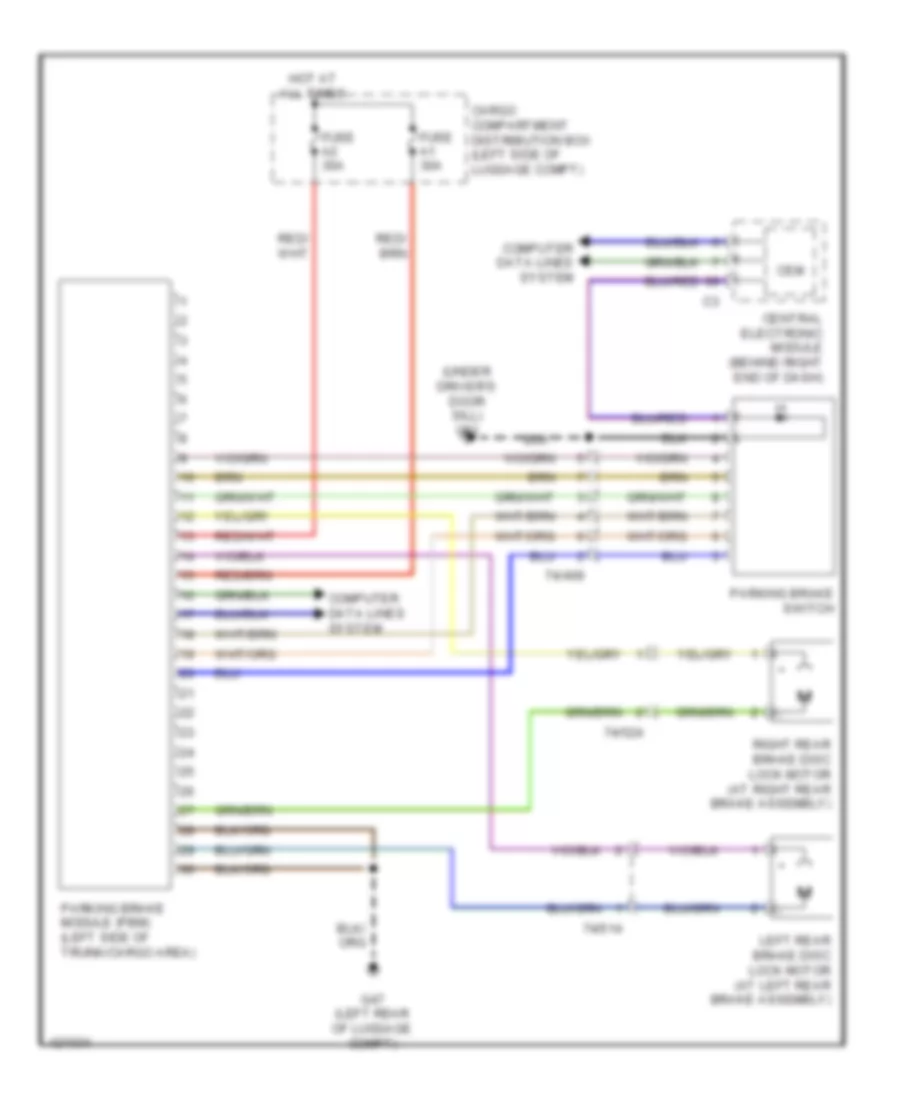
- (left side of trunk/cargo area) parking brake module (pbm)
- (s80)
- (under driver's door sill) g83
- (xc70)
- (xc70) c1
- 74/409
- 74/411
- 74/602
- Central electronic module
- Central electronic module (cem) (behind right end of dash)
- Computer data lines system
- Driver information module (dim) (left side of dash)
- Engine compartment distribution box (at left side of engine compt, forward of strut tower)
- Fog light
- Fuse a1 50a
- Fuse b23 5a
- G47 (left rear of luggage compt)
- G48 (right rear of luggage compt)
- G93 (left front of engine compt)
- G94 (right front of engine compt)
- G96 (right front of engine compt)
- High
- Hot at all times
- Left daytime running lights
- Left front lamp housing
- Left rear lamp housing
- Light switch module (lsm)
- Low
- Parking brake switch
- Right daytime running lights
- Right front lamp housing
- Right rear lamp housing
- S80
- Steering wheel module (swm) (in steering column)
- W/ xenon lamps
- W/o xenon lamps
- Xc70
- Xenon low/high
Headlamps Leveling Wiring Diagram for Volvo S80 T6 2014
List of elements for Headlamps Leveling Wiring Diagram for Volvo S80 T6 2014:
- (in right front wheelwell) (w/o four-c) right front suspension height sensor
- (right front of engine compt) g96
- 15-feed relay
- 74/511
- 74/512
- 74/513
- 74/519
- Central electronic module (cem)
- Central electronic module (cem) (behind right end of dash)
- Computer data lines system
- Contact reel (top of steering column)
- Electronic suspension system
- Engine compartment distribution box (at left side of engine compt, forward of strut tower)
- Fuse a1 50a
- Fuse a2 50a
- Fuse b16 10a
- Fuse b27 5a
- G93 (left front of engine compt)
- G96 (right front of engine compt)
- Hot at all times
- Left front lamp housing
- Left front suspension height sensor (w four-c) (in left front wheelwell)
- Left hand headlight level adjustment motor
- Left rear suspension height sensor (w/ four-c) (in left rear wheelwell)
- Right front lamp housing
- Right front suspension height sensor (w four-c) (in right front wheelwell)
- Right hand headlight level adjustment motor
- Right rear suspension height sensor (w/ four-c) (in right rear wheelwell)
- Right rear suspension height sensor (w/o four-c) (in right rear wheelwell)
- Solar sensor, twilight sensor & indicator alarm (top center of dash)
- Steering angle sensor
- Steering wheel angle sensor module (sas)
- Steering wheel module (swm) (in steering column)
- Suspension module (sum) (behind center of rear seats)
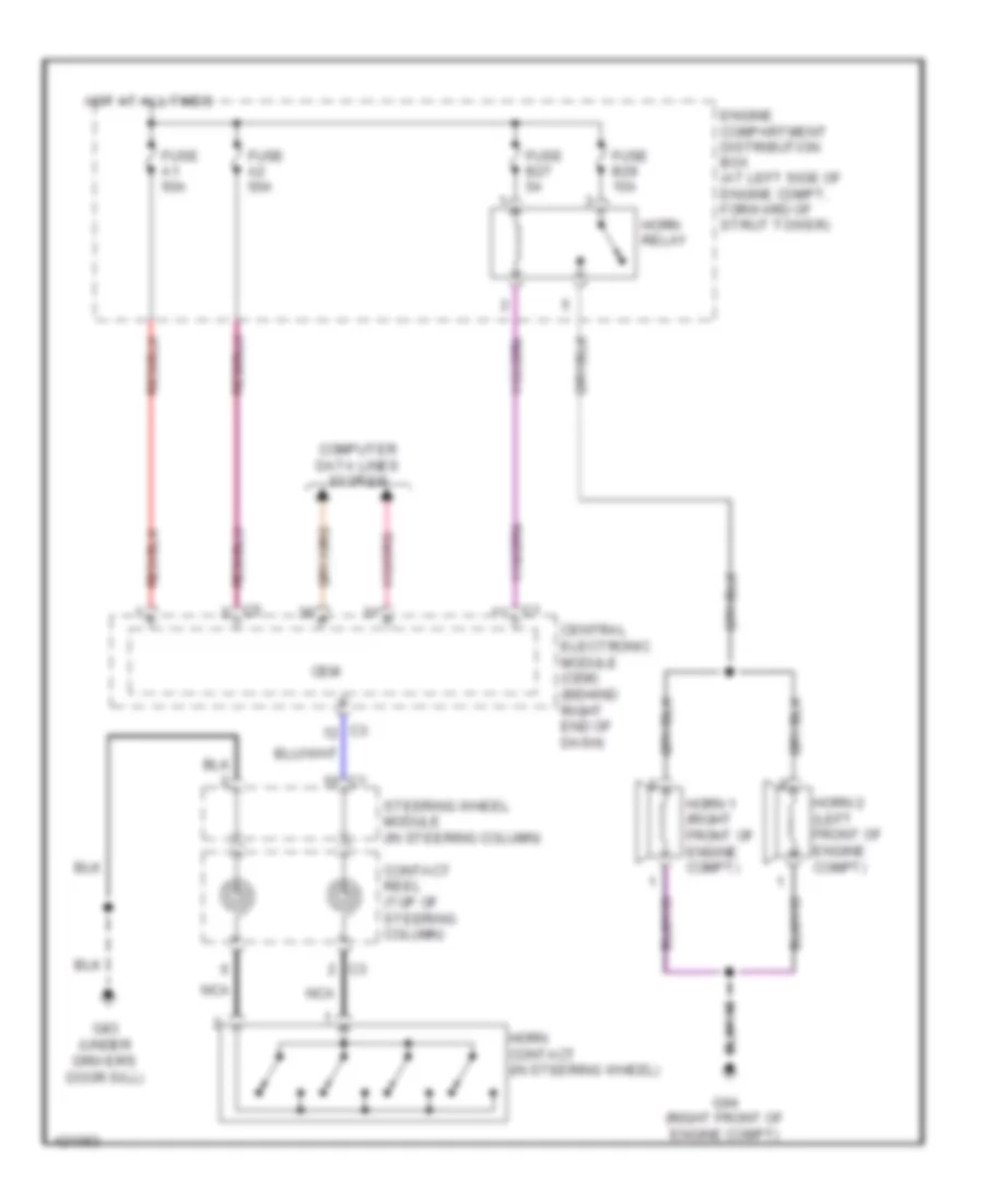
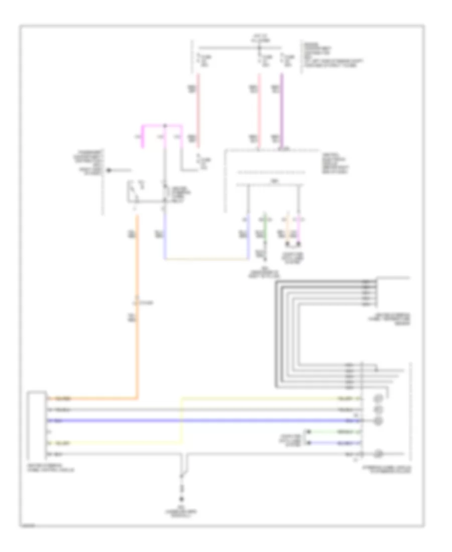
HORN
Horn Wiring Diagram for Volvo S80 T6 2014
List of elements for Horn Wiring Diagram for Volvo S80 T6 2014:
- Cem
- Central electronic module (cem) (behind right end of dash)
- Computer data lines system
- Contact reel (top of steering column)
- Engine compartment distribution box (at left side of engine compt, forward of strut tower)
- Fuse a1 50a
- Fuse a2 50a
- Fuse b27 5a
- Fuse b29 15a
- G83 (under driver's door sill)
- G94 (right front of engine compt)
- Horn 1 (right front of engine compt)
- Horn 2 (left front of engine compt)
- Horn contact (in steering wheel)
- Horn relay
- Hot at all times
- Nca
- Steering wheel module (in steering column)
INSTRUMENT CLUSTER
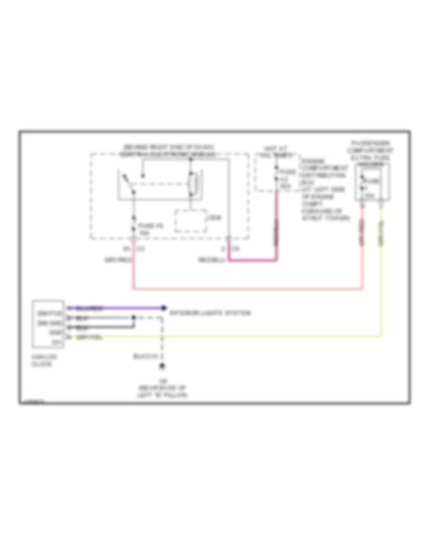
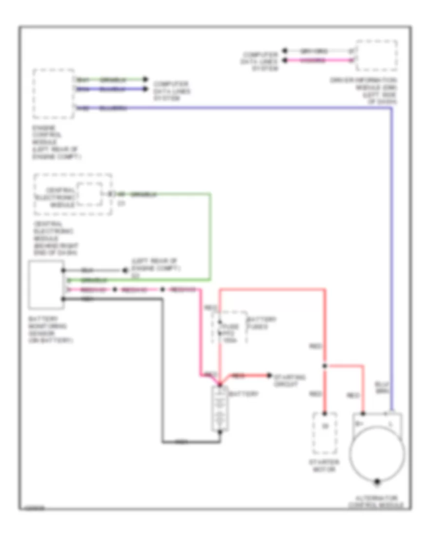
Clock Wiring Diagram for Volvo S80 T6 2014
List of elements for Clock Wiring Diagram for Volvo S80 T6 2014:
- (behind right end of dash) central electronic module
- 30+
- Analog clock
- Cem
- Dim gnd
- Dim pos
- Engine compartment distribution box (at left side of engine compt, forward of strut tower)
- Fuse 15a
- Fuse a2 50a
- Fuse f5 10a
- G6 (near base of left "b" pillar)
- Gnd
- Hot at all times
- Interior lights system
- Passenger compartment extra fuse holder
Driver Information System Wiring Diagram for Volvo S80 T6 2014
List of elements for Driver Information System Wiring Diagram for Volvo S80 T6 2014:
- 74/301
- 74/511
- B14
- B30
- B41
- B54
- Brake fluid level sensor (on brake master cylinder reservoir)
- Central electronic module
- Central electronic module (cem) (behind right end of dash)
- Computer data lines system
- Coolant level sensor (at right side of engine compt, in coolant tank)
- Driver information module (dim) (left side of dash)
- Ejector side fuel level sensor
- Engine control module (ecm) (left rear of engine compt)
- Fuel pump (top of fuel tank)
- Fuse f4 5a
- G66 (base of left "c" pillar)
- G83 (under driver's door sill)
- G93 (left front of engine compt)
- G96 (right front of engine compt)
- Hot at all times
- Park brake module (left side of trunk/cargo area)
- Pump side fuel level sensor
- Transmission control module (tcm) (on transmission)
INTERIOR LIGHTS
Courtesy Lamps Wiring Diagram (1 of 4) for Volvo S80 T6 2014
List of elements for Courtesy Lamps Wiring Diagram (1 of 4) for Volvo S80 T6 2014:
- (forward of inside rearview mirror)
- (near base of left "b" pillar) g6
- 10x/72
- 22/6
- 74/1502
- 74/1503
- 74/403
- 74/409
- 74/901
- Analog clock
- Ceiling light
- Central electronic module
- Central electronic module (behind right end of dash)
- Computer data lines system
- Driver's side floor lighting
- Engine compartment distribution box (at left side of engine compt, forward of strut tower)
- Front ashtray lighting
- Fuse a1 50a
- Fuse f3 7.5a
- Fuse f6 7.5a
- G10 (under driver's door sill)
- Gnd
- Gtrm (left rear corner of luggage compt)
- Hot at all times
- Left rear vanity mirror lighting (executive)
- Left vanity mirror lighting
- Mug holder lighting
- Overhead console lighting
- Passenger's side floor lighting
- Pos
- Rain sensor module (rsm)
- Rear reading light
- Remote control garage door opener
- Right rear vanity mirror lighting (executive)
- Right vanity mirror lighting
- Solar sensor, twilight sensor & indicator alarm (top center of dash)
Courtesy Lamps Wiring Diagram (2 of 4) for Volvo S80 T6 2014
List of elements for Courtesy Lamps Wiring Diagram (2 of 4) for Volvo S80 T6 2014:
- 74/507
- 74/508
- 74/509
- 74/510
- 74/553
- 74/554
- 74/555
- 74/556
- Back ashtray lighting
- Cup holder tunnel console lighting
- Engine compartment distribution box (at left side of engine compt, forward of strut tower)
- Fuse a2 50a
- G10 (under driver's door sill)
- G15 (near base of right "b" pillar)
- G6 (near base of left "b" pillar)
- G83 (under driver's door sill)
- Glove compartment lighting
- Hot at all times
- Left front courtesy light (w/ door sill lighting)
- Left front door pocket lighting
- Left front inner door handle lighting
- Left rear door pocket lighting
- Left rear inner door handle lighting
- Nca
- Parking brake switch
- Right front door pocket lighting
- Right front inner door handle lighting
- Right rear door pocket lighting
- Right rear inner door handle lighting
- Sun curtain rear switch
- W/ door sill lighting
Courtesy Lamps Wiring Diagram (3 of 4) for Volvo S80 T6 2014
List of elements for Courtesy Lamps Wiring Diagram (3 of 4) for Volvo S80 T6 2014:
- (in left rear door) left rear door module (ldm)
- (in right rear door) right rear door module (rdm)
- (near base of left "b" pillar) g6
- (rear of left rear door) left rear door central locking lock motor
- (rear of right rear door) right rear door central locking lock motor
- 74/507
- 74/508
- 74/509
- 74/510
- 74/601
- Ajar
- Computer data lines system
- Driver door module (ddm) (in driver's door)
- G15 (near base of right "b" pillar)
- G6 (near base of left "b" pillar)
- G65 (base of left "c" pillar)
- Left cargo compartment light
- Left front courtesy light (w/o door sill lighting)
- Passenger door module (pdm) (in front passenger door)
- Passenger's door central locking switch
- Passenger's door power window switch
- Right cargo compartment light
- Right front central locking lock motor (rear of right front door)
- Right front courtesy light (w/o door sill lighting)
- Trunk lid/ central locking motor (center rear of trunk lid)
- W/ door sill lighting
Courtesy Lamps Wiring Diagram (4 of 4) for Volvo S80 T6 2014
List of elements for Courtesy Lamps Wiring Diagram (4 of 4) for Volvo S80 T6 2014:
- (near base of left "b" pillar) g6
- (rear of left front door) left front central locking lock motor
- 10x/102
- 10x/109
- 74/30
- 74/31
- 74/507
- 74/508
- 74/509
- 74/510
- 74/553
- 74/554
- 74/555
- 74/556
- 9/12
- 9/13
- Ajar
- Driver's door central locking system switch
- Driver's door power window switch
- Driver's side sill moldings converter/control module (under driver's door sill)
- Front driver's side sill lighting
- Front passenger's side sill lighting
- Left front ground illumination lighting
- Left rear door power window switch
- Left rear ground illumination lighting
- Left-hand rear courtesy lighting
- Nca
- Passenger power seat switch unit
- Passenger's side sill moldings converter/ control module (under front passenger door sill)
- Power seat module (psm) (w/ memory) (left side of driver's seat cushion)
- Rear driver's side sill lighting
- Rear passenger's side sill lighting
- Red
- Refrigeration box (in rear seat)
- Right front courtesy light (w/ door sill lighting)
- Right front ground illumination lighting
- Right rear door power window switch
- Right rear ground illumination lighting
- Right-hand rear courtesy lighting
- W/ door sill lighting
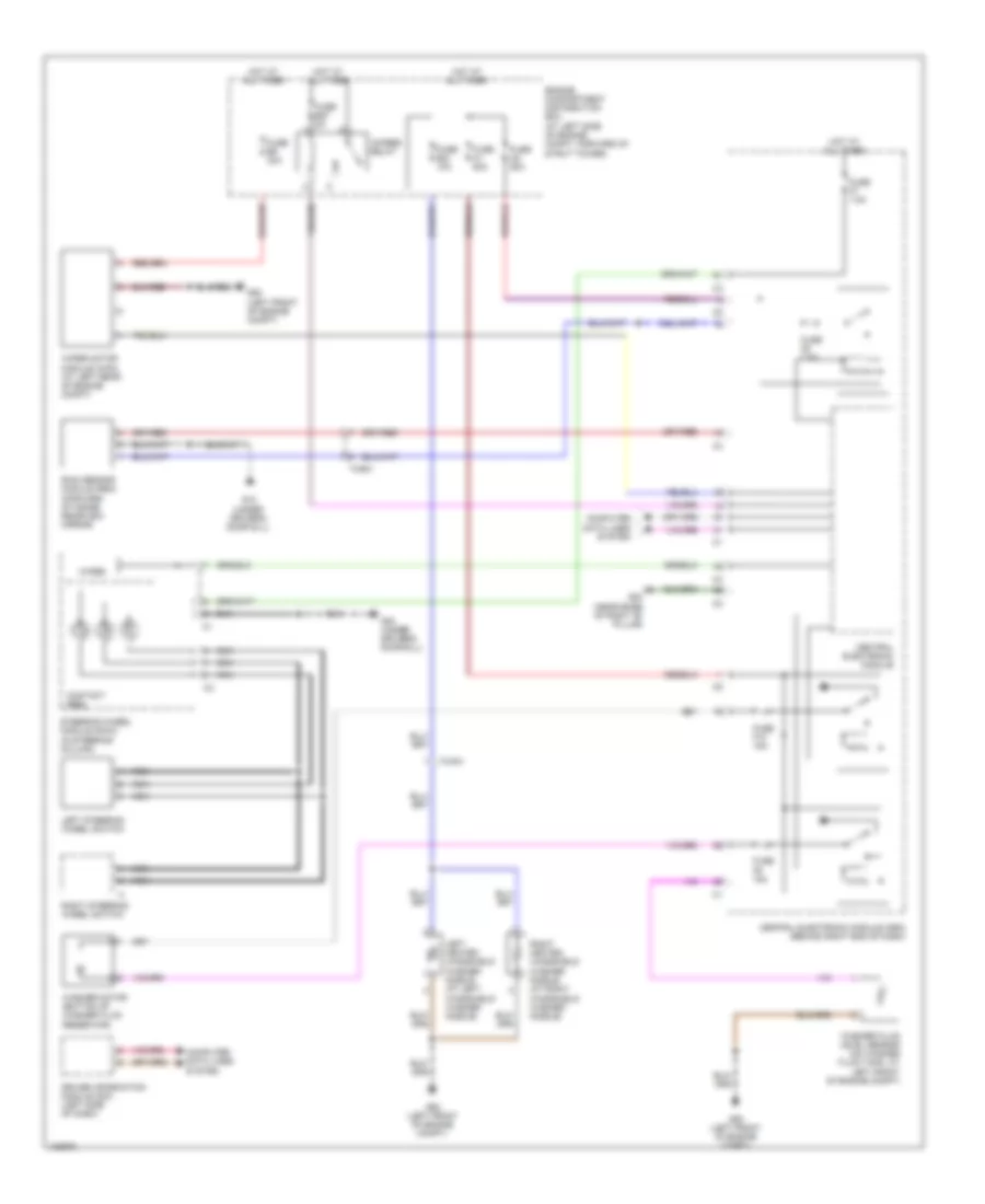
Instrument Illumination Wiring Diagram for Volvo S80 T6 2014
List of elements for Instrument Illumination Wiring Diagram for Volvo S80 T6 2014:
- 74/411
- 74/507
- 74/508
- 74/509
- 74/510
- Cem
- Central electronic module (behind right end of dash)
- Computer data lines system
- Driver door module (in driver's door)
- Driver's door central locking system switch
- Engine compartment distribution box (at left side of engine compt, forward of strut tower)
- Fuse b23 5a
- Fuse c10 20a
- Fuse c11 20a
- Fuse c8 20a
- Fuse c9 20a
- G15 (near base of right "b" pillar)
- G6 (near base of left "b" pillar)
- G83 (under driver's door sill)
- Gear selector module (center console)
- Hot at all times
- Left rear door module (in left rear door)
- Left rear door power window switch
- Light switch module
- Passenger compartment distribution box (right side of dash)
- Passenger door central locking system switch
- Passenger door module (in front passenger's door)
- Passenger door power window switch
- Red
- Right rear door module (in right rear door)
- Right rear door power window switch
- Steering wheel module (in steering column)
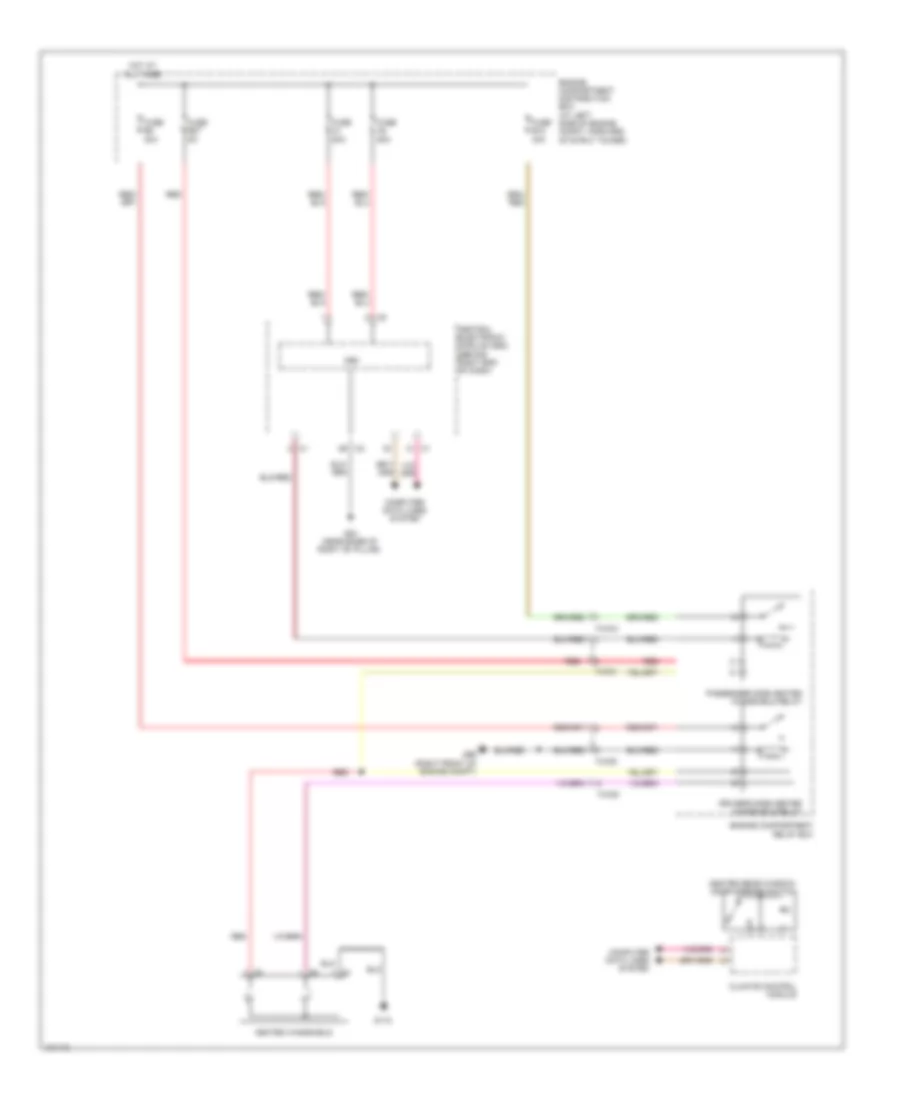
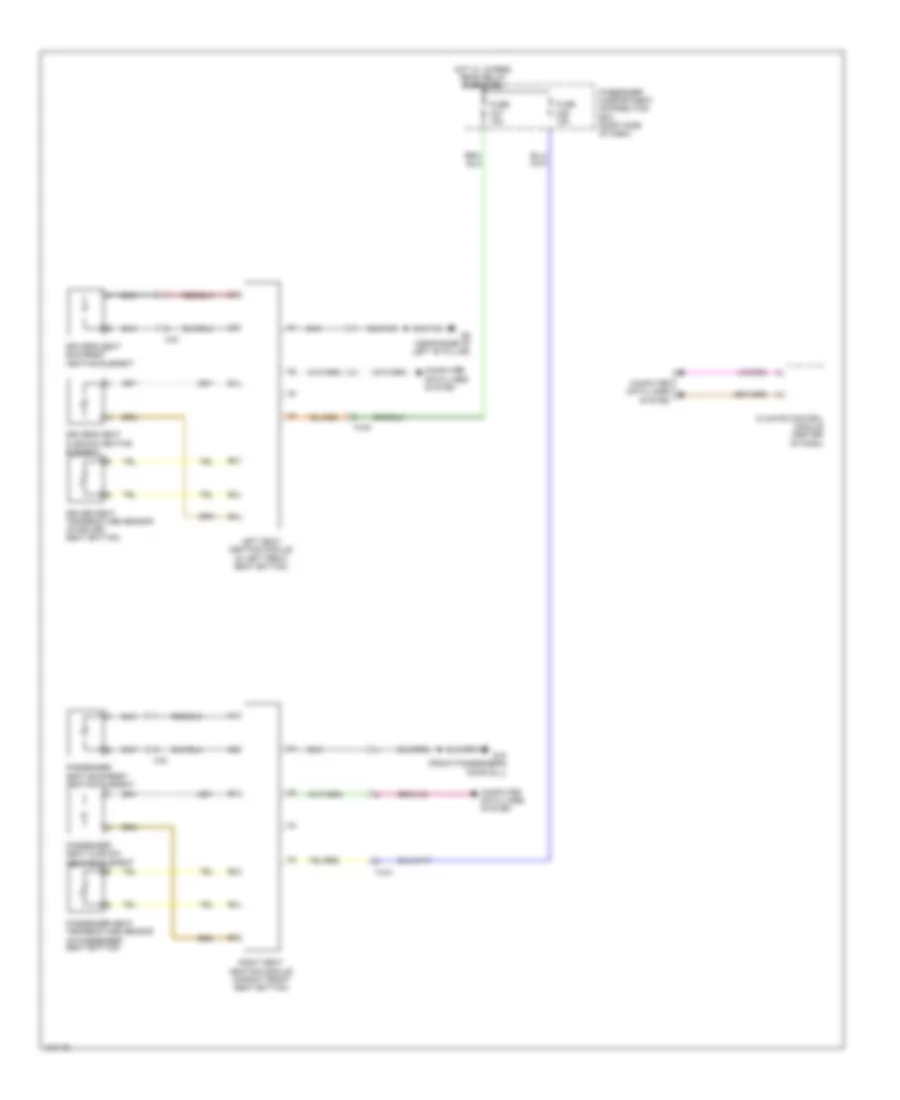
MEMORY SYSTEMS
Driver"s Memory Seat Wiring Diagram for Volvo S80 T6 2014
List of elements for Driver"s Memory Seat Wiring Diagram for Volvo S80 T6 2014:
- 30 p
- 31 p
- 31 s
- 74/30
- Can+
- Can-
- Computer data lines system
- Driver backrest angle seat motor (in driver's seat back)
- Driver forward/ backward seat motor (in driver seat)
- Driver up/down front edge seat motor (in driver's seat bottom)
- Driver up/down rear edge seat motor (in driver's seat bottom)
- Driver's power seat switch unit
- Engine compartment distribution box (at left side of engine compt, forward of strut tower)
- Extx
- Fuse a4 60a
- Fuse c13 20a
- G6 (near base of left "b" pillar)
- Hhf
- Hhr
- Hot at all times
- Interior lights system
- Lhf
- Lhr
- Passenger compartment distribution box (right side of dash)
- Power seat module (left side of driver's seat cushion)
- Red
- Rhf
- Rhr
- Thf
- Thr
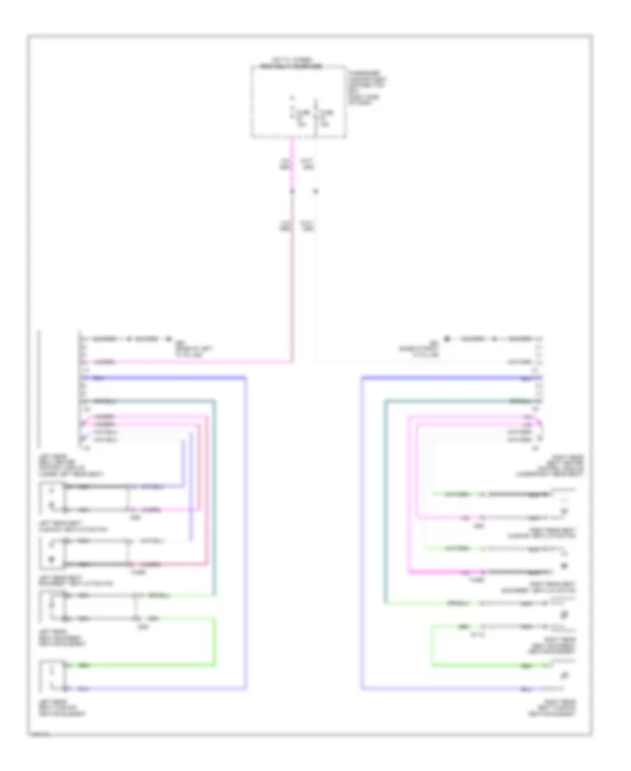
Memory Mirrors Wiring Diagram for Volvo S80 T6 2014
List of elements for Memory Mirrors Wiring Diagram for Volvo S80 T6 2014:
- (near base of left "b" pillar) g6
- 74/507
- 74/508
- Air conditioning system
- Computer data lines system
- Defogger system
- Driver's door module (ddm) (in driver's front door)
- Driver's door power window switch
- Exterior lights system
- Fuse c8 20a
- Fuse c9 20a
- G15 (near base of right 'b' pillar)
- Hot at all times
- Interior lights system
- Left camera module
- Left power door mirror (in driver's door mirror)
- Mem x
- Mem y
- Navigation system
- Outdoor temperature sensor
- Passenger compartment distribution box (right side of dash)
- Passenger's door module (pdm) (in passenger's front door)
- Red
- Right camera module
- Right power door mirror (in front passenger door mirror)
NAVIGATION
Blind Spot Information System Wiring Diagram for Volvo S80 T6 2014
List of elements for Blind Spot Information System Wiring Diagram for Volvo S80 T6 2014:
- (near base of right "b" pillar)
- 74/507
- 74/508
- Camera module
- Cem
- Central electronic module (behind right end of dash)
- Computer data lines system
- Driver's door module (in driver's front door)
- Driver's door power window switches
- Engine compartment distribution box (at left side of engine compartment, forward of strut tower)
- Fuse a2 50a
- Fuse a4 60a
- Fuse c8 20a
- Fuse c9 20a
- Fuse f3 7.5a
- G15
- G6 (near base of left "b" pillar)
- Hot at all times
- Left power door mirror (in driver's door mirror)
- Passenger compartment distribution box (right side of dash)
- Passenger's door module (in passenger's front door)
- Red
- Right power door mirror (in front passenger door mirror)
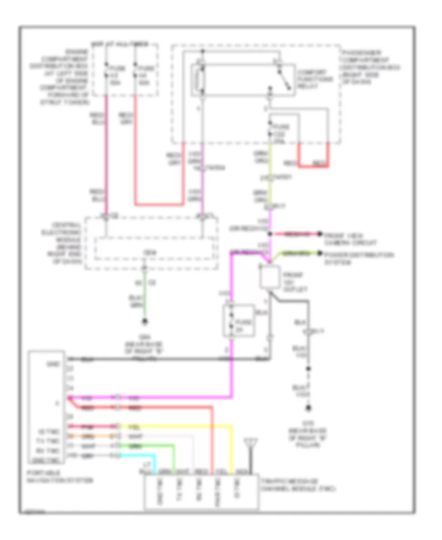
Front View Camera Wiring Diagram for Volvo S80 T6 2014
List of elements for Front View Camera Wiring Diagram for Volvo S80 T6 2014:
- (information not available)
- (near base of right "b" pillar) g84
- 74/409
- 74/501
- 74/504
- 9x/1
- Cem
- Central electronic module (behind right end of dash)
- Comfort functions relay
- Computer data lines system
- Engine compartment distribution box (at left side of engine compartment, forward of strut tower)
- Front 12v outlet
- Fuse 1a
- Fuse a2 50a
- Fuse a4 60a
- Fuse c1 40a
- Fuse c16 5a
- Fuse c22 15a
- G15 (near base of right "b" pillar)
- Hot at all times
- Infotainment control module (icm) (center of dash)
- Nca
- Passenger compartment distribution box (right side of dash)
- Power distribution system
- Red
- Sound systems
- Wide angle front camera
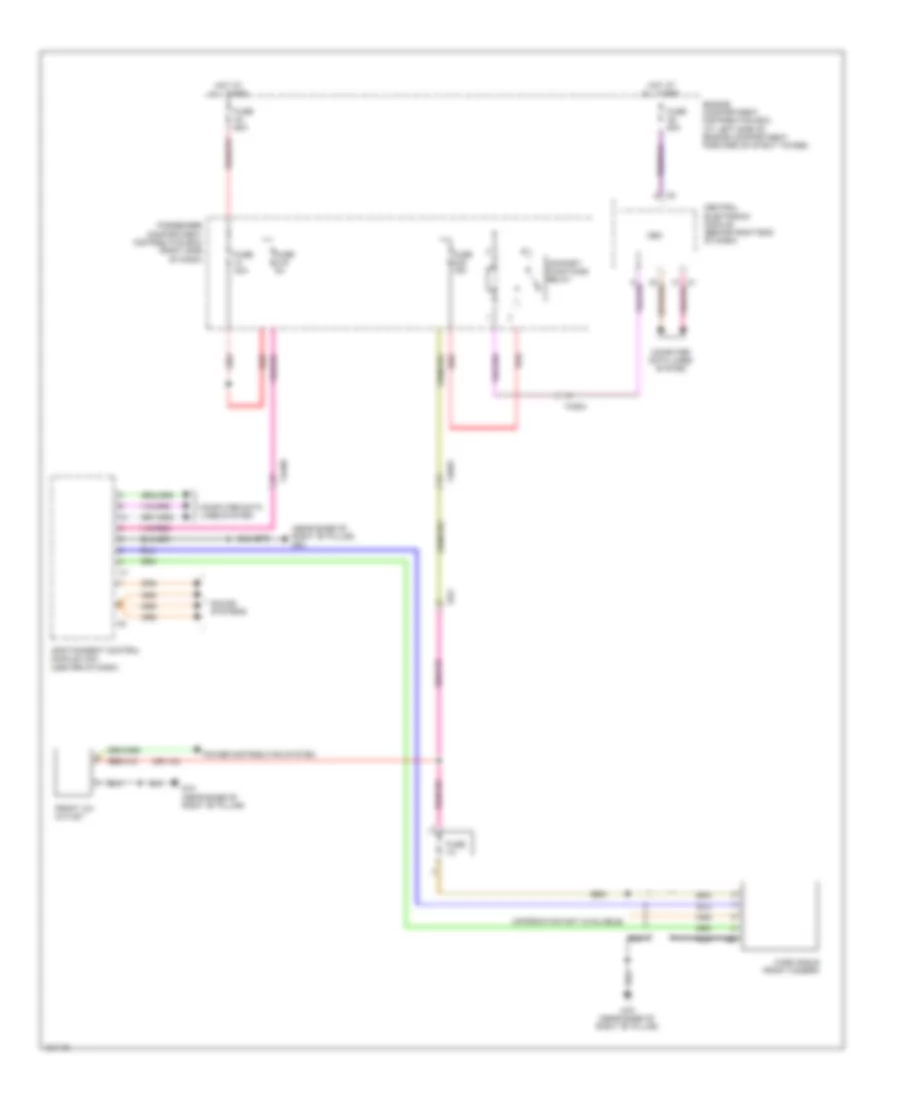
Navigation Wiring Diagram for Volvo S80 T6 2014
List of elements for Navigation Wiring Diagram for Volvo S80 T6 2014:
- 74/501
- 74/504
- 9x/1
- Cem
- Central electronic module (behind right end of dash)
- Comfort functions relay
- Engine compartment distribution box (at left side of engine compartment, forward of strut tower)
- Front 12v outlet
- Front view camera circuit
- Fuse 2a
- Fuse a2 50a
- Fuse a4 60a
- Fuse c22 15a
- G15 (near base of right "b" pillar)
- G84 (near base of right "b" pillar)
- Gnd
- Gnd tmc
- Hot at all times
- Id tmc
- Nca
- Passenger compartment distribution box (right side of dash)
- Pnk
- Portable navigation system
- Power distribution system
- Pwr tmc
- Red
- Rx tmc
- Traffic message channel module (tmc)
- Tx tmc
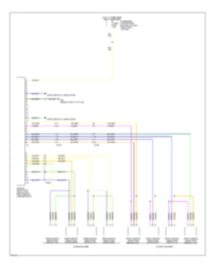
Parking Assistant Wiring Diagram for Volvo S80 T6 2014
List of elements for Parking Assistant Wiring Diagram for Volvo S80 T6 2014:
- (in front bumper)
- (in rear bumper)
- 74/309
- 74/519
- 74/523
- Computer data lines system
- Front parking assistance sensor (lf/i)
- Front parking assistance sensor (lf/o)
- Front parking assistance sensor (rf/i)
- Front parking assistance sensor (rf/o)
- Fuse c28 5a
- G67 (base of right "c" pillar)
- Hot w/ 15 feed rear relay energized
- Parking assistance module (pam) (right rear of luggage compt)
- Passenger compartment distribution box (right side of dash)
- Rear parking assistance sensor (lr/i)
- Rear parking assistance sensor (lr/o)
- Rear parking assistance sensor (rr/i)
- Rear parking assistance sensor (rr/o)
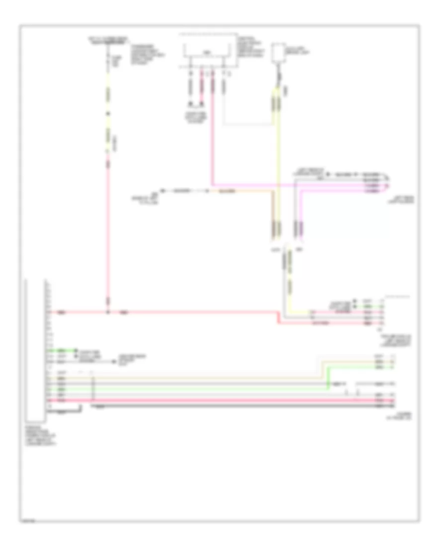
Rear Camera Wiring Diagram for Volvo S80 T6 2014
List of elements for Rear Camera Wiring Diagram for Volvo S80 T6 2014:
- (center rear of roof) g107
- (left rear of luggage compt) g47
- 4x/110c2
- 74/602
- Auxiliary brake light
- Camera (in trunk lid)
- Cem
- Central electronic module (behind right end of dash)
- Computer data lines system
- Fuse c28 15a
- G65 (base of left "c" pillar)
- Hot w/ 15 feed rear relay energized
- Left rear lamp housing
- Nca
- Parking assistance camera module (left rear of luggage compt)
- Passenger compartment distribution box (right side of dash)
- Pnk
- Red
- S80
- Trailer module (left rear of luggage compt)
- Xc70
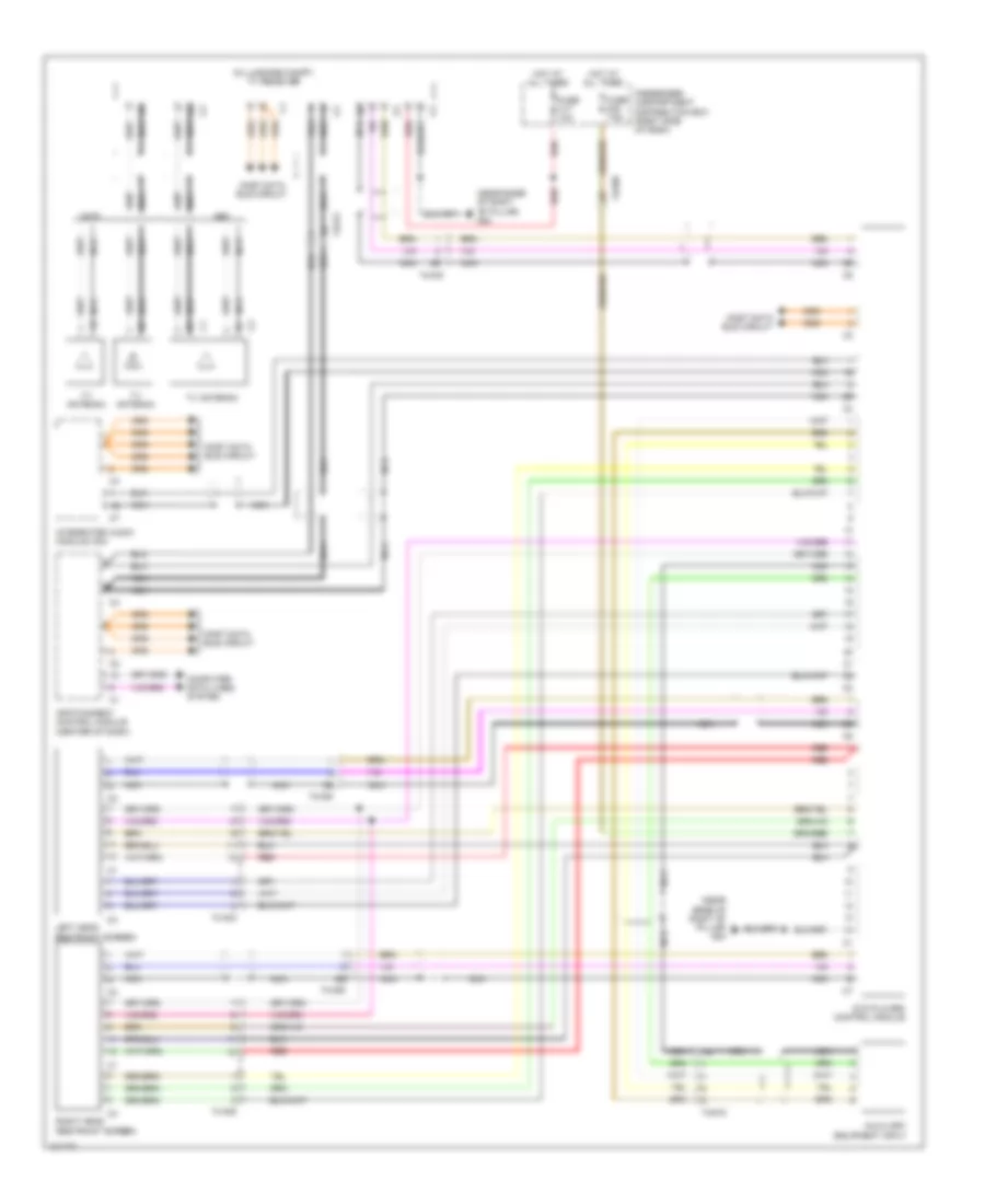
POWER DISTRIBUTION
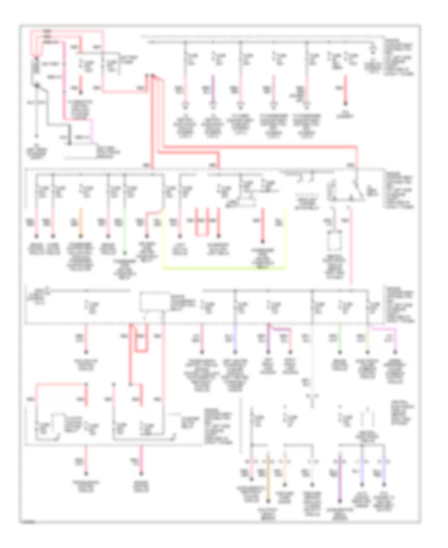
Power Distribution Wiring Diagram (1 of 3) for Volvo S80 T6 2014
List of elements for Power Distribution Wiring Diagram (1 of 3) for Volvo S80 T6 2014:
- Accelerator pedal sensor
- Accessory auxiliary light relay
- Alternator control module & starter motor
- Auto dimming rearview mirror
- Battery
- Battery fuses
- Battery monitoring sensor
- Brake control module
- Central electronic module
- Central electronic module (behind right end of dash)
- Climate control system relay
- Cooling fan control module
- Driver's side heated windshield relay
- Electronic power steering control module
- Engine compartment distribution box (at left side of engine compt, forward of strut tower)
- Engine control module
- Engine management system main relay
- Feed relay
- Forward aimed radar
- Forward sensing module & closing velocity module
- From a fuse a7 (diagram 1 of 3)
- Fuse a1 50a
- Fuse a2 50a
- Fuse a3 60a
- Fuse a4 60a
- Fuse a43 80a
- Fuse a5 60a
- Fuse a6 (not used)
- Fuse a7 100a
- Fuse b11 40a
- Fuse b12 40a
- Fuse b13 40a
- Fuse b14 20a
- Fuse b16 10a
- Fuse b17 20a
- Fuse b18 5a
- Fuse b19 5a
- Fuse b20 10a
- Fuse b21 10a
- Fuse b23 5a
- Fuse b27 5a
- Fuse b28 20a
- Fuse b29 15a
- Fuse b30 10a
- Fuse b31 15a
- Fuse b32 15a
- Fuse b34 30a
- Fuse b8 40a
- Fuse b9 30a
- Fuse f18 10a
- Fuse f19 5a
- Fuse f20 7.5a
- Fuse pf1 150a
- Fuse pf2 150a
- G3 (left rear of engine compt)
- Headlight washer motor relay
- Horn relay
- Left front lamp housing
- Left heated windshield washer nozzle & right heated windshield washer nozzle
- Light switch module
- Nca
- Occupant weight sensor
- Passenger compartment fan control module & passenger compartment fan motor
- Passenger side heated windshield relay
- Ptc element
- Ptc element & heated rear seat switch
- Red
- Right front lamp housing
- Speed dependent power steering control module
- Starter motor relay
- To cargo compartment fuse box (diagram 2 of 3)
- To central electronic module (diagram 2 of 3)
- To fuse a43 (diagram 1 of 3)
- To passenger compartment distribution box (diagram 3 of 3)
- Transmission control module
- Wiper motor module
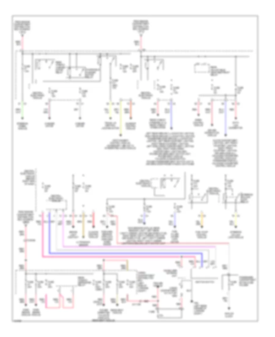
Power Distribution Wiring Diagram (2 of 3) for Volvo S80 T6 2014
List of elements for Power Distribution Wiring Diagram (2 of 3) for Volvo S80 T6 2014:
- 10a
- 4x/110b
- 74/504b
- Analog clock
- Brake light contact
- Cargo compartment 12v outlet (s80)
- Cargo compartment distribution box (left side of luggage compt)
- Central electronic module
- Central electronic module (behind right end of dash)
- Climate control module
- Data link connector
- Driver information module
- Forward sensing module & forward aimed radar
- From engine compartment distribution box (diagram 1 of 3)
- Fuel filler cover lock motor
- Fuel pump control module
- Fuse
- Fuse 5a
- Fuse a1 30a
- Fuse a11 40a
- Fuse a2 30a
- Fuse a3 30a
- Fuse a4 (not used)
- Fuse a5 30a
- Fuse a6 20a
- Fuse f1 15a
- Fuse f10 15a
- Fuse f11 (s80) 10a
- Fuse f13 20a
- Fuse f14 5a
- Fuse f15 15a
- Fuse f16 5a
- Fuse f21 15a
- Fuse f22 5a
- Fuse f23 20a
- Fuse f24 5a
- Fuse f3 7.5a
- Fuse f4 5a
- Fuse f5 10a
- Fuse f6 7.5a
- Fuse f7 7.5a
- Fuse f8 10a
- Fuse f9 15a
- Glove compartment lighting, left front courtesy lighting, right front courtesy lighting, driver's side sill moldings converter/ control module & passenger side sill moldings converter/ control module
- Ignition switch
- Immobilizer antenna unit
- Infotainment control module, accessory usb unit & integrated audio module
- Left rear ground illumination lighting, right rear ground illumination lighting, passenger side ground illumination lighting, left rear courtesy lighting, right rear courtesy lighting, left side cargo compartment lighting (s80), right side cargo compartment lighting (s80), power driver's seat switch unit, power seat module, tailgate closing switch, power passenger seat switch unit & driver's door power window switches
- Park brake module
- Passenger compartment extra fuse holder
- Power operated tailgate module & rear seat module
- Rain sensor module, rear reading light, left rear vanity mirror lighting (s80 executive), right rear vanity mirror lighting (s80 executive), left vanity mirror lighting, right vanity mirror lighting & ceiling light switch unit
- Rear adjustable head restraint relay
- Rear seat module
- Rear window defroster relay
- Rear window washer motor relay
- Rear window wiper relay & rear window wiper motor
- Red
- Siren control module
- Steering column lock module
- Steering column lock relay
- Steering wheel module
- Sunroof control module
- Trailer module
- Trm (left rear corner of luggage compt)
- Trunk lid central locking motor
- Ultrasonic sensor
- Washer motor
- Windshield washer motor relay
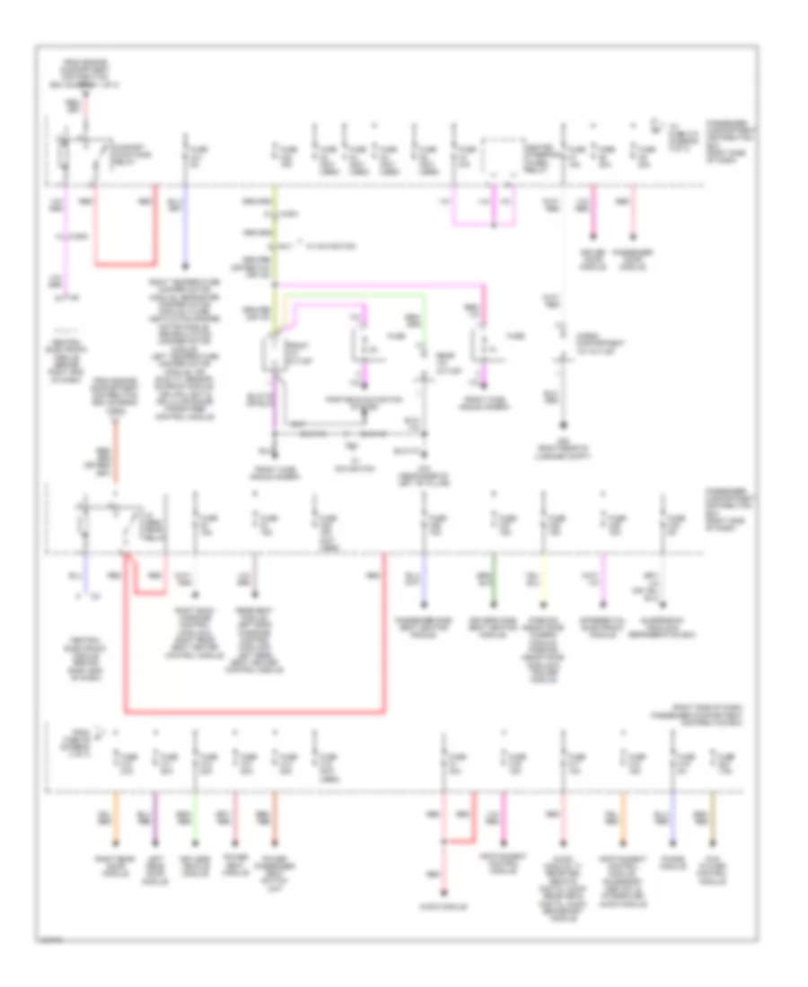
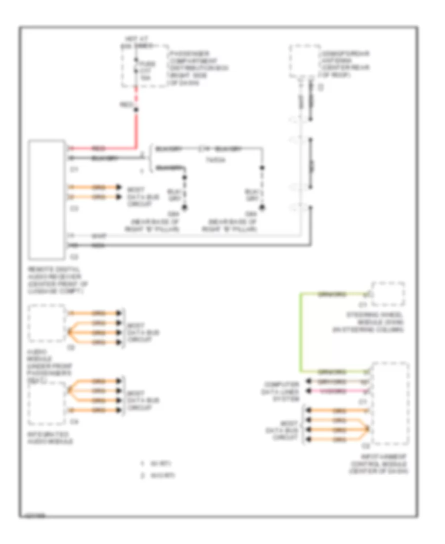
Power Distribution Wiring Diagram (3 of 3) for Volvo S80 T6 2014
List of elements for Power Distribution Wiring Diagram (3 of 3) for Volvo S80 T6 2014:
- (right side of dash) passenger compartment distribution box
- 74/501
- 74/504
- 9x/1
- Audio module
- Audio module, tv receiver, remote digital audio receiver & digital audio broadcast module
- Cargo compartment 12v outlet
- Central electronic module (behind right end of dash)
- Comfort functions relay
- Differential electronic module
- Driver door module
- Driver's side seat heating module,
- Dvd player control module
- Feed rear relay
- From engine compartment distribution box (diagram 1 of 3)
- From g fuse c9 (diagram 3 of 3)
- Front 12v outlet
- Front wide angle camera
- Fuse
- Fuse 15a
- Fuse c1 40a
- Fuse c10 20a
- Fuse c11 20a
- Fuse c12 20a
- Fuse c13 20a
- Fuse c14 20a
- Fuse c15 (not used)
- Fuse c16 15a
- Fuse c17 10a
- Fuse c18 15a
- Fuse c19 5a
- Fuse c2 (not used)
- Fuse c20 7.5a
- Fuse c21 5a
- Fuse c22 15a
- Fuse c25 15a (not used)
- Fuse c26 15a
- Fuse c27 15a
- Fuse c28 15a
- Fuse c29 15a
- Fuse c3 (not used)
- Fuse c30 5a
- Fuse c4 n/a
- Fuse c5 (not used)
- Fuse c6 (not used)
- Fuse c7 15a
- Fuse c8 20a
- Fuse c9 20a
- G15 (near base of left "b" pillar)
- G48 (right rear of luggage compt)
- Heated steering wheel relay
- Infotainment control module
- Infotainment control module, accessory usb unit & integrated audio module
- Keyless vehicle module
- Left rear door module
- Parking assistance camera module, parking assistance module & trailer module
- Passenger compartment distribution box (right side of dash)
- Passenger door module
- Passenger side seat heating module,
- Phone module
- Portable navigation system
- Power passenger seat switch unit
- Power seat module
- Rear 12v outlet
- Rear seat module, left back massage control module & left rear seat heater control module
- Red
- Right back massage control module & right rear seat heater control module
- Right rear door module
- Right temperature damper motor module, defroster damper motor module, floor/ ventilation damper motor module, recirculation damper motor module, left temperature damper motor module, air quality sensor, sunroof module, ceiling light & cellular phone hands free control module
- Suspension module & refrigeration box
- To fuse c10 (diagram 3 of 3)
- W/ navigation
POWER DOOR LOCKS
Power Door Locks Wiring Diagram, with Intelligent Key (1 of 2) for Volvo S80 T6 2014
List of elements for Power Door Locks Wiring Diagram, with Intelligent Key (1 of 2) for Volvo S80 T6 2014:
- (near base of right "b" pillar) g84
- (not used)
- (pins: 10 to 13 not used)
- (pins: 15 & 16 not used)
- (pins: 16 to 20 not used)
- (pins: 19 & 20 not used)
- (pins: 5 to 13 not used)
- (pins: 5 to 8 not used)
- (pins: 6 to 13 not used)
- (under driver's door sill) g10
- 74/507
- 74/508
- 74/509
- 74/510
- Antenna
- Central electronic module
- Central electronic module (behind right end of dash)
- Clutch
- Computer data lines system
- Engine compartment distribution box (at left side of engine compt, forward of strut tower)
- Front door lock unit (rear of right front door)
- Fuse a1 50a
- Fuse a2 50a
- Fuse c12 20a
- Fuse f22 5a
- G15 (near base of right "b" pillar)
- G48 (right rear of luggage compt)
- Gnd
- Hot at all times
- Keyless vehicle module (right side of luggage compt)
- Lock
- Passenger compartment distribution box (right side of dash)
- Pwr
- Release
- Remote keyless entry (rke) (center rear of roof)
- Right front door lock contact (in front passenger's door)
- Right rear door lock contact (in right rear door)
- Right unlock
- Right unlock rear door lock unit (right rear door)
- Sig
Power Door Locks Wiring Diagram, with Intelligent Key (2 of 2) for Volvo S80 T6 2014
List of elements for Power Door Locks Wiring Diagram, with Intelligent Key (2 of 2) for Volvo S80 T6 2014:
- (not used)
- 74/501
- 74/507
- 74/509
- 74/601
- 74/602
- 74/603
- Antenna
- Brake light contact (top of brake pedal assembly)
- Bumper door lock antenna (s80) (under center of rear bumper)
- Cargo compartment door lock antenna (in cargo compt)
- Clutch
- Exterior light system
- Exterior lights system
- Front door lock unit (rear of left front door)
- G47 (left rear of luggage compt)
- G6 (near base of left "b" pillar)
- G65 (base of left "c" pillar)
- Left front door lock contact (in driver's door)
- Left rear door lock contact (in left rear door)
- Left unlock
- License plate lighting
- Lock
- Passenger compartment 2 door lock antenna (under driver seat)
- Passenger compartment 3 door lock antenna (under center of dash)
- Power operated tailgate module
- Rear door lock unit (left rear door)
- Release
- S80
- Trunk handle switch (s80)
- Trunk handle switch (xc70)
- Trunk lid/ tailgate door lock antenna (xc70)
- Xc70
Power Door Locks Wiring Diagram, without Intelligent Key (1 of 2) for Volvo S80 T6 2014
List of elements for Power Door Locks Wiring Diagram, without Intelligent Key (1 of 2) for Volvo S80 T6 2014:
- (not used)
- 74/412
- 74/507
- 74/508
- Ajar
- Central electronic module
- Central electronic module (behind right end of dash)
- Computer data lines system
- Driver door module (in driver front door)
- Driver's door central locking switch
- Engine compartment distribution box (at left side of engine compt, forward of strut tower)
- Front door central locking lock motor (rear of right front door)
- Fuel filler cover lock motor (right side of luggage compt)
- Fuse a1 50a
- Fuse a2 50a
- Fuse f11 (s80) 10a
- Fuse f8 10a
- G10 (under driver's door sill)
- G15 (near base of right "b" pillar)
- G48 (right rear of luggage compt)
- G6 (near base of left "b" pillar)
- G84 (near base of right "b" pillar)
- Ground
- Hot at all times
- Left front door central locking lock motor (rear of left front door)
- Light switch module
- Lock
- Lock central
- Lock double
- Locking common
- Passenger door module (in passenger front door)
- Passenger door power window switch
- Passenger's door central locking switch
- Red
- Remote receiver module (rrx)
- Right locking common
- Switch lock
- Trunk lid/tailgate private lock switch
- Un- lock
Power Door Locks Wiring Diagram, without Intelligent Key (2 of 2) for Volvo S80 T6 2014
List of elements for Power Door Locks Wiring Diagram, without Intelligent Key (2 of 2) for Volvo S80 T6 2014:
- (left rear of luggage compt) g47
- (xc70) tailgate closing motor
- 74/509
- 74/510
- 74/601
- 74/602
- 74/603
- Ajar
- Central electronic module
- Central electronic module (behind right end of dash)
- Child
- Child lock
- Computer data lines system
- Exterior lights system
- Fuse c10 20a
- Fuse c11 20a
- Fuse c8 20a
- Fuse c9 20a
- G15 (near base of right "b" pillar)
- G6 (near base of left "b" pillar)
- G65 (base of left "c" pillar)
- Ground
- Hot at all times
- Interior lights system
- Left lock
- Left rear door module (in left rear door)
- Lock central
- Lock double
- Locking common
- Passenger compartment distribution box (right side of dash)
- Power operated tailgate module
- Rear door central locking lock motor (left rear door)
- Rear door central locking lock motor (right rear door)
- Red
- Right lock
- Right rear door module (in right rear door)
- Trunk handle switch (s80)
- Trunk lid central locking motor (s80) (center rear of trunk lid)
- Trunk lid central locking motor (xc70) (center rear of trunk lid)
- Trunk, tailgate, fuel doors system
POWER MIRRORS
Power Mirrors Wiring Diagram for Volvo S80 T6 2014
List of elements for Power Mirrors Wiring Diagram for Volvo S80 T6 2014:
- Auto dimming rearview mirror
- Central electronic module (cem) (behind right end of dash)
- Computer data lines system
- Fuse f20 7.5a
- G10 (under driver's door sill)
- Hot w/ 15-feed relay energized
- Moisture sensor
POWER SEATS
Front Heated Seats Wiring Diagram, with Fans for Volvo S80 T6 2014
List of elements for Front Heated Seats Wiring Diagram, with Fans for Volvo S80 T6 2014:
- 74/30
- 74/31
- C28
- C29
- C42
- C44
- C45
- Climate control module (center of dash)
- Computer data lines system
- Driver's seat backrest heating element
- Driver's seat cushion heating element
- Driver's seat temperature sensor (in driver's front seat bottom)
- Fuse c26 15a
- Fuse c27 15a
- G15 (near base of right "b" pillar)
- G6 (near base of left "b" pillar)
- Hot w/ 15-feed rear relay energized
- Left seat heating module (in left front seat bottom)
- Nca
- Passenger compartment distribution box (right side of dash)
- Passenger seat backrest heating element
- Passenger seat cushion heating element
- Passenger seat heating module (in right front seat bottom)
- Passenger seat temperature sensor (in passenger's front seat bottom)
- Seat fan
Front Heated Seats Wiring Diagram, without Fans for Volvo S80 T6 2014
List of elements for Front Heated Seats Wiring Diagram, without Fans for Volvo S80 T6 2014:
- 74/30
- 74/31
- C42
- Climate control module (center of dash)
- Computer data lines system
- Driver seat temperature sensor (in driver seat bottom)
- Driver's seat backrest heating element
- Driver's seat cushion heating element
- Fuse c26 15a
- Fuse c27 15a
- G15 (front passenger's door sill)
- G6 (near base of left "b" pillar)
- Hot w/ 15-feed rear relay energized
- Left seat heating module (in left front seat bottom)
- Passenger compartment distribution box (right side of dash)
- Passenger seat backrest heating element
- Passenger seat cushion heating element
- Passenger seat temperature sensor (in passenger seat bottom)
- Right seat heating module (in right front seat bottom)
Heated Steering Wheel Wiring Diagram for Volvo S80 T6 2014
List of elements for Heated Steering Wheel Wiring Diagram for Volvo S80 T6 2014:
- C74/409
- Cem
- Central electronic module (behind right end of dash)
- Computer data lines system
- Engine compartment distribution box (at left side of engine compt, forward of strut tower)
- Fuse a1 50a
- Fuse a2 50a
- Fuse a4 60a
- Fuse c4 n/a
- G83 (under driver's door sill)
- G84 (near base of right "b" pillar)
- Heated steering wheel control module
- Heated steering wheel relay
- Heated steering wheel temperature sensor
- Hot at all times
- Nca
- Passenger compartment distribution box (right side of dash)
- Steering wheel module (in steering column)
Massage Seat Wiring Diagram (1 of 2) for Volvo S80 T6 2014
List of elements for Massage Seat Wiring Diagram (1 of 2) for Volvo S80 T6 2014:
- 22/6
- 74/409
- Cargo compartment distribution box (left side of luggage compt)
- Cem
- Central electronic module (behind right end of dash)
- Computer data lines system
- Engine compartment distribution box (at left side of engine compt, forward of strut tower)
- Fuse a1 50a
- Fuse a2 50a
- Fuse a5 30a
- Fuse a6 20a
- G-trm (left rear corner of luggage compt)
- G84 (near base of right "b" pillar)
- Hot at all times
- Left rear seat adjustment switch
- Left rear seat backrest reclining motor
- Nca
- Overhead console lightning
- Rear seat module
- Right rear seat adjustment switch
- Right rear seat backrest reclining motor
- Sun curtain motor
- Sun curtain rear switch
Massage Seat Wiring Diagram (2 of 2) for Volvo S80 T6 2014
List of elements for Massage Seat Wiring Diagram (2 of 2) for Volvo S80 T6 2014:
- (left rear corner of luggage compt)
- 9/11c
- 9/9c
- Fuse 15a
- G-trm
- G-trm (left rear corner of luggage compt)
- Hot w/ 15-feed rear relay energized
- Left back massage control module (in driver's seat back)
- Left back massage pump (left rear of luggage compt)
- Left rear seat massage & ventilation switch
- Nca
- Passenger compartment distribution box (right side of dash)
- Rear heated seat switch
- Right back massage control module (in front passenger's seat back)
- Right back massage pump (left rear of luggage compt)
- Right rear seat massage & ventilation switch
Passenger"s Power Seat Wiring Diagram for Volvo S80 T6 2014
List of elements for Passenger"s Power Seat Wiring Diagram for Volvo S80 T6 2014:
- 74/31
- Back
- Backrest switch
- Down
- Engine compartment distribution box (at left side of engine compartment, forward of of strut tower)
- Forw
- Forward/ backward switch
- Front edge up/down switch
- Fuse a4 60a
- Fuse c14 20a
- G15 (near base of right "b" pillar)
- Hot at all times
- Interior lights system
- Passenger backrest angle seat motor (in passenger seat back)
- Passenger compartment distribution box (right side of dash)
- Passenger forward/ backward seat motor (in front passenger seat)
- Passenger up/down front edge seat motor
- Passenger up/down rear edge motor
- Power passenger seat switch unit
- Rear edge up/down switch
- Red
- Stop logic
Rear Head Restraint Wiring Diagram for Volvo S80 T6 2014
List of elements for Rear Head Restraint Wiring Diagram for Volvo S80 T6 2014:
- Cem
- Central electronic module (cem) (behind right end of dash)
- Climate control module (center of dash)
- Computer data lines system
- Engine compartment distribution box (at left end of engine compartment, forward of strut tower)
- Fuse a2 50a
- Fuse f12 10a
- G65 (base of left "c" pillar)
- G67 (base of right "c" pillar)
- G84 (near base of right "b" pillar)
- Hot at all times
- Left rear folding head restraint motor (in left rear head restraint)
- Left rear headrest restraint solenoid (in left rear seat headrest)
- Nca
- Rear adjustable head restraint relay
- Rear adjustable head restraint switch
- Right rear folding head restraint motor (in right rear head restraint)
- Right rear headrest restraint solenoid (in right rear seat headrest)
Rear Heated Seats Wiring Diagram, with Massage for Volvo S80 T6 2014
List of elements for Rear Heated Seats Wiring Diagram, with Massage for Volvo S80 T6 2014:
- 74/560
- 9/11c
- 9/9c
- Fuse 15a
- G65 (base of left "c" pillar)
- G67 (base of right "c" pillar)
- Hot w/ 15-feed rear relay energized
- Left rear seat backrest heating element
- Left rear seat backrest ventilation fan
- Left rear seat cushion heating element
- Left rear seat cushion ventilation fan
- Left rear seat heater control module (under left rear seat)
- Nca
- Passenger compartment distribution box (right side of dash)
- Right rear seat backrest heating element
- Right rear seat backrest ventilation fan
- Right rear seat cushion heating element
- Right rear seat cushion ventilation fan
- Right rear seat heater control module (under right rear seat)
Rear Heated Seats Wiring Diagram, without Massage for Volvo S80 T6 2014
List of elements for Rear Heated Seats Wiring Diagram, without Massage for Volvo S80 T6 2014:
- 74/403
- Central electronic module (cem) (behind right end of dash)
- Computer data lines system
- Engine compartment distribution box (at left side of engine compartment, forward of strut tower)
- Fuse b17 20a
- Fuse c23 15a
- Fuse c24 15a
- Fuse f20 7.5a
- G15 (near base of right "b" pillar)
- G65 (base of left "c" pillar)
- G67 (base of right "c" pillar)
- Hot w/ 15-feed rear relay energized
- Hot w/ 15-feed relay energized
- Left rear seat backrest heating element
- Left rear seat cushion heating element
- Left rear seat heater control module (under left rear seat)
- Left rear seat temperature sensor (in left rear seat bottom)
- Passenger compartment distribution box (right side of dash)
- Rear heated seats switch
- Right rear seat backrest heating element
- Right rear seat cushion heating element
- Right rear seat heater control module (under right rear seat)
- Right rear seat temperature sensor (in right rear seat bottom)
POWER TOP/SUNROOF
Power Top/Sunroof Wiring Diagram for Volvo S80 T6 2014
List of elements for Power Top/Sunroof Wiring Diagram for Volvo S80 T6 2014:
- 74/414
- 74/504
- Bwd gnd
- Ceiling light
- Cem
- Central electronic module (cem) (behind right end of dash)
- Comfort functions relay
- Engine compartment distribution box (at left side of engine compt, forward of strut tower)
- Fuse a4 60a
- Fuse c21 5a
- Fuse f23 20a
- Fwd
- G10 (under driver's door sill)
- Hot at all times
- Passenger compartment distribution box (right side of dash)
- Power sunroof switch
- Red
- Sunroof control module (srm) (forward of sunroof opening)
- Tilt
- Vbat global close
- Vspeed acc/comf feed
POWER WINDOWS
Power Windows Wiring Diagram for Volvo S80 T6 2014
List of elements for Power Windows Wiring Diagram for Volvo S80 T6 2014:
- 74/507
- 74/508
- 74/509
- 74/510
- Central electronic module
- Central electronic module (behind right end of dash)
- Computer data lines system
- Driver door module (ddm) (in driver front door)
- Driver's door power window switch
- Fuse c10 20a
- Fuse c11 20a
- Fuse c8 20a
- Fuse c9 20a
- Fuse f3 7.5a
- G15 (near base of right "b" pillar)
- G6 (near base of left "b" pillar)
- Hot at all times
- Interior lights system
- Left front power window motor (in left front door)
- Left rear door module (ldm) (in left rear door)
- Left rear door power window switch
- Left rear power window motor (in left rear door)
- Passenger compartment distribution box (right side of dash)
- Passenger door module (pdm) (in passenger front door)
- Passenger door power window switch
- Red
- Right front power window motor (in right front door)
- Right rear door module (rdm) (in right rear door)
- Right rear door power window switch
- Right rear power window motor (in right rear door)
RADIO
Digital Radio Wiring Diagram for Volvo S80 T6 2014
List of elements for Digital Radio Wiring Diagram for Volvo S80 T6 2014:
- 74/531
- 74/532
- Audio module (under front passenger's seat)
- Computer data lines system
- Digital audio broadcast module (dabm) (behind center of rear seat)
- Fuse c17 10a
- G84 (near base of right "b" pillar)
- Gsm/gps/rdar antenna (center rear of roof)
- Hot at all times
- Infotainment control module (center of dash)
- Integrated audio module
- Most data bus circuit
- Nca
- Passenger compartment distribution box (right side of dash)
- Red
- Steering wheel module (swm) (in steering column)
- W/ rti
- Window antenna amplifier 1 (at left "c" pillar)
MOST Data Bus Wiring Diagram for Volvo S80 T6 2014
List of elements for MOST Data Bus Wiring Diagram for Volvo S80 T6 2014:
- 16/145a
- 74/404
- Audio module (aud) (under front passenger's seat)
- Digital audio broadcast module (dabm) (behind center of rear seat)
- Dvd player/ control module
- Infotainment control module (center of dash)
- Integrated audio module (iam)
- Phone module (phm) (right side of dash)
- Remote digital audio receiver (rdar) (center front of luggage compt)
- Tv receiver (in luggage compt)
Radio Wiring Diagram, Base (1 of 2) for Volvo S80 T6 2014
List of elements for Radio Wiring Diagram, Base (1 of 2) for Volvo S80 T6 2014:
- (not used)
- 16x/1c1
- 3x/281c1
- 74/403
- 74/405
- 74/407
- 74/409
- 74/412
- 74/507
- 74/508
- 74/509
- 74/510
- Antenna pwr
- Aux 2 b +
- Aux 2 b -
- Aux 2 l +
- Aux 2 l -
- Aux l +
- Aux r +
- Aux r -
- Auxiliary equipment input
- Fuse c16 5a
- Fuse c18 15a
- G84 (near base of right "b" pillar)
- Hot at all times
- Integrated audio module
- Lf+
- Lf-
- Lr+
- Lr-
- Lvds+
- Lvds-
- Mic +
- Mic -
- Microphone (in overhead console)
- Most data bus circuit
- Nca
- Passenger compartment distribution box (right side of dash)
- Pwr gnd
- Rear seat entertainment circuit
- Rf+
- Rf-
- Rr+
- Rr-
- Shield
- Steering wheel module (swm) (in steering column)
- Vbatt
- W/ sensus connected touch
- W/o sensus connected touch
- Window antenna amplifier (at left "c" pillar)
- Window antenna amplifier 1
Radio Wiring Diagram, Base (2 of 2) for Volvo S80 T6 2014
List of elements for Radio Wiring Diagram, Base (2 of 2) for Volvo S80 T6 2014:
- (near base of right "b" pillar) g84
- (not used)
- 3x/281c1
- Accessory connectivity unit (acu) (w/ sensus connected touch)
- Aux 2 l+
- Aux 2 l-
- Aux 2 r+
- Aux 2 r-
- Computer data lines system
- Data+
- Data-
- Gnd
- Gps ant+
- Gps ant-
- Gps antenna
- Infotainment control module (center of dash)
- Left front door speaker
- Left front tweeter
- Left rear door speaker
- Lin
- Lvds+
- Lvds-
- Mic scr
- Mic sig
- Microphone (in overhead console)
- Most data bus circuit
- Nca
- Rear seat entertainment circuit
- Red
- Right front door speaker
- Right front tweeter
- Right rear door speaker
- Shield
- Usb-port
- Vbus
- W/ sensus connected touch
- W/o sensus connected touch
Radio Wiring Diagram, Premium (1 of 3) for Volvo S80 T6 2014
List of elements for Radio Wiring Diagram, Premium (1 of 3) for Volvo S80 T6 2014:
- (in overhead console) microphone
- 16/77b
- 16/77d
- 74/407
- 74/407b
- 74/409
- 74/507
- 74/508
- 74/509
- 74/510
- 74/534
- 74/562
- Audio module (under front passenger's seat)
- Center dashboard speaker
- Central electronics module (cem) (behind right end of dash)
- Computer data lines system
- Cs+
- Cs-
- Fuse c1 40a
- Fuse c17 10a
- Fuse f21 15a
- G-infot (right rear corner of luggage compt)
- Hot at all times
- Left front door speaker
- Left front mid-range loud speaker
- Left front tweeter
- Left rear door speaker
- Left rear door tweeter
- Lf+
- Lf-
- Lr+
- Lr-
- Most data bus circuit
- Nca
- Passenger compartment distribution box (right side of dash)
- Red
- Rf+
- Rf-
- Right front door speaker
- Right front mid-range loud speaker
- Right front tweeter
- Right rear door speaker
- Right rear door tweeter
- Rr+
- Rr-
- Sub woofer (+)
- Sub woofer (-)
- Sub woofer module
Radio Wiring Diagram, Premium (2 of 3) for Volvo S80 T6 2014
List of elements for Radio Wiring Diagram, Premium (2 of 3) for Volvo S80 T6 2014:
- (info not available)
- (near base of right "b" pillar) g84
- (not used)
- (not used) 3x/281c1
- (w/ accessory)
- 3x/281c1
- 74/401
- Accessory connectivity unit (acu) (w/ sensus connected touch)
- Accessory usb unit (auu) (behind left side of dash)
- Aux 2 l+
- Aux 2 l-
- Aux 2 r+
- Aux 2 r-
- Computer data
- Data+
- Data-
- G83 (under driver's door sill)
- Gnd
- Gps ant+
- Gps ant-
- Gps antenna
- Infotainment control module (center of dash)
- Lin
- Lines system
- Lvds+
- Lvds-
- Mic scr
- Mic sig
- Microphone (in overhead console)
- Most data bus circuit
- Nca
- Nca 1s
- Rear seat entertainment circuit
- Red
- Shield
- Usb port
- Vbus
- W/ sensus connected touch
- W/o sensus connected touch
Radio Wiring Diagram, Premium (3 of 3) for Volvo S80 T6 2014
List of elements for Radio Wiring Diagram, Premium (3 of 3) for Volvo S80 T6 2014:
- (in steering column)
- (not
- 16x/1c1
- 1s c1
- 1s nca
- 2s nca
- 3s nca
- 3x/281c1
- 74/403
- 74/405
- 74/409
- 74/412
- 74/419
- 74/420
- 74x/401
- Ant pwr
- Antenna
- Aux 2 b +
- Aux 2 b -
- Aux 2 l +
- Aux 2 l -
- Aux l +
- Aux r +
- Aux r -
- Auxiliary equipment input
- Circuit
- Data bus
- Data+
- Data-
- Fuse c16 5a
- Fuse c18 15a
- G84 (near base of right "b" pillar)
- Gnd
- Gsm/gps/rdar antenna (center rear of roof)
- Hot at all times
- Integrated audio module
- Lvds+
- Lvds-
- Mic +
- Mic -
- Microphone (in overhead console)
- Module (swm)
- Most
- Nca
- Passenger compartment distribution box (right side of dash)
- Pwr gnd
- Rear seat entertainment circuit
- Red
- Shield
- Steering wheel
- Usb-port (w/o accessory)
- Used)
- V bus
- Vbatt
- W/ sensus connected touch
- W/o sensus connected touch
- Window antenna amplifier (at left "c" pillar)
Rear Seat Entertainment Wiring Diagram for Volvo S80 T6 2014
List of elements for Rear Seat Entertainment Wiring Diagram for Volvo S80 T6 2014:
- (in luggage compt) tv receiver
- (near base of right "b" pillar) g84
- 74/409
- 74/421
- 74/428
- 74/429
- 74/430
- 74/515
- 74/543
- 74/545
- Auxiliary
- Computer data lines system
- Dvd player/ control module
- Equipment input
- Fuse c17 10a
- Fuse c20 7.5a
- Hot at all times
- Infotainment control module (center of dash)
- Integrated audio module (iam)
- Left head restraint screen
- Most data bus circuit
- Nca
- Passenger compartment distribution box (right side of dash)
- Red
- Right head restraint screen
- S80
- Tv antenna
- Xc70
Satellite Radio Wiring Diagram for Volvo S80 T6 2014
List of elements for Satellite Radio Wiring Diagram for Volvo S80 T6 2014:
- (near base of right "b" pillar)
- 74/534
- Audio module (under front passenger's seat)
- Computer data lines system
- Fuse c17 10a
- G84
- Gsm/gps/rdar antenna (center rear of roof)
- Hot at all times
- Infotainment control module (center of dash)
- Integrated audio module
- Most data bus circuit
- Nca
- Passenger compartment distribution box (right side of dash)
- Red
- Remote digital audio receiver (center front of luggage compt)
- Steering wheel module (swm) (in steering column)
- W/ rti
- W/o rti
TV Receiver Wiring Diagram for Volvo S80 T6 2014
List of elements for TV Receiver Wiring Diagram for Volvo S80 T6 2014:
- (near base of right "b" pillar) g84
- 74/421
- Computer data lines system
- Fuse c17 10a
- Hot at all times
- Infotainment control module (center of dash)
- Most data bus circuit
- Nca
- Passenger compartment distribution box (right side of dash)
- Rear seat entertainment circuit
- Red
- S80
- Tv antenna
- Tv receiver (in luggage compt)
- W/ tv
- Xc70
SHIFT INTERLOCK
Park Brake Release Wiring Diagram for Volvo S80 T6 2014
List of elements for Park Brake Release Wiring Diagram for Volvo S80 T6 2014:
- (under driver's door sill) g83
- 74/409
- 74/514
- 74/524
- Cargo compartment distribution box (left side of luggage compt)
- Cem
- Central electronic module (behind right end of dash)
- Computer data lines system
- Fuse a1 30a
- Fuse a2 30a
- G47 (left rear of luggage compt)
- Hot at all times
- Left rear brake disc lock motor (at left rear brake assembly)
- Parking brake module (pbm) (left side of trunk/cargo area)
- Parking brake switch
- Right rear brake disc lock motor (at right rear brake assembly)
Shift Interlock Wiring Diagram for Volvo S80 T6 2014
List of elements for Shift Interlock Wiring Diagram for Volvo S80 T6 2014:
- 15-feed relay
- 74/301
- 74/403
- 74/411
- B13
- B15
- B41
- B54
- Brake light contact (top of brake pedal assembly)
- Cem
- Central electronic module (behind right end of dash)
- Computer data lines system
- Electric transmission oil pump
- Engine compartment distribution box (at left side of engine compt, forward of strut tower)
- Engine control module (left rear of engine compt)
- Fuse a1 50a
- Fuse a2 50a
- Fuse b20 10a
- Fuse b27 5a
- Fuse b31 15a
- Fuse b40 20a
- Fuse f22 5a
- G15 (near base of right "b" pillar)
- Gear selector module (center console)
- Gxx10 (left front of engine compt)
- Hot at all times
- Hot w/ engine management system main relay energized
- Keyless vehicle module (kvm) (right side of luggage compt)
- Nca
- Shift lock solenoid (at base of gear selector lever)
- Steering wheel module (swm) (in steering column)
- Transmission control module (on transmission)
STARTING/CHARGING
Charging Wiring Diagram for Volvo S80 T6 2014
List of elements for Charging Wiring Diagram for Volvo S80 T6 2014:
- (left rear of engine compt) g3
- A92
- Alternator control module
- B41
- B54
- Battery
- Battery fuses
- Battery monitoring sensor (on battery)
- Central electronic module
- Central electronic module (behind right end of dash)
- Computer data lines system
- Driver information module (dim) (left side of dash)
- Engine control module (left rear of engine compt)
- Fuse pf2 150a
- Nca
- Red
- Starter motor
- Starting circuit
Starting Wiring Diagram (1 of 2) for Volvo S80 T6 2014
List of elements for Starting Wiring Diagram (1 of 2) for Volvo S80 T6 2014:
- (left rear of engine compt)
- 15-feed relay
- Alternator control module
- Battery
- Battery fuses
- Battery monitoring sensor (on battery)
- Charging circuit
- Engine compartment distribution box (at left side of engine compt, forward of strut tower)
- Fuse a1 50a
- Fuse a2 50a
- Fuse b17 20a
- Fuse b20 10a
- Fuse b27 5a
- Fuse b34 30a
- Fuse pf1 150a
- Fuse pf2 150a
- Nca
- Red
- Starter motor
- Starter motor relay
Starting Wiring Diagram (2 of 2) for Volvo S80 T6 2014
List of elements for Starting Wiring Diagram (2 of 2) for Volvo S80 T6 2014:
- 74/301
- B11
- B14
- B15
- B17
- B30
- B41
- B54
- Central electronic module
- Central electronic module (behind right end of dash)
- Computer data lines system
- Engine control module (left rear of engine compt)
- Fuse f15 15a
- Fuse f24 5a
- G10 (under driver's door sill)
- G83 (under driver's door sill)
- Ignition switch
- Immobilizer antenna unit
- Steering column lock module (on steering column)
- Steering column lock relay
SUPPLEMENTAL RESTRAINTS
Supplemental Restraints Wiring Diagram (1 of 3) for Volvo S80 T6 2014
List of elements for Supplemental Restraints Wiring Diagram (1 of 3) for Volvo S80 T6 2014:
- (behind right side of dash) passenger side air bag igniter stage 1, 2 & ventilation
- (under driver's door sill) g10
- 74/31
- 74/411
- 74/412
- 74/414
- 74/901
- Ceiling light
- Cem
- Central electronic module (cem) (behind right end of dash)
- Closing velocity module (cvm)
- Computer data lines system
- Contact reel (top of steering column)
- Driver's side air bag igniters stage 1 & 2 (in steering wheel)
- Engine compartment distribution box (at left side of engine compt, forward of strut tower)
- Fuse b20 10a
- Fuse f18 10a
- Fuse f19 5a
- G10 (under driver's door sill)
- G83 (under driver's door sill)
- Gnd
- Hot w/ 15-feed relay energized
- Left front impact sensor (left front of vehicle)
- Nca
- Passenger side air bag switch
- Phone module (phm) (w/ telephone) (right side of dash)
- Right front impact sensor (right front of vehicle)
- Steering column igniter (in steering column)
- Steering wheel module (swm) (in steering column)
- W/ city acc
- W/ sunroof
- W/o sunroof
Supplemental Restraints Wiring Diagram (2 of 3) for Volvo S80 T6 2014
List of elements for Supplemental Restraints Wiring Diagram (2 of 3) for Volvo S80 T6 2014:
- (at driver "b" pillar) driver belt force limiter
- (at passenger "b" pillar) passenger belt force limiter
- (on driver's seat belt buckle) driver's seat belt buckle contact
- (on left rear seat belt buckle) left rear belt buckle contact
- (on passenger's seat belt buckle) passenger seat belt buckle contact
- (outside edge of left front seat back) left front side air bag igniter
- (under driver's seat) driver's seat position sensor
- (under front passenger's seat) passenger seat position sensor
- 74/30
- 74/31
- 74/508
- Center rear belt buckle contact (on center rear seat belt buckle)
- G7 (near base of left "b" pillar)
- Left b-post side impact sensor (on left "b" pillar)
- Left rear side impact sensor (left "c" pillar)
- Right b-post side impact sensor (on right "b" pillar)
- Right front door side impact sensor (in front passenger's door)
- Right rear belt buckle contact (on right rear seat belt buckle)
- Right rear side impact sensor (right "c" pillar)
Supplemental Restraints Wiring Diagram (3 of 3) for Volvo S80 T6 2014
List of elements for Supplemental Restraints Wiring Diagram (3 of 3) for Volvo S80 T6 2014:
- (at driver "b" pillar) driver belt tensioner igniter
- (at passenger "b" pillar) passenger belt tensioner igniter
- (at right rear "c" pillar) right rear belt tensioner igniter
- (base of left "b" pillar) driver lap belt tensioner
- (in left outer roof rail) left inflatable curtain igniter
- (in right outer roof rail) right inflatable curtain igniter
- (pins: 59-71 not used)
- (top center of rear seat) center rear seat belt tensioner igniter
- 74/30
- 74/31
- 74/507
- Belt tension sensor
- Computer data lines system
- Front passenger seat air bag igniter (outside edge of right front seat back)
- G84 (near base of right "b" pillar)
- Left front door side impact sensor (in driver's door)
- Left rear belt tensioner igniter (at left rear "c" pillar)
- Nca
- Occupant weight sensor (ows) (in front passenger's seat cushion)
- Passenger lap belt tensioner
- Red
TRANSMISSION
Transmission Wiring Diagram for Volvo S80 T6 2014
List of elements for Transmission Wiring Diagram for Volvo S80 T6 2014:
- 15- feed relay
- 15-feed rear relay
- 74/301
- 74/403
- 74/411
- 74/511
- 74/514
- 74/520
- B13
- B15
- B41
- B54
- Brake control module (at left rear of engine compt)
- Cem
- Central electronic module (cem) (behind right end c2
- Computer data lines system
- Differential electronic module (on differential)
- Electric oil pump
- Engine compartment distribution box (at left side of engine compt, forward of strut tower)
- Engine control module (ecm) (left rear of engine compt)
- Fuse a1 50a
- Fuse a2 50a
- Fuse a5 60a
- Fuse b20 10a
- Fuse b27 5a
- Fuse b31 15a
- Fuse b40 20a
- Fuse c29 10a
- G15 (near base of right "b" pillar)
- G65 (base of left "c" pillar)
- Gear selector module (gsm) (center console)
- Gxx10 (left front of engine compt)
- Hot at all times
- Hot w/ engine management system main relay energized
- Nca
- Of dash)
- Passenger compartment distribution box (right side of dash)
- Red
- Shift lock solenoid (at base of gear selector lever)
- Steering wheel module (swm) (in steering column)
- Transmission control module (on transmission)
TRUNK, TAILGATE, FUEL DOOR
Fuel Door Release Wiring Diagram for Volvo S80 T6 2014
List of elements for Fuel Door Release Wiring Diagram for Volvo S80 T6 2014:
- (right rear of luggage compt) g48
- (under driver's door sill) g83
- 74/411
- Cem
- Central electronic module (behind right end of dash)
- Engine compartment distribution box (at left side of engine compt, forward of strut tower)
- Fuel filler cover lock motor (right side of luggage compt)
- Fuse a2 50a
- Fuse b23 5a
- Fuse f8 10a
- G84 (near base of right "b" pillar)
- Hot at all times
- Light switch module
Trunk/Tailgate Release Wiring Diagram for Volvo S80 T6 2014
List of elements for Trunk/Tailgate Release Wiring Diagram for Volvo S80 T6 2014:
- (under driver's door sill) g83
- 74/411
- 74/601
- Cem
- Central electronic module (cem) (behind right end of dash)
- Computer data lines system
- Engine compartment distribution box (at left side of engine compt, forward of strut tower)
- Fuse a1 50a
- Fuse b23 5a
- Fuse f11 10a
- G10 (under driver's door sill)
- G65 (base of left "c" pillar)
- G84 (near base of right "b" pillar)
- Hot at all times
- Interior lights system
- Light switch module
- Trunk handle switch/licence plate lighting
- Trunk lid central lock motor (center rear of trunk lid)
- Trunk lid/tailgate private lock switch
WARNING SYSTEMS
Collision Warning Wiring Diagram for Volvo S80 T6 2014
List of elements for Collision Warning Wiring Diagram for Volvo S80 T6 2014:
- 74/321
- 74/411
- 74/412
- 74/414
- 74/901
- Cem
- Central electronic module (cem) (behind right end of dash)
- Computer data lines system
- Engine compartment distribution box (at left side of engine compt, forward of strut tower)
- Forward aimed radar (behind center of grille)
- Forward sensing module (fsm) (behind left end of dash)
- Fuse a2 50a
- Fuse f19 5a
- Fuse f5 10a
- G10 (under driver's door sill)
- G96 (right front of engine compt)
- Heating element camera (top center of windshield)
- Hot at all times
- Hot w/ 15 feed relay energized
- Visual collision warning indicator
Seat Belt Warning Wiring Diagram for Volvo S80 T6 2014
List of elements for Seat Belt Warning Wiring Diagram for Volvo S80 T6 2014:
- 74/30
- 74/31
- Ceiling light
- Ceiling light switch unit
- Cem
- Central electronic module (cem) (behind right end of dash)
- Computer data lines system
- Driver's seat belt buckle switch (on driver's seat belt buckle)
- Engine compartment distribution box (at left side of engine compt, forward of strut tower)
- Front passenger seat side air bag igniter
- Fuse a1 50a
- Fuse a2 50a
- G84 (near base of right "b" pillar)
- Hot at all times
- Nca
- Passenger seat belt buckle switch (on passenger's seat belt buckle)
- Seat belt reminder occupant weight sensor (in front passenger's seat cushion)
Tire Pressure Monitoring Wiring Diagram for Volvo S80 T6 2014
List of elements for Tire Pressure Monitoring Wiring Diagram for Volvo S80 T6 2014:
- 74/412
- Cem
- Central electronic module (cem) (behind right end of dash)
- Computer data lines system
- Driver information module (dim) (left side of dash)
- Engine compartment distribution box (at left side of engine compt, forward of strut tower)
- Fuse a1 50a
- Fuse a2 50a
- Fuse c12 20a
- Fuse f14 5a
- G10 (under driver's door sill)
- G48 (right rear of luggage compt)
- Hot at all times
- Keyless vehicle module (right side of luggage compt)
- Left front tire pressure sensor (in left front wheel assembly)
- Left rear tire pressure sensor (in left rear wheel assembly)
- Passenger compartment distribution box (right side of dash)
- Remote keyless entry (center rear of roof)
- Remote receiver module
- Right front tire pressure sensor (in right front wheel assembly)
- Right rear tire pressure sensor (in right rear wheel assembly)
- W/o keyless entry
WIPER/WASHER
Front Wiper/Washer Wiring Diagram for Volvo S80 T6 2014
List of elements for Front Wiper/Washer Wiring Diagram for Volvo S80 T6 2014:
- 15-feed relay
- 74/304
- 74/901
- Central electronic module
- Central electronic module (cem) (behind right end of dash)
- Computer data lines system
- Contact reel
- Driver information module (dim) (left side of dash)
- Engine compartment distribution box (at left side of engine compt, forward of strut tower)
- Fuse a1 50a
- Fuse a2 50a
- Fuse b21 10a
- Fuse b27 5a
- Fuse b9 30a
- Fuse f10 15a
- Fuse f6 7.5a
- Fuse f7 7.5a
- Fuse f9 15a
- G10 (under driver's door sill)
- G83 (under driver's door sill)
- G84 (near base of right "b" pillar)
- G93 (left front of engine compt)
- Hot at all times
- Left heated windshield washer nozzle (at left windshield washer nozzle)
- Left steering wheel switch
- Nca
- Rain sensor module (rsm) (forward of inside rearview mirror)
- Right heated windshield washer nozzle (at right windshield washer nozzle)
- Right steering wheel switch
- Steering wheel module (swm) (in steering column)
- Washer fluid level sensor (on washer fluid tank, at left front of engine compt)
- Washer motor (bottom of washer fluid reservoir)
- Wiper
- Wiper motor module (wmm) (at left rear of engine compt)
Headlamp Washer Wiring Diagram for Volvo S80 T6 2014
List of elements for Headlamp Washer Wiring Diagram for Volvo S80 T6 2014:
- 15-feed relay
- Central electronic module
- Central electronic module (cem) (behind right end of dash)
- Computer data lines system
- Contact reel
- Driver information module (dim) (left side of dash)
- Engine compartment distribution box (at left side of engine compt, forward of strut tower)
- Fuse b27 5a
- Fuse b8 40a
- Fuse f7 7.5a
- G83 (under driver's door sill)
- G93 (left front of engine compt)
- Headlight high pressure washer motor (bottom of washer reservoir)
- Headlight washer motor relay
- Horn relay
- Hot at all times
- Left steering wheel switch
- Nca
- Power distribution system
- Red
- Right steering wheel switch
- Steering wheel module (swm) (in steering column)
- Washer fluid level sensor (on washer fluid tank, at left front of engine compt)
- Wiper

 Čeština
 Dansk
Dansk Deutsch
 English
 English
 Español
 Suomi
Suomi Français
 Français
 עברית
עברית Hrvatski
 Magyar
 Italiano
 日本語
日本語 한국어
한국어 Nederlands
 Polski
 Português
 Português
 Română
 Русский
 Slovenčina
 Slovenščina
 Svenska
 Türkçe
 中文 (中国)