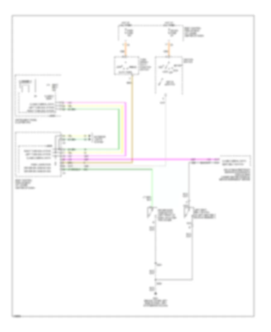
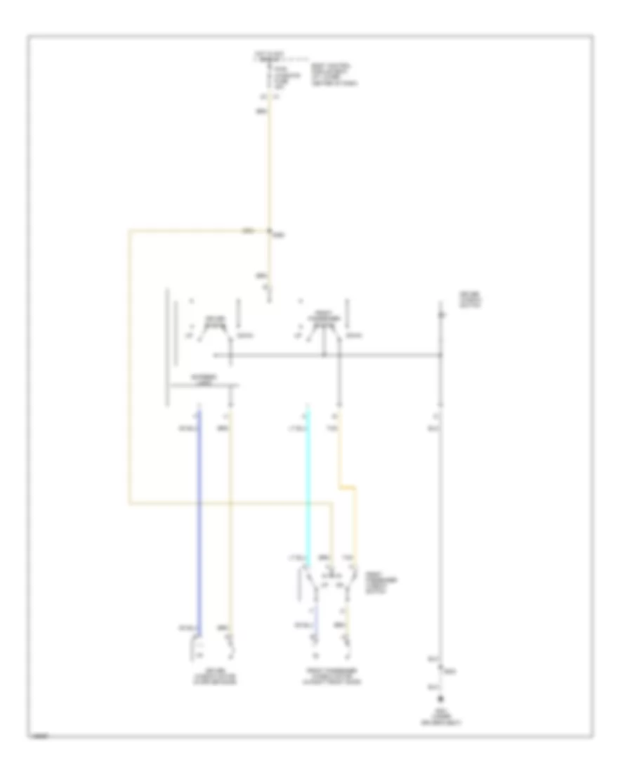
БАГАЖНИК ЗАДНЯЯ ДВЕРЬ ЛЮЧОК ТОПЛИВНОГО БАКА
Электросхема открывания багажника для Saturn Ion Red Line 2004
 https://portal-diagnostov.com/license.html
Automotive Electricians Portal FZCO
Automotive Electricians Portal FZCO
https://portal-diagnostov.com/license.html
https://portal-diagnostov.com/license.html
Automotive Electricians Portal FZCO
Automotive Electricians Portal FZCO
Электросхема открывания багажника для Saturn Ion Red Line 2004 - Список элементов:
- Ajar switch
- B(+)
- Bcm (pwr) fuse 15a
- Body control module (bcm) (at lower center of dash)
- Compartment light breakout)
- Early production
- G301 (under driver's seat)
- G403 (under center of rear shelf)
- G403 (under center of rear shelf)
- Gnd
- Hot at all times
- Interior lights system
- Late production
- Logic
- Rear compartment lid release actuator (in rear compt lid)
- Rear compartment lid release switch
- Release actuator
- S337 (in body harn, 7.5cm from auxiliary power outlet breakout)
- S351
- S990
- Sp403 (in body harn, near right rear speaker)
- Trunk ajar indicator control
- Trunk release motor control
- Valet switch
- W/ rke
БЛОК ПРЕДОХРАНИТЕЛЕЙ И РЕЛЕ
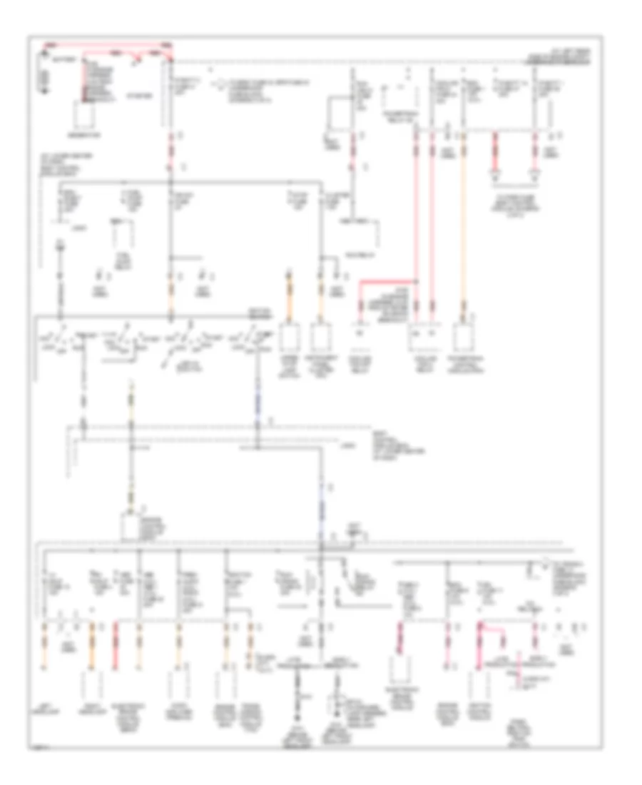
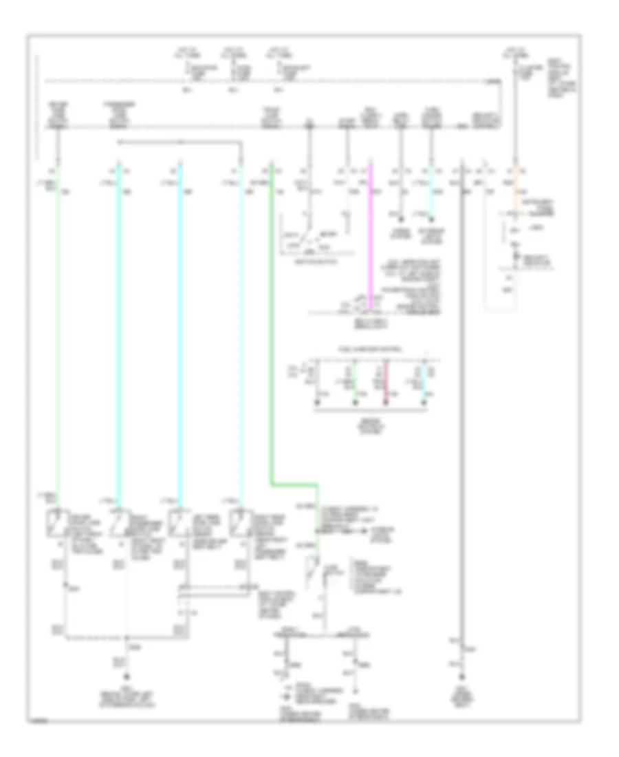
Электросхема блока предохранителей и реле (1 из 3) для Saturn Ion Red Line 2004
Электросхема блока предохранителей и реле (1 из 3) для Saturn Ion Red Line 2004 - Список элементов:
- (2.2l)
- (5 spd a/t)
- (5 spd c1 a/t)
- (at left rear side of engine compt) underhood fuse block
- (at lower center of dash) body control module (bcm)
- (cvt)
- (cvt) c1
- (not used)
- 5v ref
- A/c relay 24
- A10
- A11
- Aa2
- Aa3
- Abs (2.0l) abs 1 (2.2l) fuse 22 20a
- Abs 2 (2.2l) abs (2.0l) fuse 8 10a
- Abs fuse 40a
- Acc
- Audio amplifier (premium)
- B1 c2
- B11 c2
- Ba2
- Battery
- Bcm elect fuse 20a
- Body control module (bcm) (at lower center of dash)
- C1 engine control module (ecm)
- Cluster fuse 7.5a
- Cooling fan 2 fuse 44 30a
- Cooling fan 2 relay
- Cooling fan s/p relay
- E4 c2
- E6 c1
- Early production
- Ecm fuse 1 10a (2.0l)
- Ecm fuse 9 10a (2.2l)
- Ecm/tcm
- Electronic brake control module
- Electronic brake control module (ebcm)
- Engine control module (ecm)
- Fuel pump fuse 15a
- Fuel pump relay
- Fuse 1 10a
- G101 (behind left front headlamp)
- Generator
- Ign fuse 11 10a (2.2l)
- Ign sw fuse 2a
- Ignition control module
- Ignition switch
- Instrument panel cluster (ipc)
- Ip batt 1 fuse 39 30a
- Ip batt 1a fuse 47 30a
- Ip batt 2 fuse 41 40a
- Key-in switch
- Late production
- Left headlamp
- Lh hdlp fuse 18 15a
- Lock
- Lock off
- Logic
- Off
- Park/ neutral position (pnp) switch
- Pnk
- Powertrain control module (pcm)
- Powertrain relay 29
- Prem audio (2.2l) radio (2.0l) fuse 21 20a
- Red
- Rh hdlp fuse 4 15a
- Right headlamp
- Run
- Run (ign 3) fuse 30a
- Run relay
- Run/ crank fuse 38 30a
- Run/ crank relay
- S101
- S150 (in engine harness, 5 cm from engine harness, breakout) red
- S158 (in engine harness, 6 cm from starter solenoid breakout)
- Sp101 (in forward lamp harness, near left headlamp)
- Start
- Starter
- Stop fuse 15a
- To eps1 fuse 43, eps fuse 43 (underhood fuse block) (diagram 2 of 3)
- To park fuse (body control module) (diagram 2 of 3)
- To trans 2 fuse 13 (underhood fuse block) (diagram 3 of 3)
- Trans- mission control module (tcm)
- Upper stop lamp switch
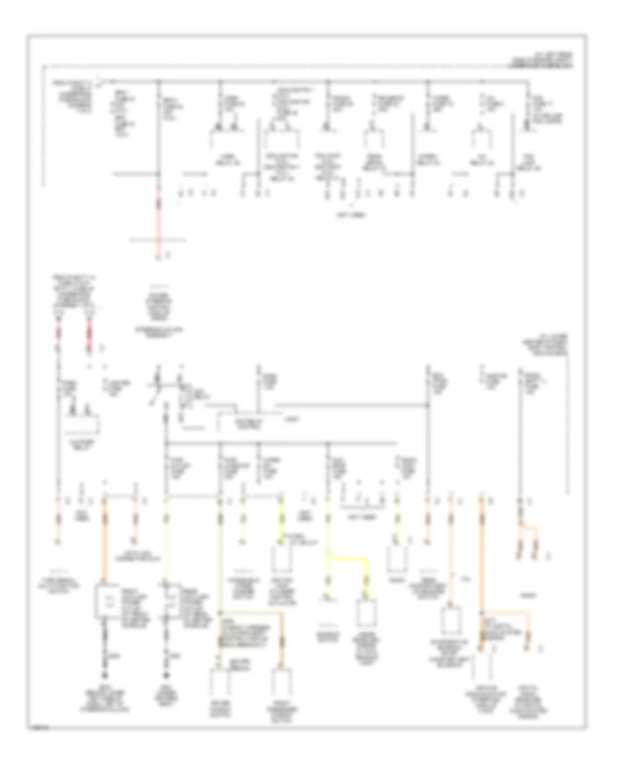
Электросхема блока предохранителей и реле (2 из 3) для Saturn Ion Red Line 2004
Электросхема блока предохранителей и реле (2 из 3) для Saturn Ion Red Line 2004 - Список элементов:
- (at left rear side of engine compt) underhood fuse block
- (at lower center of dash) body control module (bcm)
- (coupe)
- (not used)
- (sedan) c1
- (w/ deluxe fog lamps)
- 2.0l
- 5 spd a/t or cvt
- A/c fuse 5 10a
- A/c relay 24
- Ab1
- Ab2
- Ab3
- Ab4
- Acc relay
- Acc relay control
- Alc/park relay
- B11
- Bb1
- Bb3
- Bcm (pwr) fuse 15a
- Cooling fan (2.2l) cooling fan 1 (2.0l) relay 30
- Cooling fan 1 (2.0l) cooling fan (2.2l) fuse 45 30a
- Crank fuse 46 30a
- D12
- Dash fuse 7.5a
- Data link connector (dlc)
- Digital radio receiver (w/ digital audio system s-band)
- Driver window switch
- E10
- E12
- Eps 1 fuse 43 30a (2.2l)
- Eps 2
- Eps fuse 43 60a (2.0l)
- Evaporative emission (evap) canister vent solenoid
- F12
- Fog fuse 17 10a
- Fog lamp relay 26
- From ip batt 1a fuse 47 & ip batt 1 fuse 48 (underhood fuse block) (diagram 1 of 3)
- From ip batt 2 a fuse 41 (underhood fuse block) (diagram 1 of 3)
- Front auxiliary power outlet (at front of center console)
- Front passenger window switch
- Fuse 42 30a (2.2l)
- G10
- G203 (behind lower left side of dash, left of steering column)
- G301 (under driver's seat)
- Horn fuse 20 10a
- Horn relay 25
- Ignition lock cylinder control actuator
- Inside rearview mirror (w/ dual reading lamp)
- Lighter fuse 15a
- Logic
- Onstar fuse 10a
- Park fuse 15a
- Pcm cont (2.2l) ecm cont (2.0l) relay 31
- Power steering control module (pscm)
- Pwr outlet fuse 15a
- Pwr windows fuse 30a
- Radio
- Radio (acc) fuse 10a
- Radio (batt 1) fuse 10a
- Rear auxiliary power outlet (at rear of center console)
- Rear compartment lid release switch
- Rear defog relay 34
- Red
- Rr defog fuse 23 30a
- S417 (w/ digital audio system s-band)
- Steering column assembly
- Sun roof fuse 15a
- Sunroof switch
- Turn signal/ multi-function switch
- V12
- Vehicle communication interface module (vcim)
- Windshield wiper/ washer switch
- Wiper 1 relay 32
- Wiper fuse 19 25a
- Wiper sw fuse 10a
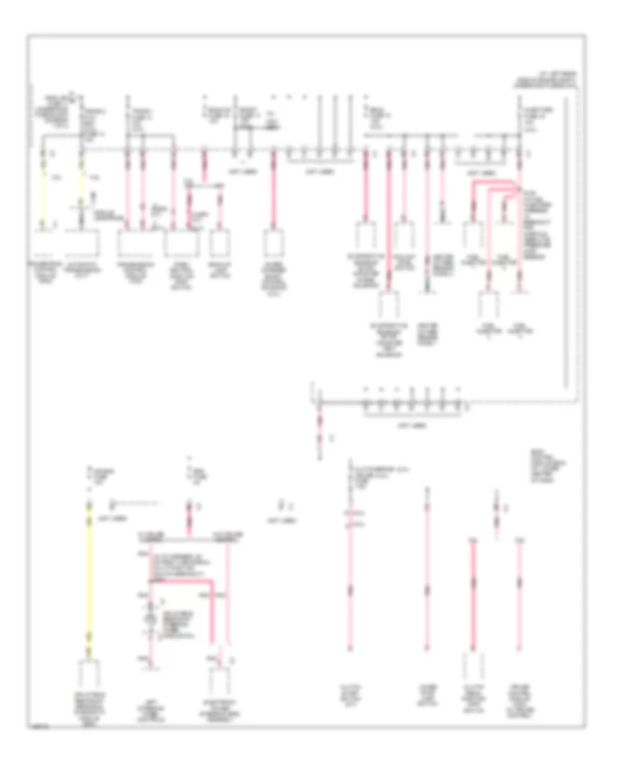
Электросхема блока предохранителей и реле (3 из 3) для Saturn Ion Red Line 2004
Электросхема блока предохранителей и реле (3 из 3) для Saturn Ion Red Line 2004 - Список элементов:
- (2.0l)
- (2.2l)
- (5 spd a/t)
- (5 spd a/t) c1
- (at left rear side of engine compt) underhood fuse block
- (cvt)
- (cvt) c1
- (not used)
- 2.0l
- 2.2l
- 2.2l a/t
- A10
- Air bag fuse 10a
- Automatic transmission (cvt)
- B10
- Back-up fuse 15 10a
- Back-up lamp switch
- Body control module (bcm) (at lower center of dash)
- Boost fuse 14 10a (2.0l)
- C1 pnk
- C10
- C100
- C2 pnk
- Clutch pedal position (cpp) switch
- Clutch start switch (m/t)
- Clutch/brake cruise fuse 7.5a
- Coolant level switch
- Cruise control module (ccm) (w/ cruise control)
- Electronic power steering (eps) assembly
- Eps fuse 2a
- Erls fuse 10 10a (2.2l)
- Evaporative emission (evap) canister purge solenoid
- Evaporative emission (evap) canister vent solenoid
- From ign d fuse 11 (underhood fuse block) (diagram 1 of 3)
- Fuel injector
- Fuse 16 10a
- Heated oxygen sensor (ho2s) 1
- Heated oxygen sensor (ho2s) 2
- Inflatable restraint sensing & diagnostic module (sdm)
- Inflatable restraint steering wheel module coil
- Injectors
- Left steering wheel controls
- Lower stop lamp switch
- M/t
- Module leadframe
- Nca
- Park/ neutral position (pnp) switch
- Pnk
- Pnk (in i/p harness, 22 cm from turn signal/ multi-function switch breakout) s227
- Pnk a
- Powertrain control module (pcm)
- S139 (in fuel injectors harness, at breakout for manifold absolute pressure (map) sensor)
- Super charger boost control solenoid (2.0l)
- Trans 1 fuse 14 10a (2.2l)
- Trans 2 (2.2l) ecm (2.0l) fuse 13 10a
- Transmission control module (tcm)
- W/ cruise control
- W/o cruise control
БЛОКИ УПРАВЛЕНИЯ КУЗОВОМ
Электросхема блоков управления кузовом (1 из 2) для Saturn Ion Red Line 2004
Электросхема блоков управления кузовом (1 из 2) для Saturn Ion Red Line 2004 - Список элементов:
- (sedan) mirrors system (coupe) power tops & mirrors systems
- 5v ref
- A/c request sig
- A10
- Acc pwr
- Acc voltage
- Air conditioning system
- Anti-lock brakes system
- Anti-theft system
- B(+)
- B11
- Bcm class 2 ser data
- Body control module (bcm) (at lower center of dash)
- Computer data lines system
- Defogger system
- Drl amb light sen ref
- Drl amb light sen sig
- Drv dr jamb sw sig
- Engine controls system
- Exterior lights system
- Fog lp rly ctrl
- Fog lp sw sig
- Fuel pump pwr
- Fuel pump rly ctrl
- G101 (behind left front headlamp)
- G201 (behind lower left side of dash, left of steering column)
- Ground
- Headlamps off sig
- Headlights system
- High beam sig
- Horn rly ctrl
- Horns system
- Hot at all times
- Ign 1 pwr
- Ign 3 pwr
- Interior lights system
- Ip batt 1 fuse 39 30a
- Ip batt 1a fuse 47 30a
- Ip batt 2 fuse 41 40a
- Low beam pwr
- Low beam sig
- Low ref
- Lp dim ctrl
- Lt turn sig pwr
- Off/run/crank pwr
- Panel lp pwr
- Park brake sw sig
- Park lp pwr
- Pass dr jamb sw sig
- Pnk
- Power distribution system
- Power distribution system (ignition switch)
- Power windows system
- Pwr window sw lockout ctrl (sedan)
- Rear defog rly ctrl
- Rear defog sw sig
- Red
- Rt turn sig pwr
- Run (ign 3) fuse 48 30a
- Run/ crank fuse 38 30a
- Run/ crank relay
- Run/crank pwr
- S250
- Security ind ctrl
- Shift interlock system
- Shift lk sol pwr
- Sound systems
- Sp101 (in forward lamp harness, near left headlamp)
- Stop lp sw sig
- Trac ctrl ind
- Trac ctrl sw sig
- Turn/haz sw pwr
- Underhood fuse block (2.2l: at left rear side of engine compt)
- Warning system
- Washer pump ctrl
- Wiper sw sig 1
- Wiper/washer system
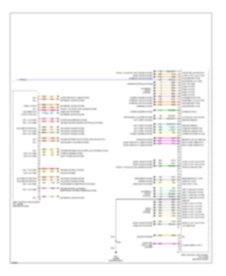
Электросхема блоков управления кузовом (2 из 2) для Saturn Ion Red Line 2004
Электросхема блоков управления кузовом (2 из 2) для Saturn Ion Red Line 2004 - Список элементов:
- Acc voltage
- Air conditioning system
- Anti-theft system
- B(+)
- Bcm class 2 ser data
- Blower motor pwr
- Body control module (bcm) (at lower center of dash)
- Brake fluid lev sen sig
- Class 2 serial data
- Computer data lines system
- Courtesy lp low ctrl
- Cruise control system
- Cruise control system & electronic power steering system
- Cruise control/engine controls systems
- Defogger system
- Door lk act lk ctrl
- Door lk act unlk ctrl
- Door locks system
- Engine controls system
- Exterior lights system
- Fog lp rly ctrl
- G301 (under driver's seat)
- Ground
- Ground (sedan)
- Headlights system
- High beam sig
- Horn rly ctrl
- Horns system
- Ign 1 voltage
- Ign 3 voltage
- Inadvertent pwr
- Instrument cluster system
- Interior lights system
- Left turn sig lp pwr
- Lf dr lk act unlk ctrl
- Lo coolant lev ind sig
- Low beam sig
- Mirrors system
- Park lp pwr
- Pass dr jamb sw sig
- Pnk
- Power distribution system (aux power outlet)
- Power distribution system (ignition switch)
- Rear defog rly ctrl
- Red
- Right turn sig lp pwr
- Run/crank voltage
- S351
- Shift interlock system
- Sound systems
- Starting/charging system
- Stop lp sw sig
- Tan
- Trunk ajar ind ctrl
- Trunk rel motor pwr
- Trunk, tailgate, fuel doors system
- Warning system
- Washer pump ctrl
- Wiper mtr park sw sig
- Wiper sw sig 2
- Wiper/washer system
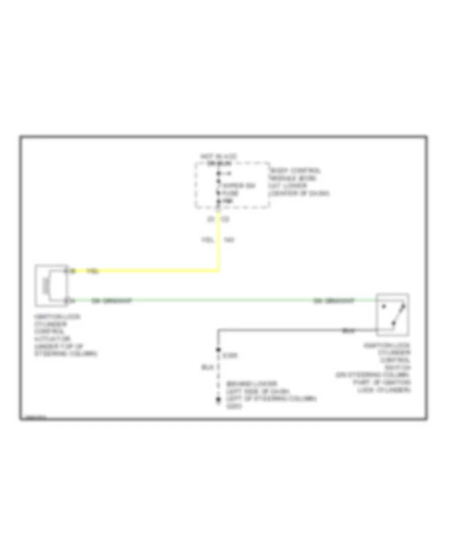
БЛОКИРОВКИ СЕЛЕКТОРА СТОЯНОЧНЫЙ ТОРМОЗ
Электросхема соленоида блокировки замка зажигания для Saturn Ion Red Line 2004
Электросхема соленоида блокировки замка зажигания для Saturn Ion Red Line 2004 - Список элементов:
- (behind lower left side of dash, left of steering column) g203
- Body control module (bcm) (at lower center of dash)
- Hot in acc or run
- Ignition lock cylinder control actuator (under top of steering column)
- Ignition lock cylinder control switch (on steering column, part of ignition lock cylinder)
- S355
- Wiper sw fuse 10a
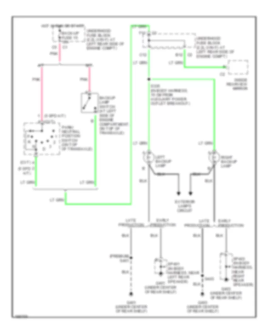
ВНЕШНЕЕ ОСВЕЩЕНИЕ
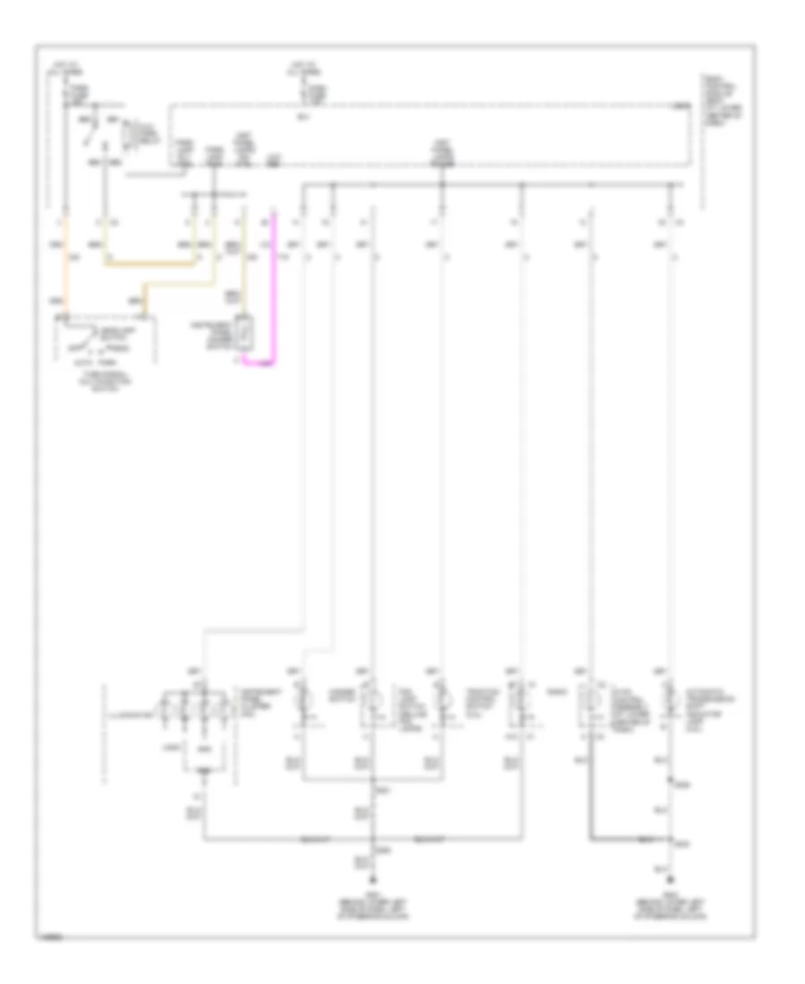
Электросхема заднего хода для Saturn Ion Red Line 2004
Электросхема заднего хода для Saturn Ion Red Line 2004 - Список элементов:
- (5 spd a/t)
- (cvt)
- (premium) s401
- A/t
- Back-up fuse 15 10a
- Backup lamp switch (at left side of engine compartment, on top of transaxle)
- C12
- C2 b12
- Early production
- Exterior lamps circuit
- F11
- G401 (under center of rear shelf)
- G403 (under center of rear shelf)
- Hot in run or start
- Inside rearview mirror
- Late production
- Left backup lamp
- M/t
- Park/ neutral position switch (on top of transaxle)
- Pnk
- Right backup lamp
- S335 (in body harness, 15 cm from auxiliary power outlet breakout)
- S403
- Sp401 (in body harness, near left rear speaker)
- Sp403 (in body harness, near right rear speaker)
- Underhood fuse block (2.2l (vin f): at left rear side of engine compt)
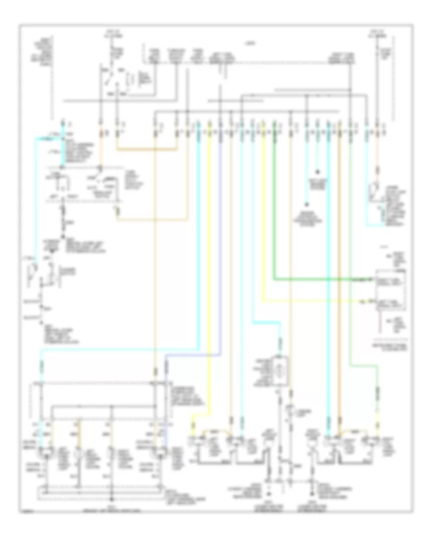
Электросхема внешнего освещения, Дорестайлинг для Saturn Ion Red Line 2004
Электросхема внешнего освещения, Дорестайлинг для Saturn Ion Red Line 2004 - Список элементов:
- (coupe)
- (sedan) a
- (sedan) b
- (sedan) g
- Alc/ park relay
- Anti-lock brakes system
- Auto
- Bb1
- Bb2
- Bb3
- Bb4
- Body control module (bcm) (at lower center of dash)
- C2 f12
- C3 a12
- Center high mounted stop lamp (chmsl) (6 bulbs)
- D11
- E12
- Engine controls/ transmissions system
- G101 (behind left front headlamp)
- G201 (behind lower left side of dash, left of steering column)
- G203 (behind lower left side of dash, left of steering column)
- G401 (under center of rear shelf)
- G403 (under center of rear shelf)
- Hazard switch
- Head
- Headlamp switch
- Hot at all times
- Instrument panel cluster (ipc)
- Interior lights system
- Left
- Left backup lamp
- Left front marker lamp (coupe)
- Left front park/ turn signal lamp
- Left tail/ stop lamp
- Left tail/ turn signal lamp
- Left turn signal ind
- Left turn signal input
- License lamp
- Logic
- Off
- Park
- Park fuse 15a
- Park lamp relay ctrl
- Right
- Right backup lamp
- Right front marker lamp (coupe)
- Right front park/ turn signal lamp
- Right tail/ stop lamp
- Right tail/ turn signal lamp
- Right turn signal ind
- Right turn signal input
- S221
- S260
- S270 (in i/p harness, 5.5 cm from body control module (bcm) breakout)
- S375
- S990
- Sp101 (in forward lamp harness, near left headlamp)
- Sp401 (in body harness, near left rear speaker)
- Sp403 (in body harness, near right rear speaker)
- Stop fuse 15a
- Turn signal/ multi- function switch
- Turn switch
- Underhood fuse block (2.2l (vin f): at left rear side of engine compt)
- Upper stop lamp switch (below left side of dash, attached to brake pedal bracket)
Электросхема внешнего освещения, Посол Рестайлинга для Saturn Ion Red Line 2004
Электросхема внешнего освещения, Посол Рестайлинга для Saturn Ion Red Line 2004 - Список элементов:
- (behind left front headlamp) g101
- (coupe)
- (sedan) a
- (sedan) b
- (sedan) g
- Alc/ park relay
- Anti-lock brakes system
- Auto
- Bb1
- Bb2
- Bb3
- Bb4
- Body control module (bcm) (at lower center of dash)
- C2 f12
- C3 a12
- Center high mounted stop lamp (chmsl) (6 bulbs)
- D11
- E12
- Engine controls/ transmissions system
- G201 (behind lower left side of dash, left of steering column)
- G203 (behind lower left side of dash, left of steering column)
- G401 (under center of rear shelf)
- G403 (under center of rear shelf)
- Hazard switch
- Head
- Headlamp switch
- Hot at all times
- Instrument panel cluster (ipc)
- Interior lights system
- Left
- Left backup lamp
- Left front marker lamp (coupe)
- Left front park/ turn signal lamp
- Left tail/ stop lamp
- Left tail/ turn signal lamp
- Left turn signal ind
- Left turn signal input
- License lamp
- Logic
- Off
- Park
- Park fuse 15a
- Park lamp relay ctrl
- Right
- Right backup lamp
- Right front marker lamp (coupe)
- Right front park/ turn signal lamp
- Right tail/ stop lamp
- Right tail/ turn signal lamp
- Right turn signal ind
- Right turn signal input
- S101
- S221
- S260
- S270 (in i/p harness, 5.5 cm from body control module (bcm) breakout)
- S375
- S401 (premium)
- S403
- S990
- Stop fuse 15a
- Turn signal/ multi- function switch
- Turn switch
- Underhood fuse block (2.2l (vin f): at left rear side of engine compt)
- Upper stop lamp switch (below left side of dash, attached to brake pedal bracket)
ВНУТРЕННЕЕ ОСВЕЩЕНИЕ
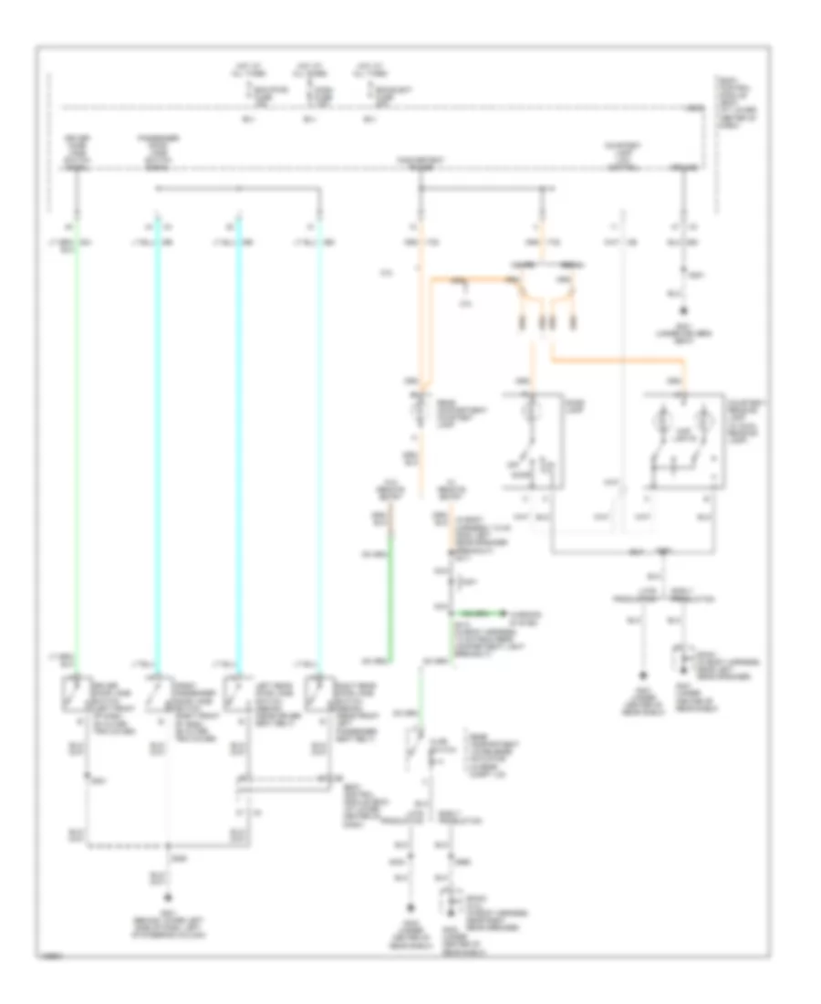
Электросхема подсветки для Saturn Ion Red Line 2004
Электросхема подсветки для Saturn Ion Red Line 2004 - Список элементов:
- (in body harness, 7.5 cm from left rear speaker breakout) s411
- 2.0l
- 2.2l
- Ajar switch
- B(+)
- Bcm (pwr) fuse 15a
- Bcm elect fuse 20a
- Body control module (bcm) (at lower center of dash)
- Coupe
- Courtesy lamp low control
- Courtesy/ reading lamp (w/ dual reading lamp)
- D401
- Dash fuse 7.5a
- Dome lamp
- Door
- Driver door jamb switch (left front of dash, on outer trim cover)
- Driver door jamb switch signal
- Early production
- Front passenger door jamb switch (right front of dash, on outer trim cover)
- G201 (behind lower left side of dash, left of steering column)
- G301 (under driver's seat)
- G401 (under center of rear shelf)
- G403 (under center of rear shelf)
- Ground
- Hot at all times
- Inadvertent power
- Late production
- Left rear door jamb switch (sedan) (near driver seat belt)
- Logic
- Map lights
- Nca
- Off
- Passenger door jamb switch signal
- Rear compartment courtesy lamp
- Rear compartment lid release actuator (in rear compt lid)
- Right rear door jamb switch (sedan) (near front left passenger seat belt)
- S221
- S250
- S351
- S375
- S403
- S413 (in body harness, 7.5 cm from rear compartment light breakout)
- S990
- Sedan
- Sp401 (in body harness, near left rear speaker)
- Sp403 (2.2l) (in body harness, near right rear speaker)
- W/ remote entry
- W/o remote entry
- Warning system
Электросхема подсветки приборов для Saturn Ion Red Line 2004
Электросхема подсветки приборов для Saturn Ion Red Line 2004 - Список элементов:
- A12
- Alc/ park relay
- Auto
- Automatic transmission shift indicator lamp (2.2l)
- B(+)
- Bb1
- Bb2
- Bb3
- Bb4
- Body control module (bcm) (at lower center of dash)
- Dash fuse 7.5a
- Fog lamp switch (deluxe fog lamps)
- G201 (behind lower left side of dash, left of steering column)
- G203 (behind lower left side of dash, left of steering column)
- Gnd
- Hazard switch
- Head
- Headlamp switch
- Hot at all times
- Hvac control assembly (at lower center of dash)
- Illumination
- Inst panel lamps dim ctrl
- Inst panel lamps power
- Instrument panel cluster (ipc)
- Instrument panel dimmer switch
- Logic
- Low ref
- Off
- Park
- Park fuse 15a
- Park lamp pwr
- Park lamp rly ctrl
- Radio
- S221
- S233
- S250
- S355
- Traction control switch (2.2l)
- Turn signal/ multifunction switch
ЗАЗЕМЛЕНИЕ ПОДКЛЮЧЕНИЕ МАССЫ
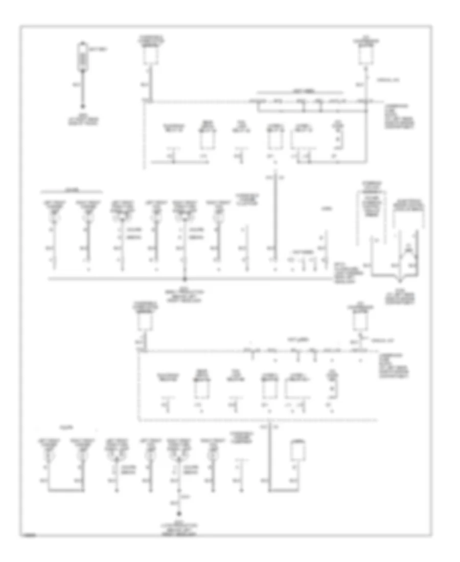
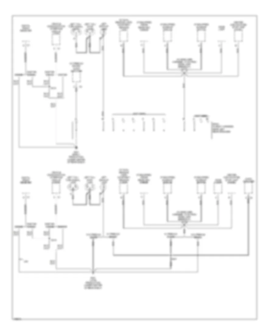
Электросхема подключение массы заземления (1 из 4) для Saturn Ion Red Line 2004
Электросхема подключение массы заземления (1 из 4) для Saturn Ion Red Line 2004 - Список элементов:
- (coupe)
- (not used)
- (sedan)
- A/c compressor clutch
- A/c diode
- A10
- A11
- Battery
- Coupe
- D11
- E17
- Electronic brake control module (ebcm)
- F10
- Fog lamp relay 26
- G101 (early production) (behind left front headlamp)
- G101 (late production) (behind left front headlamp)
- G109 (at left rear side of engine compartment)
- G12
- G502 (at right rear side of trunk)
- Horn
- L10
- L11
- Left front fog lamp
- Left front marker lamp
- Left front park/turn signal lamp
- Manual a/c
- Power steering control module (pscm)
- Q11
- Rear defog relay 34
- Right front fog lamp
- Right front marker lamp
- Right front park/turn signal lamp
- Run/crank relay 28
- S101
- Sp101 (in forward lamp harness, near left headlamp)
- Steering column assembly
- Underhood fuse block (at left rear side of engine compartment)
- V10
- W/ abs
- Windshield washer fluid pump
- Windshield wiper motor assembly
- Wiper 1 relay 32
- Wiper 2 relay 32
Электросхема подключение массы заземления (2 из 4) для Saturn Ion Red Line 2004
Электросхема подключение массы заземления (2 из 4) для Saturn Ion Red Line 2004 - Список элементов:
- (behind lower left side of dash, left of steering column) g201
- (if equipped)
- (if equipped) cruise control module (ccm)
- (in i/p harness, 10 cm from electronic power steering (eps) assembly breakout) s221
- (in i/p harness, 5 cm from ambient light sensor breakout)
- (not used)
- (sedan)
- (under driver's seat) g301
- (w/ cruise control) left steering wheel controls
- 2.2l
- A/t
- A/t shift lock solenoid
- A11
- A12
- Automatic transmission (a/t) shift indicator lamp
- Ba4
- Blower motor
- Body control module (bcm)
- Brake fluid level switch
- Coupe
- Data link connector (dlc)
- Driver door
- Driver door lock switch
- Driver window switch
- Fog lamp switch
- Front auxiliary power outlet
- Front passenger door jamb switch
- Front passenger door lock switch
- Fuel pump & sender assembly
- Fuel pump (fp)
- Fuel pump relay
- G203 (behind lower left side of dash, left of steering column)
- Hazard switch
- Headlamp relay
- Horn switch
- Hvac control assembly
- Ignition lock cylinder control switch
- Inflatable restraint sensing & diagnostic module (sdm)
- Inflatable restraint steering wheel module coil
- Instrument panel cluster (ipc)
- Jamb
- Left rear door jamb switch
- Left seat belt switch
- Logic
- Nca
- Outside rearview mirror switch
- Radio
- Rear auxiliary power outlet
- Red
- Right rear door jamb switch
- S233
- S351 (in body harness, 38.5 cm from auxiliary power outlet breakout)
- S355
- S533 (in driver's door harness, 3.5 cm from driver's door lock switch breakout)
- Sedan
- Sedan & coupe w/ power windows & power mirrors
- Sedan w/o power windows & power mirrors
- Switch
- Traction control switch
- Turn signal/ multi-function switch
Электросхема подключение массы заземления (3 из 4) для Saturn Ion Red Line 2004
Электросхема подключение массы заземления (3 из 4) для Saturn Ion Red Line 2004 - Список элементов:
- (if equipped) inside rearview mirror
- (if equipped) sunroof module
- (if equipped) sunroof switch
- (in headliner harness, 10 cm from dome lamp breakout) s375
- (not used)
- (w/ dual reading lamp) courtesy/ reading lamp
- (w/ premium sound) audio amplifier
- Audio amplifier
- Center high mounted stop lamp (chmsl)
- Digital radio receiver
- Dome lamp
- G401 (early production) (under center of rear shelf)
- G401 (late production) (under center of rear shelf)
- Left backup lamp
- Left tail/ stop lamp
- Left tail/ turn signal lamp
- Onstar
- Onstar/ s-band
- S-band
- S401
- S415
- Sp401 (in body harness, near left rear speaker)
- U2k
- Vehicle communication interface module (vcim)
- W/ premium sound
- W/o premium sound
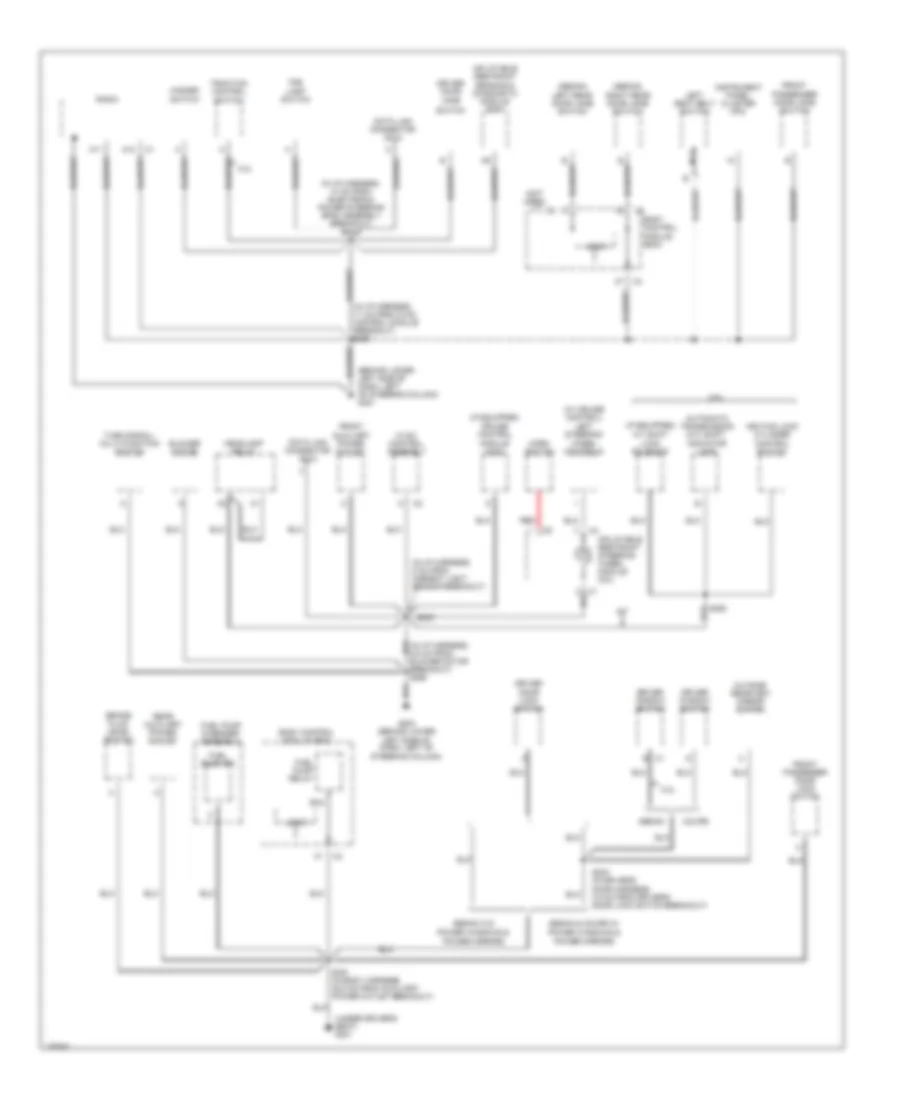
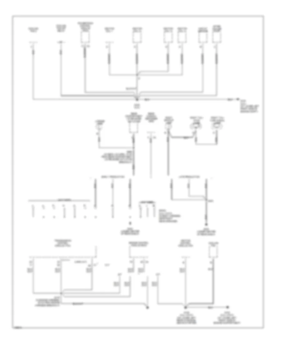
Электросхема подключение массы заземления (4 из 4) для Saturn Ion Red Line 2004
Электросхема подключение массы заземления (4 из 4) для Saturn Ion Red Line 2004 - Список элементов:
- (not used)
- 5 spd (a/t)
- A/t
- After cooler pump
- Cooling fan
- Cooling fan 2
- Cooling fan s/p relay
- Cvt
- Early production
- Engine control module (ecm)
- G103 (2.0l) (at lower left front side of engine compt)
- G103 (2.2l (vin f)) (at lower left front side of engine compartment)
- G105 (2.0l)
- G105 (2.2l (vin f)) (on lower left rear of engine, above starter)
- G403 (under center of rear shelf)
- Ignition coil 1
- Ignition coil 2
- Ignition coil 3
- Ignition coil 4
- Ignition control module (icm)
- Late production
- License lamp
- M/t
- Maf/iat sensor
- Powertrain control module (pcm)
- Rear compartment lid release actuator
- Rear window defogger grid
- Right backup lamp
- Right tail/ stop lamp
- Right tail/ turn signal lamp
- S175 (in engine harness, 35 cm from engine harness breakout)
- S403
- S990 (in deck lid harn, 10 cm from rear compartment lid release actuator breakout)
- Sp403 (2.2l (vin f)) (in body harness, near right rear speaker)
- Transmission control module (tcm)
Звуковой сигнал Гудок
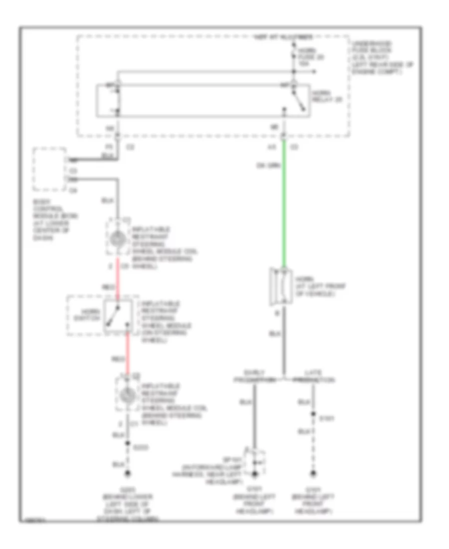
Электросхема звукового сигнал Гудка для Saturn Ion Red Line 2004
Электросхема звукового сигнал Гудка для Saturn Ion Red Line 2004 - Список элементов:
- (behind left front headlamp)
- Body control module (bcm) (at lower center of dash)
- Early production
- G101
- G101 (behind left front headlamp)
- G203 (behind lower left side of dash, left of steering column)
- Horn (at left front of vehicle)
- Horn fuse 20 10a
- Horn relay 25
- Horn switch
- Hot at all times
- Inflatable restraint steering wheel module (on steering wheel)
- Inflatable restraint steering wheel module coil (behind steering wheel)
- Late production
- Red
- S101
- S233
- Sp101 (in forward lamp harness, near left headlamp)
- Underhood fuse block (2.2l (vin f): left rear side of engine compt)
Магнитола Мультимедия
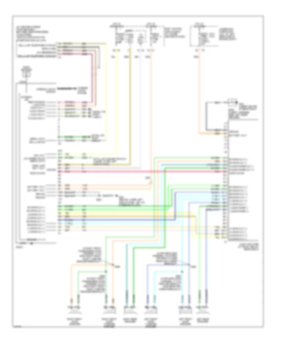
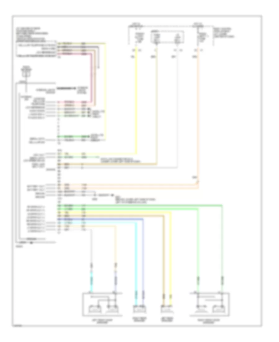
Электросхема магнитолы, С усилитель для Saturn Ion Red Line 2004
Электросхема магнитолы, С усилитель для Saturn Ion Red Line 2004 - Список элементов:
- (2.0l) (2.2l)
- (at center of rear package shelf, between rear speakers) (if equipped) vehicle communication
- (in driver's door harness, 19 cm from driver's outside rearview mirror breakout)
- (in right front passenger's door harness, 13 cm from right front door tweeter speaker breakout)
- A10
- A11
- A12
- Acc volt
- Antenna sig
- Audio amplifier (in trunk, below rear shelf)
- Audio cmmon
- Audio out (-)
- B10
- B11
- B12
- B7 dimming
- Bare
- Battery volt
- Body control module (bcm) (at lower center of dash)
- Case interior lights dimming
- Cellular sig
- Cellular telephone mute sig
- Cellular telephone voice sig
- Coax
- Data link connector (dlc) (under lower left side of dash)
- Drain wire
- G201 (behind lower left side of dash, left of steering column)
- G401 (under center of rear shelf)
- Ground
- Hot at all times
- Hot in acc or run
- I/p lamp sply volt
- Interface module (vcim)
- Interior lights system
- L audio sig (+)
- L subwoofer (+)
- L subwoofer (-)
- Left front door speaker
- Left front door tweeter speaker
- Left rear speaker
- Lf spkr out (+)
- Lf spkr out (-)
- Logic
- Low reference
- Low speed gmlan serial data
- Lr spkr out (+)
- Lr spkr out (-)
- Nca
- Park lamp sply volt
- Pnk
- R audio sig (+)
- R subwoofer out (+)
- R subwoofer out (-)
- Radio
- Radio (acc) fuse 10a
- Radio (batt 1) fuse 10a
- Radio antenna
- Radio on sig
- Radio prem audio fuse 21 20a
- Remote radio l audio sig
- Rf spkr out (+)
- Rf spkr out (-)
- Right front door speaker
- Right front door tweeter speaker
- Right rear speaker
- Rr spkr out (+)
- Rr spkr out (-)
- S250
- S555
- S557 (in driver's door harness, 11.5 cm from driver's out side rearview mirror breakout)
- S656
- S658 (in right front passenger's door harness, 5.5 cm from right front door tweeter speaker breakout)
- Satellite radio circuit
- Serial data
- Sp401 (in body harness, near left rear speaker)
- Tan
- Underhood fuse block (2.2l: at left rear side of engine compt)
Электросхема магнитолы, без Усилитель для Saturn Ion Red Line 2004
Электросхема магнитолы, без Усилитель для Saturn Ion Red Line 2004 - Список элементов:
- (at center of rear package shelf, between rear speakers) (if equipped) vehicle communication interface module (vcim)
- A10
- A11
- A12
- Acc volt
- Antenna sig
- Audio cmmon
- B10
- B11
- B12
- Bare
- Battery volt
- Body control module (bcm) (at lower center of dash)
- Case
- Cellular sig
- Cellular telephone mute sig
- Cellular telephone voice sig
- Coax
- Data link connector (dlc) (under lower left side of dash)
- Dimming
- Drain wire
- G201 (behind lower left side of dash, left of steering column)
- Ground
- Hot at all times
- Hot in acc or run
- I/p lamp sply volt
- Interior lights dimming
- Interior lights system
- L audio sig (+)
- Left front door speaker
- Left rear speaker
- Lf spkr out (+)
- Lf spkr out (-)
- Logic
- Low reference
- Lr spkr out (+)
- Lr spkr out (-)
- Nca
- Park lamp sply volt
- R audio sig (+)
- Radio
- Radio (acc) fuse 10a
- Radio (batt 1) fuse 10a
- Radio antenna
- Rf spkr out (+)
- Rf spkr out (-)
- Right front door speaker
- Right rear speaker
- Rr spkr out (+)
- Rr spkr out (-)
- S250
- Satellite radio circuit
- Serial data
- Serial data low speed gmlan
- Tan
- Voice sig cellular telephone
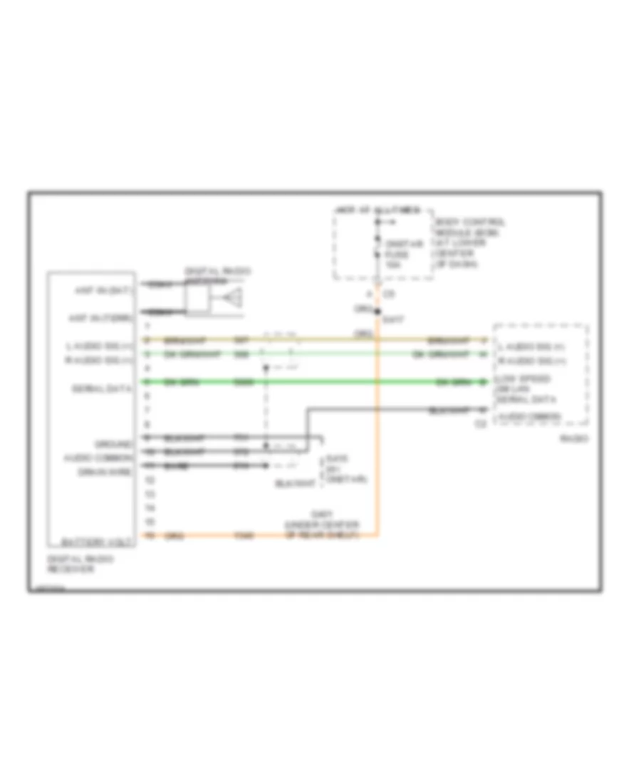
Электросхема спутникового радио для Saturn Ion Red Line 2004
Электросхема спутникового радио для Saturn Ion Red Line 2004 - Список элементов:
- Ant in (sat)
- Ant in (terr)
- Audio cmmon
- Audio common
- Bare
- Battery volt
- Body control module (bcm) (at lower center of dash)
- C5 a
- Coax
- Digital radio antenna
- Digital radio receiver
- Drain wire
- G401 (under center of rear shelf)
- Gm lan serial data
- Ground
- Hot at all times
- L audio sig (+)
- Low speed b
- Onstar fuse 10a
- R audio sig (+)
- Radio
- S417
- Serial data
Подогрев стекол и зеркал
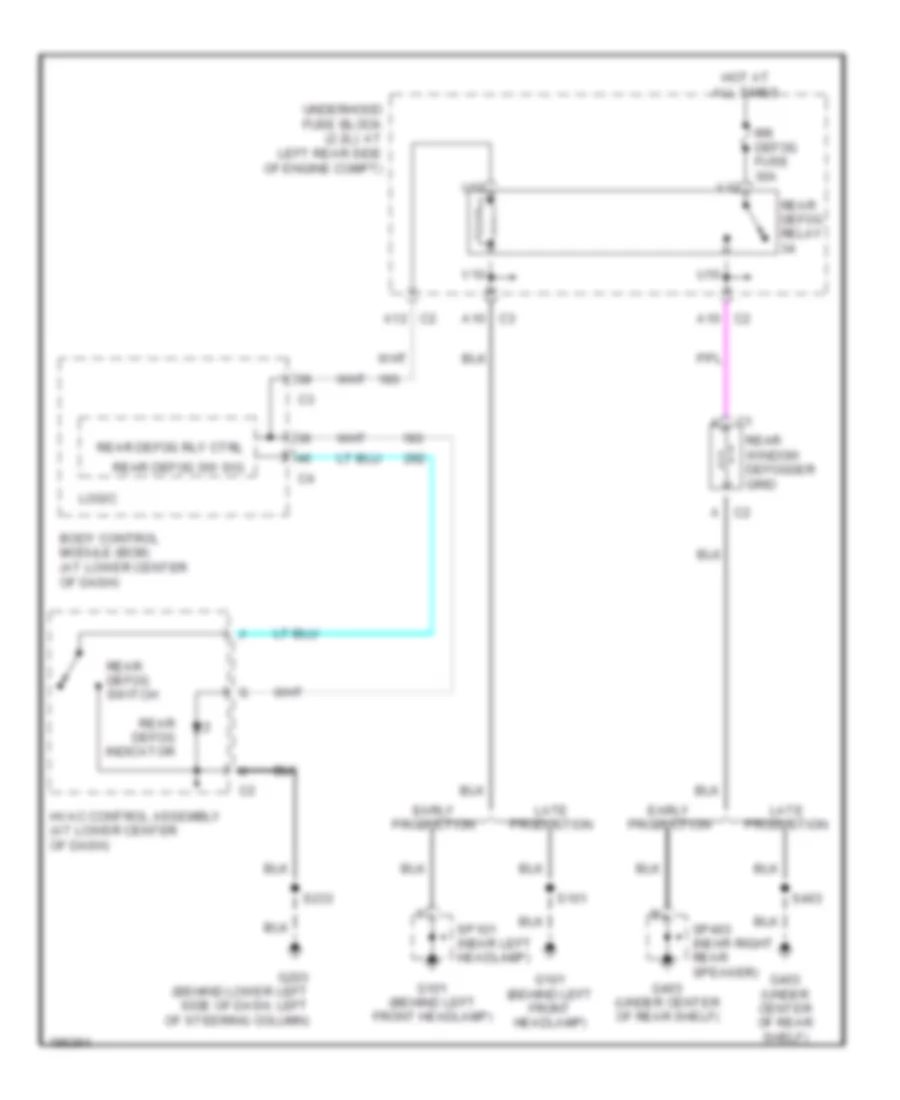
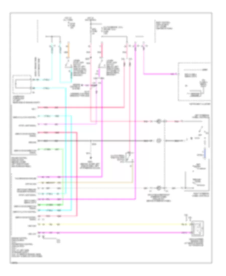
Электросхема подогрева стекол и зеркал для Saturn Ion Red Line 2004
Электросхема подогрева стекол и зеркал для Saturn Ion Red Line 2004 - Список элементов:
- Body control module (bcm) (at lower center of dash)
- C2 a
- C2 a10
- C2 a12
- C3 a10
- Early production
- G101 (behind left front headlamp)
- G203 (behind lower left side of dash, left of steering column)
- G403 (under center of rear shelf)
- Hot at all times
- Hvac control assembly (at lower center of dash)
- Late production
- Logic
- Rear defog indicator
- Rear defog relay
- Rear defog rly ctrl
- Rear defog sw sig
- Rear defog switch
- Rear window defogger grid
- Rr defog fuse 30a
- S101
- S233
- S403
- Sp101 (near left headlamp)
- Sp403 (near right rear speaker)
- U10
- U12
- Underhood fuse block (2.2l): at left rear side of engine compt)
- V10
- V12
ПОДУШКИ БЕЗОПАСНОСТИ AIR BAG
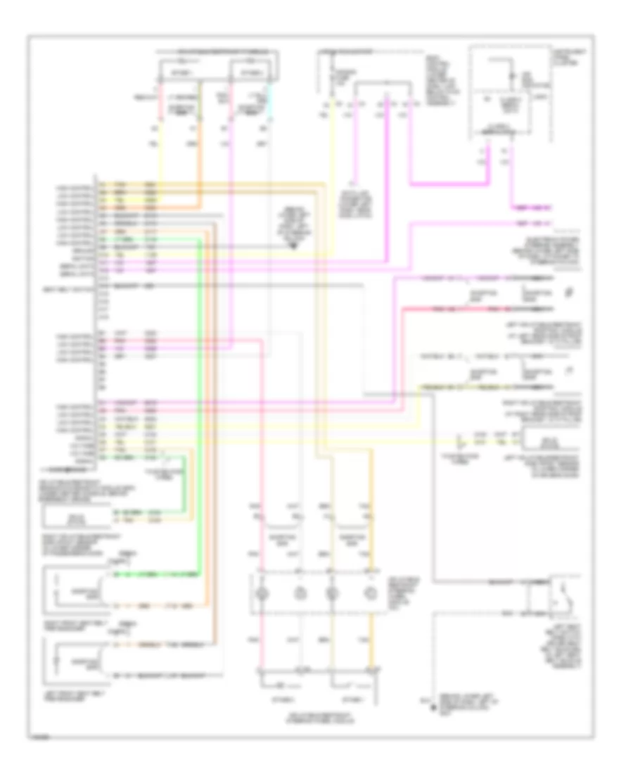
Электросхема подушек безопасности SRS AirBag для Saturn Ion Red Line 2004
Электросхема подушек безопасности SRS AirBag для Saturn Ion Red Line 2004 - Список элементов:
- (behind lower left side of dash, left of steering column) g201
- A10
- A11
- A12
- A13
- A14
- A15
- A16
- A17
- A18
- Air bag fuse 10a
- Air bag indicator
- Body control module (lower center of dash, just below hvac control assembly)
- Case ground
- Class 2 serial data
- Coupe
- Data link connector (lower left dash, near hood latch)
- Electronic power steering assembly (behind lower left side of dash, attached to steering column)
- Ground
- High control
- Hot in run & start
- Ignition
- Inflatable restraint ip module
- Inflatable restraint sensing & diagnostic module (sdm) (under center console, behind emergency brake)
- Inflatable restraint steering wheel module
- Inflatable restraint steering wheel module coil
- Instrument panel cluster
- Left front seat belt pretensioner
- Left inflatable restraint roof rail module (at left rear side of roof bracket, in "c" pillar)
- Left inflatable restraint side impact sensor (in lower corner of driver's door)
- Left seat belt switch (open with driver seat belt buckled) (in left seat belt buckle assembly)
- Logic
- Low control
- Nca
- Pnk
- Right front seat belt pretensioner
- Right inflatable restraint roof rail module (at right rear side of roof bracket, in "c" pillar)
- Right inflatable restraint side impact sensor (in lower corner of passenger's door)
- Seat belt switch
- Sedan
- Serial data
- Shorting bar
- Signal
- Solid state
- Stage 1
- Stage 2
- Tan
- Twisted pair wires
- Voltage
ПРЕДУПРЕЖДАЮЩИЕ СИСТЕМЫ
Электросхема предупреждающей системы для Saturn Ion Red Line 2004
Электросхема предупреждающей системы для Saturn Ion Red Line 2004 - Список элементов:
- A11
- A14
- Acc
- Auto
- Body control module (bcm) (at lower center of dash)
- Chime
- Class 2 (sdm)
- Class 2 serial data
- Driver door jamb switch (left front of dash, on outer trim cover)
- Driver dr jamb sw sig
- Exterior lights system
- G201 (behind lower left side of dash, left of steering column)
- Head
- Hot at all times
- Ign sw fuse 2a
- Ignition switch
- Inflatable restraint sensing & diagnostic module (sdm) (under center console, behind emergency brake)
- Instrument panel cluster (ipc)
- Key-in switch
- Left seat belt switch (in left seat belt buckle assembly)
- Left turn sig lp pwr
- Lock off
- Logic
- Nca
- Off
- Park
- Park fuse 15a
- Park lamps pwr
- Right turn sig lp pwr
- Run
- S221
- S250
- Seat belt ind
- Seat belt switch
- Start
- Turn signal/ multi- function switch
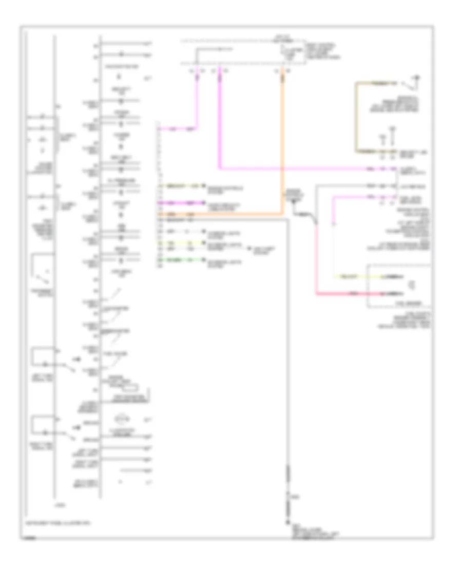
ПРИБОРНАЯ ПАНЕЛЬ
Электросхема панели приборов для Saturn Ion Red Line 2004
Электросхема панели приборов для Saturn Ion Red Line 2004 - Список элементов:
- 2.0l
- 2.2l
- Abs ind
- Air bag ind
- Anti-theft system
- Body control module (bcm) (at lower center of dash)
- Brake ind
- Charge ind
- Class 2 (bcm)
- Class 2 (bcm/ecm/ eps/ebcm)
- Class 2 (ebcm)
- Class 2 (ecm)
- Class 2 (sdm)
- Class 2 serial data
- Cluster fuse 7.5a
- Computer data lines system
- Engine control module (ecm) (2.2l) (at left side of engine compt) powertrain control module (pcm) (2.0l) (at rear of engine, near coolant overflow container)
- Engine controls system
- Engine coolant temp gauge
- Engine oil pressure switch (on lower left side of engine, above starter)
- Exterior lights system
- Fuel gauge
- Fuel level sen signal
- Fuel pump & sender assembly (under right rear vehicle, inside fuel tank)
- Fuel sender
- G201 (behind lower left side of dash, left of steering column)
- Gauge pointer illumination
- Ground
- High beam ind
- Hot at all times
- Illumination (6 bulbs)
- Instrument panel cluster (ipc)
- Interior lights system
- Ipc class 2 serial data
- Left turn signal ind
- Left turn signal input
- Logic
- Low ref bus
- Malfunction ind
- Nca
- Oil pressure ind
- Pnk
- Right turn signal ind
- Right turn signal input
- S250
- Seat belt ind
- Security ind
- Security led driver
- Speedometer
- Tachometer
- Trip odometer/ message center
- Trip/ odometer message center illum
- Trip/reset switch
- Up-shift ind
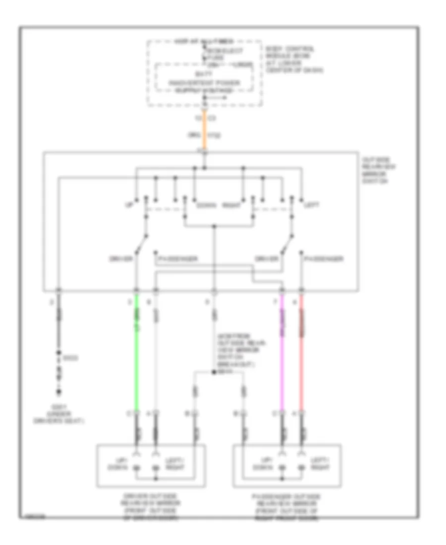
ПРИВОД ЗЕРКАЛ
Электросхема привода зеркал для Saturn Ion Red Line 2004
Электросхема привода зеркал для Saturn Ion Red Line 2004 - Список элементов:
- (4cm from outside rear- view mirror switch breakout) s511
- Batt
- Bcm elect fuse 20a
- Body control module (bcm) (at lower center of dash)
- Down
- Driver
- Driver outside rearview mirror (front outside of driver door)
- G301 (under driver's seat)
- Hot at all times
- Left
- Left/ right
- Logic
- Nca
- Outside rearview mirror switch
- Passenger
- Passenger outside rearview mirror (front outside of right front door)
- Right
- S533
- Up/ down
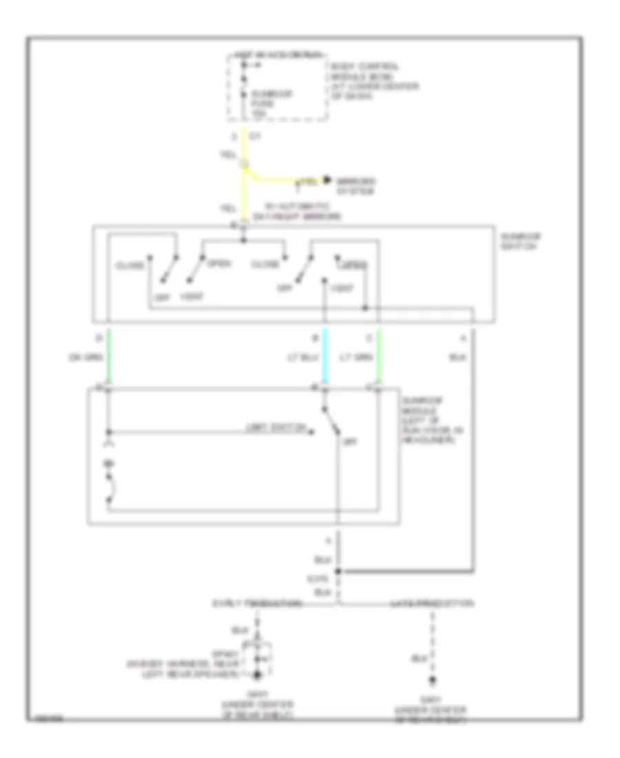
ПРИВОД ЛЮКА И КРЫШИ
Электросхема привода люка или крыши для Saturn Ion Red Line 2004
Электросхема привода люка или крыши для Saturn Ion Red Line 2004 - Список элементов:
- Body control module (bcm) (at lower center of dash)
- Close
- Early production
- G401 (under center of rear shelf)
- Hot in acc or run
- Late production
- Limit switch
- Mirrors system
- Off
- Open
- S375
- Sp401 (in body harness, near left rear speaker)
- Sunroof fuse 15a
- Sunroof module (left of sun visor, in headliner)
- Sunroof switch
- Vent
- Vent off
- W/ automatic day/night mirrors
ПРИВОД СТЕКЛОПОДЪЕМНИКОВ
Электросхема стеклоподъемников, Купе для Saturn Ion Red Line 2004
Электросхема стеклоподъемников, Купе для Saturn Ion Red Line 2004 - Список элементов:
- Body control module (bcm) (at lower center of dash)
- Down
- Driver switch
- Driver window motor (in driver door)
- Driver window switch
- Express logic
- Front passenger switch
- Front passenger window motor (in right front door)
- Front passenger window switch
- G301 (under driver's seat)
- Hot in acc or run
- Pwr windows fuse 30a
- S360
- S533
- Tan
Противоугонная система Сигнализация
Электросхема противоугонной сигнализации для Saturn Ion Red Line 2004
Электросхема противоугонной сигнализации для Saturn Ion Red Line 2004 - Список элементов:
- (2.0l: near coolant overflow container) (2.2l: at left side of engine compt) (2.0l) powertrain control module (pcm) (2.2l (vin f)) engine control module (ecm)
- (in body harness, 7.5 cm from rear compartment light breakout) s413
- (near driver seat belt)
- (near front left passenger seat belt)
- 2.0l
- 2.2l
- 5v ref
- Acc
- Ajar switch
- B(+)
- Bcm (pwr) fuse 15a
- Bcm class 2 serial data
- Bcm elect fuse 7.5a
- Body control module (bcm) (at lower center of dash)
- C2 c2
- Cluster fuse 7.5a
- Dash fuse 7.5a
- Driver door jamb switch (left front of dash, on outer trim cover)
- Driver door jamb switch signal
- Early production
- Ecm class 2 serial data
- Engine controls system
- Exterior lights system
- Front passenger door jamb switch (right front of dash, on outer trim cover)
- Fuel injector control
- G201 (behind lower left side of dash, left of steering column)
- G301 (under driver's seat)
- G403 (under center of rear shelf)
- Gnd
- Horn relay ctrl
- Horns system
- Hot at all times
- Ignition switch
- Instrument panel cluster
- Interior lights system
- Late production
- Left rear door jamb switch (sedan)
- Lock
- Logic
- Nca
- Off
- Passenger door jamb switch signal
- Rear compartment lid release actuator (in rear compartment lid)
- Right rear door jamb switch (sedan)
- Run
- S221
- S250
- S351
- S990
- Security indicator
- Security indicator control
- Sp403 (in body harness, near right rear speaker)
- Start
- Start signal
- Trunk ajar switch signal
- Turn/ hazard switch power
СИСТЕМА АНТИБЛОКИРОВОЧНОЙ ТОРМОЗНОЙ СИСТЕМЫ ABS
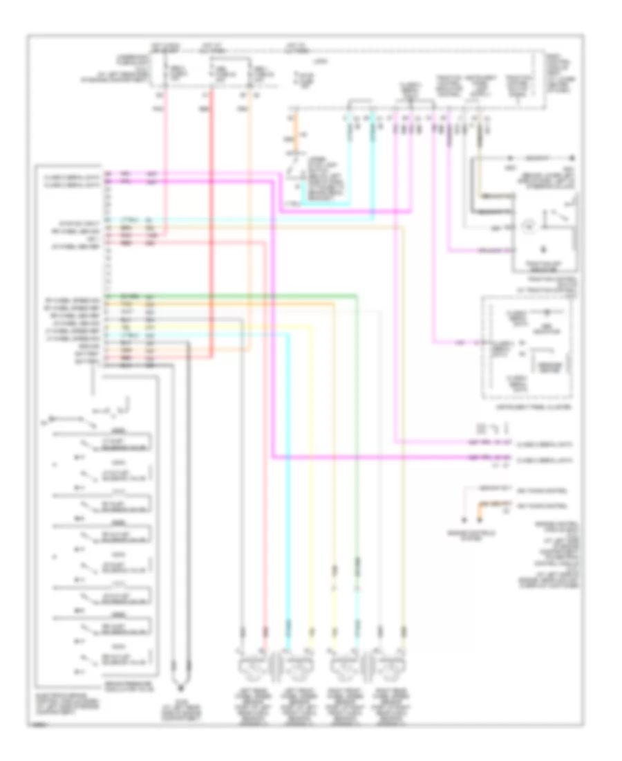
Электросхема антиблокировочной тормозной системы АБС (ABS) для Saturn Ion Red Line 2004
Электросхема антиблокировочной тормозной системы АБС (ABS) для Saturn Ion Red Line 2004 - Список элементов:
- 2.2l 2.0l
- Abs 1 fuse 22 20a
- Abs 2 fuse 8 10a
- Abs fuse 40 40a
- Abs indicator
- Battery
- Body control module (bcm) (at lower center of dash)
- Brake pressure modulator valve
- Class 2 serial data
- Electronic brake control module (ecbm) (at left side of engine compartment)
- Engine control module (ecm) (2.2l) (at left side of engine compartment) powertrain control module (2.0l) (at left side of engine, near coolant overflow container)
- Engine controls system
- G109 (at left rear side of engine compartment)
- G201 (behind lower left side of dash, left of steering column)
- Ground
- Hot at all times
- Hot in run or start
- Ign 1
- Ign timing control
- Instrument panel cluster
- Left front wheel speed sensor (part of left front hub & bearing assembly)
- Left rear wheel speed sensor (part of left rear hub & bearing assembly)
- Lf inlet solenoid valve
- Lf outlet solenoid valve
- Lf wheel speed ref
- Lf wheel speed sig
- Logic
- Lr inlet solenoid valve
- Lr outlet solenoid valve
- Lr wheel sen ref
- Lr wheel sen sig
- Message center
- Pnk
- Red
- Rf inlet solenoid valve
- Rf outlet solenoid valve
- Rf wheel speed ref
- Rf wheel speed sig
- Right front wheel speed sensor (part of right front hub & bearing assembly)
- Right rear wheel speed sensor (part of right rear hub & bearing assembly)
- Rr inlet solenoid valve
- Rr outlet solenoid valve
- Rr wheel sen ref
- Rr wheel sen sig
- S221
- Stop fuse 15a
- Stop sw input
- Tan
- Traction control indicator control
- Traction control switch (w/ traction control) (2.2l)
- Traction control switch signal
- Traction off indicator
- Underhood fuse block (2.2l) (at left rear side of engine compartment)
- Upper stop lamp switch (below left side of dash, attached to brake pedal bracket)
СИСТЕМА КОНДИЦИОНЕРА
Электросхема компрессора для Saturn Ion Red Line 2004
Электросхема компрессора для Saturn Ion Red Line 2004 - Список элементов:
- (at rear of engine, near coolant overflow container) (2.0l) powertrain control module (pcm)
- (not used)
- +5v
- 2.0l
- 2.2l
- A/c compressor clutch (at lower left front of engine)
- A/c diode
- A/c fuse 5 10a
- A/c on led
- A/c on/off
- A/c press
- A/c refrigerant pressure sensor (on lower left side of engine, below generator)
- A/c relay
- A/c request
- A/c switch
- A10
- Aa1
- Aa2
- Aa3
- Aa4
- B11
- Body control module (bcm) (at lower center of dash)
- Class 2 data
- Early production
- Ect sens
- Engine control module (ecm) (2.2l) (at left side of engine compt)
- Engine coolant temperature (ect) sensor (2.0l: on top of engine, near right front corner of camshaft cover) (2.2l (vin f): on right rear side of engine, near exhaust manifold)
- F10
- G101 (behind left front headlamp)
- G203 (behind lower left side of dash, left of steering column)
- Hot at all times
- Hot in run or start
- Hvac control assembly (at lower center of dash)
- Hvac fan switch
- Hvac fuse 7.5a
- Ign 3 volt
- Late production
- Logic
- Low ref
- Off
- Red
- Run (ign 3) fuse 48 30a
- Run relay
- Run relay ctrl
- Run/ crank relay
- S101
- S233 (in i/p harness, 5 cm from ambient light sensor breakout)
- Sp101 (in forward lamp harness, near left headlamp)
- Underhood fuse block (2.2l (vin f): at left rear side of engine compartment)
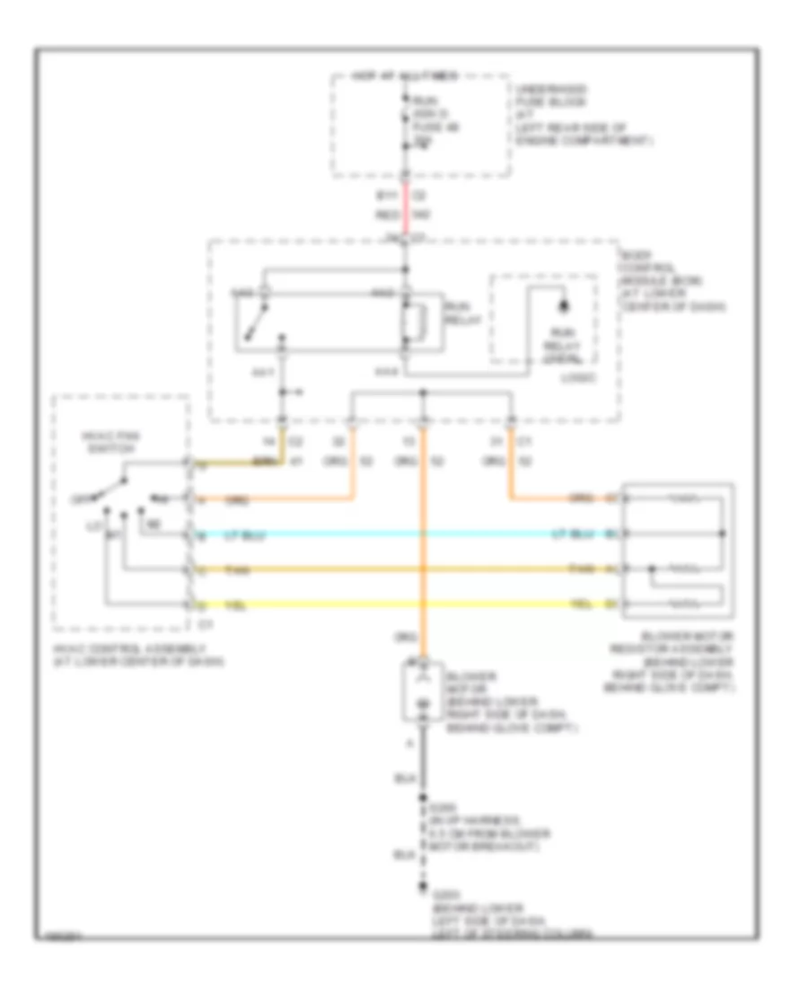
схема нагревателя для Saturn Ion Red Line 2004
схема нагревателя для Saturn Ion Red Line 2004 - Список элементов:
- Aa1
- Aa2
- Aa3
- Aa4
- B11
- Blower motor (behind lower right side of dash, behind glove compt)
- Blower motor resistor assembly (behind lower right side of dash, behind glove compt)
- Body control module (bcm) (at lower center of dash)
- G203 (behind lower left side of dash, left of steering column)
- Hot at all times
- Hvac control assembly (at lower center of dash)
- Hvac fan switch
- Logic
- Off
- Red
- Run (ign 3) fuse 48 30a
- Run relay
- Run relay cntrl
- S260 (in i/p harness, 6.5 cm from blower motor breakout)
- Tan
- Underhood fuse block (at left rear side of engine compartment)
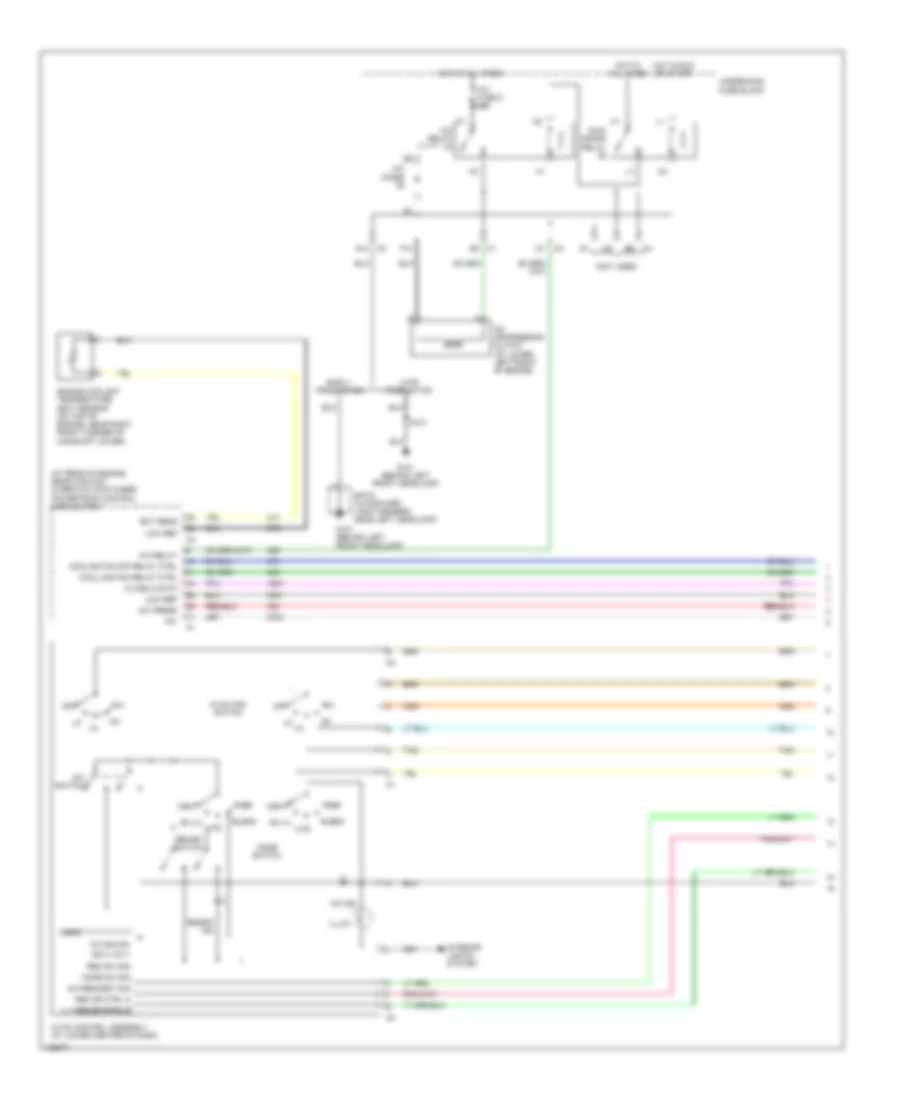
Электросхема кондиционера с ручный управлением (1 из 2) для Saturn Ion Red Line 2004
Электросхема кондиционера с ручный управлением (1 из 2) для Saturn Ion Red Line 2004 - Список элементов:
- (at rear of engine, near coolant overflow container) powertrain control module (pcm)
- (not used)
- +5v
- A/c compressor clutch (at lower left front of engine)
- A/c diode
- A/c fuse 5 10a
- A/c ind
- A/c press
- A/c relay
- A/c request sig
- A/c sig sw
- A/c switch
- A10
- Bi-lvl
- Blend
- Class 2 data
- Cooling fan s/p relay ctrl
- Coolling fan relay ctrl
- Def
- Early production
- Ect sens
- Engine coolant temperature (ect) sensor (on top of engine, near right front corner of camshaft cover)
- F10
- G101 (behind left front headlamp)
- Hot at all times
- Hot in run or start
- Htr
- Hvac control assembly (at lower center of dash)
- Hvac fan switch
- Ign 3 volt
- Illum
- Interior lights system
- Late production
- Logic
- Low ref
- Mode sw sig
- Mode switch
- Off
- Rec dr ctrl a
- Rec dr ctrl b
- Rec sw sig
- Recirc ind
- Recirc switch
- Run/ crank relay
- S101
- Sp101 (in forward lamp harness, near left headlamp)
- Tan
- Underhood fuse block
- Vent
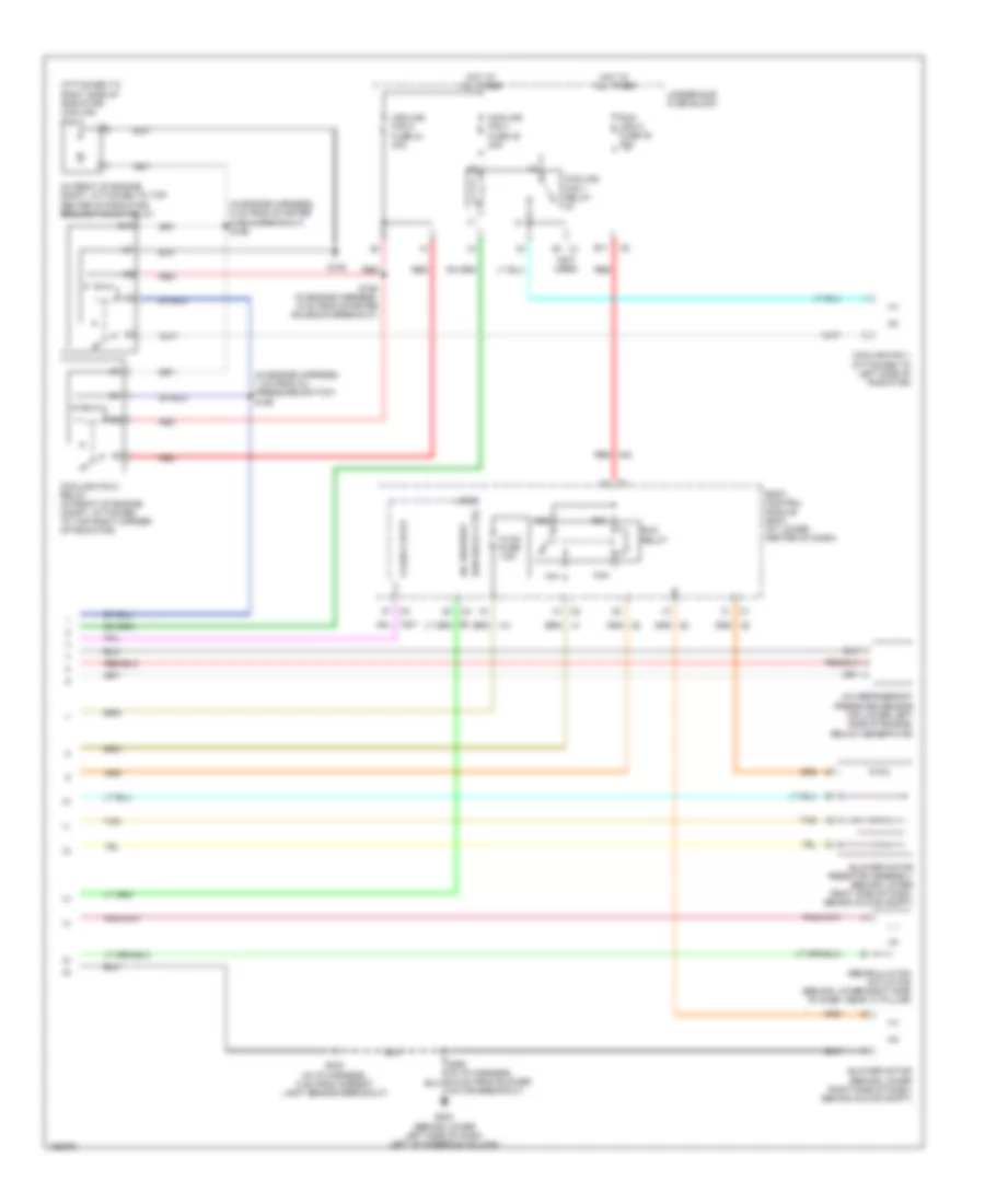
Электросхема кондиционера с ручный управлением (2 из 2) для Saturn Ion Red Line 2004
Электросхема кондиционера с ручный управлением (2 из 2) для Saturn Ion Red Line 2004 - Список элементов:
- (attached to right side of radiator) cooling fan 2
- (in engine harness, 1 cm from oil pressure switch) s160
- (in engine harness, 5 cm from starter cable breakout) s156
- (in front of engine compt, attached to top center of radiator) cooling fan s/p relay
- (not used)
- 87a
- A/c refrigerant pressure sensor (on lower left side of engine, below generator)
- A/c request
- Aa1
- Aa2
- Aa3
- Aa4
- B11
- Blower motor (behind lower right side of dash, behind glove compt)
- Blower motor resistor assembly (behind lower right side of dash, behind glove compt)
- Body control module (bcm) (at lower center of dash)
- Class 2 data
- Cooling fan 1 (attached to left side of radiator)
- Cooling fan 1 fuse 45 30a
- Cooling fan 1 relay
- Cooling fan 2 fuse 44 30a
- Cooling fan 2 relay (in front of engine compt, attached to top right corner of radiator)
- E1 c1
- G105
- G203 (behind lower left side of dash, left of steering column)
- Hot at all times
- Hvac fuse 7.5a
- Logic
- Motor breakout)
- Recirculation actuator (behind lower right side of dash, near "a" pillar)
- Red
- Run (ign 3) fuse 48 30a
- Run relay
- Run relay ctrl
- S158 (in engine harness, 6 cm from starter solenoid breakout)
- S233 (in i/p harness, 5 cm from ambient light sensor breakout)
- Tan
- Underhood fuse block
СИСТЕМА КРУИЗКОНТРОЛЯ
Электросхема системы круизконтроля для Saturn Ion Red Line 2004
Электросхема системы круизконтроля для Saturn Ion Red Line 2004 - Список элементов:
- (2.0l)
- (2.2l)
- (early production)
- (in i/p harness, 6 cm from breakout for c235)
- (late production)
- 2.0l
- 2.0l 2.2l
- 2.2l
- 2.2l
- All times
- Body control module (bcm) (at lower center of dash)
- Clutch pedal position (cpp) switch (2.0l)
- Clutch/brake cruise fuse 7.5a
- Cpp sw sig
- Cruise control module (ccm) (behind lower left side of dash, above brake pedal)
- Ecm class 2 serial data
- Engine control module (ecm) (2.2l) powertrain control module (pcm) (2.0l) (2.2l: at left side of engine compt) (2.0l: at rear of engine, near coolant overflow container)
- Engine controls system
- Eps fuse 2a
- G203 (behind lower left side of dash, left of steering column)
- Ground
- Hot at
- Hot in acc or run
- Ign 1
- Inflatable restraint steering wheel module coil (behind steering wheel)
- Instrument cluster
- Ipc class 2 serial data
- Left steering wheel controls
- Logic
- Lower stop lamp switch (below left side of dash, attached to brake pedal bracket)
- Message center
- Off
- Pnk
- Resume/ accel
- Right steering wheel controls
- S227
- S233
- S239
- Servo clutch control
- Servo move control signal
- Servo move direction signal
- Set/ coast
- Set/coast resume/ accelerate signal
- Stop fuse 15a
- Stop lamp signal
- Tcc brake sw/cruise
- Underhood fuse block at left rear side of engine compt)
- Upper stop lamp switch (below left side of dash, attached to brake pedal bracket)
- Vehicle speed sensor (vss) (at rear of engine, on transaxle)
- Vss high
- Vss low
СИСТЕМА ОХЛАЖДЕНИЯ
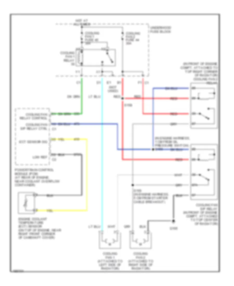
Электросхема системы охлаждения для Saturn Ion Red Line 2004
Электросхема системы охлаждения для Saturn Ion Red Line 2004 - Список элементов:
- (in engine harness, 1 cm from oil pressure switch) s160
- (in front of engine compt, attached to top right corner of radiator) cooling fan 2 relay
- (not used)
- 87a
- Cooling fan 1 (attached to left side of radiator)
- Cooling fan 1 fuse 45 30a
- Cooling fan 1 relay
- Cooling fan 2 (attached to right side of radiator)
- Cooling fan 2 fuse 44 30a
- Cooling fan relay control
- Cooling fan s/p relay (in front of engine compt, attached to top center of radiator)
- Cooling fan s/p relay ctrl
- Ect sensor sig
- Engine coolant temperature (ect) sensor (on top of engine, near right front corner of camshaft cover)
- F1 c1
- G105
- Hot at all times
- Low ref
- Powertrain control module (pcm) (at rear of engine, near coolant overflow container)
- Red
- S156 (in engine harness, 5 cm from starter cable breakout)
- S158
- Underhood fuse block
СИСТЕМА ПЕРЕДАЧИ ДАННЫХ
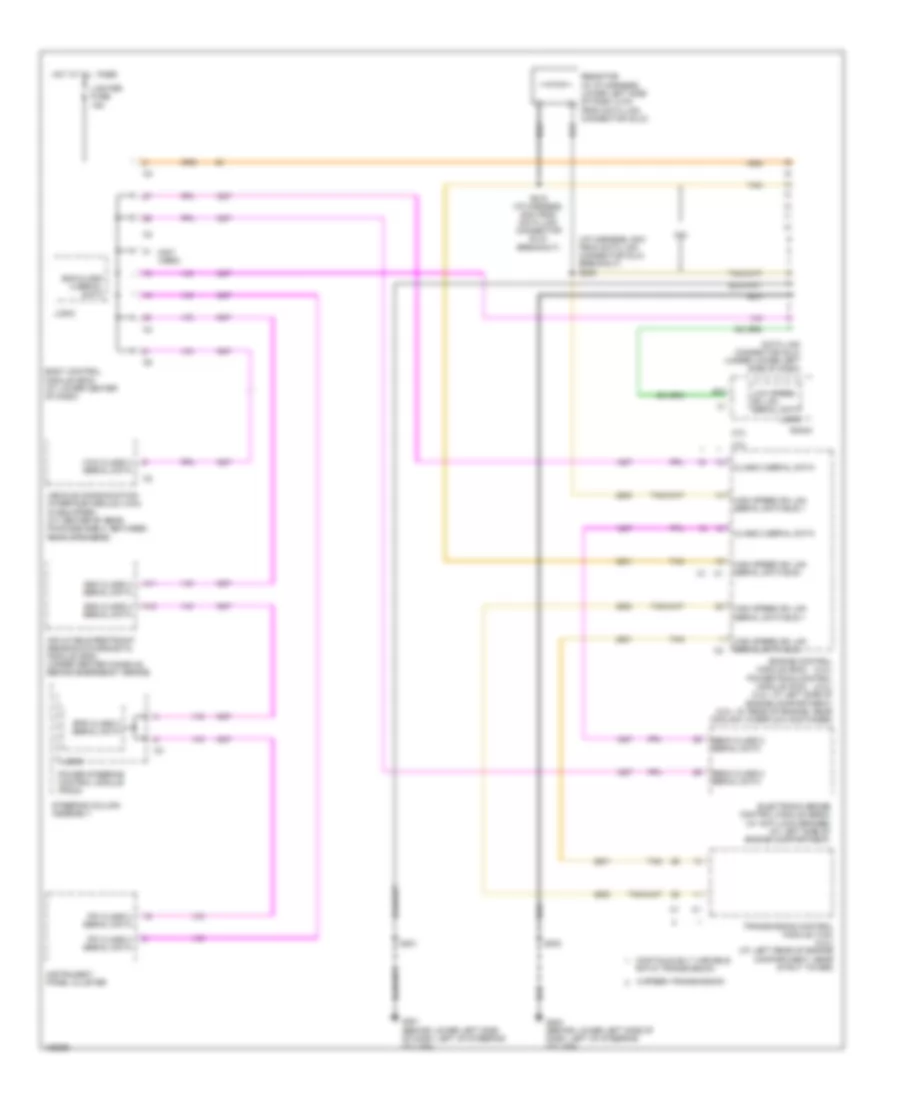
Электросхема линии передачи данных CAN для Saturn Ion Red Line 2004
Электросхема линии передачи данных CAN для Saturn Ion Red Line 2004 - Список элементов:
- (i/p harness, 5cm from data link connector (dlc) breakout) s205
- (not used)
- 2.0l
- 2.2l
- 5 speed transmission
- A11
- A12
- B10
- Bcm class 2 serial data
- Body control module (bcm) (at lower center of dash)
- Class 2 serial data
- Continuously variable ratio transmission
- Data link connector (dlc) (under lower left side of dash)
- Ebcm class 2 serial data
- Electronic brake control module (ebcm) (w/ anti-lock brakes) (at left side of engine compartment)
- Engine control (2.2l) powertrain control (2.0l) (2.2l: at left side of engine compartment) (2.0l: at rear of engine, near coolant overflow container)
- Eps class 2 serial data
- G201 (behind lower left side of dash, left of steering column)
- G203 (behind lower left side of dash, left of steering column)
- High speed gm lan serial data bus +
- High speed gm lan serial data bus -
- Hot at all times
- Inflatable restraint sensing & diagnostic module (sdm) (under center console, behind emergency brake)
- Instrument panel cluster
- Ipc class 2 serial data
- Lighter fuse 15a
- Logic
- Low speed gm lan serial data
- Module (ecm)
- Module (pcm)
- Power steering control module (pscm)
- Radio
- Resistor (in i/p harness, lower left side of dash, 6 cm from data link connector (dlc))
- S215 (i/p harness, 6cm from data link connector (dlc) breakout)
- S221
- S233
- Sdm class 2 serial data
- Steering column assembly
- Tan
- Transmission control module (tcm) (2.2l) (at left rear of engine compartment, near strut tower)
- Vcim class 2 serial data
- Vehicle communication interface module (vcim) (if equipped) (at center of rear package shelf, between rear speakers)
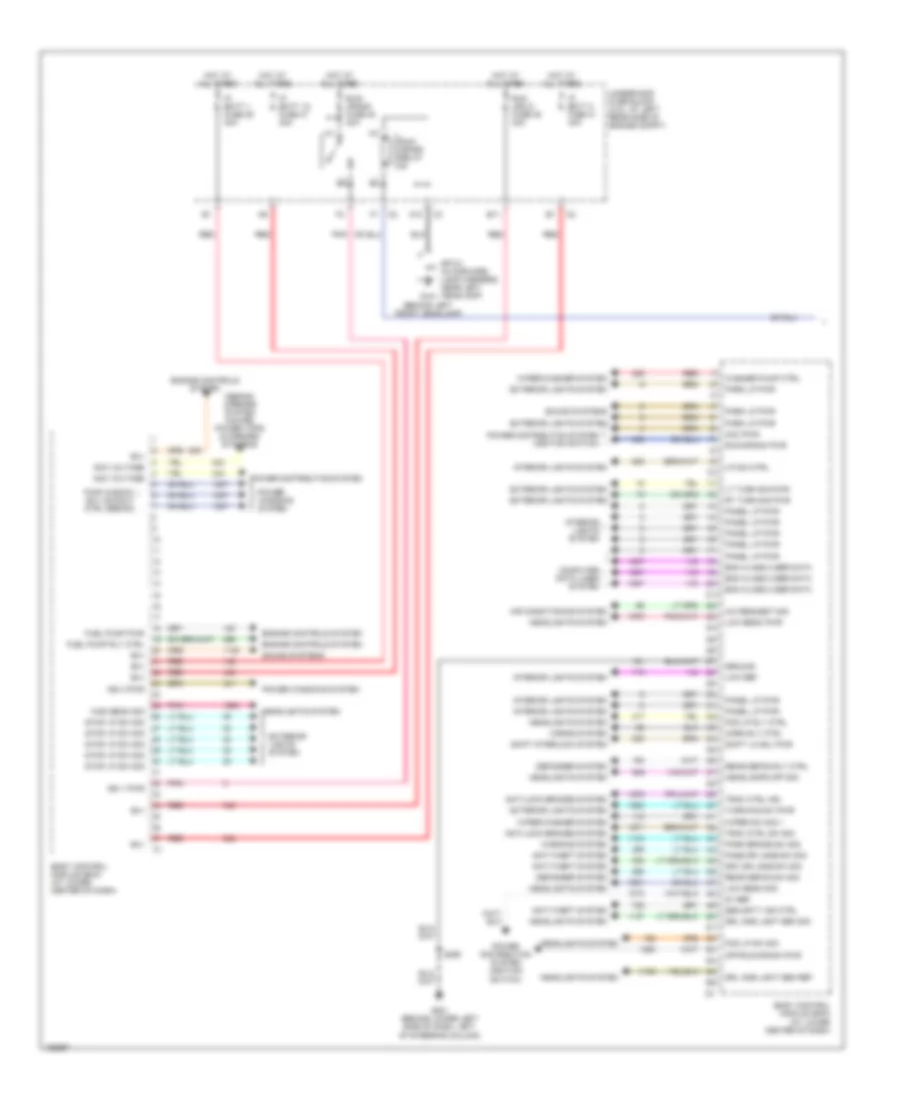
СИСТЕМА УПРАВЛЕНИЯ ДВИГАТЕЛЯ
2.0L
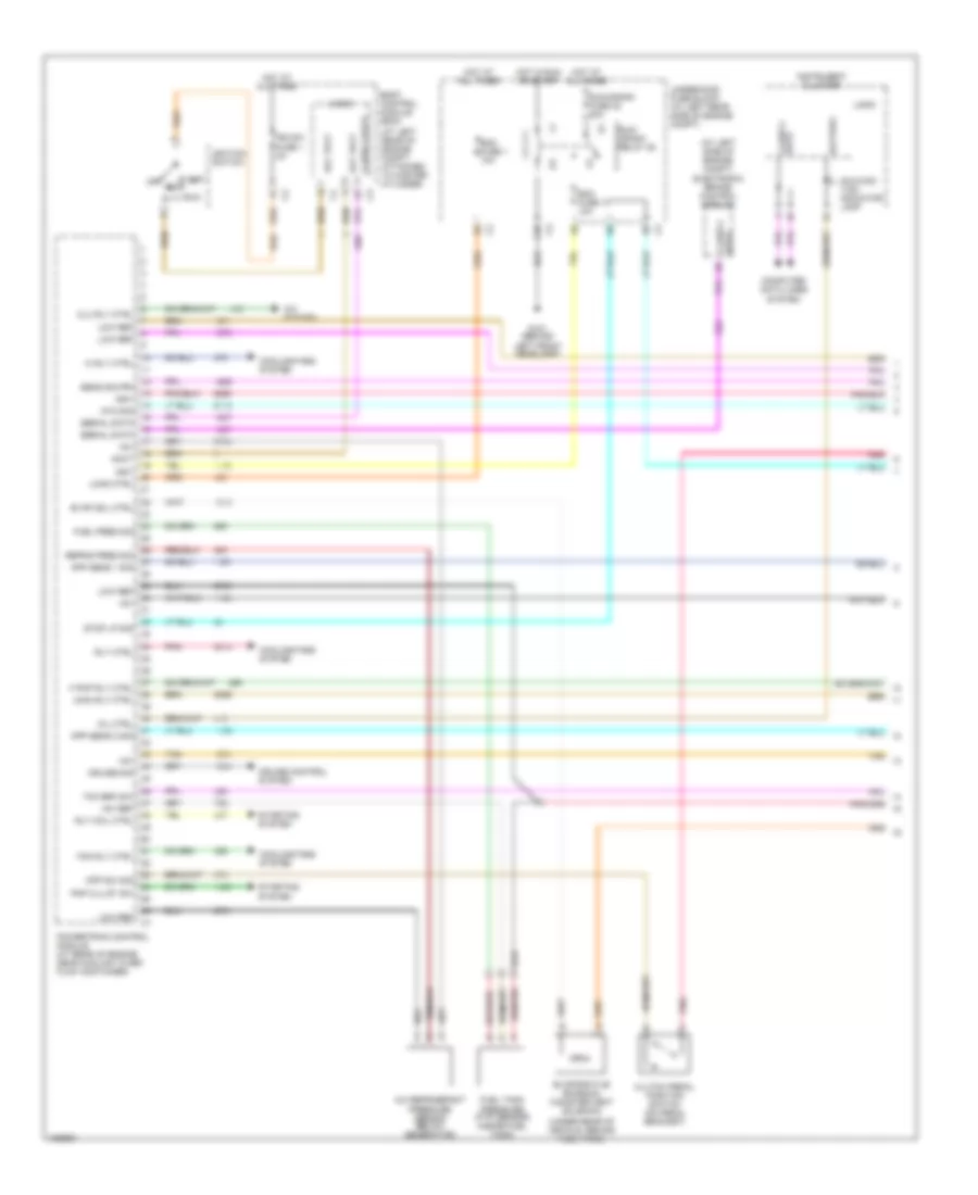
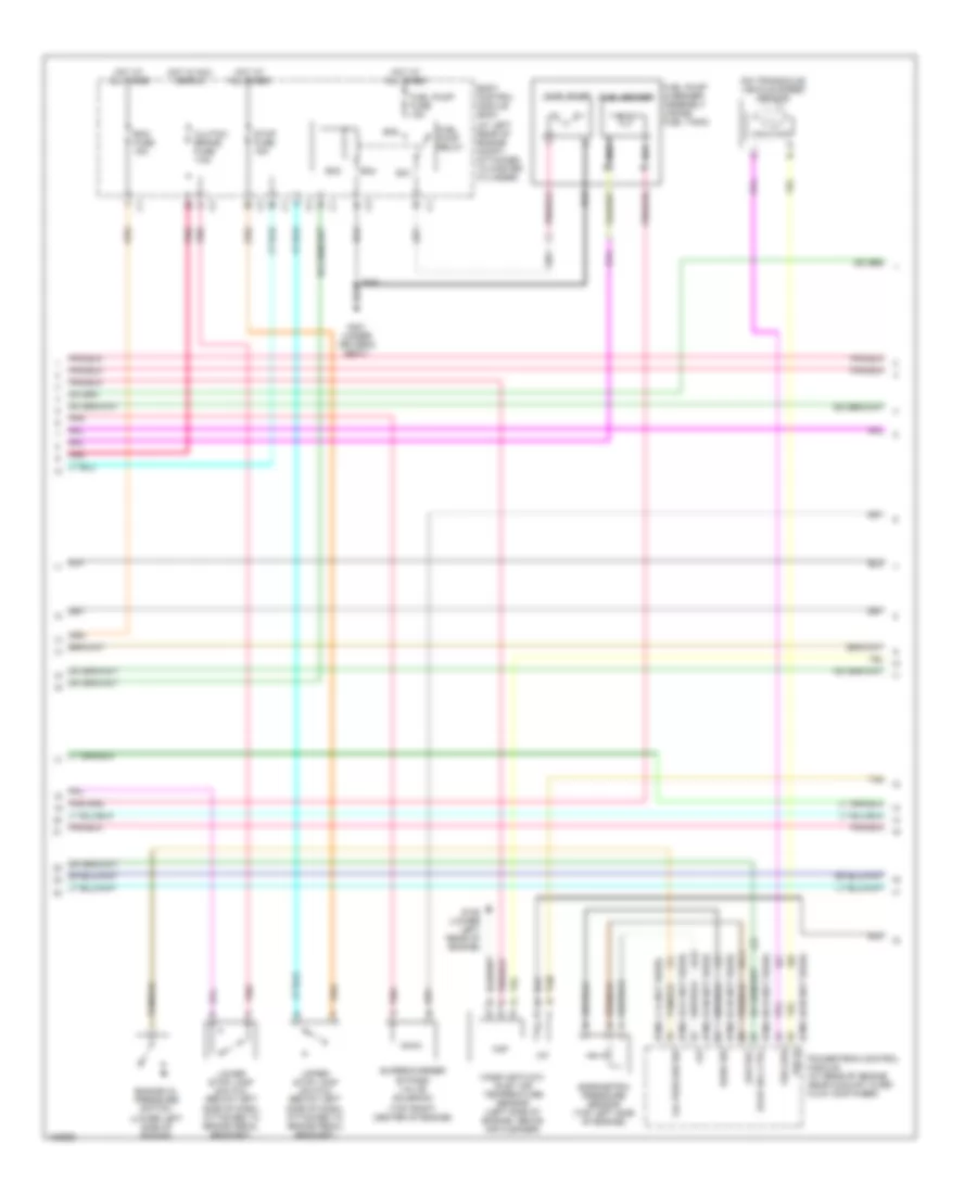
2.0L, Электросхема системы управления двигателем (1 из 4) для Saturn Ion Red Line 2004
2.0L, Электросхема системы управления двигателем (1 из 4) для Saturn Ion Red Line 2004 - Список элементов:
- (at left rear of engine compt, attached to master cylinder)
- (at left side of engine compt) electronic brake control module
- (under rear of vehicle, behind fuel tank)
- +5v
- +5v ref
- A/c refrigerant pressure sensor (below generator)
- A/c system
- A10
- Acc
- Acc volt
- Accy
- App sens 1 sig
- App sens 2 sig
- Battery
- Body control module (bcm)
- Class 2 data
- Clu rly ctrl
- Clutch pedal position switch (on pedal bracket)
- Computer data lines system
- Cooling fans system
- Cpp sw sig
- Cruise control system
- Cruise sig
- Data class 2
- Ecm fuse 1 10a
- Ecm fuse 13 10a
- Evap sol ctrl
- Evaporative emission canister vent solenoid
- F pmp rly ctrl
- Fan rly ctrl
- Fuel pres sig
- Fuel tank pressure (ftp) sensor (inside fuel tank)
- G101 (behind left front headlamp)
- Hi rly ctrl
- Hot at all times
- Hot in run or start
- Iat2 sig
- Ign sw fuse 1 2a
- Ign1
- Ignition switch
- Instrument cluster
- Load ctrl
- Logic
- Low ref
- Main rly ctrl
- Malfunc- tion indicator lamp
- Mil ctrl
- Off
- Pnk
- Pnp clu st sw
- Powertrain control module (at rear of engine near coolant over- flow container)
- Red/pnk
- Refrig pres sig
- Rly coil ctrl
- Rly ctrl
- Run
- Run/ crank relay 28
- Run/crank fuse 38 30a
- Sens sig pri
- Serial data
- Start
- Starting system
- Stop lp sig
- Tan
- Tcc brk sw
- Underhood fuse block (at left rear side of engine compt)
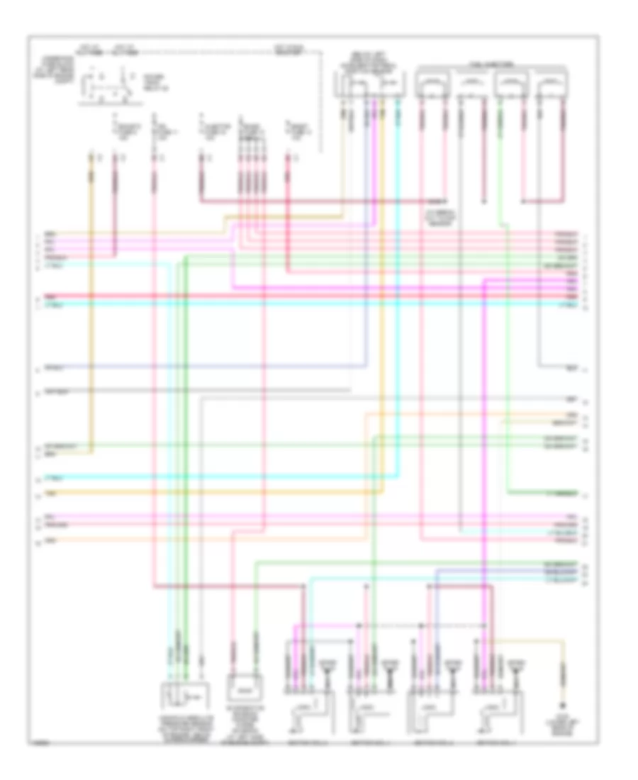
2.0L, Электросхема системы управления двигателем (2 из 4) для Saturn Ion Red Line 2004
2.0L, Электросхема системы управления двигателем (2 из 4) для Saturn Ion Red Line 2004 - Список элементов:
- (at break- out to map sensor)
- (below left side of dash) accelerator pedal position sensor
- Boost fuse 14 10a
- Ecm/etc fuse 9 15a
- Emiss fuse 10 15a
- Evaporative emission canister purge solenoid (at left side of engine compt)
- Fuel injectors
- G105 (lower left rear of engine)
- Hot at all times
- Hot in run or start
- Ign fuse 11 10a
- Ignition coil 1
- Ignition coil 2
- Ignition coil 3
- Ignition coil 4
- Injector fuse 16 10a
- Logic
- Manifold absolute pressure sensor (on top right front of engine, above supercharger)
- Nca
- Pnk
- Power- train relay 28
- S139
- Spark plug
- Tan
- Underhood fuse block (at left rear side of engine compt)
2.0L, Электросхема системы управления двигателем (3 из 4) для Saturn Ion Red Line 2004
2.0L, Электросхема системы управления двигателем (3 из 4) для Saturn Ion Red Line 2004 - Список элементов:
- (at left rear of engine compt, attached to master cylinder)
- (on transaxle) vehicle speed sensor
- (pins 1-14 not used)
- (pins 16-21 not used)
- (pins 23-30 not used)
- (pins 32-35 not used)
- (pins 38-43 not used)
- (pins 46-56 not used)
- (top front center of engine)
- +5v
- Ba1
- Ba2
- Ba3
- Ba4
- Baro sig
- Barometric pressure sensor (top left side of engine)
- Bcm fuse 15a
- Body control module (bcm)
- Clutch/ brake fuse 7.5a
- Engine oil pressure switch (lower left side of engine)
- Evap sol ctrl
- Fuel pump
- Fuel pump & sender assembly (inside fuel tank)
- Fuel pump fuse 15a
- Fuel pump relay
- Fuel sender
- G105 (lower left rear of engine)
- G301 (under driver's seat)
- Hot at all times
- Hot in acc or run
- Iat
- Low ref
- Lower stop lamp switch (below left side of dash, attached to brake pedal bracket)
- Maf
- Mass air flow/ inlet air temperature sensor (left side of engine, above air cleaner)
- Nca
- Oil pres sw sig
- Pnk
- Powertrain control module (at rear of engine near coolant over- flow container)
- S351
- Stop fuse 15a
- Supercharger bypass valve solenoid
- Tan
- Upper stop lamp switch (below left side of dash, attached to brake pedal bracket)
- Vss hi
- Vss low
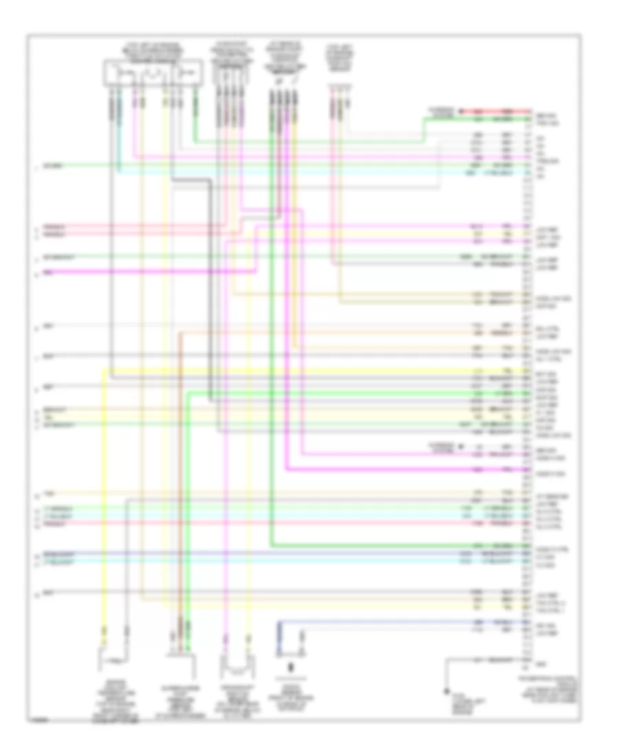
2.0L, Электросхема системы управления двигателем (4 из 4) для Saturn Ion Red Line 2004
2.0L, Электросхема системы управления двигателем (4 из 4) для Saturn Ion Red Line 2004 - Список элементов:
- (at rear of engine compt, in exhaust manifold) heated oxygen sensor 1
- (in exhaust near catalytic converter) heated oxygen sensor 2
- (top left of engine) camshaft position sensor
- (top left of engine, below supercharger) throttle actuator control module
- +5v
- A tan
- Charging system
- Ckp 1 sig
- Cmp sig
- Crankshaft position sensor (on lower rear of engine, below oil filter)
- Ect sig
- Engine coolant temperature sensor (top of engine, near right front corner of camshaft cover)
- G105 (lower left rear of engine)
- Gen sig
- Gnd
- Ho2s hi ctrl
- Ho2s hi sig
- Ho2s low sig
- Iat sens sig
- Ic 1 sig
- Ic 2 sig
- Ic 3 sig
- Ic4 sig
- Inj 1 ctrl
- Inj 2 ctrl
- Inj 3 ctrl
- Inj 4 ctrl
- Knock sensor (front of engine, in front of dip stick)
- Ks1 sig
- Low ref
- Maf sig
- Map sig
- Nca
- Powertrain control module (at rear of engine near coolant over- flow container)
- Red
- Scip sig
- Sol ctrl
- Supercharge inlet pressure sensor (top left of supercharger)
- Tac ctrl 1
- Tac ctrl 2
- Tan
- Tps1 sig
- Tps2 sig
СИСТЕМА УСИЛИТЕЛЯ РУЛЯ
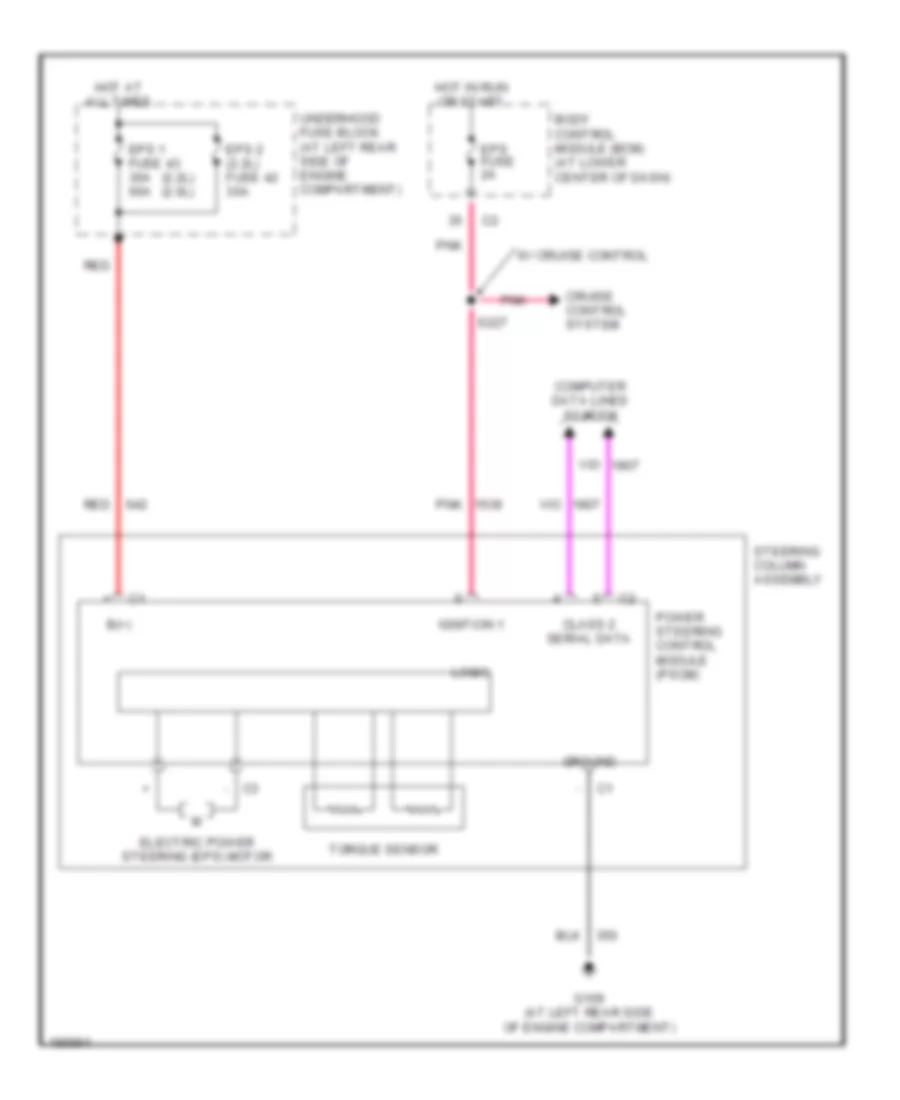
Электросхема усилителя руля для Saturn Ion Red Line 2004
Электросхема усилителя руля для Saturn Ion Red Line 2004 - Список элементов:
- (2.2l) (2.0l)
- - c3
- B(+)
- Body control module (bcm) (at lower center of dash)
- Class 2 serial data
- Computer data lines system
- Cruise control system
- Electric power steering (eps) motor
- Eps 1 fuse 43 30a 60a
- Eps 2 (2.2l) fuse 42 30a
- Eps fuse 2a
- G109 (at left rear side of engine compartment)
- Ground
- Hot at all times
- Hot in run or start
- Ignition 1
- Logic
- Pnk
- Power steering control module (pscm)
- Red
- S227
- Steering column assembly
- Torque sensor
- Underhood fuse block (at left rear side of engine compartment)
- W/ cruise control
Система Фар
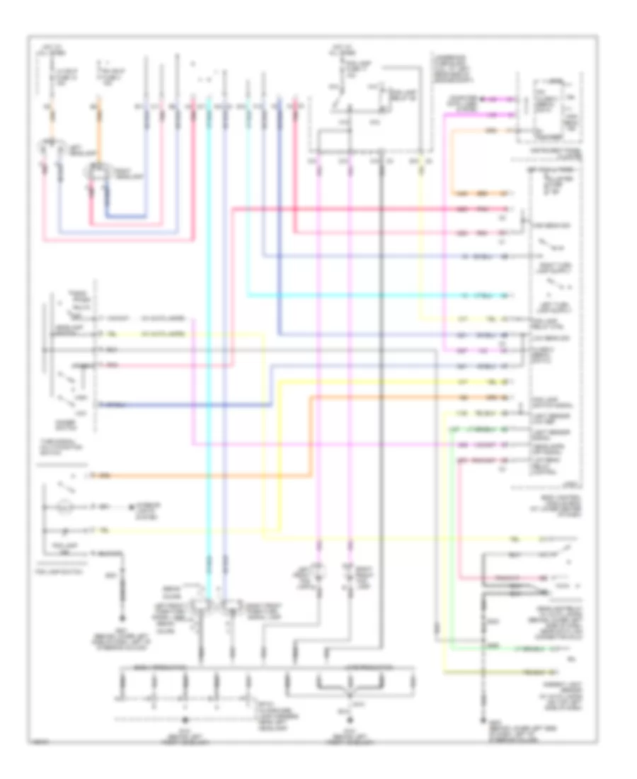
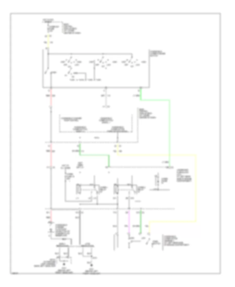
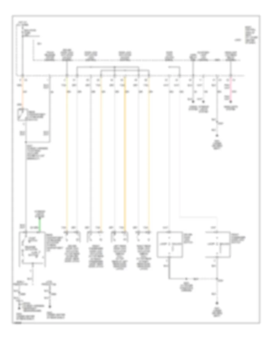
Электросхема фар и противотуманок для Saturn Ion Red Line 2004
Электросхема фар и противотуманок для Saturn Ion Red Line 2004 - Список элементов:
- (w/ auto lamps)
- A10
- Ambient light sensor (w/ auto lamps) (on top left side of dash)
- Auto
- B+ voltage
- B11
- Body control module (bcm) (at lower center of dash)
- C pnk
- C11
- C12
- C2 f4
- C3 a12
- Class 2 serial data 2
- Cluster fuse 7.5a
- Computer data lines system
- Coupe
- D11
- D12
- Dimmer switch
- E10
- E12
- Early production
- F12
- Flash
- Fog lamp fuse 17 10a
- Fog lamp ind
- Fog lamp relay 26
- Fog lamp relay ctrl
- Fog lamp switch
- Fog lamp switch signal
- G10
- G101 (behind left front headlamp)
- G12
- G201 (behind lower left side of dash, left of steering column)
- G203 (behind lower left side of dash, left of steering column)
- H10
- H12
- Head
- Headlamp relay (w/ auto lamps) (behind lower left side of dash, near data link connector (dlc))
- Headlamp switch
- Headlamps off signal
- High
- High beam ind
- High beam sig
- Hot at all times
- Instrument panel cluster
- Interior lights system
- Ipc class 2 serial data
- Late production
- Left front fog lamp b
- Left front park/turn signal lamp
- Left headlamp
- Lh hdlp fuse 18 15a
- Light sensor low ref
- Light sensor signal
- Logic
- Low
- Low beam relay control
- Low beam sig
- Off
- Park
- Pnk
- Rh hdlp fuse 4 15a
- Right front fog lamp
- Right front park/turn signal lamp
- Right headlamp
- S101
- S221
- S233
- S260
- Sedan
- Sp101 (in forward lamp harness, near left headlamp)
- Turn signal/ multi-function switch
- Underhood fuse block (2.2l: at left rear side of engine compt)
Стартер Генератор
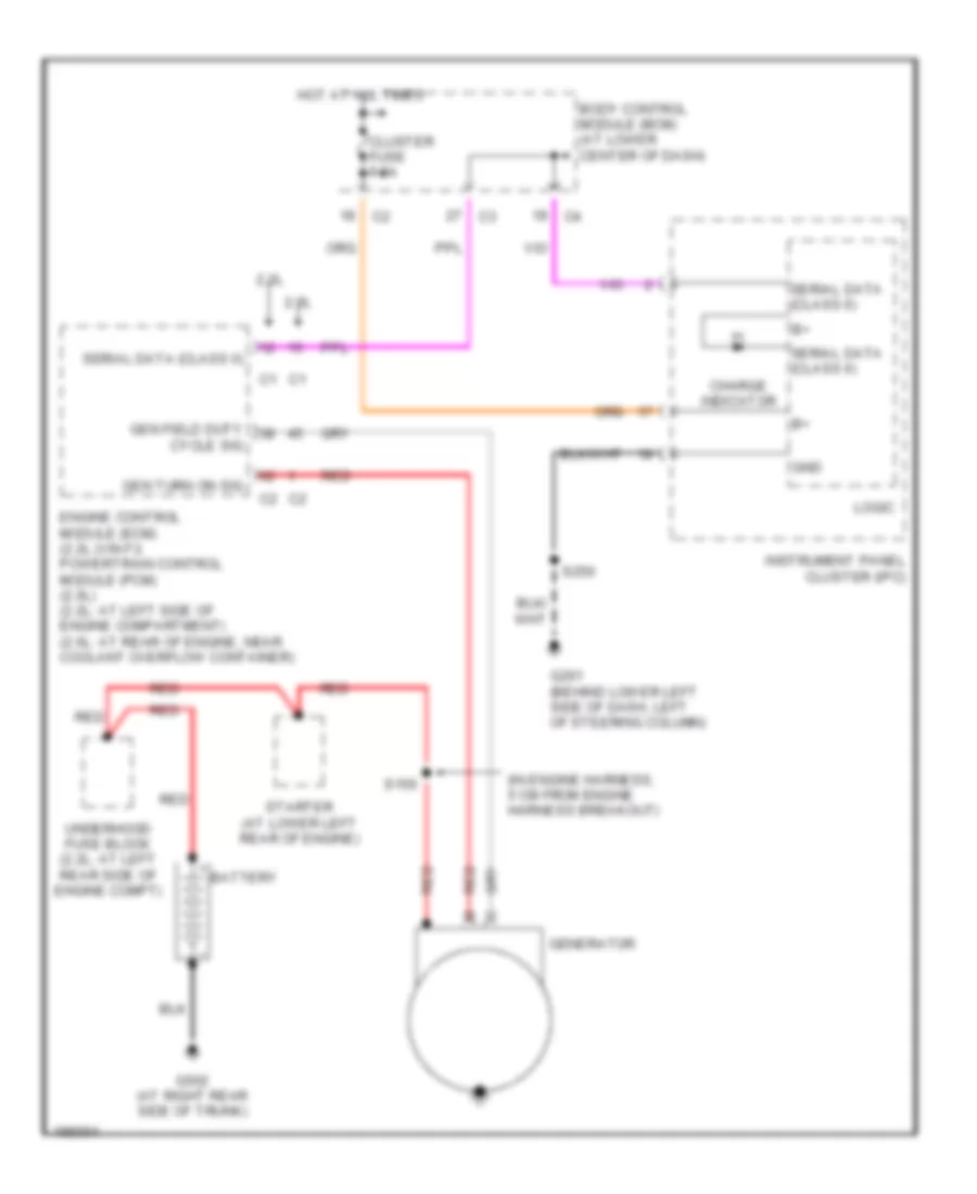
Электросхема Генератора для Saturn Ion Red Line 2004
Электросхема Генератора для Saturn Ion Red Line 2004 - Список элементов:
- (in engine harness, 5 cm from engine harness breakout)
- 2.0l
- 2.2l
- Battery
- Body control module (bcm) (at lower center of dash)
- Charge indicator
- Cluster fuse 7.5a
- Cycle sig
- Engine control module (ecm) (2.2l (vin f)) powertrain control module (pcm) (2.0l) (2.2l: at left side of engine compartment) (2.0l: at rear of engine, near coolant overflow container)
- G201 (behind lower left side of dash, left of steering column)
- G502 (at right rear side of trunk)
- Gen field duty
- Gen turn on sig
- Generator
- Gnd
- Hot at all times
- Instrument panel cluster (ipc)
- Logic
- Red
- S150
- S250
- Serial data (class ii)
- Starter (at lower left rear of engine)
- Underhood fuse block (2.2l: at left rear side of engine compt)
Электросхема стартера для Saturn Ion Red Line 2004
Электросхема стартера для Saturn Ion Red Line 2004 - Список элементов:
- 5v ref
- Acc
- Armature m
- B10
- Battery
- Bcm class 2 serial data
- Body control module (bcm) (at lower center of dash)
- Charging circuit
- Clutch start switch (below left side of dash, on clutch pedal bracket)
- Clutch start switch signal
- Clutch/ brake fuse 7.5a
- Crank fuse 46 30a
- Ecm class 2 serial data
- G502 (at right rear side of trunk)
- Hold-in windings
- Hot in acc or run
- Ignition switch
- Lock
- Logic
- Off
- Off/run/crank voltage
- Pcm cont relay 31
- Pnk
- Powertrain control module (pcm) (at rear of engine, near coolant overflow container)
- Pull-in windings
- Red
- Run
- Start
- Starter
- Starter relay coil control
- Underhood fuse block
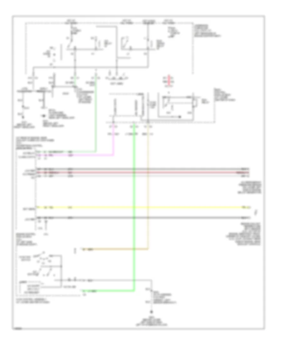
Стеклоочистители и Стеклоомыватели Дворники
Электросхема стеклоочистителя, дворников и омывателя для Saturn Ion Red Line 2004
Электросхема стеклоочистителя, дворников и омывателя для Saturn Ion Red Line 2004 - Список элементов:
- (not used)
- A10 c3
- B11
- Body control module (bcm) (at lower center of dash)
- D10 c2
- Early production
- F10
- F11
- G101 (behind left front headlamp)
- High
- Hot at all times
- Hot in acc or run
- Int
- L10
- L11
- Late production
- Low
- M11
- Mist
- Off
- Park switch
- Q10
- Q11
- R11
- Red
- S101
- Sp101 (in forward lamp harness, near left headlamp)
- Underhood fuse block (2.2l) at left rear side of engine compartment)
- Wash
- Windshield washer fluid pump (on bottom of washer fluid reservoir)
- Windshield washer pump control
- Windshield wiper motor assembly (at left rear side of engine compartment)
- Windshield wiper motor park switch signal
- Windshield wiper switch signal 1
- Windshield wiper switch signal 2
- Windshield wiper/washer switch
- Wiper 1 relay
- Wiper 2 relay
- Wiper diode
- Wiper fuse 19 25a
- Wiper sw fuse 10a
- X10
ЦЕНТРАЛЬНЫЙ ЗАМОК
Электросхема центрального замка для Saturn Ion Red Line 2004
Электросхема центрального замка для Saturn Ion Red Line 2004 - Список элементов:
- Ajar switch
- B(+)
- Bcm (pwr) fuse 15a
- Body control module (bcm) (at lower center of dash)
- Courtesy lamp low control
- Door lock actuator lock control
- Door lock actuator unlock control
- Door lock/ unlock signal
- Driver door lock actuator (in top rear of driver door, near door latch)
- Driver door lock actuator unlock control
- Driver door lock switch
- Early production
- Front passenger door lock actuator (in top rear of front passenger door, near door latch)
- Front passenger door lock switch
- G301 (under driver's seat)
- G403 (under center of rear shelf)
- Gnd
- Headlamp low beam relay control
- Headlights system
- Horn relay ctrl
- Horns system
- Hot at all times
- Interior lights system
- Late production
- Left rear door lock actuator (sedan) (2.2l) (in top rear of left rear door, near door latch)
- Lock
- Logic
- Rear compartment lid release actuator (in rear compartment lid)
- Rear compartment lid release switch
- Release actuator m
- Right rear door lock actuator (sedan) (2.2l) (in top rear of right rear door, near door latch)
- S337 (in body harness, 7.5 cm from auxiliary power outlet breakout)
- S351
- S533 (w/ power windows & mirrors)
- S990
- Sp403 (in body harness, near right rear speaker)
- Tan
- Trunk release motor control
- Unlock
- Valet switch

 Čeština
 Dansk
Dansk Deutsch
 English
 English
 Español
 Suomi
Suomi Français
 Français
 עברית
עברית Hrvatski
 Magyar
 Italiano
 日本語
日本語 한국어
한국어 Nederlands
 Polski
 Português
 Português
 Română
 Русский
 Slovenčina
 Slovenščina
 Svenska
 Türkçe
 中文 (中国)