ELECTRONIC POWER STEERING
Electronic Power Steering Wiring Diagram for Honda Accord Touring 2013
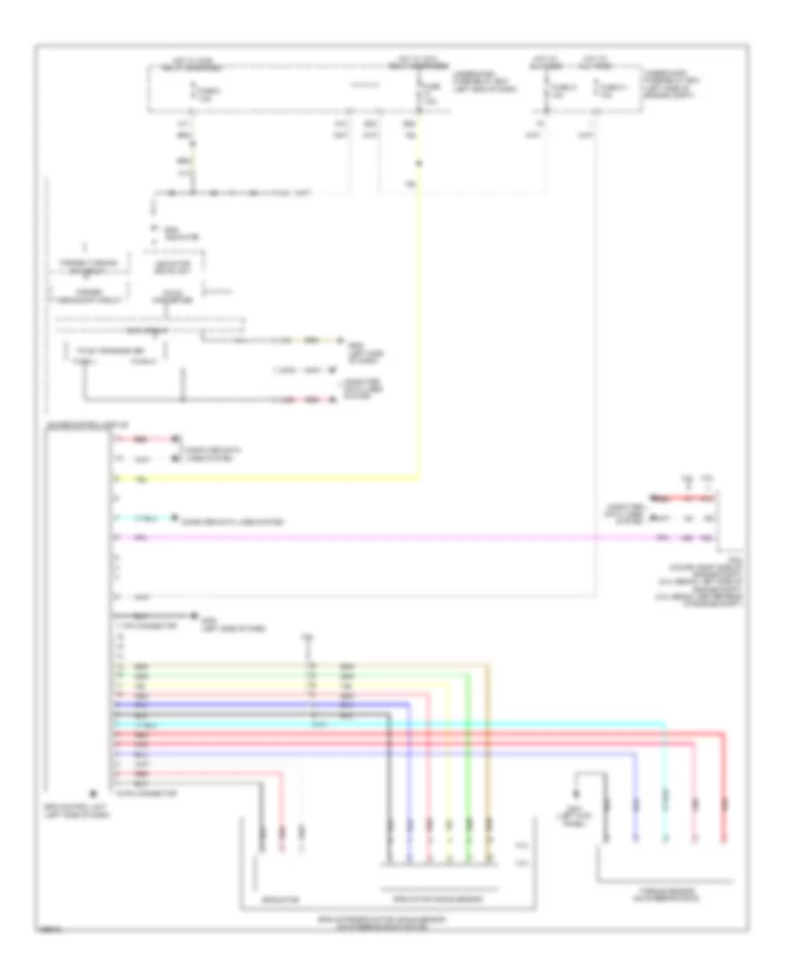
List of elements for Electronic Power Steering Wiring Diagram for Honda Accord Touring 2013:
- 11 pin connector
- 16 pin connector
- 2.4l
- 3.5l
- A10
- A17
- A19
- A20
- A26
- A30
- C131
- Computer data lines system
- Dc-dc converter
- E23
- E26
- Eps control unit (left side of dash)
- Eps indicator
- Eps motor
- Eps motor angle sensor
- Eps motor/eps motor angle sensor (on steering rack motor)
- F-can h
- F-can l
- F-can transceiver
- Forced turning-
- Forced turning-off circuit
- Fuse 2-1 70a
- Fuse 21 10a
- Fuse 5 7.5a
- Fuse 7.5a
- G401 (left kick panel)
- G402 (left side of dash)
- G502 (left side of dash)
- Gauge control module
- Hot at all times
- Hot w/ ig1a relay energized
- Hot w/ ig1b relay energized
- Indicator drive unit
- M11
- M12
- Main circuit
- On circuit
- Pcm (coupe: right side of engine compt) (2.4l sedan: left side of engine compt) (3.5l sedan: center rear of engine compt)
- Pnk
- Red
- Torque sensor (on steering rack)
- Under-dash fuse/relay box (left end of dash)
- Under-hood fuse/relay box (left side of engine compt)
 English