ANTI-THEFT
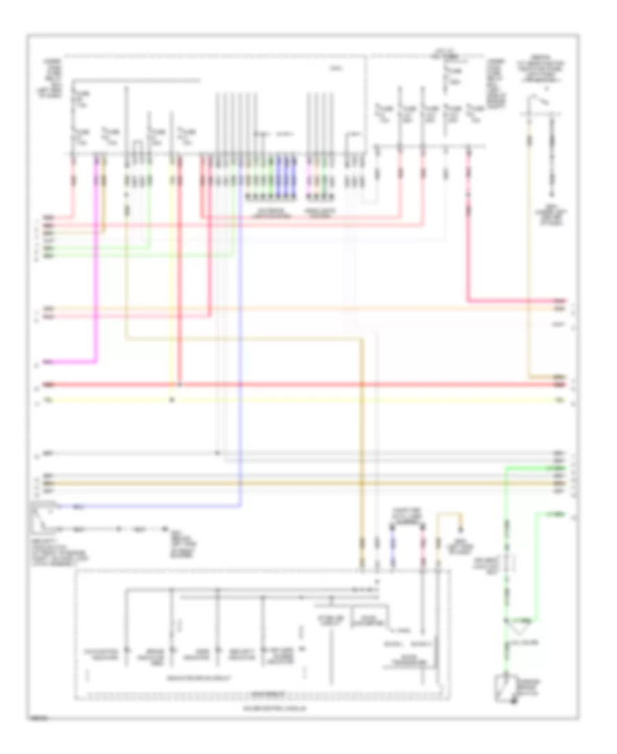
Forced Entry Wiring Diagram (1 of 6) for Honda Accord Touring 2013

List of elements for Forced Entry Wiring Diagram (1 of 6) for Honda Accord Touring 2013:
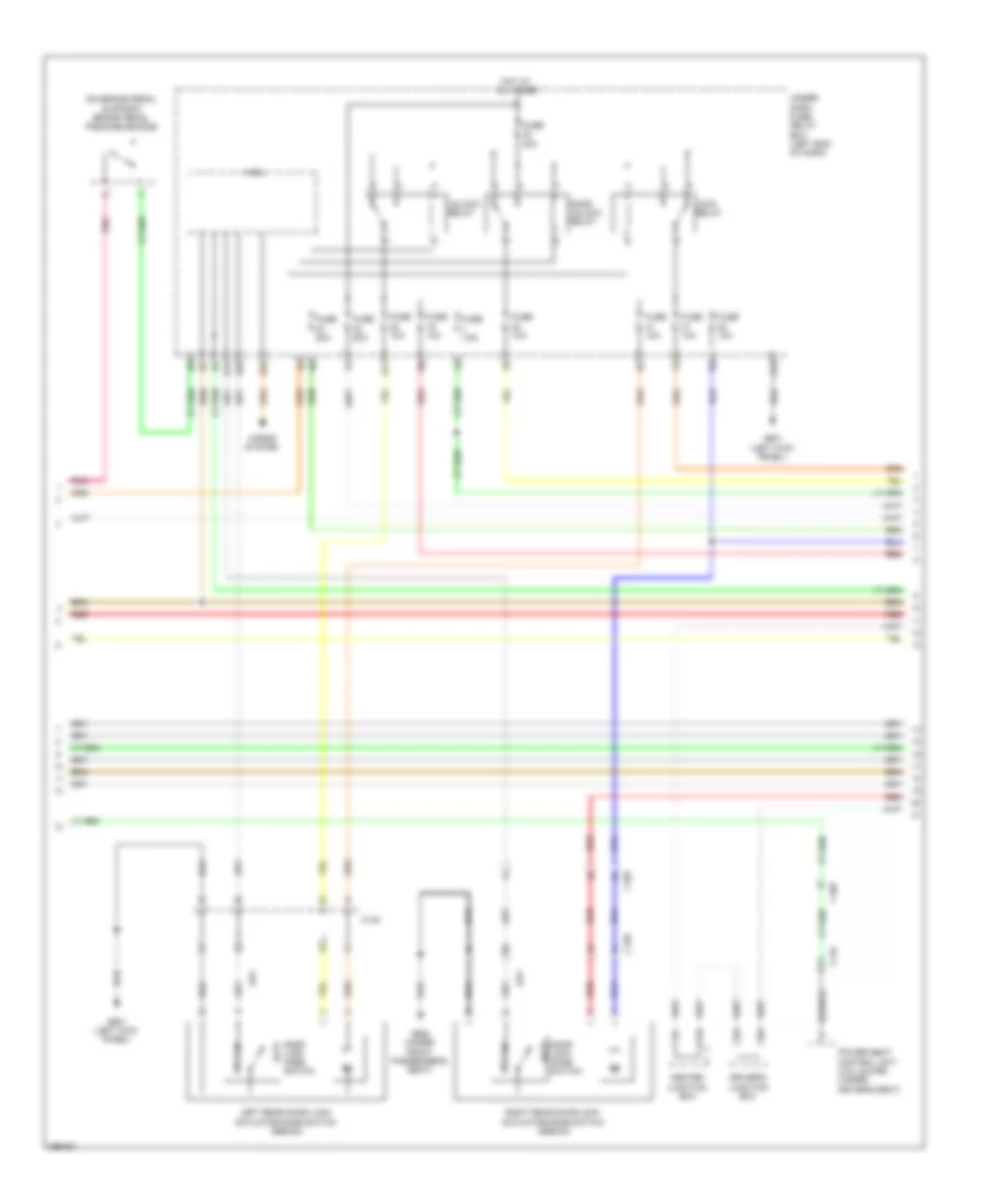
Forced Entry Wiring Diagram (2 of 6) for Honda Accord Touring 2013
List of elements for Forced Entry Wiring Diagram (2 of 6) for Honda Accord Touring 2013:
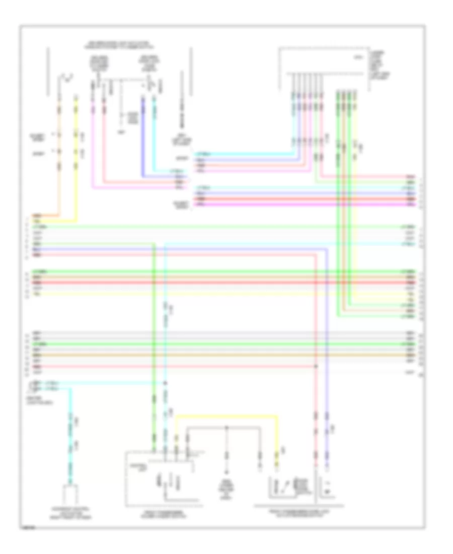
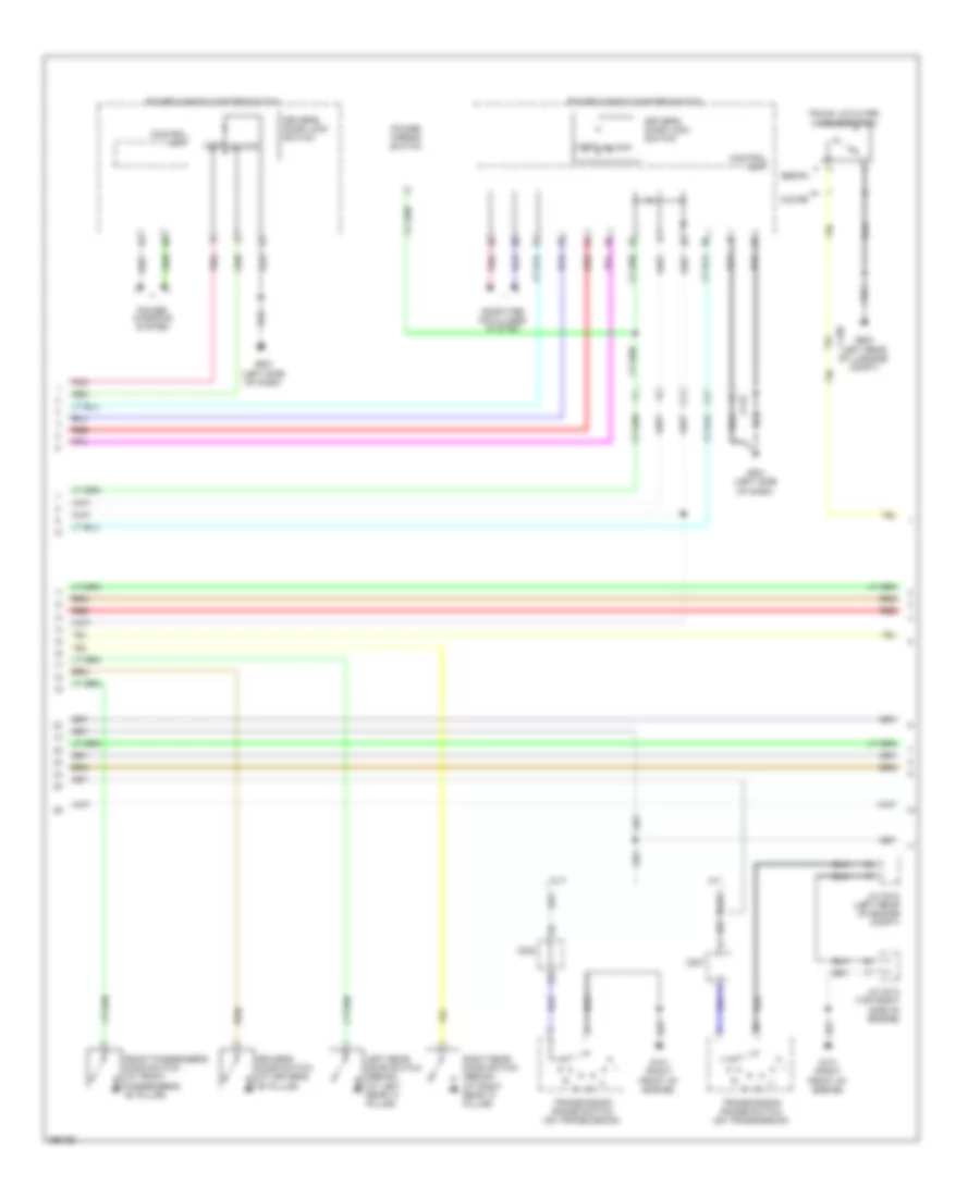
Forced Entry Wiring Diagram (3 of 6) for Honda Accord Touring 2013
List of elements for Forced Entry Wiring Diagram (3 of 6) for Honda Accord Touring 2013:
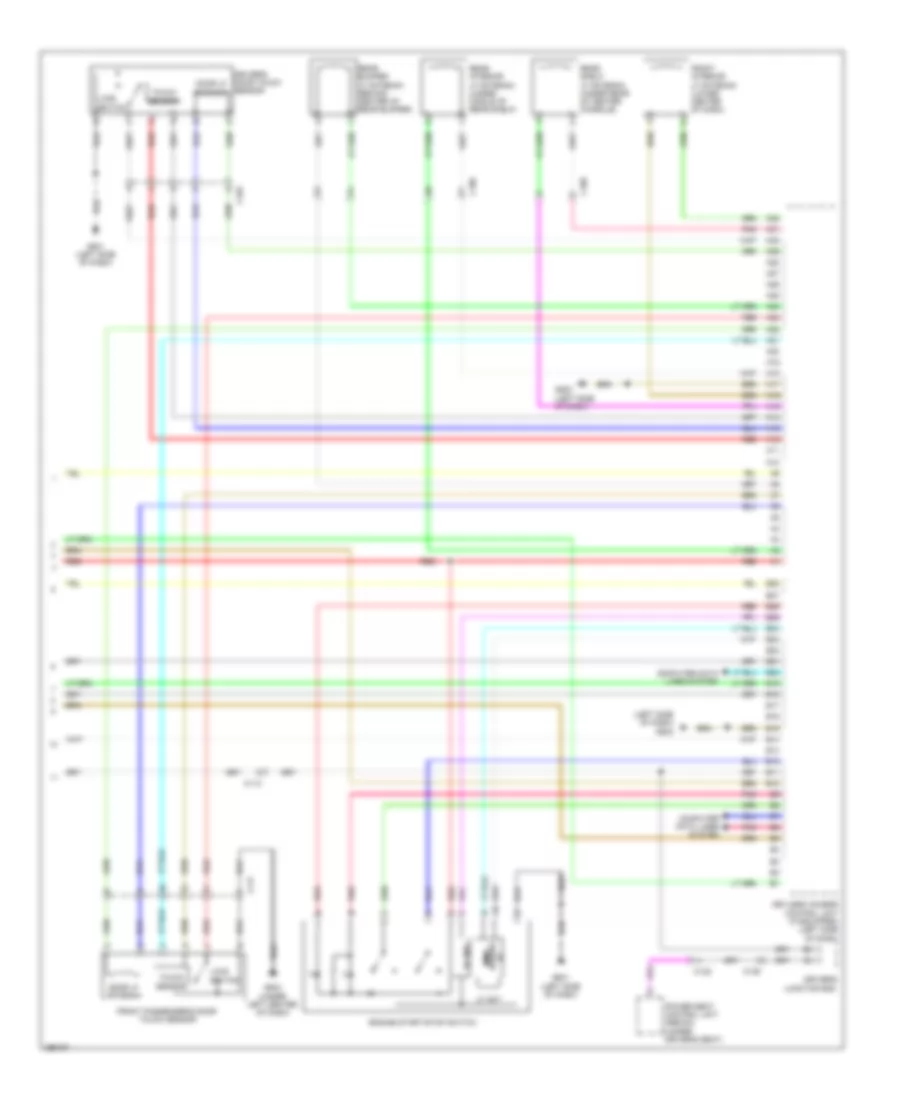
Forced Entry Wiring Diagram (4 of 6) for Honda Accord Touring 2013
List of elements for Forced Entry Wiring Diagram (4 of 6) for Honda Accord Touring 2013:
Forced Entry Wiring Diagram (5 of 6) for Honda Accord Touring 2013
List of elements for Forced Entry Wiring Diagram (5 of 6) for Honda Accord Touring 2013:
Forced Entry Wiring Diagram (6 of 6) for Honda Accord Touring 2013
List of elements for Forced Entry Wiring Diagram (6 of 6) for Honda Accord Touring 2013:
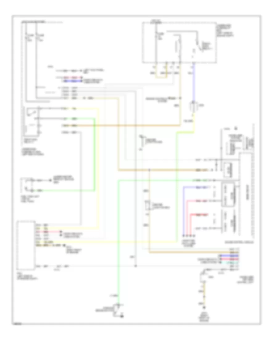
Immobilizer Wiring Diagram for Honda Accord Touring 2013
List of elements for Immobilizer Wiring Diagram for Honda Accord Touring 2013: