SHIFT INTERLOCKS
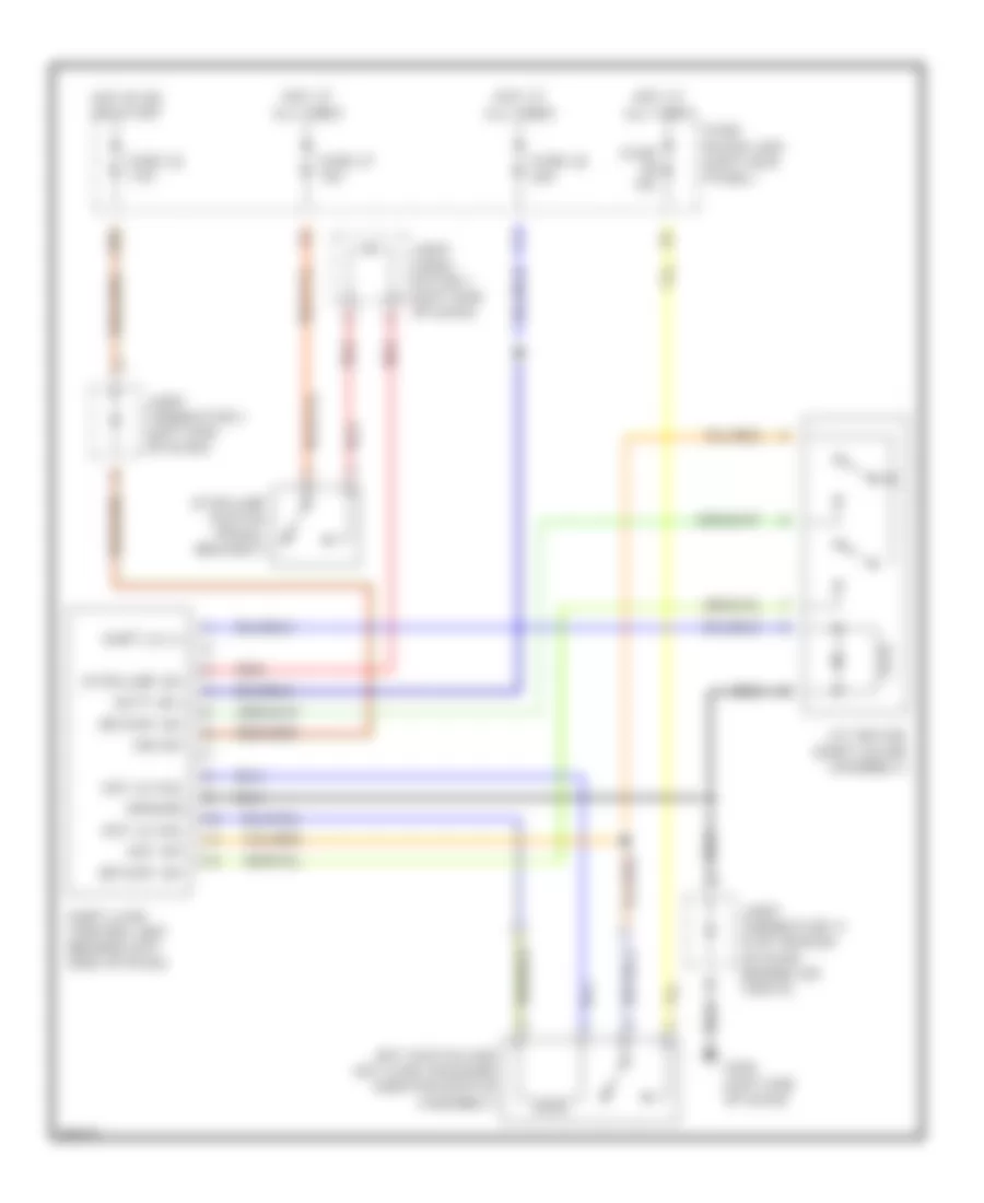
Shift Interlock Wiring Diagram for Infiniti Q45 1997
List of elements for Shift Interlock Wiring Diagram for Infiniti Q45 1997:
- 18b
- A/t device (shift lever assembly)
- Batt (b+)
- Detent sw
- Fuse 10a
- Fuse 26 20a
- Fuse 32 7.5a
- Fuse 37 15a
- Fuse block (j/b) (left kick panel)
- G202 (left end of dash)
- Ground
- Hot at all times
- Hot in on or start
- Ign sw
- Joint conn- ector 1 (left end of dash)
- Joint connector 11 (top center of dash, behind air vents)
- Joint connector 3 (left end of dash)
- Key lk sol
- Key sw
- Key switch and key lock solenoid (ignition switch assembly)
- Red
- Shift lk (+)
- Shift lock control unit (behind left side of dash)
- Stoplamp sw
- Stoplamp switch (pedal bracket)
 Čeština
 Dansk
Dansk Deutsch
 Ελληνικά
 English
 Español
 Suomi
Suomi Français
 Français
 עברית
עברית Hrvatski
 Magyar
 Italiano
 日本語
日本語 한국어
한국어 Nederlands
 Polski
 Português
 Português
 Română
 Русский
 Slovenčina
 Slovenščina
 Svenska
 Türkçe
 中文 (中国)
 English