СИСТЕМА УПРАВЛЕНИЯ ДВИГАТЕЛЯ
2.3L
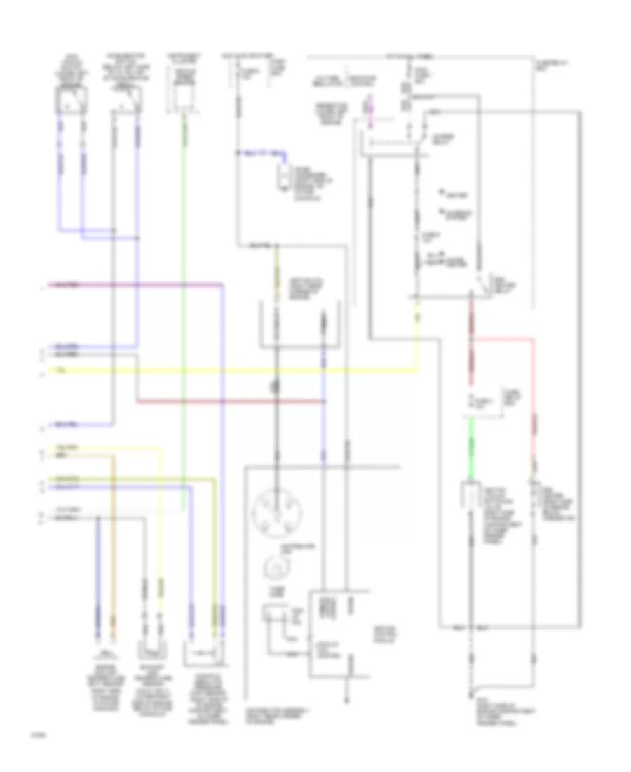
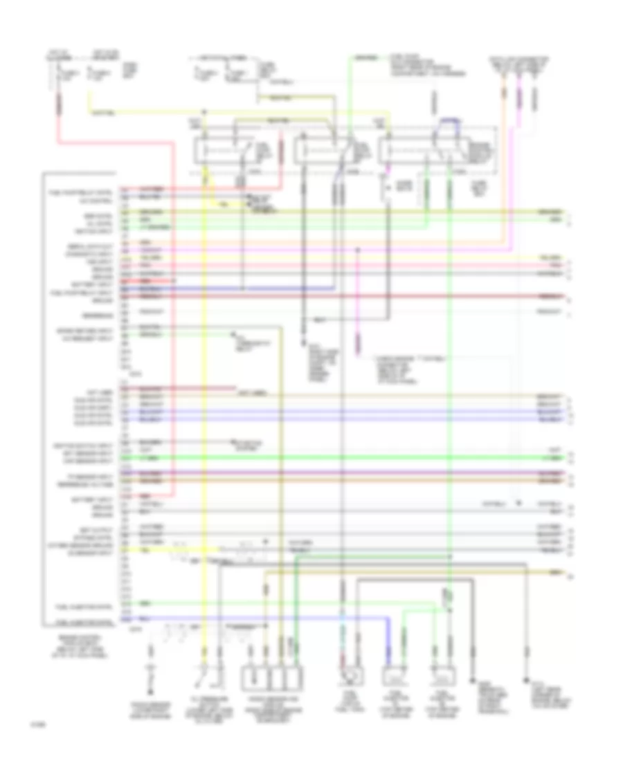
2.3L, Электросхема системы управления двигателя (1 из 2) для Isuzu Pickup S 1994
 https://portal-diagnostov.com/license.html
Automotive Electricians Portal FZCO
Automotive Electricians Portal FZCO
https://portal-diagnostov.com/license.html
https://portal-diagnostov.com/license.html
Automotive Electricians Portal FZCO
Automotive Electricians Portal FZCO
2.3L, Электросхема системы управления двигателя (1 из 2) для Isuzu Pickup S 1994 - Список элементов:
- "check engine" malfuction indicator lamp (mil)
- (below left side of i/p, at kick panel)
- (left side of engine compartment on inner fender panel)
- (right side of engine compartment on inner fender panel)
- (top center of engine on rear of carburetor)
- A/c on input
- A/c: compressor control
- Air inj react vsv cont
- Air management valve(amv)
- All times
- C214
- Dash fuse box
- Data link connector (below left side of i/p, at kick panel)
- Diagnostic trouble code (dtc) terminal
- Dlc/dtc input
- Duty sol control
- Duty solenoid (top center of engine in front of carburetor)
- Dwell lead
- Ect sensor input
- Efe heater relay cont
- Egr vsv control
- Engine control module (ecm)
- Engine control module relay
- Engine rpm input
- Evap cnstr purge vsv
- Evaporative emission canister purge vacuum switching valve (right side of engine compartment on inner fender panel)
- Exhaust gas recirculation (egr) vacuum switching valve (calif only)
- Exhaust gas temp sen
- Fuse 1 10a
- Fuse 3 10a
- Fuse 7 10a
- Fuse 8 10a
- Fuse/ relay box
- G101 (right side of engine compartment on inner fender panel)
- G104 (left rear corner of engine compartment on inner fender panel)
- G120 (right side of engine, on intake manifold)
- Ground
- Hot at
- Hot in on or start
- Idle vacuum switch in
- Ignition input
- Instrument cluster
- Manifold absolute pressure (map) vacuum switching valve
- Map sensor input
- Map vsv control
- Mil control
- Oxygen sensor (lower left side of engine, in exhaust manifold)
- Oxygen sensor input
- Power input
- Ref voltage
- Slow cut sol control
- Slow cut solenoid
- Vss input
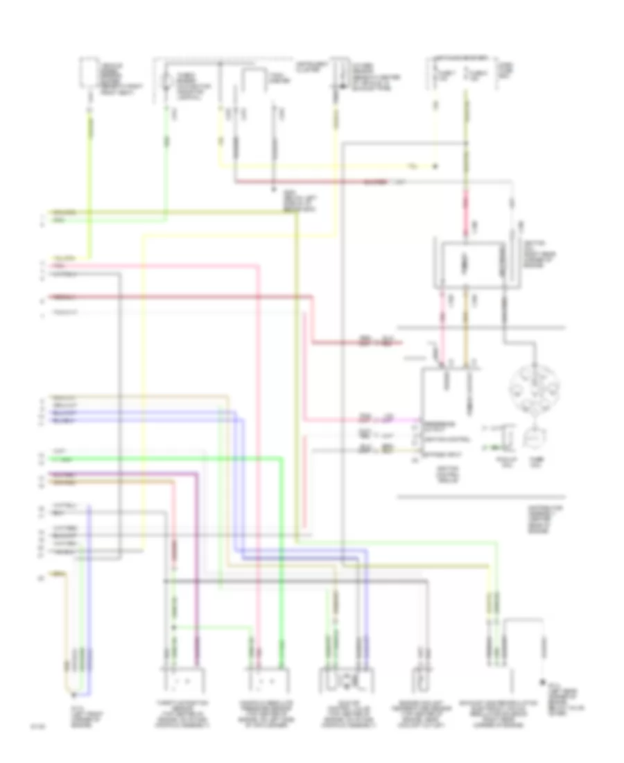
2.3L, Электросхема системы управления двигателя (2 из 2) для Isuzu Pickup S 1994
2.3L, Электросхема системы управления двигателя (2 из 2) для Isuzu Pickup S 1994 - Список элементов:
- (calif. only) (lower right side of engine, below intake manifold)
- (right side of engine, in intake manifold)
- Accelerator switch (below left side of i/p, on top of accelerator pedal)
- Charge relay
- Charging system
- Choke heater
- Dash fuse box
- Distributor assembly (right rear corner of engine)
- Distributor cap
- Efe heater (right side of engine, below caburetor)
- Efe heater relay
- Engine coolant temperature (ect) sensor
- Exhaust gas temperature sensor
- Fuse 2 10a
- Fuse 6 10a
- Fuse 9 15a
- Fuse/ relay box
- Fuse/relay box
- G101 (right side of engine compartment on inner fender panel)
- Generator (lower left front of engine)
- Ground
- Heater
- Hot at all times
- Hot in on or start
- Idle vacuum switch (lower left front of engine)
- Ignition coil (right rear corner of engine)
- Ignition control module
- Ignition vacuum switching valve (right side of engine compartment on inner fender panel)
- Indicator control
- Instrument cluster
- Main fuse 1 60a
- Manifold absolute pressure (map) sensor (right side of of engine compartment, on inner fender panel)
- Nca
- Noise condenser (right side of engine, on intake manifold)
- Pick- up coil
- Pick-up coil control
- Power
- Primary
- Primary output control
- Secondary
- Timer core
- Vehicle speed sensor
- Voltage regulator
- Wire coil
2.6L
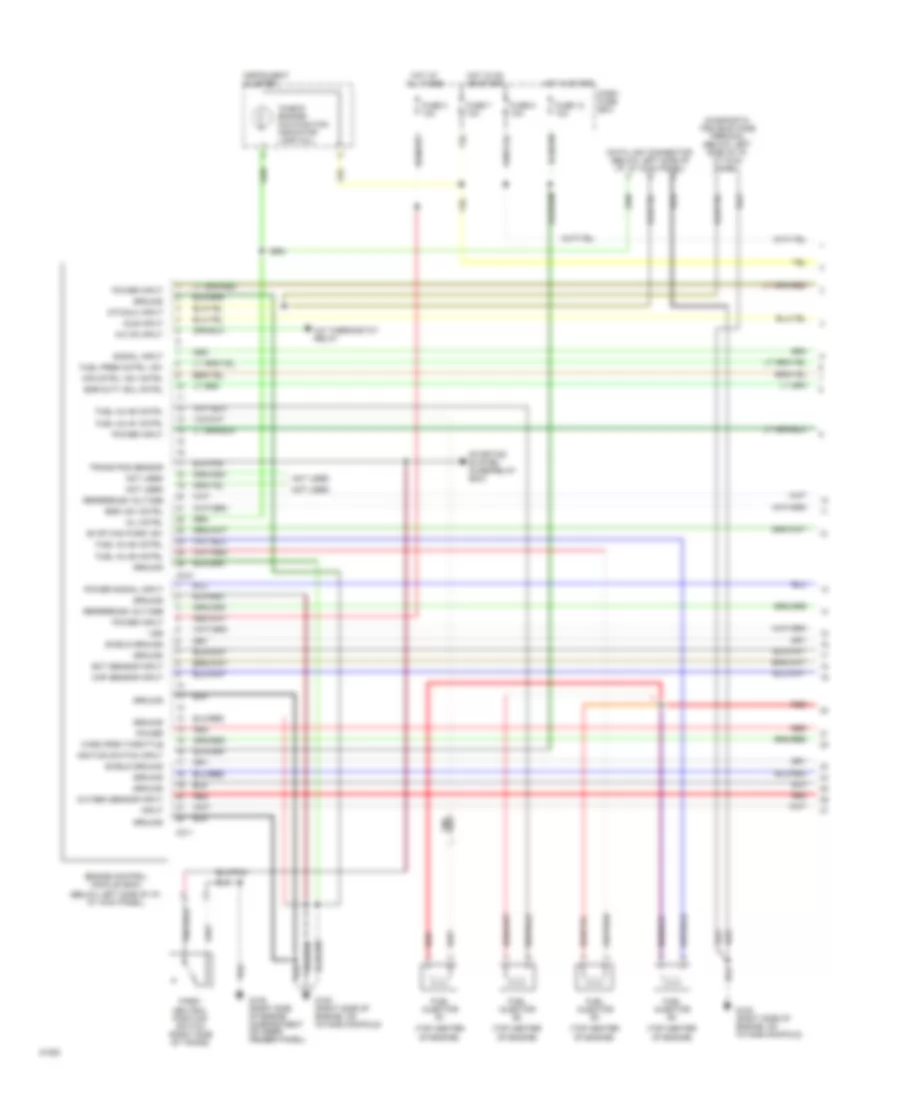
2.6L, Электросхема системы управления двигателя (1 из 3) для Isuzu Pickup S 1994
2.6L, Электросхема системы управления двигателя (1 из 3) для Isuzu Pickup S 1994 - Список элементов:
- "check engine" malfunction indicator lamp (mil)
- (below left side of i/p, at kick panel)
- (top center of engine)
- A/c on input
- A/c thermostat relay
- Air cntrl vsv cntrl
- C210
- C211
- Dash fuse box
- Data link connector (below left side of i/p, at kick panel)
- Diagnostic trouble code terminal (below left side of i/p, at kick panel)
- Dtc/dlc input
- Ect sensor input
- Egr duty sol cntrl
- Egr vsv cntrl
- Engine control module (ecm)
- Evap can purg vsv
- Fuel inj #1 cntrl
- Fuel inj #2 cntrl
- Fuel inj #3 cntrl
- Fuel inj #4 cntrl
- Fuel injector #1
- Fuel injector #2
- Fuel injector #3
- Fuel injector #4
- Fuel pres cntrl vsv
- Fuse 12 10a
- Fuse 3 10a
- Fuse 7 10a
- Fuse 8 10a
- G105 (right side of engine compartment on inner fender panel)
- G120 (right side of engine, on intake manifold)
- Ground
- Hot at all times
- Hot in on or start
- Hot in start
- Idle input
- Ignition switch input
- Input
- Instrument cluster
- Map sensor input
- Mil cntrl
- Not used
- Oxygen sensor input
- Park/ neutral position switch (right side of trans)
- Power
- Power input
- Power signal input
- Red
- Reference voltage
- Shield ground
- Signal input
- Starting system (fuse/relay box)
- Trans pos sensor
- Vss
- Wide open throttle
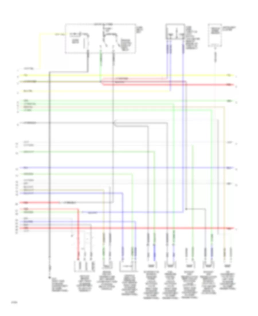
2.6L, Электросхема системы управления двигателя (2 из 3) для Isuzu Pickup S 1994
2.6L, Электросхема системы управления двигателя (2 из 3) для Isuzu Pickup S 1994 - Список элементов:
- (left side of engine compartment on inner fender panel)
- (lower right side of engine, below intake manifold)
- (right side of engine compartment on inner fender panel)
- (top center rear of engine, on valve cover)
- Air flow sensor (left front of engine compartment, on air flow assembly)
- Air management valve (amv)
- Cluster
- Diode box b
- Engine control module (ecm) relay
- Engine coolant temperature (ect) sensor
- Evaporative emission canister purge vacuum switching valve
- Exhaust gas recirculation (egr) duty solenoid (calif only)
- Exhaust gas recirculation (egr) vacuum switching valve (calif only)
- Fuel pressure control valve vacuum switching valve
- Fuse 1 15a
- Fuse/ relay box
- G101 (right side of engine compartment, on inner fender panel)
- Ground
- Hot at all times
- Idle
- Instrument
- Manifold absolute pressure (map) sensor (right side of engine compartment, on inner fender panel)
- Output
- Power
- Red
- Vehicle speed sensor
- Wide open throttle (wot) switch (top center rear of engine, on throttle assembly)
- Wot
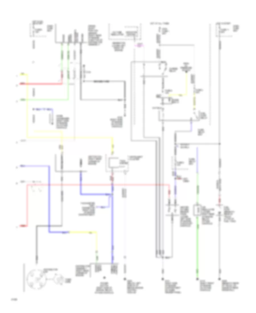
2.6L, Электросхема системы управления двигателя (3 из 3) для Isuzu Pickup S 1994
2.6L, Электросхема системы управления двигателя (3 из 3) для Isuzu Pickup S 1994 - Список элементов:
- (not used)
- Air regulator (lower right rear of engine below intake manifold)
- Braided wire
- C134
- Charge relay
- Coil wire
- Condenser (right side of engine, on intake manifold)
- Crank- shaft position sensor (right rear of engine, in bottom of distributor assembly)
- Dash fuse box
- Diode box a
- Distributor assembly (right rear corner of engine)
- Distributor cap
- From oil pressure switch
- Fuel pump (beneath rear of truck in top of fuel tank)
- Fuel pump relay
- Fuse 11 20a
- Fuse 2 20a
- Fuse 5 10a
- Fuse 6 10a
- Fuse 9 15a
- Fuse/ relay box
- G101 (right side of engine compartment on inner fender panel)
- G119 (right front of engine, on intake manifold)
- G120 (right side of engine on intake manifold)
- G202 (below left side of i/p behind engine control module)
- G409 (beneath rear of truck, on inside of rear frame rail)
- Generator (lower left front of engine)
- Ground
- Heated oxygen sensor (ho2s) (lower left side of engine, in exhaust manifold)
- Hot at all times
- Hot in on or start
- Hot in start
- Ignition coil (right rear corner of engine)
- Indicator control
- Instrument cluster
- Main fuse 1 60a
- Nca
- Noise
- Power
- Power signal input
- Power switch (right side of engine, below intake manifold)
- Primary
- Primary winding control
- Red
- Reference voltage
- Secondary
- Signal output
- Tach- ometer
- Tachometer test connector (right side of engine compartment)
- Timer core
- Voltage regulator
3.1L
3.1L, Электросхема системы управления двигателя (1 из 2) для Isuzu Pickup S 1994
3.1L, Электросхема системы управления двигателя (1 из 2) для Isuzu Pickup S 1994 - Список элементов:
- (below left side of i/p, at kick panel)
- (not used)
- A/c thermostat relay
- A/c control
- A/c cut relay heater- a/c relay
- A/c request input
- A10
- A11
- A12
- B10
- B11
- B12
- Battery input
- Braided
- Bypass cntrl
- C10
- C11
- C12
- C121
- C122
- C123
- C13
- C14
- C15
- C16
- C218
- C219
- Check engine connector (below left side of i/p at kick panel)
- D10
- D11
- D12
- D13
- D14
- D15
- D16
- Dash fuse box
- Data link connector (below left side of i/p, at kick panel)
- Diagnostic input
- Diode box b
- Ect sensor input
- Egr cntrl
- Engine control module (ecm)
- Engine control module relay
- Est output
- Fuel injector #1 (top center of engine)
- Fuel injector #2 (top center of engine)
- Fuel injector cntrl
- Fuel pump (top of fuel tank)
- Fuel pump dlc connector (right rear of engine compartment, on harness)
- Fuel pump relay #1
- Fuel pump relay #2
- Fuel pump relay cntrl
- Fuel pump relay input
- Fuse 1 15a
- Fuse 2 20a
- Fuse 3 10a
- Fuse 8 10a
- Fuse/ relay box
- G101 (right side of engine compt, on inner fender panel)
- G114 (left rear corner of engine, below valve cover)
- G409 (beneath truck bed on rear of right frame rail)
- Ground
- Hot at all times
- Hot in on or start
- Idle air cnrtl
- Idle air cntrl
- Ignition input
- Ignition switch input
- Input
- Knock sensor (ks) module (right side of engine compartment, on bracket)
- Knock sensor (lower right side of engine)
- Map sensor input
- Mil cntrl
- Not used
- O2 sensor input
- Oil pressure switch (lower left side of engine, below oil filter)
- Output
- Oxygen sensor ground
- Pnk
- Power
- Red
- Reference
- Reference voltage
- Serial data out
- Spark retard input
- Starting system
- Tp sensor input
- Vss input
3.1L, Электросхема системы управления двигателя (2 из 2) для Isuzu Pickup S 1994
3.1L, Электросхема системы управления двигателя (2 из 2) для Isuzu Pickup S 1994 - Список элементов:
- "check engine" malfunction indicator lamp (mil)
- Bypass input
- C183
- C189
- C274
- C275
- Coil
- Coil wire
- Dash fuse box
- Distributor assembly (center rear of engine)
- Engine coolant temperature sensor (top center of engine, near coolant outlet)
- Exhaust gas recirculation electronic vacuum regulator solenoid (right rear corner of engine)
- Fuse 7 10a
- Fuse 9 15a
- G110 (left front corner of engine)
- G114 (left rear corner of engine, below valve cover)
- G202 (below left side of i/p, behind ecm)
- Hot in on or start
- Idle air control valve (top center of engine, on intake manifold assembly)
- Ignition coil (right rear corner of engine)
- Ignition control
- Ignition control module
- Instrument cluster
- Manifold absolute pressure sensor (top center of engine, on left side of air cleaner)
- Oxygen sensor (beneath center of vehicle, in exhaust pipe)
- Pick-up
- Pnk
- Power
- Primary
- Primary output
- Reference output
- Secondary
- Tach- ometer
- Throttle position sensor (top center of engine, on intake manifold assembly)
- Timer coil
- Vehicle speed sensor buffer (beneath right front seat)

 Čeština
 Dansk
Dansk Deutsch
 Ελληνικά
 English
 Español
 Suomi
Suomi Français
 Français
 עברית
עברית Hrvatski
 Magyar
 Italiano
 日本語
日本語 한국어
한국어 Nederlands
 Polski
 Português
 Português
 Română
 Русский
 Slovenčina
 Slovenščina
 Svenska
 Türkçe
 中文 (中国)