ANTI-LOCK BRAKES
Anti-lock Brakes Wiring Diagram for Dodge Caliber Rush 2011
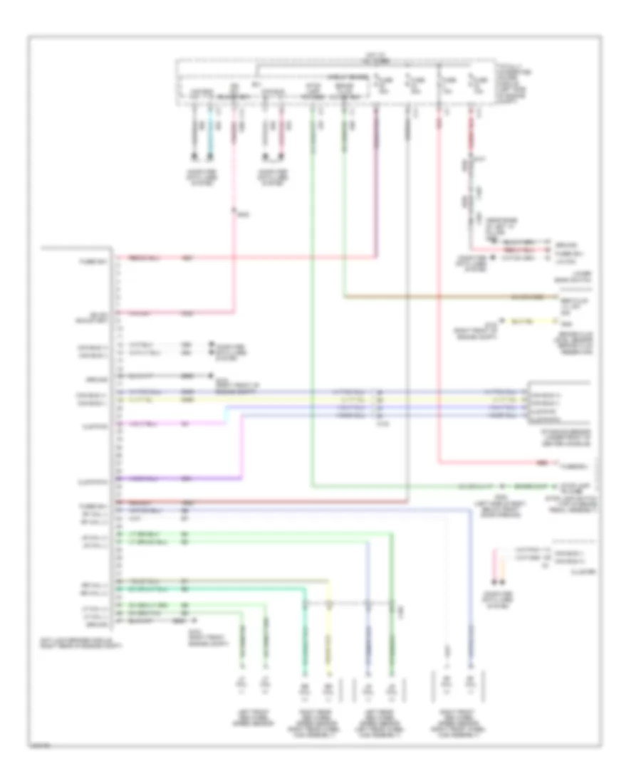
List of elements for Anti-lock Brakes Wiring Diagram for Dodge Caliber Rush 2011:
- (+)
- (-)
- (near base of left "a" pillar) g200
- A921
- A922
- Anti-lock brakes module (right rear of engine compt)
- B(+)
- B20
- Brake fluid level sensor (brake fluid reservoir)
- Brake fluid lvl sw sig
- Brk fluid lvl sw sig
- C103
- C11
- C201
- Can bus
- Can bus (+)
- Can bus (-)
- Circuit board
- Clstr fd
- Clstr rtn
- Cluster
- Computer data lines system
- D464
- D465
- D54
- D55
- D64
- D65
- Dynamics sensor (under front of center console)
- F202
- Fd cmbd
- Fuse 10a
- Fuse 30a
- Fuse 40a
- Fused b(+)
- G104 (right front engine compt)
- G104 (right front of engine compt)
- G94
- Gnd
- Ground
- Hot at all times
- Ign sw (run-start)
- L53
- Left front abs wheel speed sensor
- Left rear abs wheel speed sensor (left rear wheel hub assembly)
- Lf whl
- Lf whl (+)
- Lf whl (-)
- Lin ccn
- Lower bank switch
- Lr whl
- Lr whl (+)
- Lr whl (-)
- Red
- Rf whl
- Rf whl (+)
- Rf whl (-)
- Right front abs wheel speed sensor (right front wheel hub assembly)
- Right rear abs wheel speed sensor (right rear wheel hub assembly)
- Rr whl
- Rr whl (+)
- Rr whl (-)
- S003
- S308 (left side of body, below front door opening)
- Stop lamp
- Stop lamp fm cmbd
- Stop lamp switch (top of brake pedal assembly)
- Totally integrated power module (left side of engine compt)
- Z909
 Čeština
 Dansk
Dansk Deutsch
 Ελληνικά
 English
 Español
 Suomi
Suomi Français
 Français
 עברית
עברית Hrvatski
 Magyar
 Italiano
 日本語
日本語 한국어
한국어 Nederlands
 Polski
 Português
 Português
 Română
 Русский
 Slovenčina
 Slovenščina
 Svenska
 Türkçe
 中文 (中国)
 English