ANTI-LOCK BRAKES
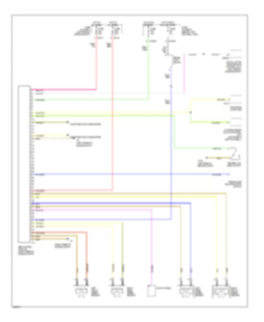
Anti-lock Brakes Wiring Diagram, with Dynamic Stability Control for MINI Cooper 2005
 https://portal-diagnostov.com/license.html
Automotive Electricians Portal FZCO
Automotive Electricians Portal FZCO
https://portal-diagnostov.com/license.html
https://portal-diagnostov.com/license.html
Automotive Electricians Portal FZCO
Automotive Electricians Portal FZCO
List of elements for Anti-lock Brakes Wiring Diagram, with Dynamic Stability Control for MINI Cooper 2005:
- (left door) (coupe) (under left rear seat) (convertible)
- (lower steering column) steering angle sensor
- (right rear of engine compt)
- Abs/dsc unit (right rear of engine compt)
- Brake fluid level switch (left side of engine compt)
- Brake light switch
- Computer data lines system
- Digital motor electronics control unit (left side of engine compt)
- Dsc sensor (transverse acceleration sensor) (under lever cover)
- Fuse f06 30a
- Fuse f2 5a
- Fuse f33 10a
- Fuse f40 5a
- Fuse f6 5a
- Fuse fl6 40a
- Fuse holder 2 (behind left footwell trim)
- Fuse holder 3 (left side of engine compt)
- Hot at all times
- Hot in accy, run and start
- Hot in on or start
- Left front speed sensor
- Left rear speed sensor
- Navigation computer
- Nca
- Outside mirror fold-in control unit (left side of left footwell)
- Pressure sensor 1
- Right front speed sensor
- Right rear speed sensor
- Switch panel
- Tire pressure warning (rdm) switch
- X10200
- X10205
- X10207
- X1313
- X13230
- X1746
- X175 (left side of engine compt)
- X4 (right rear of engine compt)
- X4010
- X4013
- X6004
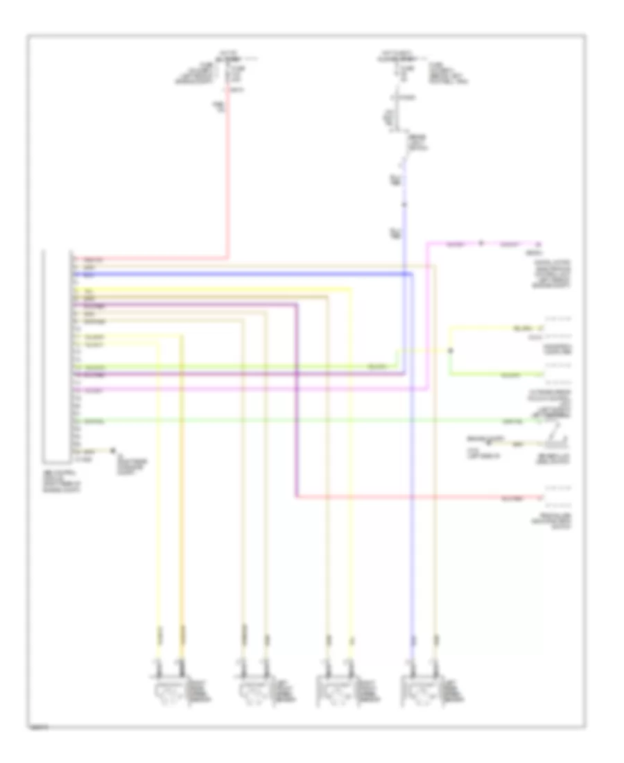
Anti-lock Brakes Wiring Diagram, with Traction Control & without Dynamic Stability Control for MINI Cooper 2005
List of elements for Anti-lock Brakes Wiring Diagram, with Traction Control & without Dynamic Stability Control for MINI Cooper 2005:
- (right rear of engine compt)
- Abs control module (right rear of engine compt)
- Brake fluid level switch
- Brake light switch
- Computer data lines system
- Digital motor electronics control unit (left side of engine compt)
- Fuse f06 30a
- Fuse f33 10a
- Fuse f6 5a
- Fuse fl6 40a
- Fuse holder 2 (behind left footwell trim)
- Fuse holder 3 (left side of engine compt)
- Hot at all times
- Hot in accy, run and start
- Hot in on or start
- Left front speed sensor
- Left rear speed sensor
- Navigation computer
- Nca
- Outside mirror fold-in control unit (left side of left footwell)
- Right front speed sensor
- Right rear speed sensor
- Switch panel
- Tire failure indicator (rpa) switch
- X10200
- X10205
- X11
- X1313
- X175 (left side of engine compt)
- X4010
- X4013
- X60004
Anti-lock Brakes Wiring Diagram, without Traction Control & without Dynamic Stability Control for MINI Cooper 2005
List of elements for Anti-lock Brakes Wiring Diagram, without Traction Control & without Dynamic Stability Control for MINI Cooper 2005:
- Abs control module (right rear of engine compt)
- Brake fluid level switch
- Brake light switch
- Digital motor electronics control unit (left side of engine compt)
- Engine compt)
- Fuse f6 5a
- Fuse fl6 40a
- Fuse holder 2 (behind left footwell trim)
- Fuse holder 3 (left side of engine compt)
- Hot at all times
- Hot in accy, run and start
- Left front speed sensor
- Left rear speed sensor
- Navigation computer
- Nca
- Outside mirror fold-in control unit (left side of left footwell)
- Right front speed sensor
- Right rear speed sensor
- Tire failure indicator (rpa) switch
- X10200
- X11525
- X1313
- X175 (left side of
- X4 (right rear of engine compt.)
- X4010
- X60004

 Čeština
 Dansk
Dansk Deutsch
 Ελληνικά
 English
 Español
 Suomi
Suomi Français
 Français
 עברית
עברית Hrvatski
 Magyar
 Italiano
 日本語
日本語 한국어
한국어 Nederlands
 Polski
 Português
 Português
 Română
 Русский
 Slovenčina
 Slovenščina
 Svenska
 Türkçe
 中文 (中国)