TRANSMISSION
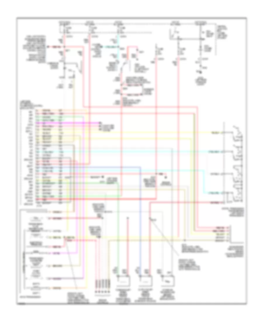
4WD Wiring Diagram for Ford Excursion 2003
List of elements for 4WD Wiring Diagram for Ford Excursion 2003:
- (in backup light switch to rear light feed harn, near breakout to c1220)
- (left side of engine compt) abs control module
- (left side of transmission) digital transmission range sensor
- (pick-up)
- 4wd hi
- 4wd hi ind
- 4wd lo
- 4wd lo ind
- 4wd sw
- 87a
- Auxiliary relay box 3 (left rear side of engine compartment)
- Bpp sw
- Brake pedal position switch (behind left side of dash, above brake pedal)
- C135
- C220b
- C270a
- C270h
- C270m
- C281a
- C281b
- C281c
- C350a
- C350b
- Central junction box (lower left side of dash)
- Clutch pedal position switch
- Computer data lines connector
- Data link connector (behind center of dash)
- Dtr sensor, park brake relay, gas: speed control servo, dsl: vacuum pump motor
- Electronic shift-on-the-fly (esof) solenoid (right side of engine compt)
- Esof sol
- Excursion: pats module, eatc module
- Exterior lights system
- Four-wheel drive control module (behind right side of dash)
- Four-wheel drive switch
- Fuse 10a
- Fuse 15a
- Fuse 30a
- G100 (left rear side of engine compt)
- G201 (behind left side of dash)
- G300 (at floor, in left front footwell)
- Ground
- Hi to lo
- Hot at all times
- Hot in run
- Hot in run or acc
- Hot in run or start
- Hot in start
- Ign (st)
- Ign (st/run)
- Illum
- Instrument cluster
- Instrument cluster, windshield wiper motor, pickup: fuel tank selector switch
- Interior lights system
- Iso bus
- Lo to hi
- Main light switch, accelerator pedal position sensor, main light switch, instrument cluster, auxiliary powertrain control module, grade/load switch, clutch triple function switch jumper, overdrive cancel switch
- Motor 2
- Motor 3
- Motor 4
- Motor 5
- Nuet sens
- Off
- Pickup
- Red
- Ref volt
- Reverse
- S124
- S199
- S201
- S205 (behind left side of dash)
- S225 (behind instrument cluster)
- S228
- S250
- S253 (main harn, at breakout for instrument cluster)
- S254
- S255
- S257
- S271
- S275
- Shift sol
- Transfer case assembly
- Transfer case high to low relay
- Transfer case low to high relay
- Vpwr
- Vss in
- Vss out
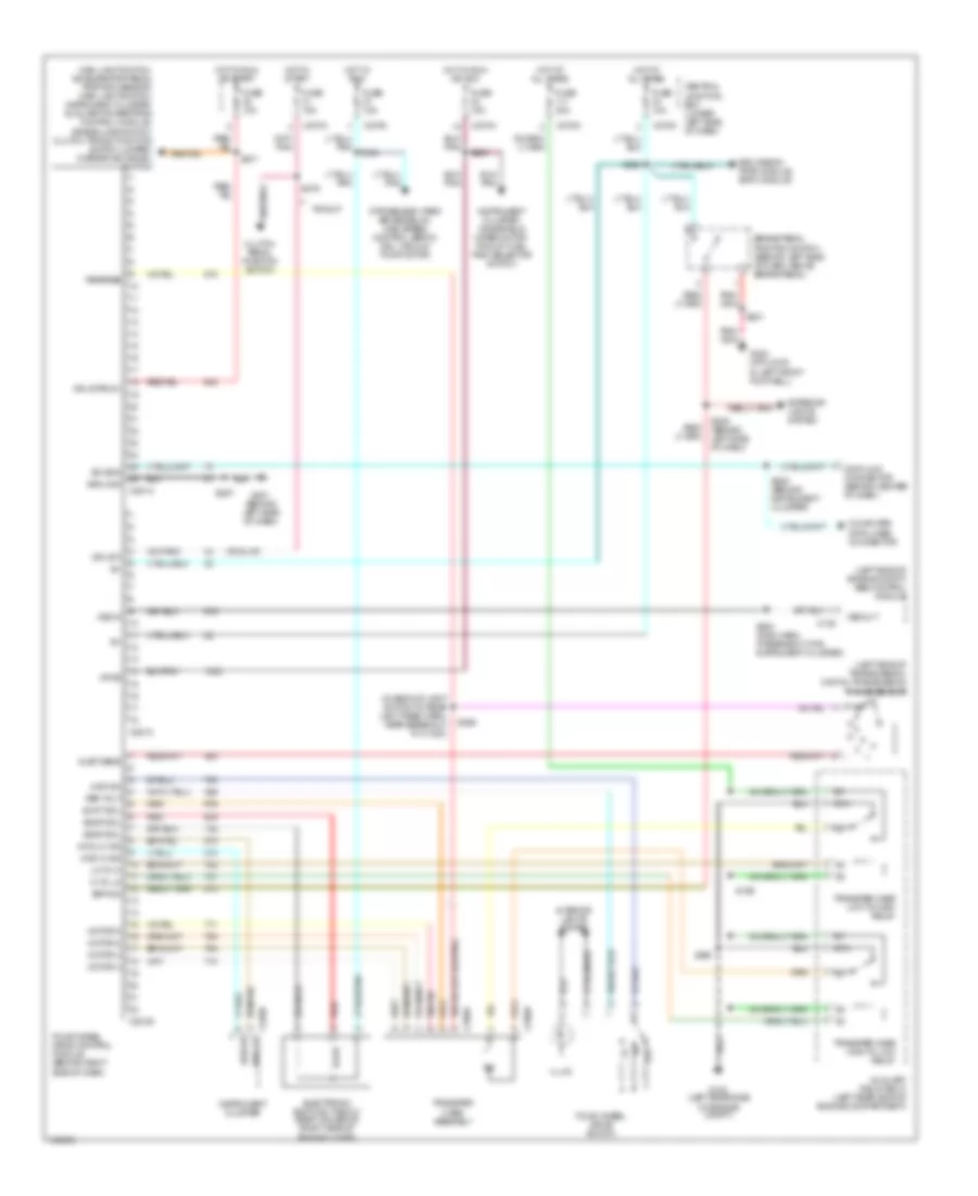
5.4L
5.4L, A/T Wiring Diagram for Ford Excursion 2003
List of elements for 5.4L, A/T Wiring Diagram for Ford Excursion 2003:
- (5.4l calif) s133
- (backup light sw to rear light feed harn, near breakout for auto trans module)
- (eng cntrl harn, near breakout for brake pressure switch)
- (eng cntrl harn, near breakout for g100 s122
- (in main harn, near breakout to brake pedal position switch)
- (left side of firewall) powertrain control module (pcm)
- 4-wheel drive control module, pats module, eatc module
- 4r100 transmission
- Bpp sw
- Brake pedal position switch
- C175
- C270a
- C270f
- C270h
- Ccs
- Central junction box (lower left side of dash)
- Cht
- Coast clutch
- Computer data lines system
- Control solenoids
- Cylinder head temperature sender (on right cylinder head)
- Data
- Digital transmission range sensor (left side of transmission)
- Electronic pressure
- Engine controls
- Epc
- Exterior lights system
- Fuse 10a
- Fuse 20a
- G100 (left rear of engine compt)
- G101 (left rear of engine compt)
- G300 (at floor, in left front footwell)
- Ground
- Hot at all times
- Hot in run or start
- Iat
- Maf
- Main light switch, accelerator pedal position sensor, main light switch, instrument cluster, overdrive cancel switch
- Mass airflow sensor (left front of engine compt)
- Nca
- Near breakout for g101)
- Oss
- Output shaft speed sensor (top of transmission extension housing)
- Overdrive cancel switch
- Pcm power diode
- Pcm power relay
- R p
- Red
- S106
- S114 (eng cntrl narn near breakout for g101)
- S123 (in eng cntrl harn, near breakout for powertrain control module)
- S132
- S138
- S139
- S162
- S170 (calif)
- S201
- S205
- S228
- S271
- Scp (+)
- Scp (-)
- Shift 1
- Shift 2
- Sig rtn
- Ss1
- Ss2
- Tcc
- Tcil
- Tcs
- Tft
- Throttle position (tp) sensor (on throttle body)
- Tr1
- Tr2
- Tr3
- Tr4
- Transmission converter clutch
- Transmission fluid temperature sensor
- Tss
- Turbine shaft speed sensor (top of transmission at converter housing)
- Vpwr
- Vref
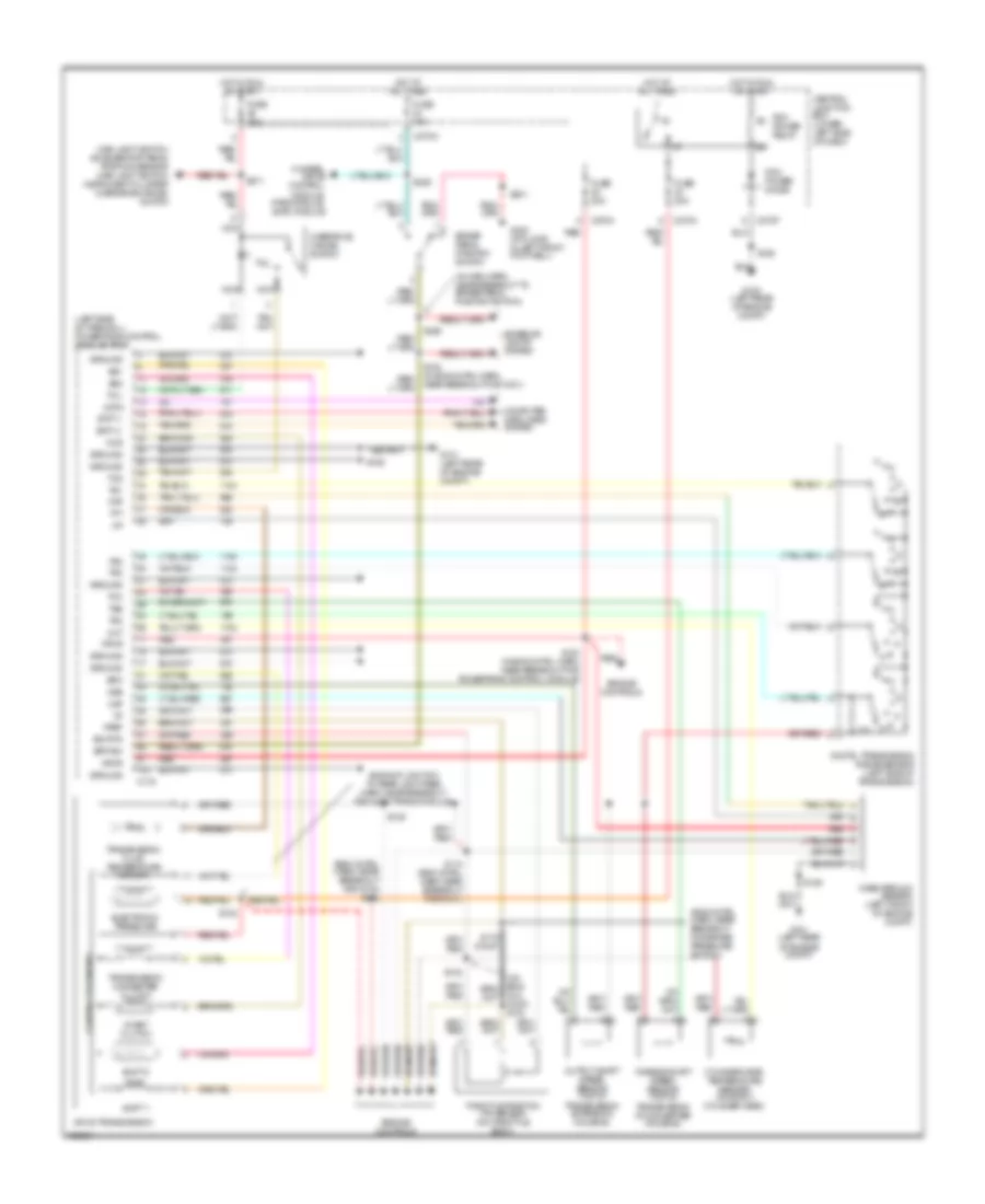
6.0L DIESEL
6.0L Diesel, A/T Wiring Diagram (1 of 2) for Ford Excursion 2003
List of elements for 6.0L Diesel, A/T Wiring Diagram (1 of 2) for Ford Excursion 2003:
- (in engine con- trol sensor & fuel charge harn, at break- out for air charge temp sensor)
- (in engine control harn, near breakout for g101)
- (in main harn, near breakout to brake pedal position switch) s224
- (maf) sens out
- Acc
- Brake ped pos sw
- Brake pedal position (bpp) switch (behind left side of dash, above brake pedal)
- Brake pressure switch, egr valve actuator, injection pressure regulator, glow plug control module
- C1381a
- C1381c
- C270a
- C270h red
- Can bus 1h
- Can bus 1l
- Central junction box (behind lower left side of dash)
- Chassis gnd
- Cool temp sens
- Data link connector (dlc) (behind left side of dash)
- Egr thrtl pos
- Engine coolant temperature (ect) sensor
- Fuse 10a
- Fuse 20a
- Fuse 30a
- G100
- G101
- G300 (on vehicle floor, in left front footwell)
- Grade/load switch
- Grd/load sw
- Hot at all times
- Hot in run or start
- Ignition switch
- Injector driver module, fuel heater relay
- Intk air temp sens
- Lock
- Maf sens sig rtn
- Main light switch, accelerator pedal position sensor, main light switch, instrument cluster, auxiliary powertrain control module, clutch triple function switch jumper, grade/load switch
- Mass airflow (maf) sensor
- Nca
- Off
- Pcm power diode
- Pcm power relay
- Powertrain control module (pcm) (on left side of firewall)
- Pwr gnd
- Pwr in
- Red
- Ref volt
- Run
- S101
- S106
- S114
- S123
- S162
- S190
- S192
- S271
- Sig rtn
- Start
- Throttle position (tps) sensor
- To fuel pump relay
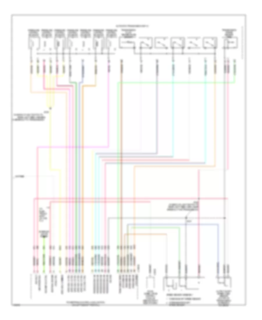
6.0L Diesel, A/T Wiring Diagram (2 of 2) for Ford Excursion 2003
List of elements for 6.0L Diesel, A/T Wiring Diagram (2 of 2) for Ford Excursion 2003:
- (epc) sol 1 ctrl
- (epc) sol 2 ctrl
- (epc) sol 3 ctrl
- (epc) sol 4 ctrl
- (epc) sol 5 ctrl
- (epc) sol common
- (in back-up light switch to
- (iss) sens in
- (on left side of firewall)
- (oss) sens in
- (tcc) sol ctrl
- (tcil) ctrl
- (tft) sens
- (tft) sens in
- (tss) sens in
- (w/ elec- tronic shift on the fly)
- Automatic transmission 5r110
- C1381b
- C281b
- Exterior lights system
- Four- wheel drive control module (behind right side of dash)
- In breakout to transmission)
- Intermediate shaft
- Line press sol
- Neutral sw sen
- Output shaft speed (oss) sensor (on top of transmission extension housing)
- Powertrain control module (pcm)
- Pressure control solenoid
- Pressure sw 1 in
- Pressure sw 2 in
- Pressure sw 3 in
- Pressure sw 4 in
- Pressure sw 5 in
- Rear light feed harness,
- Ref volt
- Rev lmp rly ctrl
- S127
- S128 (in back-up light switch to rear light feed harn, near breakout for transmission)
- S129
- Sig rtn
- Speed sensor
- Speed sensor assembly
- Tran range sens
- Transmission fluid temperature sensor
- Transmission range sensor (trs)
- Turbine shaft speed sensor
6.8L
6.8L, A/T Wiring Diagram for Ford Excursion 2003
List of elements for 6.8L, A/T Wiring Diagram for Ford Excursion 2003:
- (5.4l calif) s133
- (backup light sw to rear light feed harn, near breakout for auto trans module)
- (eng cntrl harn, near breakout for brake pressure switch)
- (eng cntrl harn, near breakout for g100 s122
- (in main harn, near breakout to brake pedal position switch)
- (left side of firewall) powertrain control module (pcm)
- 4-wheel drive control module, pats module, eatc module
- 4r100 transmission
- Bpp sw
- Brake pedal position switch
- C175
- C270a
- C270f
- C270h
- Ccs
- Central junction box (lower left side of dash)
- Cht
- Coast clutch
- Computer data lines system
- Control solenoids
- Cylinder head temperature sender (on right cylinder head)
- Data
- Digital transmission range sensor (left side of transmission)
- Electronic pressure
- Engine controls
- Epc
- Exterior lights system
- Fuse 10a
- Fuse 20a
- G100 (left rear of engine compt)
- G101 (left rear of engine compt)
- G300 (at floor, in left front footwell)
- Ground
- Hot at all times
- Hot in run or start
- Iat
- Maf
- Main light switch, accelerator pedal position sensor, main light switch, instrument cluster, overdrive cancel switch
- Mass airflow sensor (left front of engine compt)
- Nca
- Near breakout for g101)
- Oss
- Output shaft speed sensor (top of transmission extension housing)
- Overdrive cancel switch
- Pcm power diode
- Pcm power relay
- R p
- Red
- S106
- S114 (eng cntrl narn near breakout for g101)
- S123 (in eng cntrl harn, near breakout for powertrain control module)
- S132
- S138
- S139
- S162
- S170 (calif)
- S201
- S205
- S228
- S271
- Scp (+)
- Scp (-)
- Shift 1
- Shift 2
- Sig rtn
- Ss1
- Ss2
- Tcc
- Tcil
- Tcs
- Tft
- Throttle position (tp) sensor (on throttle body)
- Tr1
- Tr2
- Tr3
- Tr4
- Transmission converter clutch
- Transmission fluid temperature sensor
- Tss
- Turbine shaft speed sensor (top of transmission at converter housing)
- Vpwr
- Vref
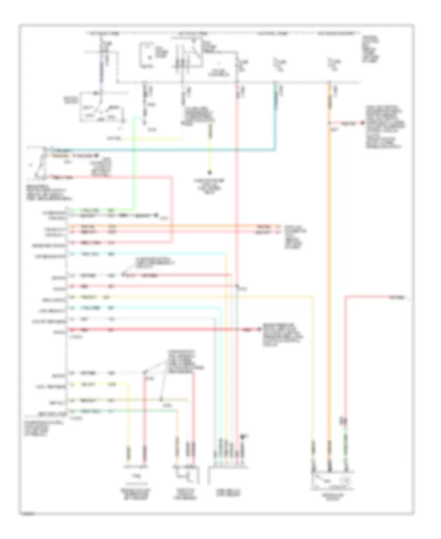
7.3L DIESEL
7.3L Diesel, A/T Wiring Diagram for Ford Excursion 2003
List of elements for 7.3L Diesel, A/T Wiring Diagram for Ford Excursion 2003:
- (backup light switch to rear light feed harn, near breakout for auto trans module)
- (eng cntrl harn, near breakout for g100) s122
- (eng cntrl harn, near breakout for g101)
- (left side of engine compt)
- (left side of firewall) powertrain control module (pcm)
- (main harn, near breakout to brake pedal position switch)
- 4-wheel drive control, pats & eatc module
- 4r100 transmission
- Accelerator pedal position sensor (on accelerator pedal support)
- App
- Bpp sw
- Brake pedal position switch
- C175
- C270a
- C270f
- C270g
- C270h
- Ccs
- Central junction box (lower left side of dash)
- Coast clutch
- Computer data lines system
- Control solenoids
- Data
- Digital transmission range sensor (left side of transmission)
- Electronic pressure
- Engine controls
- Epc
- Exterior lights system
- Fuse 10a
- Fuse 20a
- G100 (left rear of engine compt)
- G101
- G300 (at floor, in left front footwell)
- Ground
- Hot at all times
- Hot in run or start
- Iat
- Intake air temperature sensor (left side of engine compt)
- Main light switch, accelerator pedal position sensor, main light switch, instrument cluster, auxiliary powertrain control module, clutch triple function switch jumper, overdrive cancel switch
- Nca
- Near breakout for g101)
- Oss
- Output shaft speed sensor (top of transmission extension housing)
- Overdrive cancel switch
- Pcm power diode
- Pcm power relay
- R p
- Red
- S106
- S114
- S123 (eng cntrl harn, near breakout for g100)
- S138
- S139
- S162
- S170 (eng cntrl harn, near breakout for brake pressure switch)
- S201
- S205
- S228
- S271
- Scp (+)
- Scp (-)
- Shift 1
- Shift 2
- Sig rtn
- Ss1
- Ss2
- Tcc
- Tcil
- Tcs
- Tft
- Tr1
- Tr2
- Tr3
- Tr4
- Transmission converter clutch
- Transmission fluid temperature sensor
- Tss
- Turbine shaft speed sensor (top of transmission, at converter housing)
- Vbatt
- Vpwr
- Vref

 Čeština
 Dansk
Dansk Deutsch
 Ελληνικά
 English
 Español
 Suomi
Suomi Français
 Français
 עברית
עברית Hrvatski
 Magyar
 Italiano
 日本語
日本語 한국어
한국어 Nederlands
 Polski
 Português
 Português
 Română
 Русский
 Slovenčina
 Slovenščina
 Svenska
 Türkçe
 中文 (中国)