POWER DISTRIBUTION
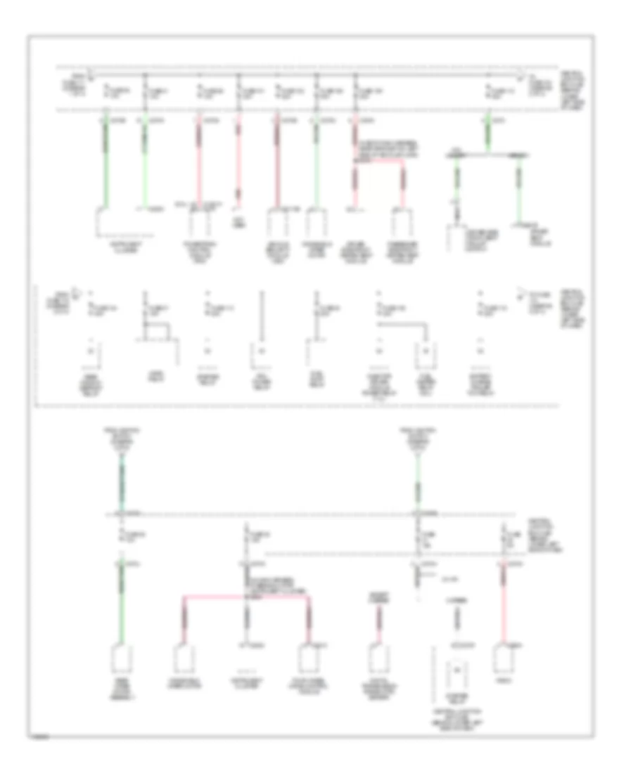
Power Distribution Wiring Diagram (1 of 4) for Ford Excursion 2003

List of elements for Power Distribution Wiring Diagram (1 of 4) for Ford Excursion 2003:
- (behind left side of dash)
- (in back-up light switch to rear light feed harness, at breakout for auxiliary relay box 3) s199
- (in engine control harness, at breakout for auxiliary relay box 4) s103
- (in main harness, near breakout for auxiliary relay box 1) s249
- (in main harness, near breakout for data link connector) s242
- (in main harness, near breakout for instrument cluster) s228
- (in main harness, near breakout to brake pedal position switch) s214
- (in main harness, near breakout to main light switch) s272
- (left ``c" pillar)
- (near breakout for abs control module) s163
- (right ``d" pillar)
- 30a
- 6.0l
- A/c clutch relay
- Abs control module
- Accessory delay relay
- Adjustable pedal switch
- Auxiliary a/c relay
- Auxiliary relay box 1 (behind glove box)
- Auxiliary relay box 3 (left rear side of engine compt)
- Auxiliary relay box 4
- Auxiliary relay box 4 (left rear side of engine compt)
- Auxiliary relay box 5 (left rear side of engine compt)
- Battery
- Battery ii (6.0l/7.3l)
- Brake pedal position switch
- Brake pressure switch (5.4l/6.8l)
- C202a
- C205a
- C2113b
- C228b
- C270a
- C270b
- C270d
- C270e
- C270g
- C270h
- C270i
- C270j
- C270k
- C270m
- C281c
- C290a
- C341c
- Central junction box (cjb) (behind lower left side of dash)
- Console power point
- Data link connector (dlc)
- Daytime running lamps resistor
- Driver seat module
- Driver side front seat adjust switch
- Dvd player
- Electronic automatic temperature control (eatc) module
- Except 6.0l
- Exterior rear view mirror switch
- Four-wheel drive control module
- From a fuse 10 (diagram 1 of 4)
- From b fuse 16 (diagram 1 of 4)
- Front cigar lighter
- Fuse
- Fuse 1 15a
- Fuse 108 40a
- Fuse 10a
- Fuse 11 20a
- Fuse 111 30a
- Fuse 12 20a
- Fuse 13 10a
- Fuse 14 15a
- Fuse 15 10a
- Fuse 16 15a
- Fuse 17 15a
- Fuse 18 20a
- Fuse 19 5a
- Fuse 2 20a
- Fuse 20 10a
- Fuse 21 25a
- Fuse 3 20a
- Fuse 34 10a
- Fuse 4 20a
- Fuse 5 20a
- Fuse 6 20a
- Fuse 602 60a
- Fuse 7 30a
- G201
- G201 (behind left side of dash)
- G202
- G301
- G403
- Indicator flasher relay
- Injector driver module (idm) power relay
- Instru- ment panel power point
- Junction block
- Left turn trailer tow relay
- Main light switch
- Multifunction switch
- Nca
- Passenger side front seat adjust switch
- Passive anti-theft transceiver module
- Power choke 2
- Radio
- Rear integrated control panel
- Rear power point
- Rear wiper motor assembly
- Red
- Right turn trailer tow relay
- S1000 (in battery output harness, at breakout for junction block on left fender)
- S1002 (in battery output harness, near grommet on firewall)
- S290
- S300
- S316 (in body main harness, near grommet on left side of vehicle floor)
- S323
- S324
- To fuse (diagram 2 of 4)
- To fuse 108 (diagram 1 of 4)
- To fuse 12 (diagram 1 of 4)
- Transfer case high to low relay
- Transfer case low to high relay
- Vehicle security module (vsm)
- Video cassette player
- W/o video cassette player
- ``c" pillar power point
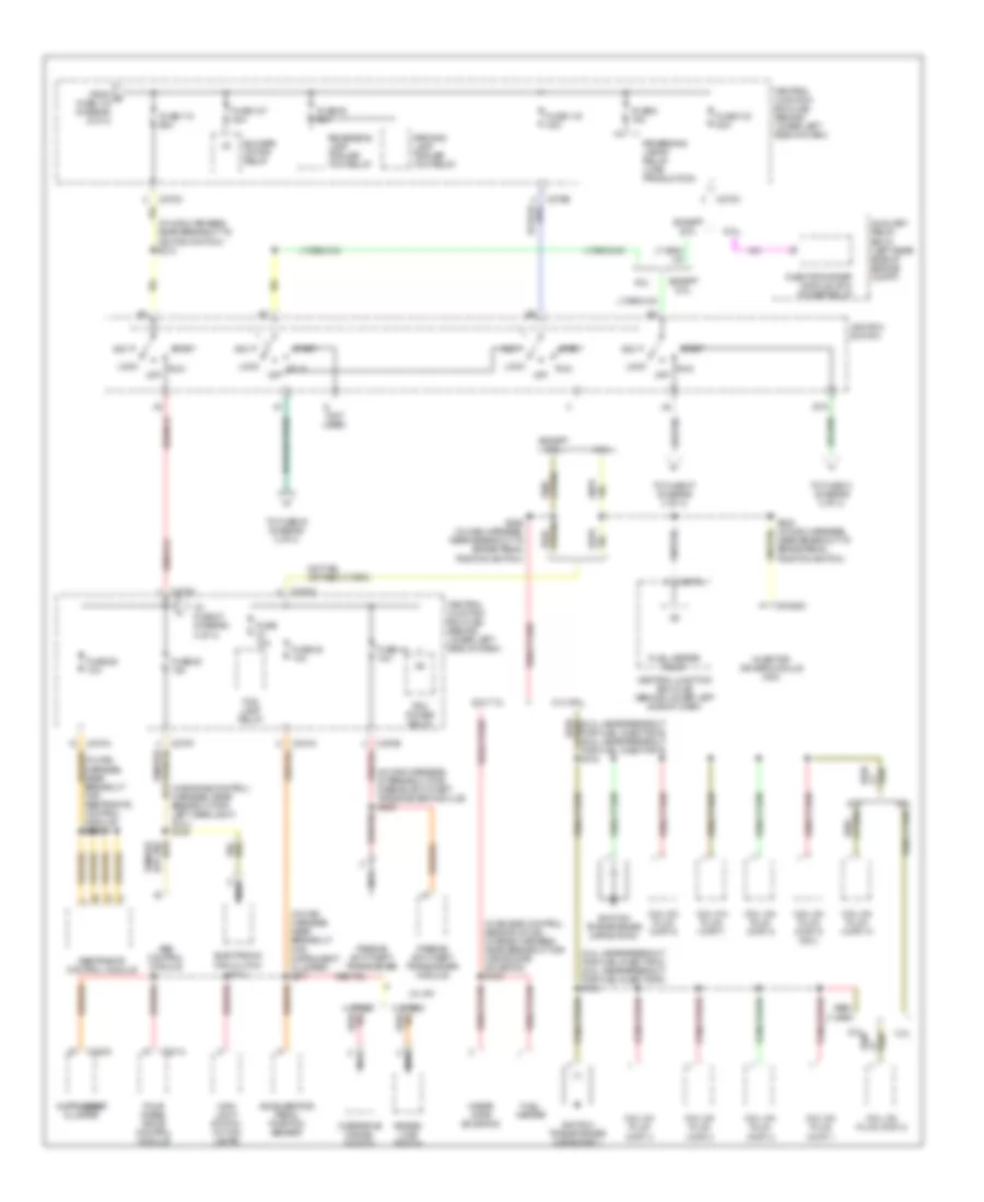
Power Distribution Wiring Diagram (2 of 4) for Ford Excursion 2003
List of elements for Power Distribution Wiring Diagram (2 of 4) for Ford Excursion 2003:
- (6.0l)
- (in body main harness, near grommet on left side of vehicle floor) s315
- (in main harness, at breakout for instrument cluster) s254
- (w/ a/t)
- 5 speed
- Battery charge trailer tow relay
- C1381a c175
- C2113b
- C220c
- C270a
- C270b
- C270c
- C270e
- C270f
- C270g
- C270h
- C270i
- C270j
- C270k
- C270m
- C281c
- C290a
- C341b
- Central junction box (cjb) (behind lower left side of dash)
- Digital transmission range (dtr) sensor
- Driver seat module
- Driver side front heated seat module
- Driver side front seat adjust switch
- Except 5 speed
- Four-wheel drive control module
- From c fuse 111 (diagram 1 of 4)
- From d fuse 112 (diagram 2 of 4)
- From ignition switch (diagram 3 of 4)
- Fuel heater relay (6.0l)
- Fuel pump relay
- Fuse 101 30a
- Fuse 102 30a
- Fuse 104 40a
- Fuse 105 30a
- Fuse 106 30a
- Fuse 109 30a
- Fuse 112 30a
- Fuse 113 30a
- Fuse 115 20a
- Fuse 15a
- Fuse 33 15a
- Fuse 35 10a
- Fuse 36 10a
- Fuse 37 15a
- Fuse 40 20a
- Fuse 41 10a
- Fuse 48 10a
- Fuse 5a
- Horn relay
- Injector driver module power relay (7.3l)
- Instrument cluster
- Memory
- Nca
- Not used
- Passenger side front heated seat module
- Pcm power relay
- Powertrain control module (pcm)
- Radio
- Rear window defrost relay
- Rear wiper motor assembly
- Red
- Starter relay
- To fuse (diagram 3 of 4)
- To fuse 104 (diagram 2 of 4)
- Vehicle security module (vsm)
- W/o memory
- Windshield wiper motor
Power Distribution Wiring Diagram (3 of 4) for Ford Excursion 2003
List of elements for Power Distribution Wiring Diagram (3 of 4) for Ford Excursion 2003:
- (5.4l: near breakout for fuel injector 3) (6.8l: near breakout for fuel injector 5) s135
- (5.4l: near breakout for fuel injector 6) (6.8l: near breakout for fuel injector 9) s130
- (in engine control harness, near breakout for left headlight) (6.0l) s109
- (in engine control sensor & fuel charge harness, near breakout for waste gate solenoid) s154
- (in main harness, at breakout for passive anti-theft transceiver module) s209
- (in main harness, near breakout for instrument cluster) s271
- (in main harness, near breakout to ignition switch) s210
- (not used)
- (w/ a/t)
- 4 speed
- 5 speed
- 5.4l
- 5.4l/6.8l
- 6.0l
- 6.0l/7.3l
- 6.8l
- Abs control module
- Acc
- Accelerator pedal position sensor
- Auxiliary relay box 5 (left rear side of engine compt)
- Blower motor relay
- C1388c
- C220c
- C270a
- C270b
- C270c
- C270e
- C270f
- C281a
- Central junction box (cjb) (behind lower left side of dash)
- Coil on plug (cop) 1
- Coil on plug (cop) 10
- Coil on plug (cop) 2
- Coil on plug (cop) 3
- Coil on plug (cop) 4
- Coil on plug (cop) 5
- Coil on plug (cop) 6
- Coil on plug (cop) 7
- Coil on plug (cop) 8
- Coil on plug (cop) 9 (6.8l)
- Electronic fan clutch (6.0l)
- Except 6.0l
- Fog lamp relay
- Four wheel drive control module
- From e fuse 115 (diagram 2 of 4)
- Fuel heater
- Fuel heater relay
- Fuse 103 50a
- Fuse 107 40a
- Fuse 10a
- Fuse 110 50a
- Fuse 116 30a
- Fuse 25 10a
- Fuse 26 10a
- Fuse 38 20a
- Fuse 44 10a
- Fuse 45 10a
- Fuse 8 15a
- Grade/ load switch
- Ignition switch
- Ignition transformer capacitor 1
- Ignition transformer capacitor 2
- Injector driver module (idm)
- Injector driver module (idm) power relay
- Instrument cluster
- Lock
- Main light switch (w/ fog lamps)
- Nca
- Off
- Overdrive cancel switch
- Parking lamp trailer tow relay
- Passive anti-theft transceiver
- Passive anti-theft transceiver module
- Pcm power relay
- Red/
- Restraints control module
- Reversing lamp trailer tow relay
- Reversing lamps relay (late production)
- Run
- S224 (in main harness, near breakout to brake pedal position switch)
- S258 (in main harness, near breakout to brake pedal position switch)
- Sta
- Start
- To fuse 27 (diagram 4 of 4)
- To fuse 31 (diagram 2 of 4)
- To fuse 48 (diagram 2 of 4)
- Waste gate solenoid
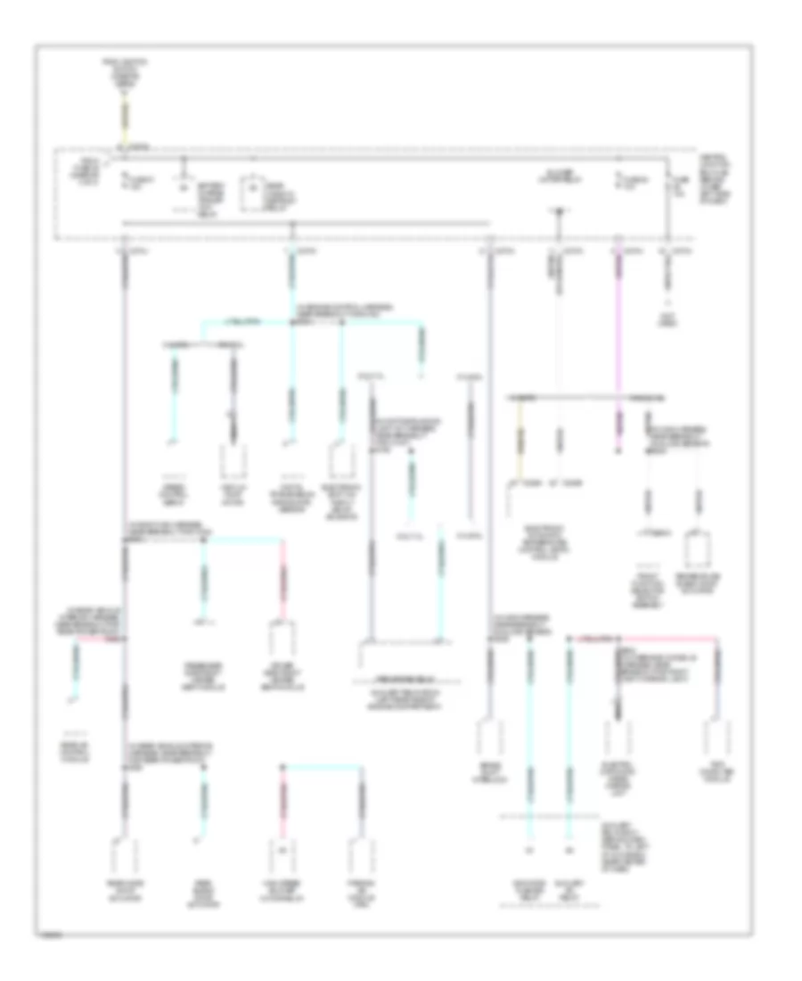
Power Distribution Wiring Diagram (4 of 4) for Ford Excursion 2003
List of elements for Power Distribution Wiring Diagram (4 of 4) for Ford Excursion 2003:
- (in body main harness, near breakout for c340) s303
- (in daytime running light kit harness, near breakout for c1047) s198
- (in engine control harness, near breakout for g100) s124
- (in main harness, near breakout sunload sensor) s206
- (in main harness, near breakout sunload sensor) s235
- (in overhead console harness, near breakout for right vanity mirror light)
- (in rear vehicle interior harness, near breakout for rear power point) s320
- (in rear vehicle interior harness, near breakout for rear power point) s322
- (not used)
- 5.4l/6.8l
- 6.0l/7.3l
- Auxiliary a/c relay
- Auxiliary relay box 1 (behind dash panel, to left of glove box near center of dash)
- Auxiliary relay box 2 (left rear side of engine compartment)
- Battery charge trailer tow relay
- Blower motor relay
- Brake shift interlock
- C228a
- C228b
- C270a
- C270c
- C270h
- C294a
- Central junction box (cjb) (behind lower left side of dash)
- Digital transmission range (dtr) sensor
- Driver side front heated seat module
- Electro- chromatic inside mirror unit
- Electronic automatic temperature control (eatc) module
- Electronic shift on the fly (ecof) solenoid
- From ignition switch (diagram 3 of 4)
- From j fuse 25 (diagram 3 of 4)
- Front function selector switch assembly
- Fuse 10a
- Fuse 27 15a
- Fuse 28 10a
- High speed blower motor relay
- Indicator flasher relay
- Manual a/c
- Nca
- Park brake relay
- Parking aid module (pam)
- Passenger side front heated seat module
- Rear a/c control module
- Rear blend door actuator
- Rear mode door actuator
- Rear window defrost relay
- Speed control servo
- Temperature blend door actuator
- Trip computer module
- Vaccum pump motor
- W/ eatc