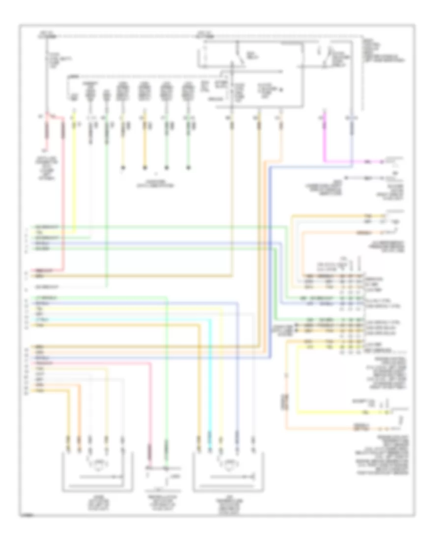
AIR CONDITIONING
Automatic A/C Wiring Diagram (1 of 2) for Saturn Aura XR 2008
 https://portal-diagnostov.com/license.html
Automotive Electricians Portal FZCO
Automotive Electricians Portal FZCO
https://portal-diagnostov.com/license.html
https://portal-diagnostov.com/license.html
Automotive Electricians Portal FZCO
Automotive Electricians Portal FZCO
List of elements for Automatic A/C Wiring Diagram (1 of 2) for Saturn Aura XR 2008:
- (2.4l (vin 5)) (in engine harness) b
- (2.4l (vin b): left rear of engine) (3.5l: rear of engine, above oil filter) (2.4l (vin 5): rear of engine, near pnp switch) g106
- (in engine harness) (2.4l (vin 5)) j153
- 2.4l (vin b)
- 3.5l
- 5 volt ref
- 87a
- A/c clu fuse 1 10a
- A/c clutch relay
- A/c compressor clutch (lower left, front of engine, part of a/c compressor)
- A/c request ind
- A/c request switch
- A11 x2
- A2 x1
- A5 x2
- Air temp dr pos sig
- Ambient air temperature sensor (left front impact bar, behind grille)
- Auto
- B10
- B10 x2
- Bas pmp fuse 20a
- Battery positive
- Computer data lines system
- Cool fan 1 fuse 17 30a
- Cool fan 2 fuse 18 30a
- Cool/ fan 1 relay
- Cool/ fan 2 relay
- Cool/fan ser/par relay
- Defog ind
- Defog switch
- Door position sig
- Dr ctrl a
- Dr ctrl b
- E1 x2
- E8 x1
- Except 2.4l (vin b)
- Except 3.5l
- F3 x1
- Fresh air ind
- Fresh air switch
- G106 (2.4l (vin b): left rear of engine) (3.5l: rear of engine, above oil filter) (2.4l (vin 5): rear of engine, near pnp switch)
- G201 (under dash, right side of console, near floor)
- Gnd
- Heater coolant pump (middle rear of engine)
- High
- Hot at all times
- Hot w/ pwr/trn relay energized
- Hvac control module
- Ign 3 vol
- Left cooling fan (left rear of radiator)
- Left engine cooling fan diode (2.4l (vin 5))
- Logic
- Low blower motor switch
- Low ref
- Lower air temperature sensor (behind right console access panel)
- Lower air temperature switch
- Mode dr pos sig
- Mode switch
- Off
- Pnk
- Power distribution system
- Recir door ctrl
- Recirculation ind
- Recirculation switch
- Req sig
- Right cooling fan (right rear of radiator)
- Right engine cooling fan diode (2.4l (vin 5))
- Serial data
- Signal
- Starter generator control module (sgcm) (left front engine compt)
- Tan
- Underhood fuse block (left side of engine compt, next to battery)
- Upper air temperature sensor (inside left center a/c duct)
- Upper air temperature switch
- X1 e3
- X3 b9
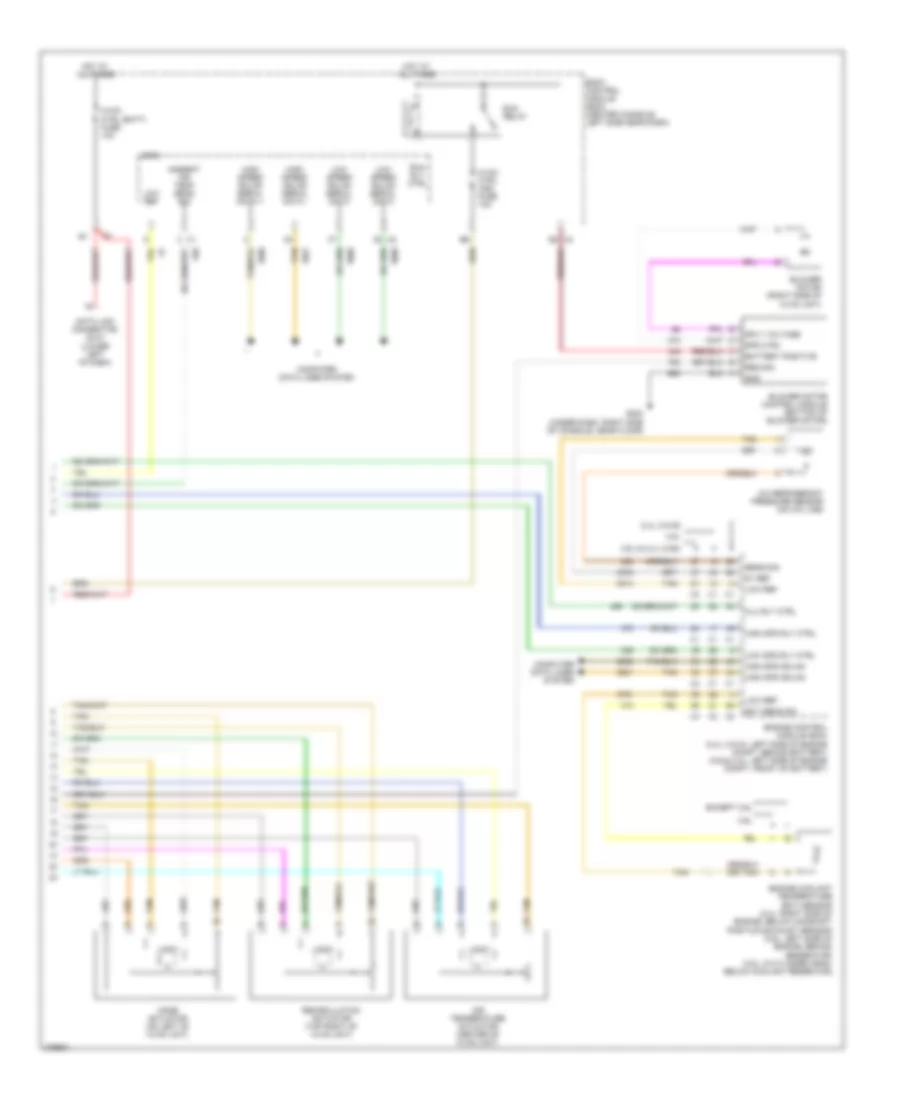
Automatic A/C Wiring Diagram (2 of 2) for Saturn Aura XR 2008
List of elements for Automatic A/C Wiring Diagram (2 of 2) for Saturn Aura XR 2008:
- 2.4l (vin b)
- 3.5l
- 3.6l
- 3.6l & 2.4l (vin5)
- 5v ref
- A/c refrigerant pressure sensor (on a/c line)
- Air temperature actuator (center of hvac unit)
- Ambient air temp sens sig
- Battery positive
- Blower motor (right side of hvac unit)
- Blower motor control module (bottom of blower motor)
- Body control module (bcm) (center console, left side near dash)
- Clu rly ctrl
- Computer data lines system
- Data link connector (dlc) (lower left of dash)
- E2 x4
- Ect sens sig
- Engine control module (ecm) (2.4l (vin 5): left side of engine compt, behind battery) (3.6l& 3.4l: left side of engine compt, front of battery)
- Engine coolant temperature (ect) sensor (2.4l: right side of engine, below camshaft position exhaust sensor) (3.6l: left side of engine, behind generator) (3.5l: in cylinder head, below coolant reservoir)
- Except 3.6l
- G203 (under dash, right side of console, near floor)
- Gnd
- High spd gmlan
- High spd rly ctrl
- High speed gmlan serial data +
- High speed gmlan serial data -
- Hot at all times
- Hvac ctrl (batt) fuse 10a
- Hvac ctrl (ign) fuse 10a
- Logic
- Low ref
- Low spd rly ctrl
- Low speed gmlan serial data
- Mode actuator (on left of hvac unit)
- Recirculation actuator (top right of hvac unit)
- Req sig
- Run relay
- Run rly ctrl
- Sens sig
- Spd ctrl
- Sply voltage
- Tan
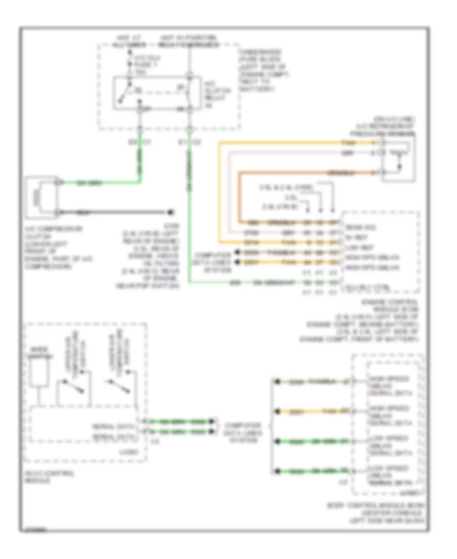
Compressor Wiring Diagram, with Auto A/C for Saturn Aura XR 2008
List of elements for Compressor Wiring Diagram, with Auto A/C for Saturn Aura XR 2008:
- (on a/c line) a/c refrigerant pressure sensor
- 2.4l (vin b)
- 3.5l
- 3.6l & 2.4l (vin5)
- 5v ref
- A/c clu fuse 1 10a
- A/c clutch relay
- A/c compressor clutch (lower left front of engine, part of a/c compressor)
- Body control module (bcm) (center console, left side near dash)
- C1 e8
- C2 e1
- Clu rly ctrl
- Computer data lines system
- Engine control module (ecm) (2.4l (vin 5): left side of engine compt, behind battery) (3.5l & 3.6l: left side of engine compt, front of battery)
- G106 (2.4l (vin b): left rear of engine) (3.5l: rear of engine, above oil filter) (2.4l (vin 5): rear of engine, near pnp switch)
- High spd gmlan
- High speed gmlan serial data
- Hot at all times
- Hot w/ pwr/trn relay energized
- Hvac control module
- Logic
- Low ref
- Low speed gmlan serial data
- Lower air
- Mode switch
- Sens sig
- Serial data
- Switch temperature upper air
- Tan
- Temperature switch
- Underhood fuse block (left side of engine compt, next to battery)
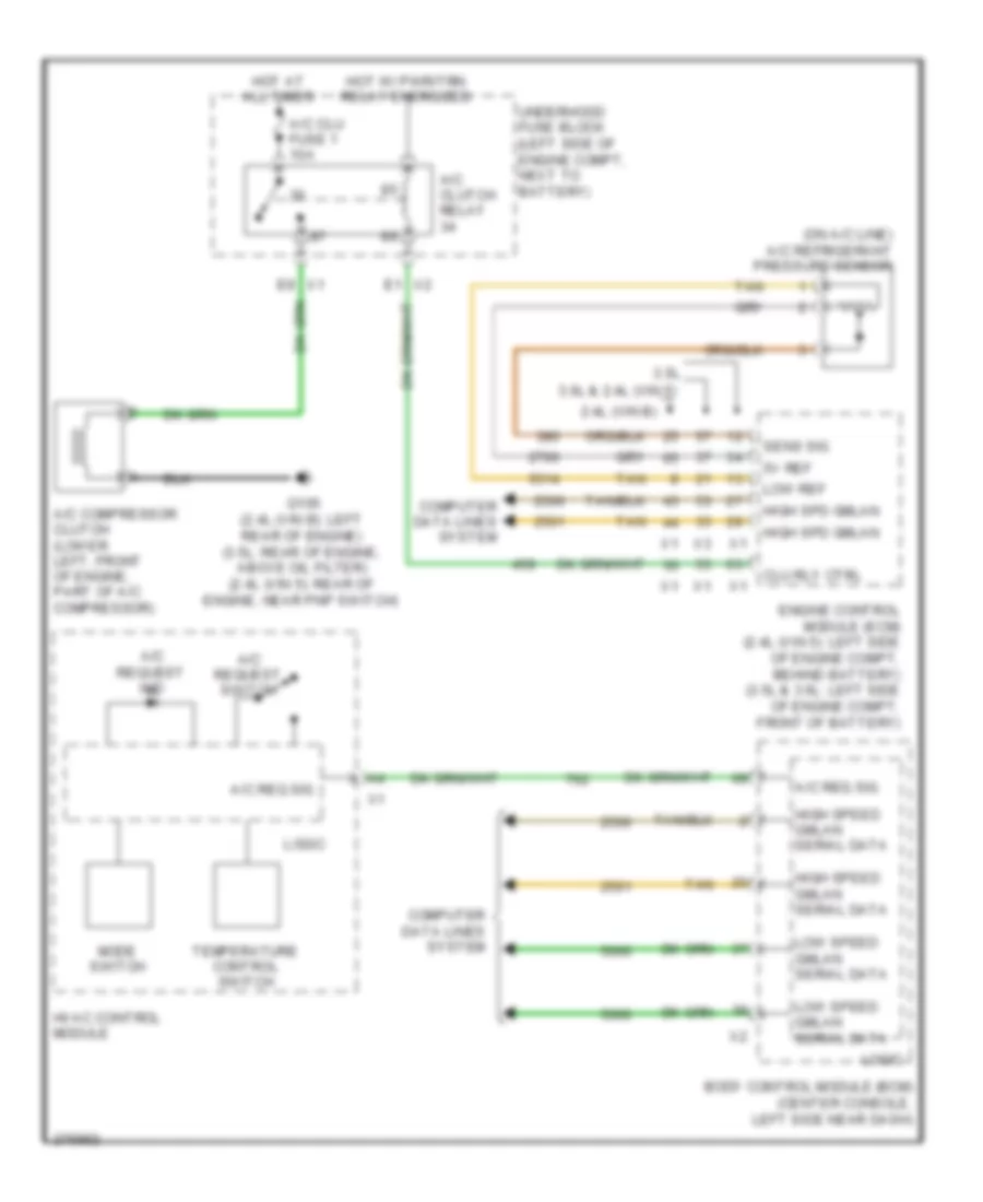
Compressor Wiring Diagram, with Manual A/C for Saturn Aura XR 2008
List of elements for Compressor Wiring Diagram, with Manual A/C for Saturn Aura XR 2008:
- (on a/c line) a/c refrigerant pressure sensor
- 2.4l (vin b)
- 3.5l
- 3.6l & 2.4l (vin 5)
- 5v ref
- A/c clu fuse 1 10a
- A/c clutch relay
- A/c compressor clutch (lower left, front of engine, part of a/c compressor)
- A/c req sig
- A/c request ind
- A/c request switch
- Body control module (bcm) (center console, left side near dash)
- Clu rly ctrl
- Computer data lines system
- E1 x2
- E8 x1
- Engine control module (ecm) (2.4l (vin 5): left side of engine compt, behind battery) (3.5l & 3.6l: left side of engine compt, front of battery)
- G106 (2.4l (vin b): left rear of engine) (3.5l: rear of engine, above oil filter) (2.4l (vin 5): rear of engine, near pnp switch)
- High spd gmlan
- High speed gmlan serial data
- Hot at all times
- Hot w/ pwr/trn relay energized
- Hvac control module
- Logic
- Low ref
- Low speed gmlan serial data
- Mode switch
- Sens sig
- Tan
- Temperature control switch
- Underhood fuse block (left side of engine compt, next to battery)
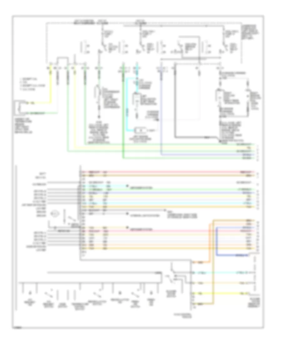
Manual A/C Wiring Diagram (1 of 2) for Saturn Aura XR 2008
List of elements for Manual A/C Wiring Diagram (1 of 2) for Saturn Aura XR 2008:
- (in engine harness) (2.4l (vin 5)) j150
- (in engine harness) (2.4l (vin 5)) j153
- 2.4l (vin b)
- 3.5l
- 5 volt ref
- 87a
- A/c clu fuse 1 10a
- A/c clutch relay
- A/c compressor clutch (lower left, front of engine, part of a/c compressor)
- A/c req sig
- A/c request ind
- A/c request switch
- A10
- A11
- A11 x2
- A12
- Air temp dr pos sig
- Ambient air temperature sensor (left front impact bar, behind grille)
- B10
- B10 x2
- B11
- B12
- Batt
- Blower motor resistor assembly
- Blower motor switch
- Cool fan 1 fuse 17 30a
- Cool fan 2 fuse 18 30a
- Cool/ fan 1 relay
- Cool/ fan 2 relay
- Cool/fan ser/par relay
- Defog ind
- Defog switch
- Defogger system
- Dr ctrl a
- Dr ctrl b
- E8 x1
- Except 2.4l (vin b)
- Except 3.5l
- F3 x1
- Fresh air ind
- Fresh air switch
- G106 (2.4l (vin b): left rear of engine) (3.5l: rear of engine, above oil filter) (2.4l (vin 5): rear of engine, near pnp switch)
- G201 (under dash, right side of console, near floor)
- Ground
- Hot at all times
- Hot w/ pwr/trn relay energized
- Hvac control module
- Ign 3 vol
- Interior lights system
- Left cooling fan (left rear of radiator)
- Left engine cooling fan diode (2.4l (vin 5))
- Logic
- Low ref
- Mode dr pos sig
- Mode switch
- Recirculation ind
- Recirculation switch
- Right cooling fan (right rear of radiator)
- Right engine cooling fan diode (2.4l (vin 5))
- Tan
- Temperature control switch
- Underhood fuse block (left side of engine compt, next to battery)
- X1 a2
- X1 e3
- X2 e1
- X3 b9
Manual A/C Wiring Diagram (2 of 2) for Saturn Aura XR 2008
List of elements for Manual A/C Wiring Diagram (2 of 2) for Saturn Aura XR 2008:
- 2.4l (vin b)
- 3.5l
- 3.6l & 2.4l (vin 5)
- 5v ref
- A/c refrigerant pressure sensor (on a/c line)
- A/c req sig
- After blow
- Air temperature actuator (center of hvac unit)
- Ambient air temp sens sig
- Blower motor (right side of hvac unit)
- Body control module (bcm) (center console, left side near dash)
- Clu rly ctrl
- Computer data lines system
- Data link connector (dlc) (lower left of dash)
- E3 x4
- Ect sens sig
- Engine control module (ecm) (2.4l (vin 5): left side of engine compt, behind battery) (3.5l & 3.6l: left side of engine compt, front of battery)
- Engine coolant temperature (ect) sensor (3.5l: in cylinder head, below coolant reservoir) (3.6l: left side of engine, behind generator) (2.4l: right side of engine, below camshaft position exhaust sensor)
- Except 3.6l 3.6l
- G203 (under dash, right side of console, near floor)
- Ground
- High spd gmlan
- High spd rly ctrl
- High speed gmlan serial data +
- High speed gmlan serial data -
- Hot at all times
- Hvac blower fuse 20a
- Hvac blower high relay
- Hvac ctrl (batt) fuse 10a
- Hvac ctrl (ign) fuse 10a
- Logic
- Low ref
- Low spd rly ctrl
- Low speed gmlan serial data
- Mode actuator (on left of hvac unit)
- Recirculation actuator (top right of hvac unit)
- Run relay
- Run rly ctrl
- Sens sig
- Tan

 Čeština
 Dansk
Dansk Deutsch
 Ελληνικά
 English
 Español
 Suomi
Suomi Français
 Français
 עברית
עברית Hrvatski
 Magyar
 Italiano
 日本語
日本語 한국어
한국어 Nederlands
 Polski
 Português
 Português
 Română
 Русский
 Slovenčina
 Slovenščina
 Svenska
 Türkçe
 中文 (中国)