ENGINE PERFORMANCE
2.5L
2.5L, Engine Performance Wiring Diagram (1 of 4) for Mazda 5 Grand Touring 2013
 https://portal-diagnostov.com/license.html
Automotive Electricians Portal FZCO
Automotive Electricians Portal FZCO
https://portal-diagnostov.com/license.html
https://portal-diagnostov.com/license.html
Automotive Electricians Portal FZCO
Automotive Electricians Portal FZCO
List of elements for 2.5L, Engine Performance Wiring Diagram (1 of 4) for Mazda 5 Grand Touring 2013:
- (top of brake pedal bracket) brake switch
- (under passenger's seat) g14
- 0140-101a
- 1aa
- 1ab
- 1ac
- 1ad
- 1ae
- 1af
- 1ag
- 1ah
- 1ai
- 1aj
- 1ak
- 1al
- 1am
- 1an
- 1ao
- 1ap
- 1aq
- 1ar
- 1as
- 1at
- 1au
- 1av
- 1aw
- 1ax
- 1ay
- 1az
- 1ba
- 1bb
- 1bc
- 1bd
- 1be
- 1bf
- 1bg
- 1bh
- Air conditioning system
- C-02
- C-04
- C-10
- C-11
- C-12
- C-18
- Clutch pedal position switch (m/t) (top of clutch pedal bracket)
- Computer data lines system
- Cooling fans system
- Cruise control system
- Exterior lights system
- Fuel tank pressure sensor (near fuel tank, in fuel line)
- G14 (under passenger's seat)
- G23 (left rear of engine)
- Hot at all times
- Nca
- Neutral switch (m/t) (left side of manual transaxle)
- Pcm (left rear of engine compt)
- Pnk
- Power distribution system
- Red
- Relay & fuse block (left rear of engine compt)
- Starting/charging system
- Stop fuse 10a
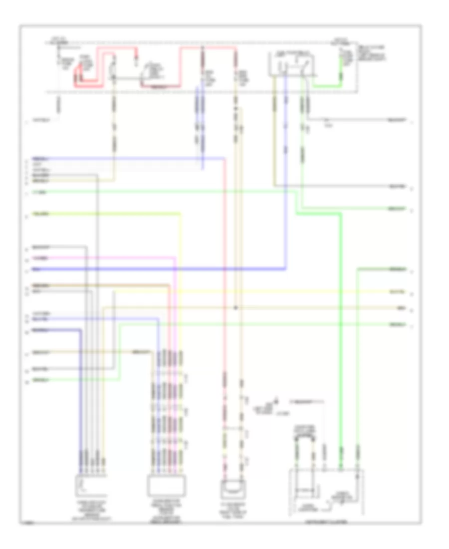
2.5L, Engine Performance Wiring Diagram (2 of 4) for Mazda 5 Grand Touring 2013
List of elements for 2.5L, Engine Performance Wiring Diagram (2 of 4) for Mazda 5 Grand Touring 2013:
- Accelerator pedal position sensor (top of accelerator pedal bracket)
- C-02
- C-04
- C-10
- C-11
- C-12
- C-13
- Check engine ind
- Computer data lines system
- Cv solenoid valve (right side of fuel tank)
- Eg1 main fuse 40a
- Eng bar fuse 15a
- Eng inj fuse 25a
- Eng+b fuse 10a
- Fuel pump fuse 20a
- Fuel pump relay
- G09 (left side of dash)
- Hot at all times
- Instrument cluster
- J/c g09
- Main relay (egi main 1)
- Mass air flow/ intake air temperature sensor (on air intake duct)
- Micro- computer
- Pnk
- Red
- Relay & fuse block (left rear of engine compt)
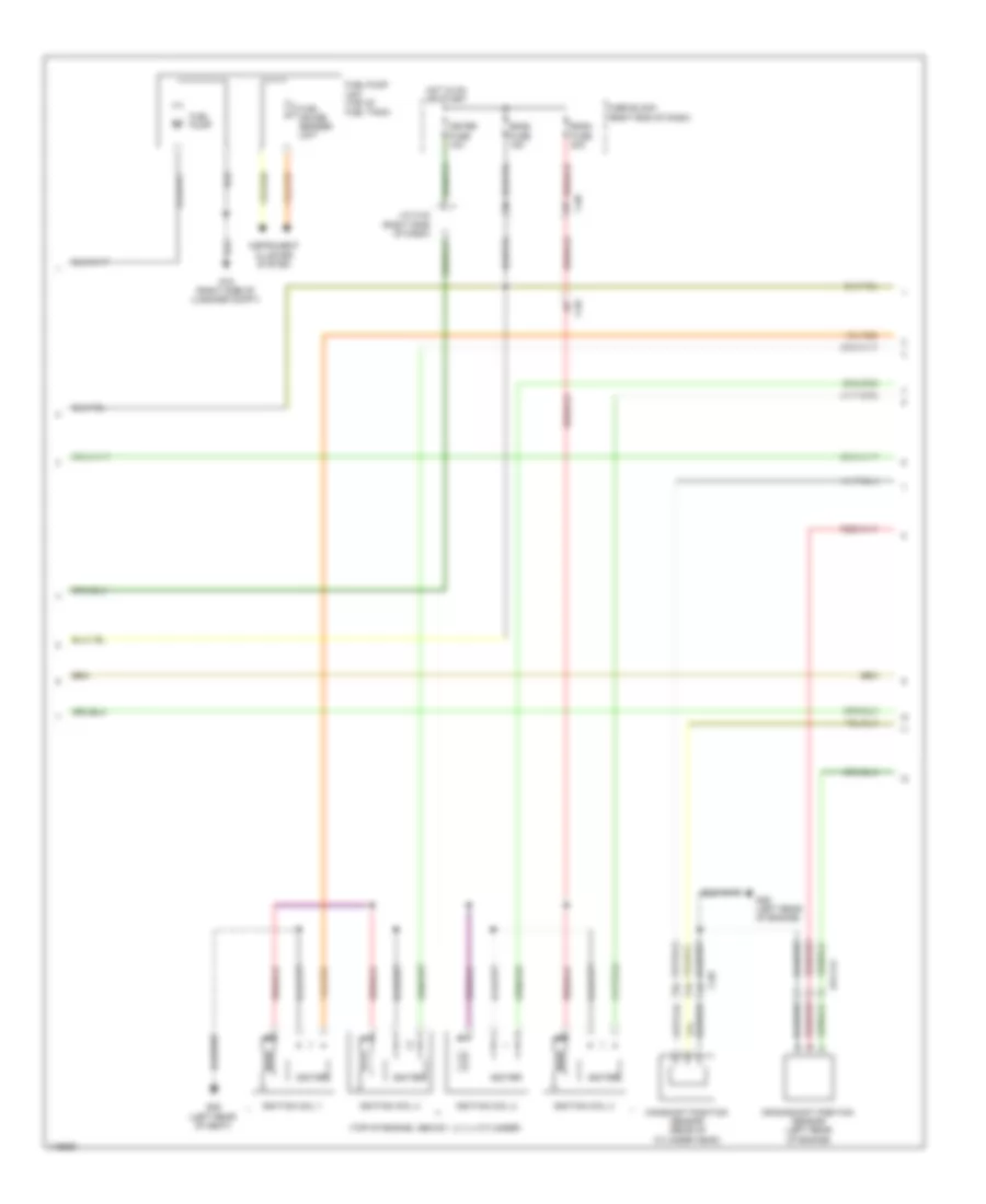
2.5L, Engine Performance Wiring Diagram (3 of 4) for Mazda 5 Grand Touring 2013
List of elements for 2.5L, Engine Performance Wiring Diagram (3 of 4) for Mazda 5 Grand Touring 2013:
- (top of engine, above 1, 2, 3, 4 cylinder)
- 014-141
- C-02
- C-05
- C-69
- Camshaft position sensor (rear of cylinder head)
- Crankshaft position sensor (left rear of engine)
- Eng2 fuse 15a
- Eng3 fuse 20a
- Fuel gauge sender unit
- Fuel pump
- Fuel pump unit (top of fuel tank)
- Fuse block (right end of dash)
- G15 (right side of luggage compt)
- G29 (left rear of engine)
- G29 (left rear of seat)
- Hot in on or start
- Igniter
- Ignition coil 1
- Ignition coil 2
- Ignition coil 3
- Ignition coil 4
- Instrument cluster system
- J/c c-42 (right side of dash)
- Meter fuse 10a
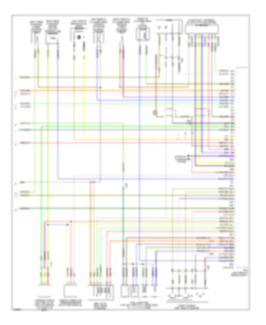
2.5L, Engine Performance Wiring Diagram (4 of 4) for Mazda 5 Grand Touring 2013
List of elements for 2.5L, Engine Performance Wiring Diagram (4 of 4) for Mazda 5 Grand Touring 2013:
- (front of cylinder head) oil control valve
- (in exhaust, upstream of catalytic converter) a/f sensor
- (left rear of cylinder head) variable intake air solenoid valve
- (left side of engine block) knock sensor
- (right rear of cylinder head) variable tumble solenoid valve
- (right rear of engine) engine coolant temperature sensor
- (right rear of engine) purge solenoid valve
- 0140-101b
- 0140-107a
- 0140-107b
- 2aa
- 2ab
- 2ac
- 2ad
- 2ae
- 2af
- 2ag
- 2ah
- 2ai
- 2aj
- 2ak
- 2al
- 2am
- 2an
- 2ao
- 2ap
- 2aq
- 2ar
- 2as
- 2at
- 2au
- 2av
- 2aw
- 2ax
- 2ay
- 2az
- 2ba
- 2bb
- 2bc
- 2bd
- 2be
- 2bf
- 2bg
- 2bh
- C-02
- C-14
- C-69
- Egr valve (right rear of engine)
- Fuel injectors (top left side of cylinder head, at 1, 2, 3, 4 cylinder)
- Ho2s
- Manifold absolute pressure sensor (on intake manifold)
- Nca
- Pcm (left rear of engine compt)
- Red
- Starting/ charging system
- Throttle body (left rear of engine)
- Variable tumble shutter valve position sensor (on throttle body)

 Čeština
 Dansk
Dansk Deutsch
 Ελληνικά
 English
 Español
 Suomi
Suomi Français
 Français
 עברית
עברית Hrvatski
 Magyar
 Italiano
 日本語
日本語 한국어
한국어 Nederlands
 Polski
 Português
 Português
 Română
 Русский
 Slovenčina
 Slovenščina
 Svenska
 Türkçe
 中文 (中国)