ANTI-LOCK BRAKES
Anti-lock Brake Wiring Diagrams for Volvo 850 1995
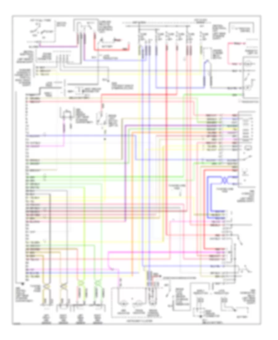
List of elements for Anti-lock Brake Wiring Diagrams for Volvo 850 1995:
- (below battery)
- (on brake fluid reservoir)
- A13
- A18
- A28
- A29
- Abs combination relay (left rear of engine compt)
- Abs control module (left rear of engine compartment)
- Abs hydraulic unit (left front engine compt)
- Abs indicator
- Abs pedal sensor (left rear of engine compartment)
- Acc
- Battery
- Body ground connector
- Brake fluid level sensor
- Brake light switch (below left i/p)
- Brake warning indicator
- Central electrical unit (left rear of engine compt)
- Control
- Early prod
- Early production
- Fuse 10a
- Fuse 15a
- Fuse 30a
- G111
- G111 (below battery)
- G205 (top right side of steering column)
- Hazard/ flasher relay switch
- Hot at all times
- Hot in acc or run
- Hot in run
- Ignition switch
- Instrument cluster
- Late prod
- Late production
- Left front abs sensor
- Left rear abs sensor
- Nca
- Off
- On-board diagnostic connector a (partial) (right front of engine compt)
- Overload relay #2 (in central electrical unit)
- Pnk
- Power ground connector
- Red
- Rheostat (left i/p)
- Right front abs sensor
- Right rear abs sensor
- Start
- Starting/charging system
- Tracs indicator
- Tracs switch
- Twisted wire pair
- Twisted wire pairs
- W/ traction
 Čeština
 Dansk
Dansk Deutsch
 Ελληνικά
 English
 Español
 Suomi
Suomi Français
 Français
 עברית
עברית Hrvatski
 Magyar
 Italiano
 日本語
日本語 한국어
한국어 Nederlands
 Polski
 Português
 Português
 Română
 Русский
 Slovenčina
 Slovenščina
 Svenska
 Türkçe
 中文 (中国)
 English