INSTRUMENT CLUSTER
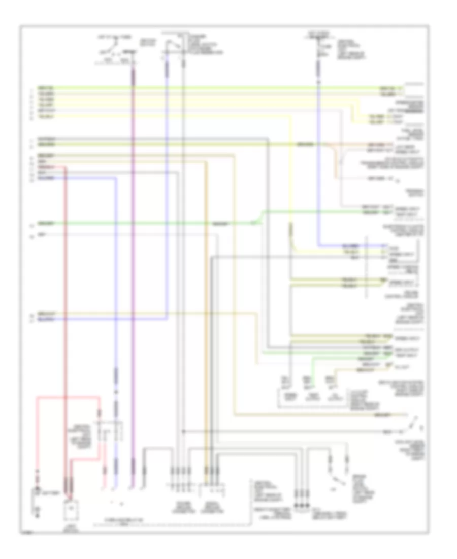
Instrument Cluster Wiring Diagram, VDO (1 of 2) for Volvo 850 1995

List of elements for Instrument Cluster Wiring Diagram, VDO (1 of 2) for Volvo 850 1995:
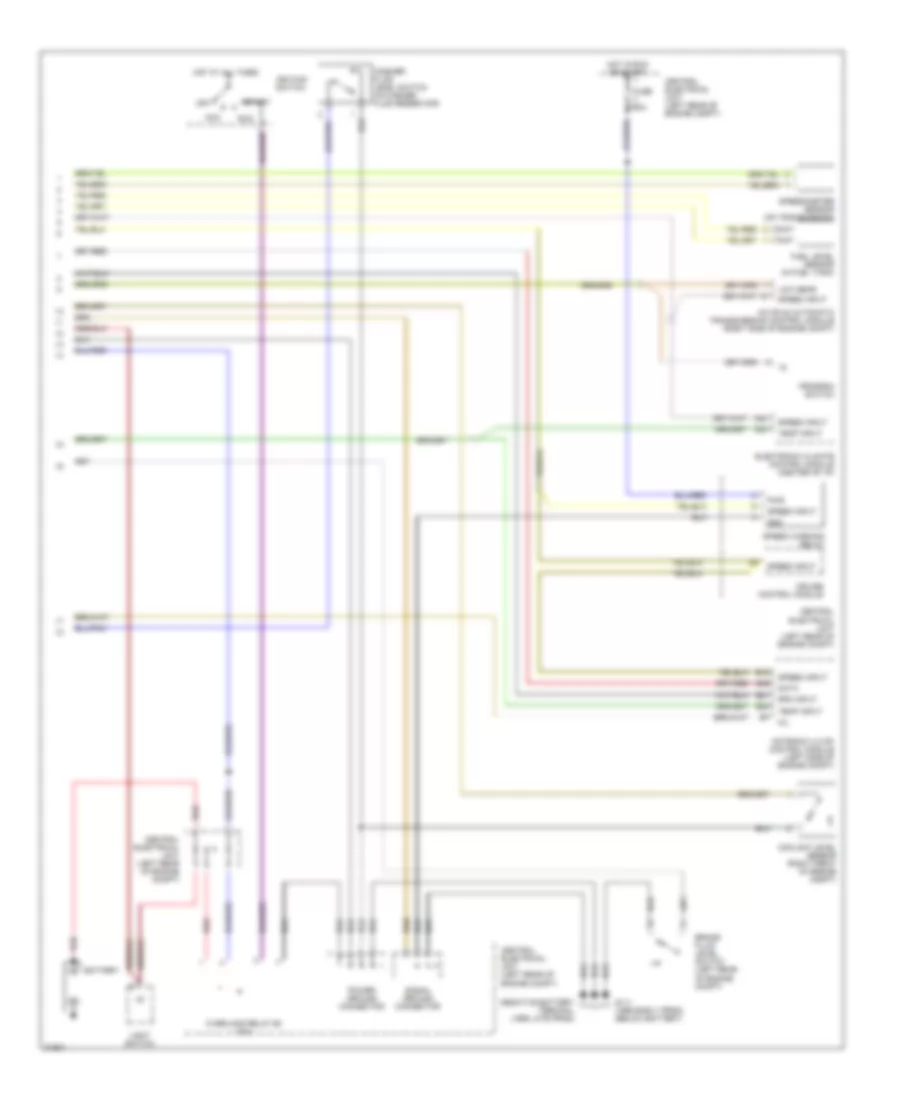
Instrument Cluster Wiring Diagram, VDO (2 of 2) for Volvo 850 1995
List of elements for Instrument Cluster Wiring Diagram, VDO (2 of 2) for Volvo 850 1995:
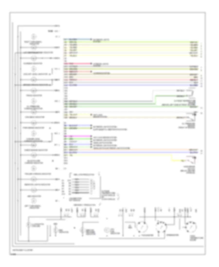
Instrument Cluster Wiring Diagram, Yasaki (1 of 2) for Volvo 850 1995
List of elements for Instrument Cluster Wiring Diagram, Yasaki (1 of 2) for Volvo 850 1995:
Instrument Cluster Wiring Diagram, Yasaki (2 of 2) for Volvo 850 1995
List of elements for Instrument Cluster Wiring Diagram, Yasaki (2 of 2) for Volvo 850 1995: