ANTI-THEFT
Forced Entry Wiring Diagram for Volvo V50 2007
 https://portal-diagnostov.com/license.html
Automotive Electricians Portal FZCO
Automotive Electricians Portal FZCO
https://portal-diagnostov.com/license.html
https://portal-diagnostov.com/license.html
Automotive Electricians Portal FZCO
Automotive Electricians Portal FZCO
List of elements for Forced Entry Wiring Diagram for Volvo V50 2007:
- (at left kick panel) g115
- (at right kick panel) g10
- (at right kick panel) g116
- (below driver's seat near rocker panel) g66
- (below passenger's seat near rocker panel) g67
- A11
- A12
- A15
- A18
- A28
- Ajar sw
- B28
- C21
- C24
- C27
- C31
- Ceiling light switch unit
- Central electronic module (cem) (behind right side of dash)
- Computer data lines system
- D10
- Driver's door lock unit (at rear of left front doors)
- Driver's door module (in driver's door)
- E21
- E22
- E36
- Engine compartment distribution box (left side of engine compt)
- F15
- F18
- F19
- F20
- F21
- F24
- F30
- Front mass movement sensor module (center of roof)
- Fuse 10a
- Fuse 25a
- Fuse 40a
- Fuse 60a
- G114 (on left front strut tower)
- G19
- G66 (below driver's seat near rocker panel)
- H17
- H19
- H21
- Hood alarm contact (at front of engine compt)
- Hot at all times
- Left rear door lock unit (at rear of left rear door)
- Left rear door module (in left rear door)
- Lock sw
- Passenger's door lock unit (at rear of right front door)
- Passenger's door module (in front passenger's door)
- Power window system
- Rear mass movement sensor (center rear of roof)
- Right rear door lock unit (at rear of right rear door)
- Right rear door module (in right rear door)
- Siren control module (scm) (at right rear of engine compt)
- Solar sensor taillight sensor & indicator alarm (on top center of dash)
- Trunk lid/ tailgate lock unit (center rear of trunk)
- V50
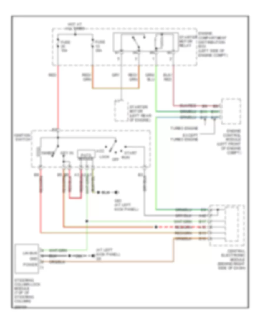
Immobilizer Wiring Diagram for Volvo V50 2007
List of elements for Immobilizer Wiring Diagram for Volvo V50 2007:
- (at left kick panel) g6
- A15
- A42
- Acc
- B10
- B11
- B13
- B17
- Central electronic module (behind right side of dash)
- Engine compartment distribution box (left side of engine compt)
- Engine control module (left front of engine compt)
- Except turbo engine
- Fuse 15a
- Fuse 30a
- G83 (at left kick panel)
- Gnd
- Hot at all times
- Ignition switch
- Inhibit
- Key in
- Lin bus
- Lock
- Off
- Pats module
- Power
- Red
- Run
- Start
- Starter motor (left rear of engine)
- Starter motor relay
- Steering column lock module (top of steering column)
- Turbo engine
 Čeština
 Dansk
Dansk Deutsch
 Ελληνικά
 English
 Español
 Suomi
Suomi Français
 Français
 עברית
עברית Hrvatski
 Magyar
 Italiano
 日本語
日本語 한국어
한국어 Nederlands
 Polski
 Português
 Português
 Română
 Русский
 Slovenčina
 Slovenščina
 Svenska
 Türkçe
 中文 (中国)
 English