HORN
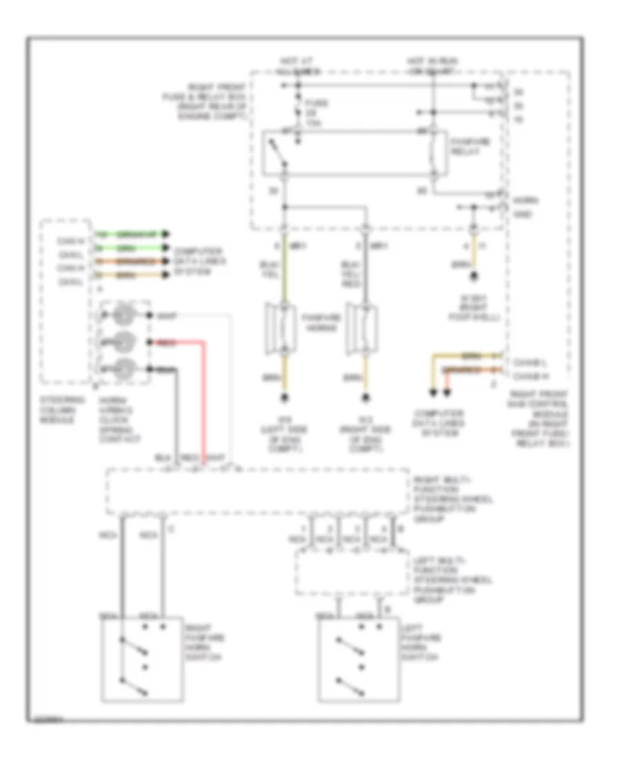
Horn Wiring Diagram for Mercedes-Benz S500 2005
List of elements for Horn Wiring Diagram for Mercedes-Benz S500 2005:
- Can h
- Can l
- Can-b h
- Can-b l
- Computer data lines system
- Fanfare horns
- Fanfare relay
- Fuse 15a
- Gnd
- Horn
- Horn/ airbag clock spring contact
- Hot at all times
- Hot in run or start
- Left fanfare horn switch
- Left multi- function steering wheel pushbutton group
- Mr1
- Nca
- Red
- Right fanfare horn switch
- Right front fuse & relay box (right rear of engine compt)
- Right front sam control module (in right front fuse/ relay box)
- Right multi- function steering wheel pushbutton group
- Steering column module
- W2 (right side of eng compt)
- W36/1 (right footwell)
- W9 (left side of eng compt)
 Čeština
 Dansk
Dansk Deutsch
 Ελληνικά
 English
 Español
 Suomi
Suomi Français
 Français
 עברית
עברית Hrvatski
 Magyar
 Italiano
 日本語
日本語 한국어
한국어 Nederlands
 Polski
 Português
 Português
 Română
 Русский
 Slovenčina
 Slovenščina
 Svenska
 Türkçe
 中文 (中国)
 English