STARTING/CHARGING
Charging Wiring Diagram for Chevrolet Camaro LS 2014
 https://portal-diagnostov.com/license.html
Automotive Electricians Portal FZCO
Automotive Electricians Portal FZCO
https://portal-diagnostov.com/license.html
https://portal-diagnostov.com/license.html
Automotive Electricians Portal FZCO
Automotive Electricians Portal FZCO
List of elements for Charging Wiring Diagram for Chevrolet Camaro LS 2014:
- (on battery positive (+) post) battery fuse block
- 3.6l
- 6.2l vin j/vin w & 7.0l
- 6.2l vin p
- Battery
- Battery cable junction block (on left front strut tower)
- Battery current sensor (on battery ground cable)
- Body control module (left side of dash)
- Charge ind
- Charge ind ctrl/ charge ind sig
- Computer data lines system
- Current sensor sig
- Current sensor voltage
- Driver information center display
- Engine control module (right front of engine compt)
- G401 (near battery)
- G403 (right front of luggage compt)
- Generator
- Generator field duty cycle signal
- Ground
- High speed gmlan serial data bus (+)
- High speed gmlan serial data bus (-)
- Instrument cluster
- Logic
- Low ref
- Low speed gmlan serial data
- Pnk
- Red
- Starter motor
- Starting circuit
- Tan
- X207
- X208
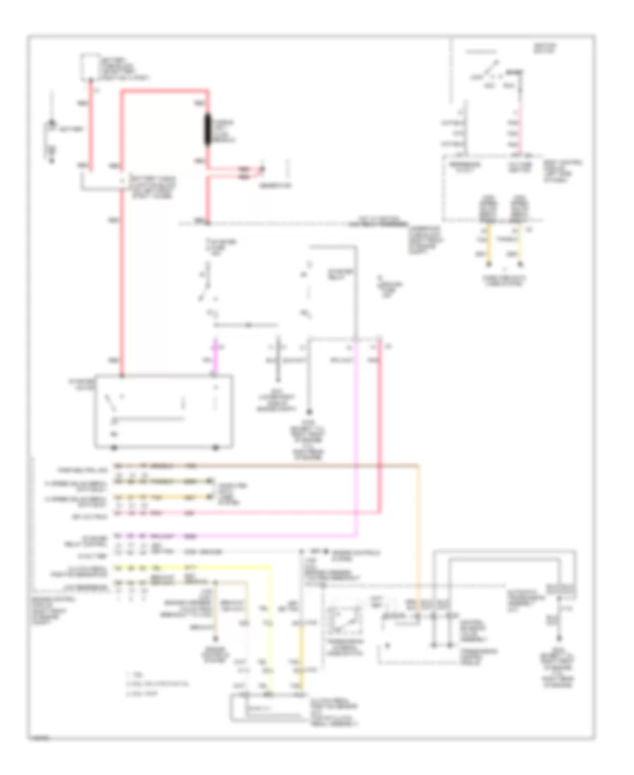
Starting Wiring Diagram for Chevrolet Camaro LS 2014
List of elements for Starting Wiring Diagram for Chevrolet Camaro LS 2014:
- (or 6109)
- (or 6110)
- 3.6l
- 5-volt ref
- 6.2l vin j/vin w & 7.0l
- 6.2l vin p
- Acc
- Automatic transmission assembly (a/t)
- Battery
- Battery cable junction block (on left front strut tower)
- Battery fuse block (on battery positive (+) post)
- Body control module (left side of dash)
- Clutch pedal position sensor (m/t) (top of clutch pedal assembly)
- Clutch pedal position sensor sig
- Computer data lines system
- Control solenoid valve assembly
- Ecm/ign fuse 15a
- Engine control module (right front of engine compt)
- Engine controls
- Engine controls system
- G101 (lower right side of engine compt)
- G106 (except 7.0l: right front of engine) (7.0l: right rear of engine)
- Generator
- Hi speed gmlan serial data bus +
- Hi speed gmlan serial data bus -
- High speed gmlan serial data +
- High speed gmlan serial data -
- Hot w/ ignition main relay energized
- Ign volt/run
- Ignition switch
- J108 (3.6l) (engine harness, 14.6 cm from breakout to x102)
- J109 (3.6l) (engine harness, 7 cm from breakout to x102)
- J118
- Lock
- Low reference
- Park/neutral sig
- Pnk
- Red
- Reference 5-volt
- Run
- Start
- Starter fuse 30a
- Starter motor
- Starter relay
- Starter relay control
- System
- Tan
- Transmission control module
- Transmission internal mode switch
- Underhood fuse block (right front of engine compt)
- Voltage ignition
- X102
- X104
- X2 f

 Čeština
 Dansk
Dansk Deutsch
 Ελληνικά
 English
 Español
 Suomi
Suomi Français
 Français
 עברית
עברית Hrvatski
 Magyar
 Italiano
 日本語
日本語 한국어
한국어 Nederlands
 Polski
 Português
 Português
 Română
 Русский
 Slovenčina
 Slovenščina
 Svenska
 Türkçe
 中文 (中国)