
 Čeština
 Dansk
Dansk Deutsch
 Ελληνικά
 English
 Español
 Suomi
Suomi Français
 Français
 עברית
עברית Hrvatski
 Magyar
 Italiano
 日本語
日本語 한국어
한국어 Nederlands
 Polski
 Português
 Português
 Română
 Русский
 Slovenčina
 Slovenščina
 Svenska
 Türkçe
 中文 (中国)

Jeep Cherokee Sport 1991 - 1991 ENGINE PERFORMANCE Self-Diagnostics
Jeep Cherokee Sport 1991 - INTRODUCTION
If no faults were found while performing BASIC DIAGNOSTIC PROCEDURES in the BASIC TESTING article, proceed with self-diagnostics. If no fault codes or only pass codes are present after entering self-diagnostics, proceed to appropriate TESTS W/O CODES article for diagnosis by symptom (i.e. ROUGH IDLE, NO START, etc.).
Jeep Cherokee Sport 1991 - MODEL IDENTIFICATION
Jeep Cherokee Sport 1991 VEHICLE BODY IDENTIFICATION
Model Name Body Type Cherokee XJ Comanche MJ Wrangler YJ
Jeep Cherokee Sport 1991 - SELF-DIAGNOSTIC SYSTEM SYSTEM DIAGNOSIS
Self-diagnostic capabilities of this system, if properly utilized, can simplify testing. Single Board Engine Controller II (SBEC-II) monitors several different engine control system circuits.
If a problem is sensed with a monitored circuit, a fault code is stored in SBEC-II, CHECK ENGINE light illuminates and SBEC-II enters limp-in mode. In limp-in mode, SBEC compensates for component failure by substituting information from other sources, allowing vehicle operation until repairs can be made.
Once codes are known, refer to FAULT CODES to determine questionable circuit. Test circuits, and repair or replace components as required. If problem is repaired or ceases to exist, SBEC-II cancels fault code after 50 ignition on/off cycles. To clear codes, refer to CLEARING TROUBLE CODES .
A specific fault code results from a particular system failure. It is NOT necessarily reason for failure. Fault code does not condemn a specific component, but calls out a probable malfunction area.
Jeep Cherokee Sport 1991 - HARD FAILURES
Hard failures cause CHECK ENGINE light to illuminate and remain on until the malfunction is repaired. If light comes on and remains on (light may flash) during vehicle operation, cause of malfunction must be determined using diagnostic (code) charts. If a sensor fails, SBEC-II will use a substitute value in its calculations, allowing engine operation in limp-in mode. In this condition, vehicle will run but driveability may be poor.
Jeep Cherokee Sport 1991 - INTERMITTENT FAILURES
Intermittent failures may cause CHECK ENGINE light to flicker or stay on until the intermittent fault goes away. However, the corresponding trouble code will be retained in SBEC-II memory. If related fault does not reoccur within a certain time frame, related trouble code will be erased from SBEC-II memory. Intermittent failures can be caused by faulty sensor, bad connector or wiring related problems. See INTERMITTENTS in TESTS W/O CODES article.
Jeep Cherokee Sport 1991 - DIAGNOSTIC PROCEDURE
- ENTERING ON-BOARD DIAGNOSTICS to obtain fault codes. If fault codes are NOT present and/or DRB-II (Diagnostic Readout Box-II) is used, proceed to one of the following tests:
- Go to NO START TEST 1A (NS-1A ) if a no-start condition exists or engine stalls after start-up. Perform indicated VERIFICATION PROCEDURE after repairs. Ensure charts apply to engine being tested.
- - DRB-II FAULT MESSAGES table if engine runs but has performance problems. Perform indicated VERIFICATION PROCEDURE after repairs. Ensure charts apply to engine being tested.
NOTE: When using trouble shooting charts for diagnosis, DO NOT skip any steps in chart or incorrect diagnosis may result.
Before proceeding with diagnosis, the following precautions must be followed:
- Vehicle must have a fully charged battery and functional charging system.
- Probe SBEC-II connector from pin side. DO NOT backprobe SBEC-II connector.
- DO NOT cause short circuits when performing electrical tests. This will set additional fault codes, making diagnosis of original problem more difficult.
- DO NOT use a test light in place of a voltmeter.
- When checking for spark, ensure coil wire is NO more than 1/4" from ground. If coil wire is more than 1/4" from ground, damage to vehicle electronics and/or SBEC-II may result.
- DO NOT prolong testing of fuel injectors or engine may hydrostatically (liquid) lock.
- Always repair lowest fault code number (CHECK ENGINE light) or first fault displayed (DRB-II) first.
- Always perform indicated VERIFICATION PROCEDURE after repairs.
- Always disconnect DRB-II after use.
- Always disconnect DRB-II before charging battery.
Jeep Cherokee Sport 1991 - ENTERING ON-BOARD DIAGNOSTICS
NOTE: Manufacturer recommends using DRB-II (Diagnostic Readout Box-II) to diagnose the system. See DRB-II TEST FUNCTIONS for complete diagnostic instructions.
Jeep Cherokee Sport 1991 - Obtaining Fault Codes
- Ensure ignition is off. Attach DRB-II to engine diagnostic connector. Connector is located on left side of engine compartment, near SBEC-II. See Fig. 1 . Start engine (if possible). Turn A/C switch on, then off (if equipped).
- Turn engine off. Without starting engine, turn ignition on and access READ FAULTS function of DRB-II FUEL/IGN MENU. See DRB-II DIAGNOSTIC MODE under DRB-II TEST FUNCTIONS if necessary.
- Record all fault messages displayed by DRB-II, and observe CHECK ENGINE light on instrument cluster. CHECK ENGINE light should come on for 3 seconds and then go out (bulb check).


Fig. 1: Jeep Cherokee Sport 1991 - Component Locations - Locating Diagnostic Connector
Jeep Cherokee Sport 1991 - CLEARING TROUBLE CODES
- To clear trouble codes, ensure ignition is off. Connect DRB-II to engine diagnostic connector. Connector is located on left side of engine compartment, near SBEC-II. See Fig. 1 . Turn ignition switch to RUN position.
- The copyright information and diagnostic program version will appear on screen for a few seconds. After a few seconds DRB-II menu will appear. At FUEL/IGN menu, press "5" (ADJUSTMENTS) key. Press ENTER key. At ADJUSTMENTS menu, press "1" (ERASE FAULTS) key. Press ENTER key.
- The DRB-II will display ERASE FAULTS ARE YOU SURE? (ENTER TO ERASE). Press ENTER key. When DRB-II is finished erasing fault codes, screen will display ERASE FAULTS, FAULTS ERASED.
Jeep Cherokee Sport 1991 - FAULT CODE TABLE
Jeep Cherokee Sport 1991 FAULT CODE
Code Display On DRB-II (1) Fault Condition 11 IGN REFERENCE SIGNAL No Distributor Reference Signal Detected During Cranking 13(2) (3) SLOW CHANGE IN MAP SIGNAL No Difference In MAP Sensor Signal Is Detected 13 NO CHANGE IN MAP FROM START TO RUN No Difference Detected Between MAP & Barometric Pressure Readings 14(2) (3) MAP VOLTAGE TOO LOW MAP Sensor Input Below Minimum Acceptable Voltage 14 MAP VOLTAGE TOO HIGH MAP Sensor Input Above Maximum Acceptable Voltage 15(3) NO VEHICLE SPEED SIGNAL No Distance Sensor Signal Detected With Road Load Conditions 17 ENGINE IS COLD TOO LONG Coolant Temp. Stays Below Normal Operating Temp. During Vehicle Operation 21(3) O2 SIGNAL STAYS AT CENTER Neither Rich Nor Lean Condition Is Detected From Oxygen Sensor Input 21 O2 SENSOR SHORTED TO VOLTAGE O2 Sensor Input Voltage Maintained Above Normal Operating Range 22(2) (3) COOLANT SENSOR VOLTAGE TOO LOW Coolant Temp. Sensor Input Below Minimum Acceptable Voltage 22 COOLANT SENSOR VOLTAGE TOO HIGH Coolant Temp. Sensor Input Above Maximum Acceptable Voltage 23(2) (3) CHARGE TEMP SENSOR VOLTAGE LOW Charge Temp. Sensor Input Below Minimum Acceptable Voltage 23 CHARGE TEMP SENSOR VOLTAGE HIGH Charge Temp. Sensor Input Above Maximum Acceptable Voltage 24(2) (3) TPS VOLTAGE LOW TPS Sensor Output Less Than Minimum Acceptable Voltage 24 TPS VOLTAGE HIGH TPS Sensor Output More Than Maximum Acceptable Voltage 25(3) AUTOMATIC IDLE SPEED MOTOR CIRCUITS Short/Open Circuit Detected In One Or More Automatic Idle Speed (AIS) Motor Circuits 27(2) (3) INJECTOR (#) CONTROL CIRCUIT Injector (Number) Output Driver Does Not Respond Correctly To SBEC Control Signal 33 A/C CLUTCH RELAY CIRCUIT Open/Short Condition Detected In A/C Clutch Relay Circuit 34(4) SPEED CONTROL SOLENOID CIRCUITS Open/Short Condition Detected In Speed (Cruise) Control Vacuum Or Vent Solenoid Circuits 35(4) RADIATOR FAN RELAY Open Or Shorted Condition Detected In Radiator Fan Relay Circuit 41(2) (3) ALTERNATOR FIELD NOT SWITCHING PROPERLY Open/Short Condition Detected In Alternator Field Circuit 42 ASD RELAY CIRCUIT Open/Short Condition Detected In ASD Relay Circuit 42 NO ASD RELAY VOLTAGE SENSED AT CONTROLLER No ASD Relay Voltage Sensed At SBEC Controller 44 BATTERY TEMP SENSOR VOLTAGE OUT OF LIMITS Battery Temp. Sensor Voltage Out Of Limit 46(2) (3) CHARGING SYSTEM VOLTAGE TOO HIGH Charging System Voltage Too High 47(2) (3) CHARGING SYSTEM VOLTAGE TOO LOW Charging System Voltage Too Low 51(3) O2 SIGNAL STAYS BELOW CENTER (LEAN) O2 Sensor Signal Stays Lean 52(3) O2 SIGNAL STAYS ABOVE CENTER (RICH) O2 Sensor Signal Stays Rich 53 INTERNAL CONTROLLER FAILURE Internal Engine Controller Fault Condition Detected 53 CONTROLLER FAILURE SPI COMMUNICATIONS No Internal Communication Between Co-Processors 54 NO SYNC PICK-UP SIGNAL No Synchronization Pick-Up Signal 55 NO DISPLAY (BLANK) Completion Of Fault Code Display By CHECK ENGINE Light 62 CONTROLLER FAILURE (EMR MILES NOT STORED) Engine Controller Failure, EMR Miles Not Stored 63 CONTROLLER FAILURE EEPROM WRITE DENIED Engine Controller Failure, EEPROM Write Denied 76(4) FUEL PUMP RESISTOR BYPASS RELAY CIRCUIT Open/Short Detected In The Ballast Resistor By-Pass Circuit
(1) Actual message displayed on DRB-II.
(2) CHECK ENGINE light on.
(3) CHECK ENGINE light on (California only).
(4) Comanche and Cherokee only.
Jeep Cherokee Sport 1991 - DRB-II TEST FUNCTIONS
NOTE: DO NOT touch DRB-II keypad during DRB-II power-up sequence or an error message will result. If DRB-II screen is blank or any error messages appear, refer to DRB-II PROBLEMS & ERROR MESSAGES .
Jeep Cherokee Sport 1991 - DRB-II Diagnostic Mode
- In order to perform diagnostic tests using DRB-II, DRB-II must be in FUEL/IGN MENU. At FUEL/IGN MENU, fault codes and DRB-II test functions can be accessed.
- To reach FUEL/IGN MENU, ensure ignition is off. Connect DRB-II to engine diagnostic connector. Connector is located on left side of engine compartment, near SBEC-II. See Fig. 1 . Turn ignition switch to RUN position.
- Copyright information and diagnostic program version will appear on screen for a few seconds. After a few seconds DRB-II menu will appear. At DRB-II menu, press "4" (SELECT SYSTEM) key. Press ENTER key.
- At SELECT SYSTEM menu, press "1" (ENGINE) key. Press ENTER key. The DRB-II menu will appear indicating engine year, size, type of transmission and SBEC-II part number.
- After a few seconds AIR COND menu will appear. Press "1" (WITH A/C) or press "2" (WITHOUT A/C). Press ENTER key. The DRB-II display will change to ENGINE SYSTEMS menu. At ENGINE SYSTEMS menu, press "1" (FUEL/IGNITION) key. Press ENTER key.
- Display will change to FUEL/IGN MENU. At FUEL/IGN menu of engine diagnostic program, specific test functions programmed into DRB-II can be performed. Following DRB-II modes can be accessed: SYSTEM TEST, READ FAULTS, STATE DISPLAY, ACTUATOR TEST and ADJUSTMENTS.
Jeep Cherokee Sport 1991 - System Test Mode
This function is not available in the engine diagnostics program.
Jeep Cherokee Sport 1991 - Read Faults Mode
This function allows the user to read and erase fault codes. A fault counter will appear along with fault displayed on DRB-II. As an example, DRB-II will display 1 OF 2 FAULTS. SBEC-II will store up to 8 fault messages. Faults are numbered in reverse order of setting. The most recent fault to occur will be number one. Vehicles without air conditioning will always have A/C CLUTCH RELAY CKT (circuit) stored in memory. This fault will always be number one if vehicle is not equipped with A/C. If no fault messages are stored, DRB-II will display NO FAULTS DETECTED and start counter will show 0 STARTS SINCE ERS (Erased).
A start counter will appear below DRB-II fault counter display. Start counter counts the number of times vehicle is started since faults were last set, erased, or battery was disconnected. This helps determine if fault is intermittent. Memory space limits start counter to first 3 faults. Start counter of zero equals a hard fault. Start counter of more than zero indicates an intermittent fault. Start counter will count up to 255 starts. If no fault messages are stored, DRB-II will display NO FAULTS DETECTED and start counter will show 0 STARTS SINCE ERS (Erased).
Jeep Cherokee Sport 1991 - State Display Mode
This function allows user to read states or values of a variety of sensors, inputs/outputs and components. The SBEC-II can only recognize high and low states on switch circuits. The SBEC-II cannot tell difference between an open or short circuit or a defective switch. If DRB-II displays a change between INPUT HIGH and INPUT LOW, it can be assumed entire switch circuit to SBEC-II is functioning.
Jeep Cherokee Sport 1991 - Actuator Test Mode
This function allows the user to check for proper operation of output circuits or devices, which the SBEC-II cannot internally recognize. DRB-II allows SBEC-II to activate these outputs or devices, allowing an observer to verify proper operation.
Most tests available in this mode provide an audible or visual indication of device operation (click of relay contacts, spray fuel, etc.). With the exception of an intermittent condition, if a device functions properly during its test, it can be assumed device, wiring and its driver circuit are functioning properly.
Jeep Cherokee Sport 1991 - Adjustments Mode
This function allows user to erase fault codes. Function also allows user to perform Emission Maintenance Reminder (EMR) memory test and reset Emission Maintenance Reminder (EMR) light and mileage.
Jeep Cherokee Sport 1991 - DRB-II Volt/Ohmmeter Mode
- To access volt/ohmmeter mode of DRB-II, connect Red volt/ohmmeter test lead to Red port, located on top right side of DRB-II.
NOTE: Because DRB-II is grounded through engine diagnostic connector, only one volt/ohmmeter test lead is required when using volt/ohmmeter option. The DRB-II volt/ohmmeter mode should only be used when diagnostic flow charts require the use of this option. - To access voltmeter, press VOLT/OHM key once. DRB-II is now in voltmeter mode. Touch test probe to connector or wire to be measured. Read voltage on DRB-II display. When voltage testing is completed, press VOLT/OHM key 3 times to exit voltmeter mode.
- To access ohmmeter, press VOLT/OHM key twice. DRB-II is now in ohmmeter mode. Touch test probe to connector or wire to be measured. Read resistance to circuit ground on DRB-II display. When resistance testing is complete, press VOLT/OHM key twice to exit ohmmeter mode.
Jeep Cherokee Sport 1991 - DRB-II Continuity Meter Mode
To access continuity meter, press VOLT/OHM key 3 times. Display will read NO CONTINUITY. Touch test probe to connector or wire to be measured. Read continuity on DRB-II display. When continuity testing is complete, press VOLT/OHM key once to exit continuity meter mode.
Jeep Cherokee Sport 1991 - Vehicles Tested Mode
- Vehicles tested mode is used to show what vehicles are covered by DRB-II cartridge. To access vehicles tested mode, ensure ignition is off.
- Connect DRB-II to engine diagnostic connector. Connector is located on left side of engine compartment, near SBEC-II. See Fig. 1 . Turn ignition switch to RUN position.
- The copyright information and diagnostic program version will appear on screen for a few seconds. After a few seconds DRB-II menu will appear. At DRB-II menu, press "1" (VEHICLES TESTED) key. Press ENTER key. DRB-II will display vehicles covered by cartridge. Screen will display for 5 seconds and return to DRB-II menu.
Jeep Cherokee Sport 1991 - How To Use Mode
- To access how to use mode, ensure ignition is off. Attach DRB-II to engine diagnostic connector. Connector is located on left side of engine compartment, near SBEC-II. See Fig. 1 . Turn ignition switch to RUN position.
- The copyright information and diagnostic program version will appear on screen for a few seconds. After a few seconds DRB-II menu will appear. At DRB-II menu, press "2" (HOW TO USE) key. Press ENTER key. A series of screens will be displayed explaining use of DRB-II keys used to move through engine diagnostic program.
Jeep Cherokee Sport 1991 - Configure Mode
- Configure option allows user to VIEW or CHANGE DRB-II display to US/METRIC, KEY CLICK, KEY REPEAT, or REMOTE DISPLAY. All selections made under CONFIGURE option remain active until user changes selection.
- To access how to use mode, ensure ignition is off. Attach DRB-II to engine diagnostic connector. Connector is located on left side of engine compartment, near SBEC-II. See Fig. 1 . Turn ignition switch to RUN position.
- The copyright information and diagnostic program version will appear on screen for a few seconds. After a few seconds DRB-II menu will appear. At DRB-II menu, press "3" (CONFIGURE) key. Press ENTER key. DRB-II will display CONFIGURE menu.
- Selecting VIEW from CONFIGURE menu allows user to view setting of CONFIGURE functions. Selecting CHANGE from CONFIGURE menu allows user to change setting of CONFIGURE functions.
- Selecting US/METRIC function allows user to have sensor, input/output values displayed in either US/METRIC units. Selecting KEY CLICK allows user to have a Green light come on or have a beeper sound whenever a DRB-II key is pressed.
- If REPEAT KEY function is on, the down/up arrow key will scroll the DRB-II display repeatedly. If REPEAT KEY function is off, the down/up arrow will scroll the DRB-II display only one item at a time. Selecting REMOTE DISPLAY function allows user to have DRB-II screen displayed on another screen.
Jeep Cherokee Sport 1991 - DRB-II PROBLEMS & ERROR MESSAGES Blank DRB-II Message Screen
- Connect DRB-II to a different vehicle. If message screen is still blank, DRB-II or cable adapter are faulty. Substitute to find faulty component.
- If message screen is not blank, DRB-II and cable adapter are functioning properly. Inspect diagnostic connector for proper wire placement, damaged terminals or pushed out pins. Repair as necessary.
- If diagnostic connector is okay, use an ohmmeter to check resistance between Black/White or Black/Yellow wire and ground at engine diagnostic connector. If resistance is 10 ohms or more, repair open in Black/White or Black/Yellow wire.
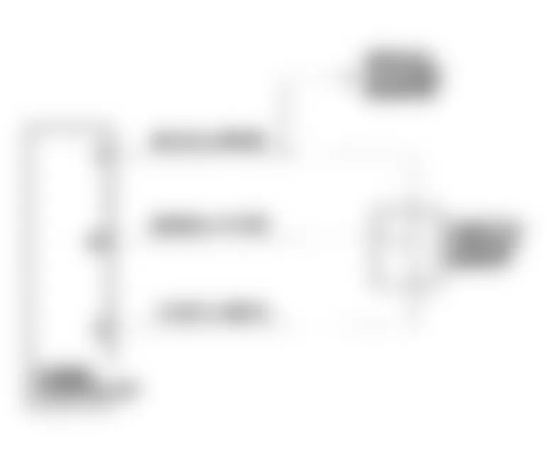
Jeep Cherokee Sport 1991 - No Response Message
- Ensure ignition is OFF and disconnect DRB-II. Using an external ohmmeter, check resistance of Pink or Black/Red wire between SBEC-II pin No. 25 and engine diagnostic connector. See Fig. 2 . If resistance is 10 ohms or more, repair open in Pink or Black/Red wire.
- If resistance is less than 10 ohms, check resistance of Light Green or Black/Pink wire between SBEC-II pin No. 45 and engine diagnostic connector. If resistance is 10 ohms or more, repair open in Light Green/Orange or Black/Pink wire.
- If resistance is less than 10 ohms, turn ignition off and disconnect DRB-II, DRB-II cartridge, and adapter cable. Find a second vehicle identical in equipment to vehicle being tested.
- Connect DRB-II to substitute (second) vehicle and use DRB-II as you did on original vehicle. If message screen is still blank, adapter cable or DRB-II (including cartridge) is faulty. Substitute adapter cable with a known good cable to find faulty component.
- If message screen is NOT blank, DRB-II and cable adapter are functioning properly. Inspect diagnostic connector on original vehicle for proper wire placement, corrosion, damaged terminals, or pushed-out pins. Repair as necessary.
Jeep Cherokee Sport 1991 - Ram Test Failure Message
Replace DRB-II.
Jeep Cherokee Sport 1991 - Cartridge Error Message
Replace DRB-II cartridge.
Jeep Cherokee Sport 1991 - Key Pad Test Failure Message
Power up DRB-II again with fingers off the keypad. If error message returns, replace DRB-II.
Jeep Cherokee Sport 1991 - High Or Low Battery Message
Correct condition of vehicle battery and reconnect DRB-II.
Fig. 2: Jeep Cherokee Sport 1991 - Component Locations - Testing For NO RESPONSE Message
Jeep Cherokee Sport 1991 - EMISSION MAINTENANCE REMINDER (EMR) MEMORY TEST
NOTE: Perform EMR memory test only if referred here by flow charts.
- To perform EMR memory check, ensure ignition is off. Attach DRB-II to engine diagnostic connector. Connector is located on left side of engine compartment, near SBEC-II. See Fig. 1 . Turn ignition switch to RUN position.
- Copyright information and diagnostic program version will appear on screen for a few seconds. After a few seconds DRB-II menu will appear. At FUEL/IGN menu, press "5" (ADJUSTMENTS) key. Press ENTER key. At ADJUSTMENTS menu, press "4" (EMR MEMORY CHK) key. Press ENTER key. The DRB-II display will read EMR MEMORY CHECK ARE YOU SURE? (ENTER TO CONTINUE).
- Press ENTER key. The DRB-II will display EMR MEMORY TEST WRITE TEST [-------] and after a few seconds IS INSTRUMENT PANEL MILEAGE BETWEEN XXXXX AND XXXXX? (PRESS YES OR NO). If vehicle mileage is within specification, EMR memory check is complete. Press YES key. If vehicle mileage is not within specification, go to next step.
- Press NO key. DRB-II will display ENTER MILEAGE SHOWN ON INSTRUMENT PANEL (USE ENTER KEY TO END) XXXXXXX. Enter vehicle mileage. DO NOT enter tenths. When correct vehicle mileage is entered, press ENTER key.
- DRB-II will ask for verification of mileage entry. If mileage entry was accurate, press ENTER key. DRB-II will display EMR MEMORY CHECK COMPLETE. Vehicle must travel at least 8 miles for reset to occur.
Jeep Cherokee Sport 1991 - EMISSION MAINTENANCE REMINDER (EMR) LIGHT RESET PROCEDURE
Emission Maintenance Reminder (EMR) light is designed to be a reminder to service vehicle emissions control system. It is not an emissions warning system, only a reminder to perform necessary emissions servicing.
Components to be serviced include PCV valve, oxygen sensor and some vacuum-operated components. EMR light will illuminate after a predetermined mileage.
- To reset EMR light, ensure ignition is off. Connect DRB-II to engine diagnostic connector. Connector is located on left side of engine compartment, near SBEC-II. See Fig. 1 . Turn ignition switch to RUN position.
- Copyright information and diagnostic program version will appear on screen for a few seconds. After a few seconds DRB-II menu will appear. At FUEL/IGN menu, press "5" (ADJUSTMENTS) key. Press ENTER key.
- At ADJUSTMENTS menu, press "3" (RESET EMR LIGHT) key. Press ENTER key. Display will read RESET EMR LIGHT ARE YOU SURE? (ENTER TO RESET). Press ENTER key.
Jeep Cherokee Sport 1991 - EMISSION MAINTENANCE REMINDER (EMR) MILEAGE TRANSFER
NOTE: Perform mileage transfer procedure only if SBEC-II is being replaced.
- When SBEC-II is replaced, vehicle mileage must be copied from odometer to replacement SBEC-II memory. Transfer of vehicle mileage will enable new SBEC-II to operate EMR light properly.
- To transfer mileage to SBEC-II, ensure ignition is off. Connect DRB-II to engine diagnostic connector. Connector is located on left side of engine compartment, near SBEC-II. See Fig. 1 . Turn ignition switch to RUN position.
- Copyright information and diagnostic program version will appear on screen for a few seconds. After a few seconds DRB-II menu will appear. At FUEL/IGN menu, press "5" (ADJUSTMENTS) key. Press ENTER key. At ADJUSTMENTS menu, press "4" (EMR MEMORY CHK) key. Press ENTER key. The DRB-II display will read EMR MEMORY CHECK ARE YOU SURE? (ENTER TO CONTINUE).
- Press ENTER key. The DRB-II will display EMR MEMORY TEST WRITE TEST [-------] and after a few seconds IS INSTRUMENT PANEL MILEAGE BETWEEN XXXXX AND XXXXX? (PRESS YES OR NO). If vehicle mileage is within specification, EMR memory check is complete. Press YES key. If vehicle mileage is not within specification, go to next step.
- Press NO key. DRB-II will display ENTER MILEAGE SHOWN ON INSTRUMENT PANEL (USE ENTER KEY TO END) XXXXXXX. Enter vehicle mileage. DO NOT enter tenths. When correct vehicle mileage is entered, press ENTER key.
- DRB-II will ask for verification of mileage entry. If mileage entry was accurate, press ENTER key. DRB-II will display EMR MEMORY CHECK COMPLETE. Vehicle must travel at least 8 miles for reset to occur.
Jeep Cherokee Sport 1991 - THEFT ALARM TEST CHEROKEE
NOTE: If SECURITY light comes and remains on with ignition on, the Chrysler Collision Detection (CCD) bus communication with the engine controller has been lost. After servicing vehicle ensure that system operates properly. A malfunctioning anti-theft system may keep engine from starting.
- Turn ignition switch to ACCY position 3 times and leave in ACCY position to activate Security Alarm Module (SAM) self-diagnostics. If parking lights and taillights do not flash, go to step 2). If headlights do not flash, go to step 6). If horn does not sound twice, go to step 7). If horn sounds and headlights, parking lights and tail lights flash, go to step 8).
- Check accessory and parking light fuses. Replace if necessary. If fuses are okay, disconnect SAM connector. Security alarm module is located on driver's side of A/C-heater housing.
- Check wiring side of SAM connector for battery voltage at battery, accessory, and headlight feed wires. Also check ground circuits for both ground wires.
- If battery voltage and ground circuits are NOT okay, repair wiring harness and retest system. If battery voltage and ground circuits are okay, check for battery voltage at ignition feed wire of SAM connector.
- If battery voltage is present, replace security alarm module and retest system. If battery voltage is NOT present, repair wiring harness and retest system.
- Check headlight wiring harness and headlight relay. If wiring harness and relay are okay, replace security alarm module. If wiring harness and relay are NOT okay, repair wiring harness or replace relay and retest system.
- Check horn, horn fuse and wiring harness. If horn, horn fuse and wiring harness are okay, replace security alarm module and retest system. If horn, horn fuse and wiring harness are NOT okay, repair wiring harness or replace fuse or horn, and retest system.
- Verify SECURITY light is flashing. If SECURITY light is not flashing, check bulb and wiring harness. Repair or replace as necessary. If bulb and wiring are okay, replace security alarm module and retest system.
- If SECURITY light is flashing, turn ignition switch to OFF position. Remove illuminated entry relay from vehicle. Relay is located on a bracket behind instrument panel.
- Check theft alarm switches by opening and closing doors and liftgate. Replace switch(es) or repair wiring harness as necessary. If switches are okay, check hood switch by opening and closing hood.
- Replace hood switch or repair wiring harness as necessary. If hood switch is okay, unlock (with key) each front door and liftgate one at a time to test disarm switches. Replace switch(es) or repair wiring harness as necessary and retest system.
- If disarm switches are okay, cycle power door locks to lock position and then unlock. Replace door lock switch(es), lock/unlock relay(s) or repair wiring harness as necessary and retest system.
- If power door locks operate properly, lock and unlock vehicle with keyless entry transmitter. Replace keyless entry transmitter, receiver or repair wiring harness as necessary and retest system.
- If keyless entry system operates properly, turn ignition switch to ON position and wait 30 seconds. If SECURITY light comes on and stays on, repair or replace CCD bus and wiring as necessary and retest system. If SECURITY light remains off, theft alarm system is operating properly.
NOTE: A functional SBEC-II that has been used in a vehicle equipped with theft alarm system CANNOT be used in another vehicle that is NOT equipped with theft alarm system.
Jeep Cherokee Sport 1991 - SUMMARY
If no hard fault codes or only pass codes are present, driveability symptoms exist or intermittent codes exist, proceed to the TESTS W/O CODES article for diagnosis by symptom (i.e. ROUGH IDLE, NO START, etc.) or intermittent diagnostic procedures.
Jeep Cherokee Sport 1991 - CODE CHARTS
NOTE: The following trouble shooting charts and illustrations are courtesy of Chrysler Motors.
Jeep Cherokee Sport 1991 - NS-1A: CHECKING FOR FAULT MESSAGES & SPARK
Jeep Cherokee Sport 1991 - NS-2A: CHECKING FUEL DELIVERY SYSTEM
Jeep Cherokee Sport 1991 - NS-3A: CHECKING SPARK DELIVERY & ENGINE MECHANICAL SYSTEMS
Jeep Cherokee Sport 1991 - NS-4A: CHECKING LOW FUEL PRESSURE CONDITION
Jeep Cherokee Sport 1991 - NS-4B: CHECKING FOR HIGH FUEL PRESSURE PROBLEM
Jeep Cherokee Sport 1991 - NS-5A: CHECKING FOR DEFECTIVE COIL OR CONTROL CIRCUIT
Jeep Cherokee Sport 1991 - NS-6A: REPAIRING NO SYNC PICK-UP SIGNAL FAULT

Jeep Cherokee Sport 1991 - NS-6A: REPAIRING NO SYNC PICK-UP SIGNAL FAULT
Jeep Cherokee Sport 1991 - NS-6B: CHECKING DISTRIBUTOR SYNC CIRCUITS
Jeep Cherokee Sport 1991 - NS-7A: CHECKING FUEL PUMP CIRCUIT

Jeep Cherokee Sport 1991 - NS-7B: CHECKING FUEL PUMP GROUND CIRCUIT

Jeep Cherokee Sport 1991 - NS-7C: CHECKING FUEL PUMP POWER CIRCUIT
Jeep Cherokee Sport 1991 - NS-8A: REPAIRING NO RESPONSE CONDITION
Jeep Cherokee Sport 1991 - NS-8B: REPAIRING LOSS OF BATTERY POWER AT ENGINE CONTROLLER


Jeep Cherokee Sport 1991 - NS-8C: REPAIRING LOSS OF BATTERY POWER AT ENGINE CONTROLLER
Jeep Cherokee Sport 1991 - NS-8D: REPAIRING LOSS OF BATTERY POWER AT ENGINE CONTROLLER
Jeep Cherokee Sport 1991 - NS-8E: REPAIRING LOSS OF BATTERY POWER AT ENGINE CONTROLLER

Jeep Cherokee Sport 1991 - NS-9A: REPAIRING NO REFERENCE SIGNAL DURING CRANKING FAULT

Jeep Cherokee Sport 1991 - NS-9B: CHECKING DISTRIBUTOR REFERENCE CIRCUIT

Jeep Cherokee Sport 1991 - NS-10A: REPAIRING AUTO SHUTDOWN RELAY CONTROL CIRCUIT FAULT
Jeep Cherokee Sport 1991 - NS-11A: REPAIRING NO ASD RELAY VOLTAGE SENSE AT CONTROLLER

Jeep Cherokee Sport 1991 - NS-12A: CHECKING IDLE SPEED MOTOR OPERATION

Jeep Cherokee Sport 1991 - NS-12B: CHECKING IDLE SPEED MOTOR OPERATION

Jeep Cherokee Sport 1991 - NS-12C: CHECKING IDLE SPEED MOTOR OPERATION
Jeep Cherokee Sport 1991 - NS-12D: CHECKING IDLE SPEED MOTOR OPERATION

Jeep Cherokee Sport 1991 - NS-12E: CHECKING IDLE SPEED MOTOR OPERATION

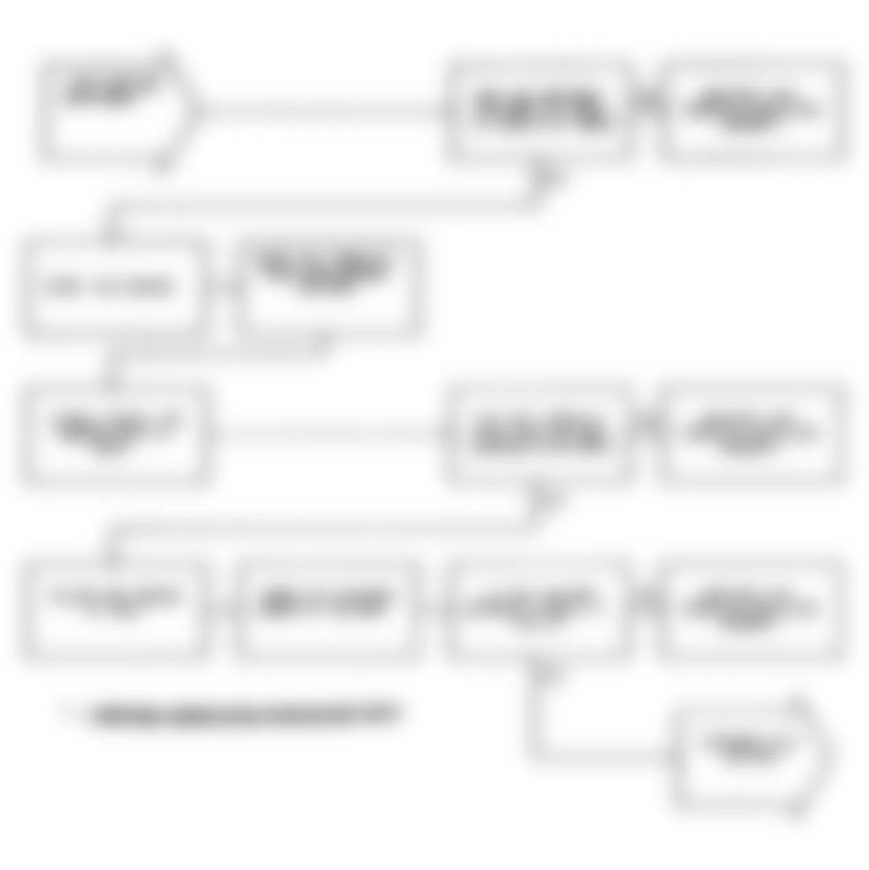
Jeep Cherokee Sport 1991 - NS-13A: PERFORMING NO FAULT CODE MECHANICAL TEST
At this point in the start and stall test procedure, you have determined that all of the engine control systems are operating properly. The engine control systems are NOT the cause of the start and stall problem.
The following items should be checked as possible causes:
- ENGINE VACUUM must be at least 13 in. Hg in Neutral.
- ENGINE VALVE TIMING must be within specification.
- ENGINE COMPRESSION must be within specification.
- EXHAUST SYSTEM must be free of restrictions.
- PCV SYSTEM must allow crankcase gases to flow freely.
- ENGINE CAMSHAFT & CRANKSHAFT SPROCKETS must be in good mechanical condition.
- TORQUE CONVERTER STALL SPEED must be within specifications.
- FUEL CONTAMINATION: Fuel should NOT have a high alcohol or water content.
- TECHNICAL SERVICE BULLETINS should be checked for possible solution to problem.
- SECONDARY IGNITION CHECK: Use an engine analyzer and check for abnormal scope pattern(s).
Any one or more of these items can give a start and stall related problem. They cannot be overlooked as possible causes.
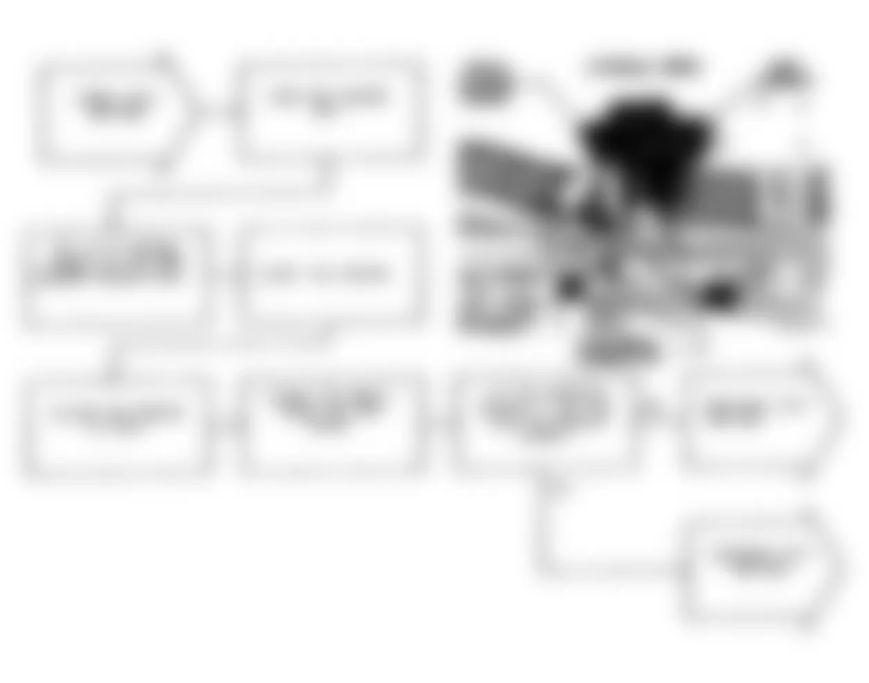
Jeep Cherokee Sport 1991 - DR-1A: CHECKING SYSTEM FOR FAULTS
NOTE: Battery must be fully charged and at rated capacity before performing any driveability test procedure. If vehicle starts and stalls repeatedly, perform NO START TEST NS-2A: CHECKING FUEL DELIVERY SYSTEM .
- Ensure ignition is off. Connect DRB-II to engine diagnostic connector. Connector is located on left side of engine compartment, near SBEC. See 1.
- Without starting engine, turn ignition on and access READ FAULTS function of DRB-II FUEL/IGN MENU. If DRB-II reads NO FAULTS, go to step 4). If DRB-II reads INTERNAL CONTROLLER FAILURE, replace engine controller and perform VERIFICATION PROCEDURE VER-2 .
- If DRB-II reads ENGINE IS COLD TOO LONG, service cooling system as required to bring system within specification and then perform VERIFICATION PROCEDURE VER-3 .
- Start engine and allow it to reach normal operating temperature. Manually run engine at 2000 RPM for at least 10 seconds and allow engine to return to idle.
- If vehicle is equipped with air conditioning, place A/C-heater blower fan on low speed and turn A/C system on. If vehicle stalls when A/C system is turned on, go to next step. If vehicle does not stall, go to step 8).
- Turn ignition off. Disconnect 60-pin engine controller connector. Inspect connector for proper wire placement, corrosion, damaged terminals, or pushed-out pins. Repair as necessary and go to next step.
- Turn ignition on. Place DRB-II in voltmeter mode. Probe engine controller connector Dark Blue wire (pin No. 9). If reading is less than 10 volts, repair open in Dark Blue wire. If reading is more than 10 volts, replace engine controller and perform VERIFICATION PROCEDURE VER-2 .
- If vehicle is equipped with an automatic transmission, step on brake pedal and shift through all gears. Return shift lever to PARK position. Use DRB-II to read fault messages and go to next step.
- If DRB-II once again reads NO FAULTS, check for technical service bulletins that relate to this driveability problem. If no related technical service bulletins are found, perform DRIVEABILITY TEST DR-26A: CHECKING SECONDARY IGNITION & TIMING .
- If pertinent technical service bulletins are found, perform the corrective action given. If driveability problems continue after performing corrective action, perform DRIVEABILITY TEST DR-26A: CHECKING SECONDARY IGNITION & TIMING .
Jeep Cherokee Sport 1991 DRB-II FAULT MESSAGES
DRB-II Message (1) Hard Fault (2) Intermittent Fault A/C Clutch Relay Circuit DR-22A DR-35A Automatic Idle Speed Motor Circuits DR-15A DR-37A Charge Temperature Sensor Voltage High DR-11A DR-36A Charge Temperature Sensor Voltage Low DR-12A DR-36A Controller Failure EEPROM Write Denied DR-25A DR-25A Controller Failure EMR Miles Not Stored DR-25A DR-25A Coolant Sensor Voltage Too High DR-9A DR-36A Coolant Sensor Voltage Too Low DR-10A DR-36A Injector No. 1 Control Circuit DR-16A DR-38A Injector No. 2 Control Circuit DR-17A DR-38A Injector No. 3 Control Circuit DR-18A DR-38A Injector No. 4 Control Circuit DR-19A DR-38A Injector No. 5 Control Circuit DR-20A DR-38A Injector No. 6 Control Circuit DR-21A DR-38A MAP Voltage Too High DR-5A DR-36A MAP Voltage Too Low DR-4A DR-36A No ASD Relay Voltage Sense At Controller DR-24A DR-24A No Change In MAP From Start To Run DR-3A DR-36B No Vehicle Speed Signal DR-6A DR-6A O2 Signal Shorted To Voltage DR-8A DR-8A O2 Signal Stays At Center DR-7A DR-7A O2 Signal Stays Below Center (Lean) DR-26A DR-26A O2 Signal Stays Above Center (Rich) DR-26A DR-26A Radiator Fan Relay Circuit DR-23A DR-35A Slow Change In Idle MAP Signal DR-2A DR-36A Throttle Position Sensor Voltage High DR-13A DR-36A Throttle Position Sensor Voltage Low DR-14A DR-36A
(1) Key counter is "0".
(2) Key counter is greater than "0".
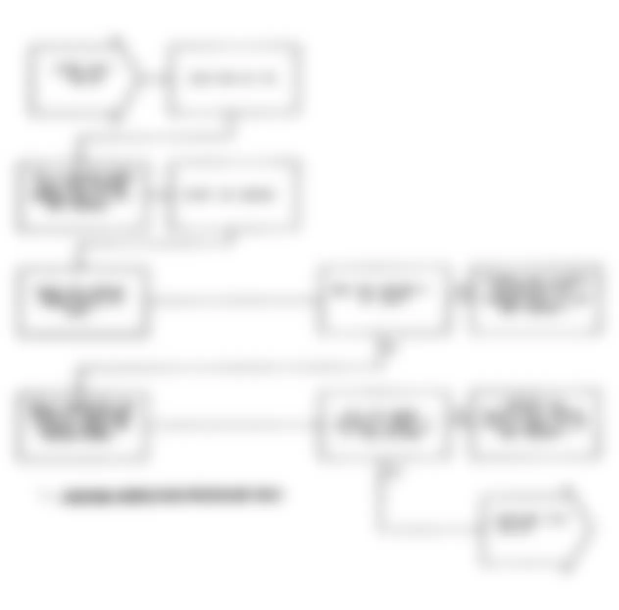
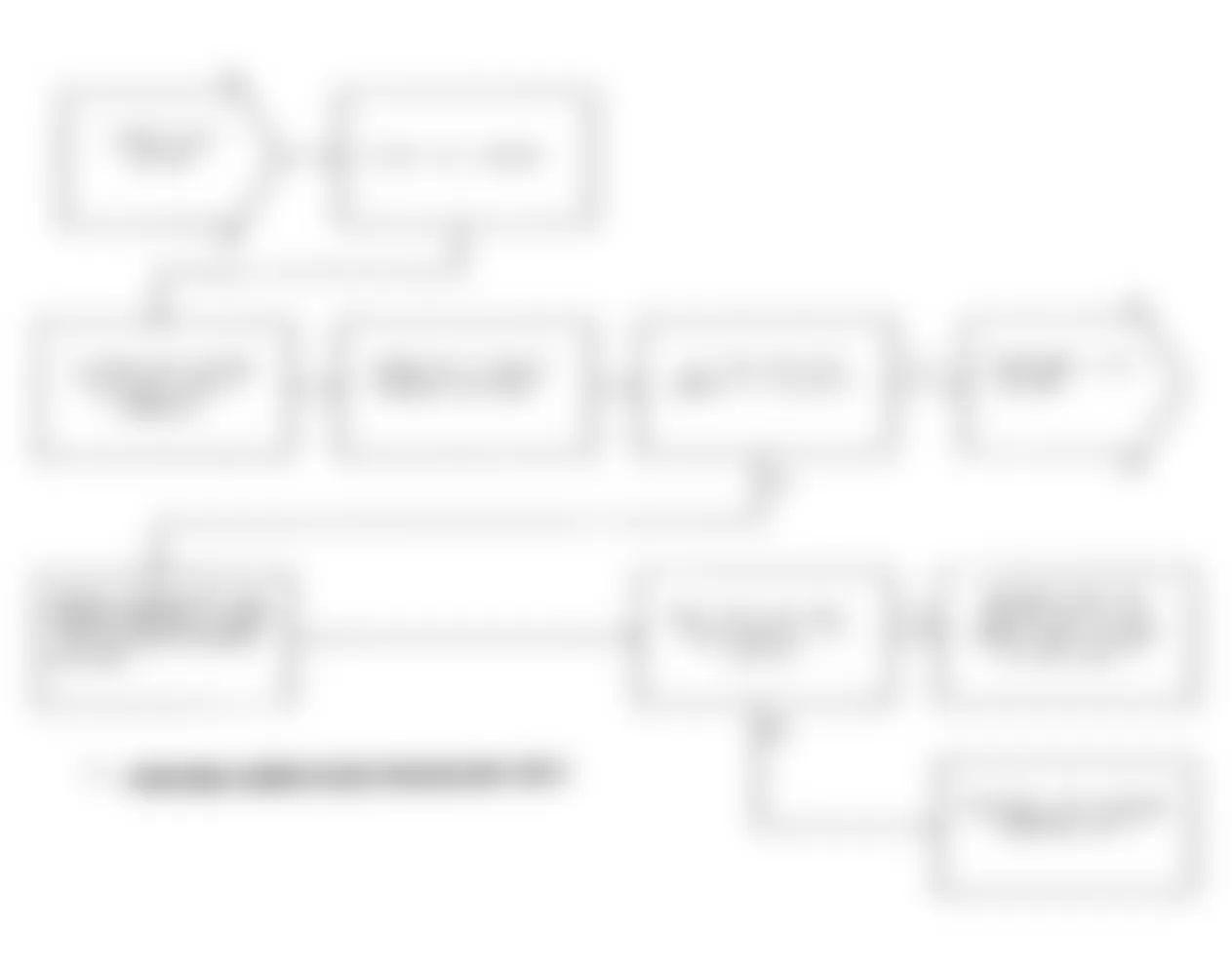
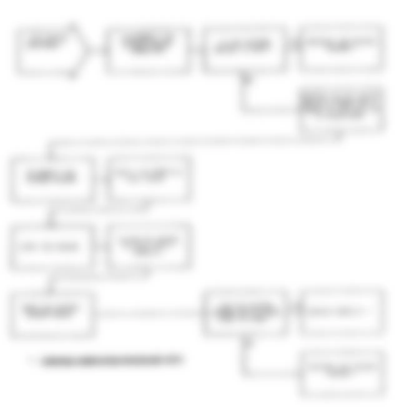
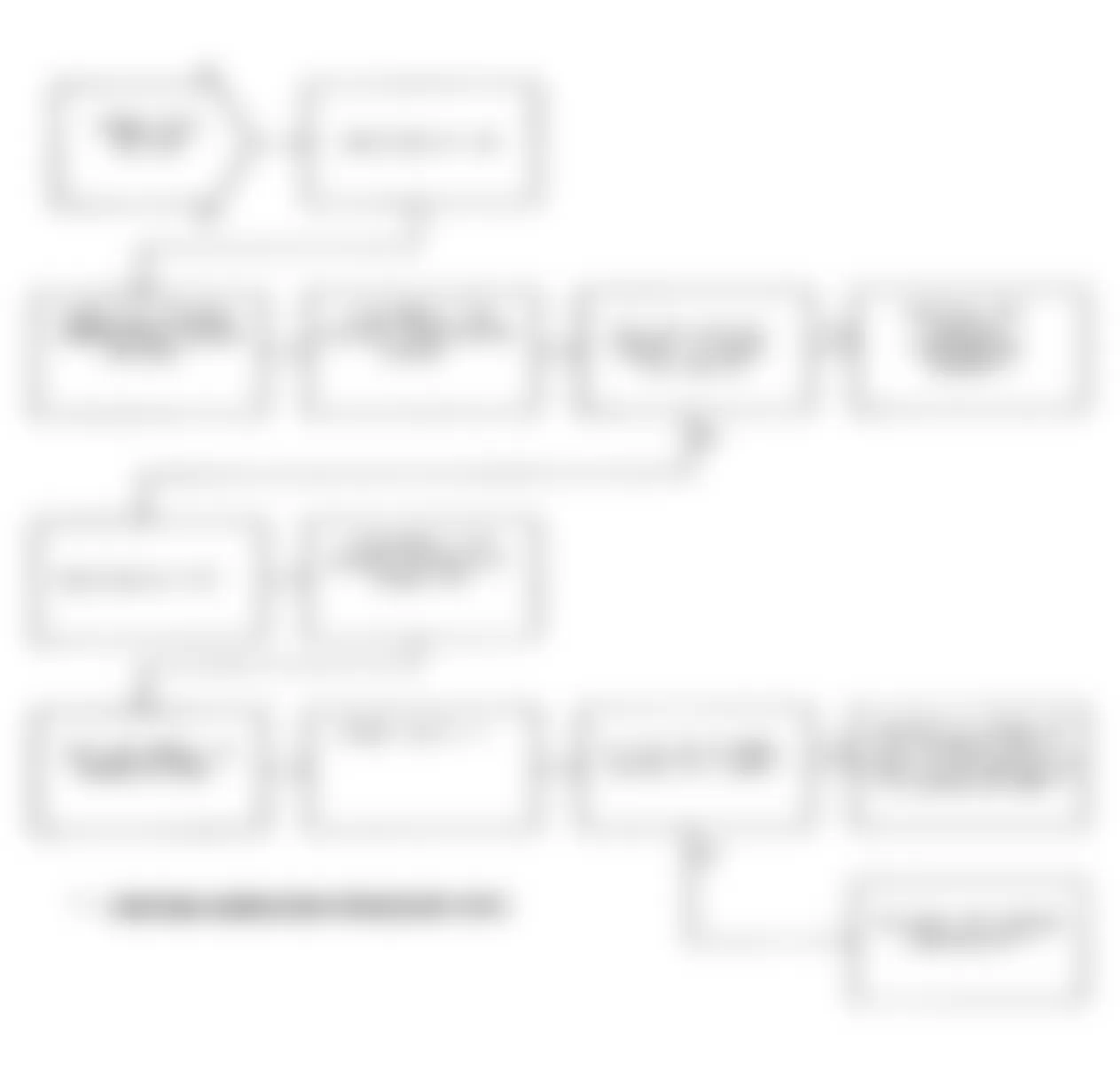
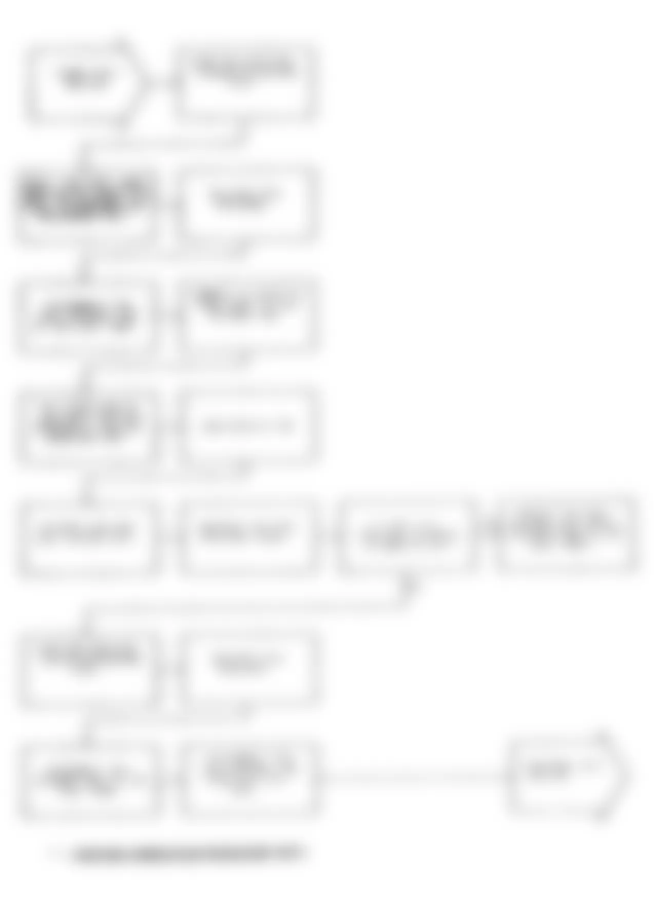
Jeep Cherokee Sport 1991 - DR-2A: REPAIRING SLOW CHANGE IN IDLE MAP SIGNAL

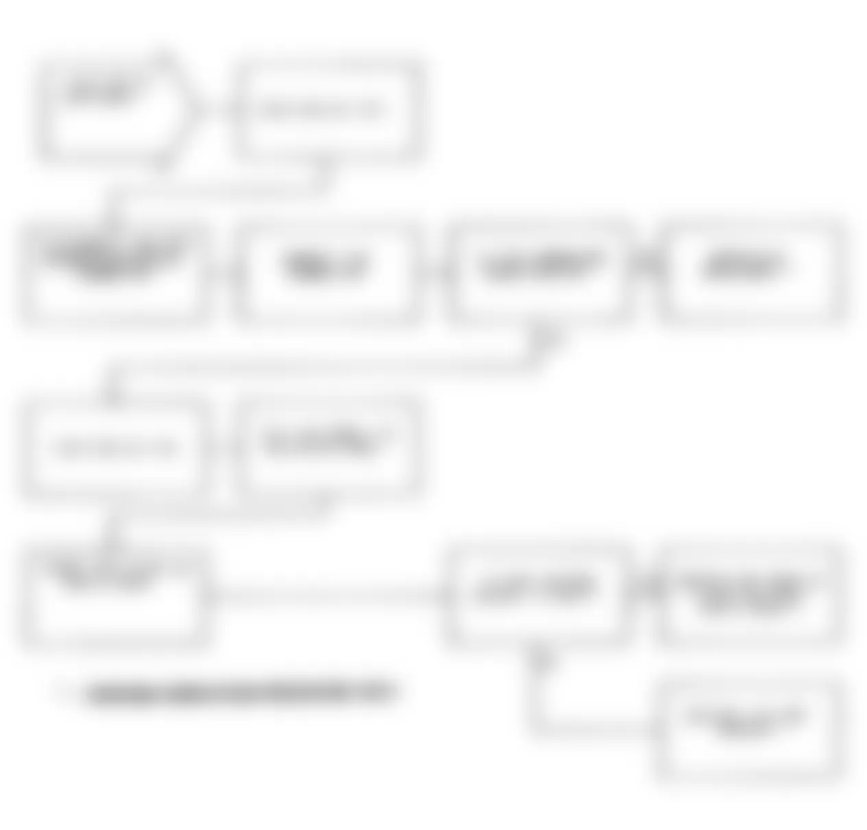
Jeep Cherokee Sport 1991 - DR-3A: REPAIRING NO CHANGE IN MAP FROM START TO RUN
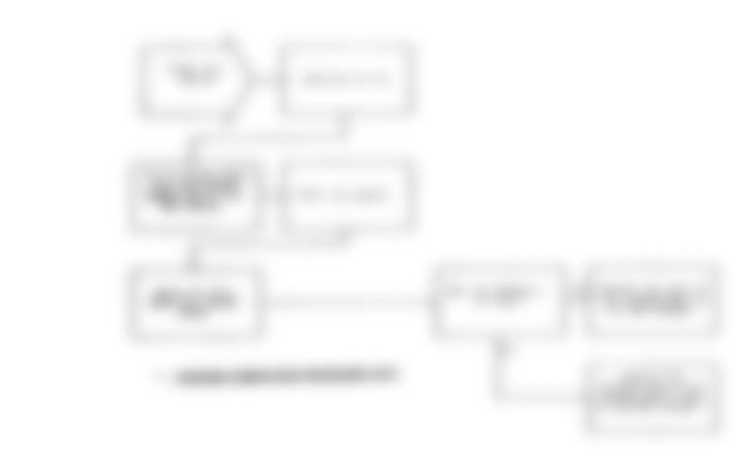
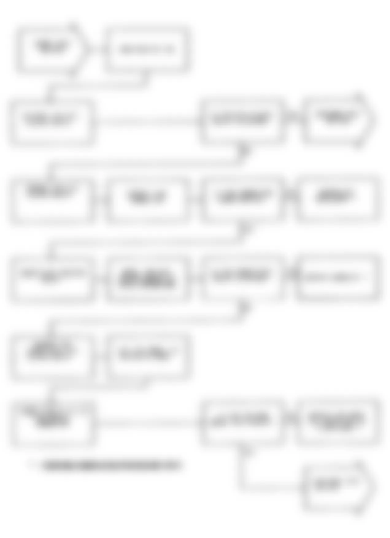
Jeep Cherokee Sport 1991 - DR-4A: REPAIRING MAP VOLTAGE TOO LOW

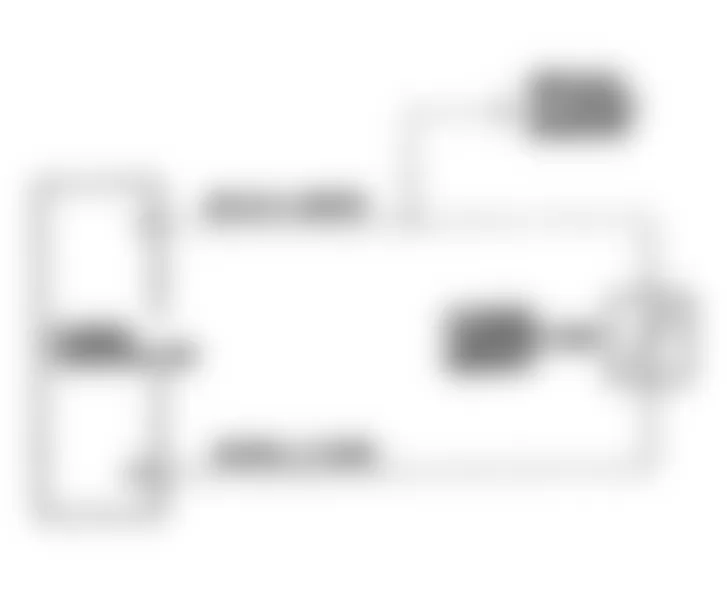
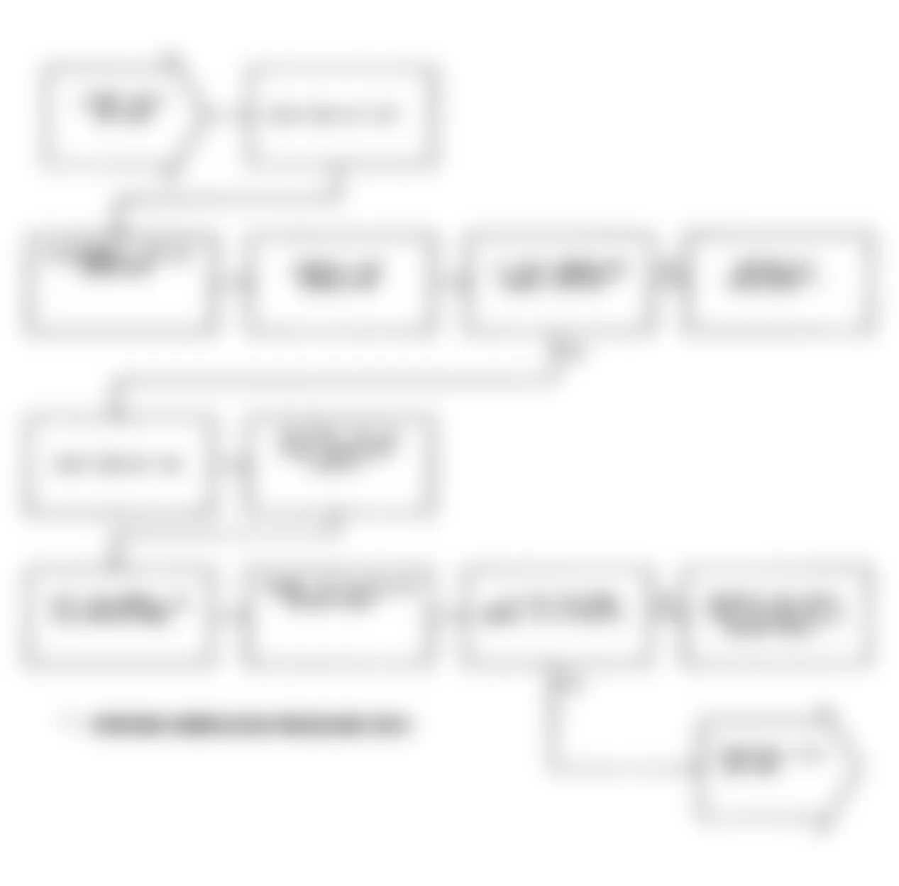
Fig. 81: Jeep Cherokee Sport 1991 - Component Locations - Test DR-4A Map Voltage Too Low Fault
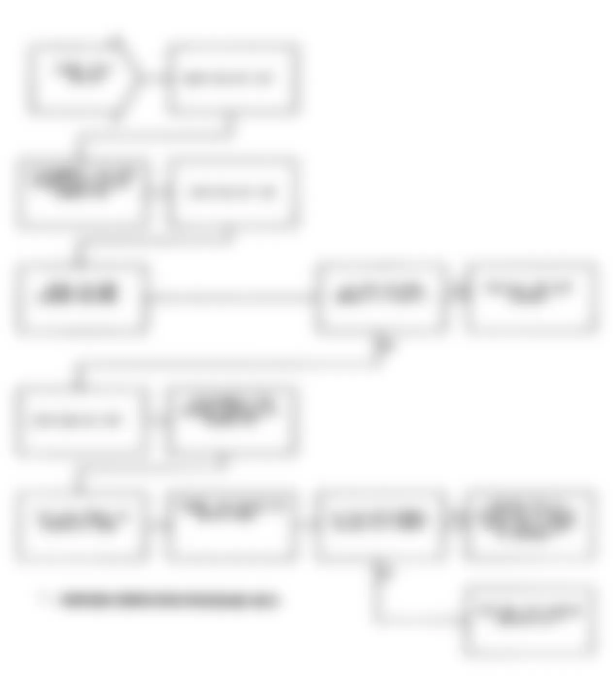
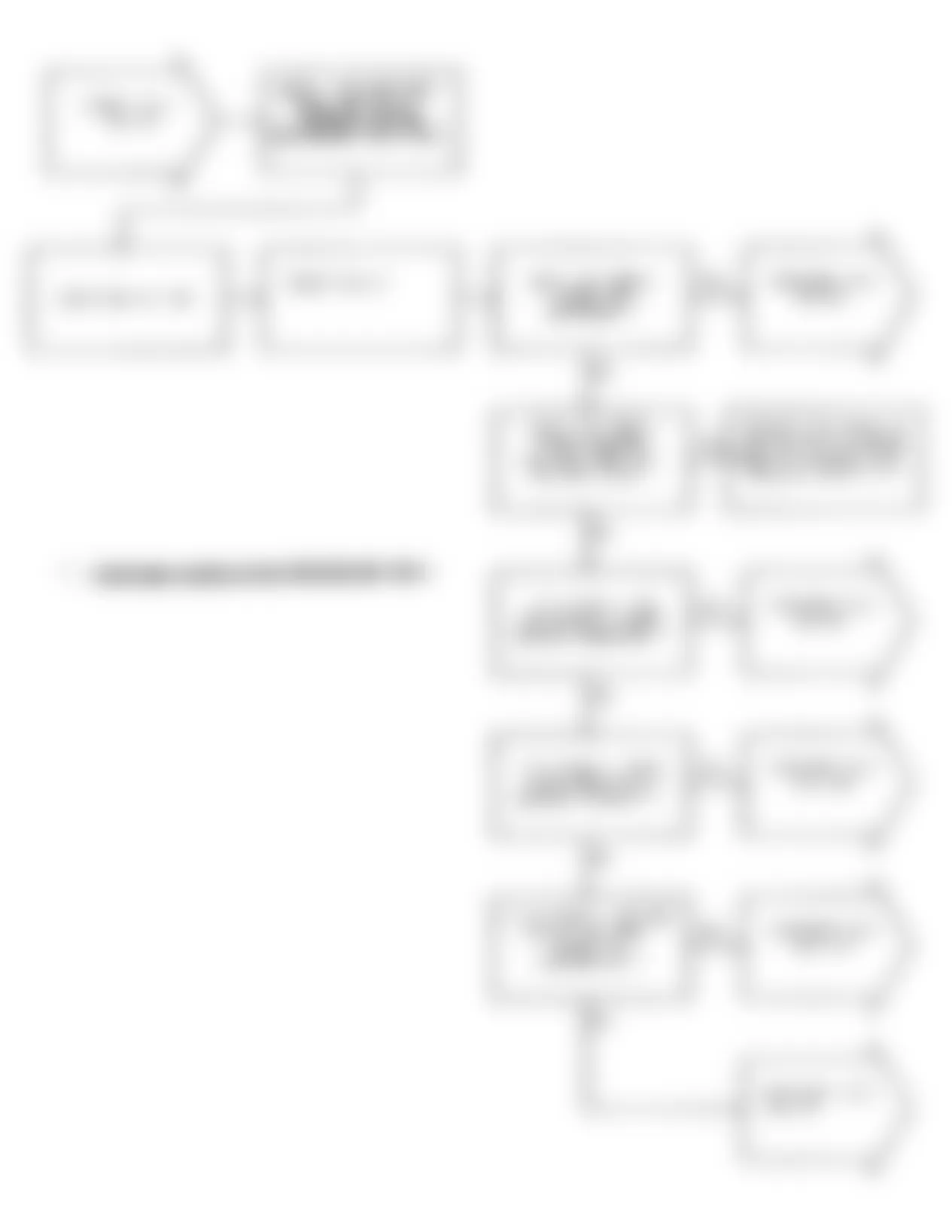
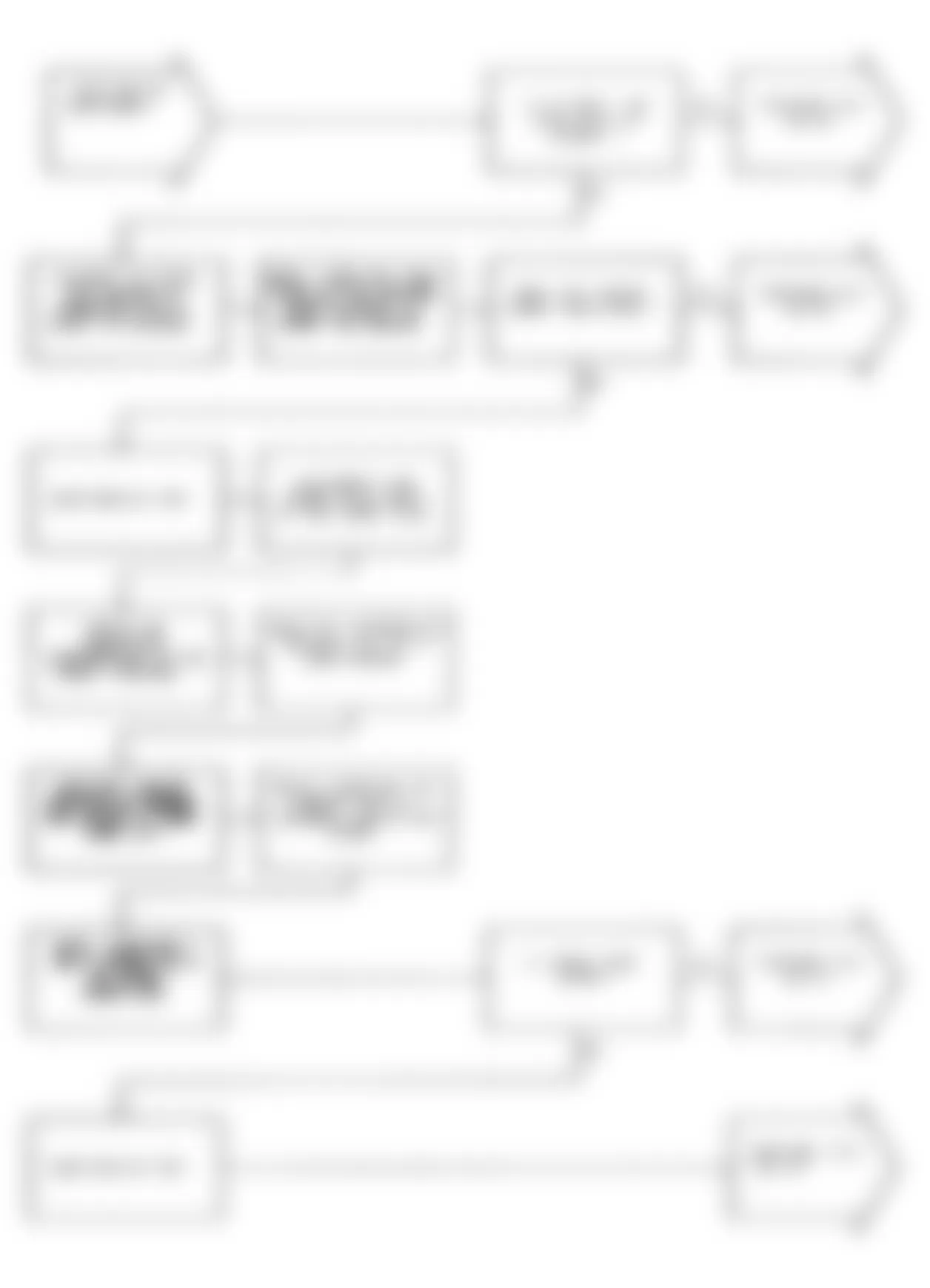
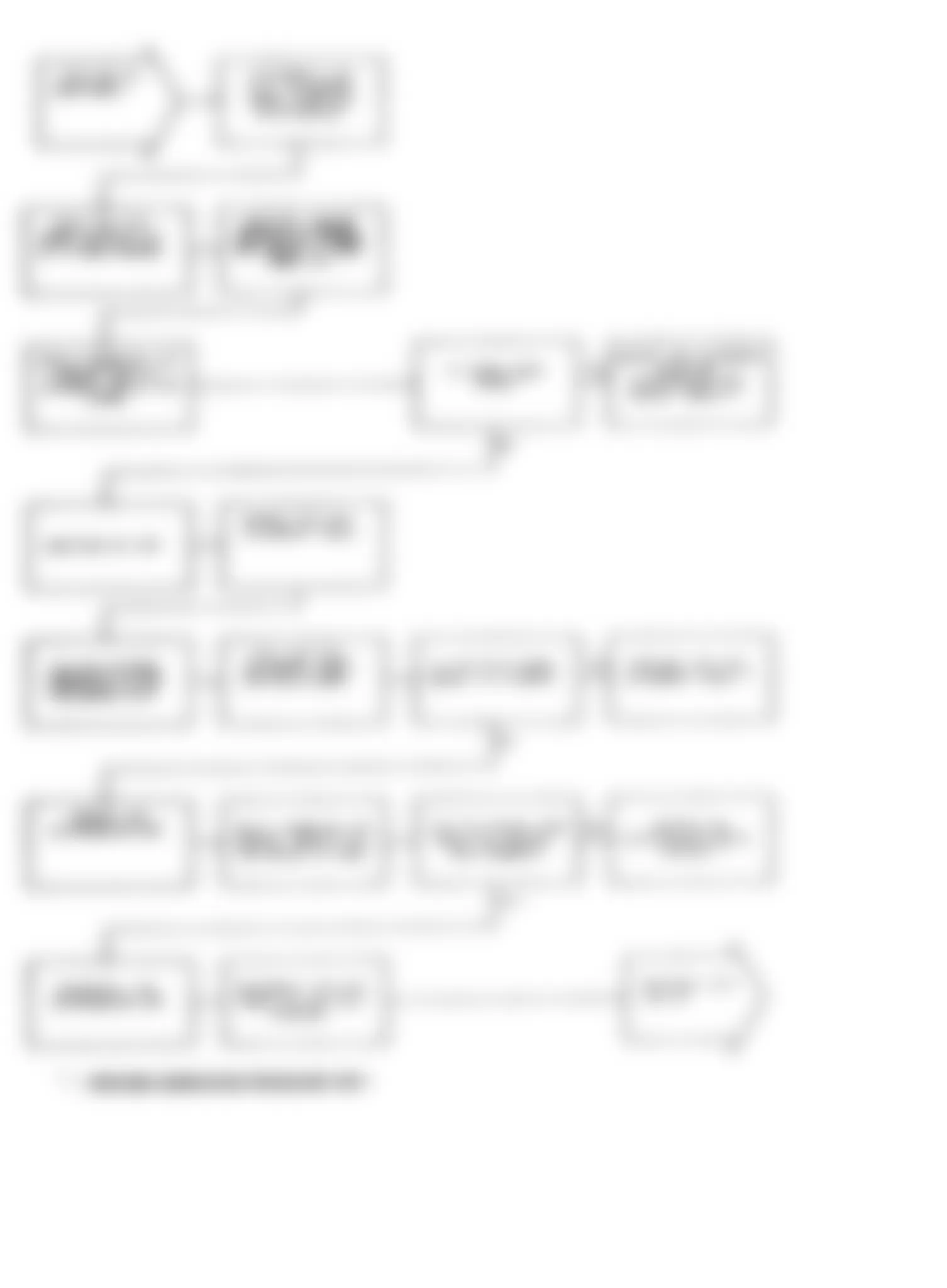
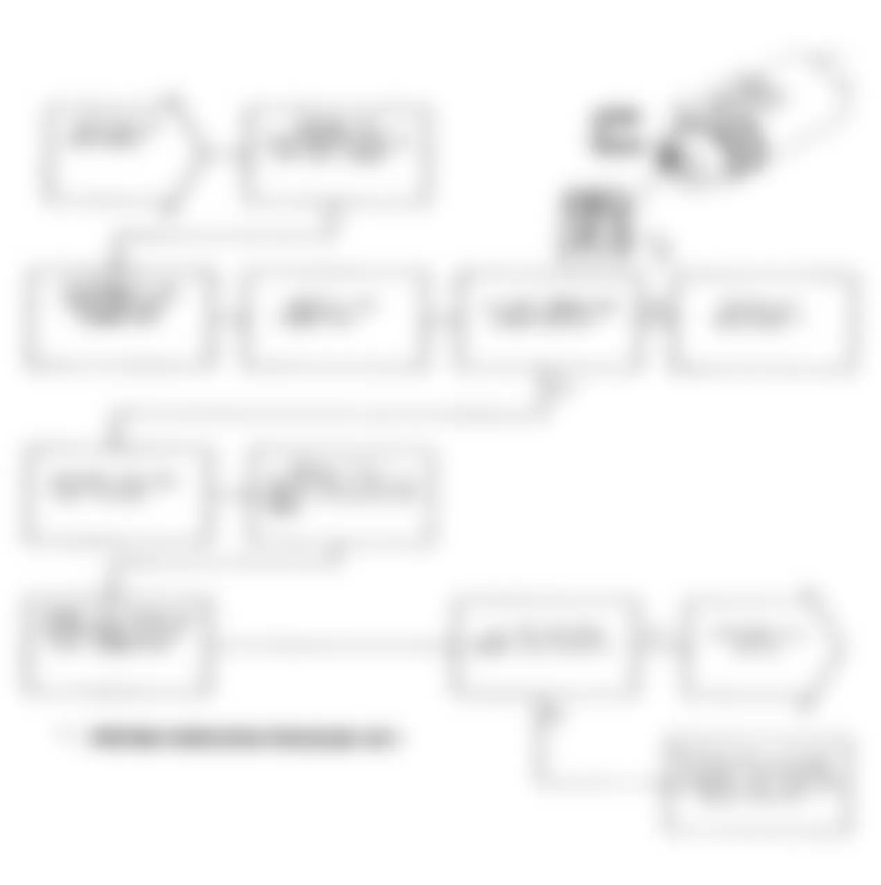
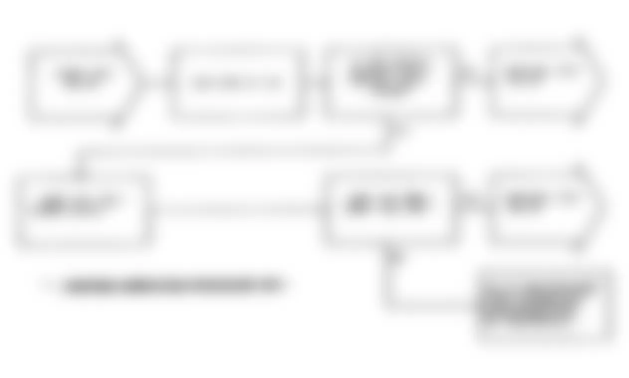
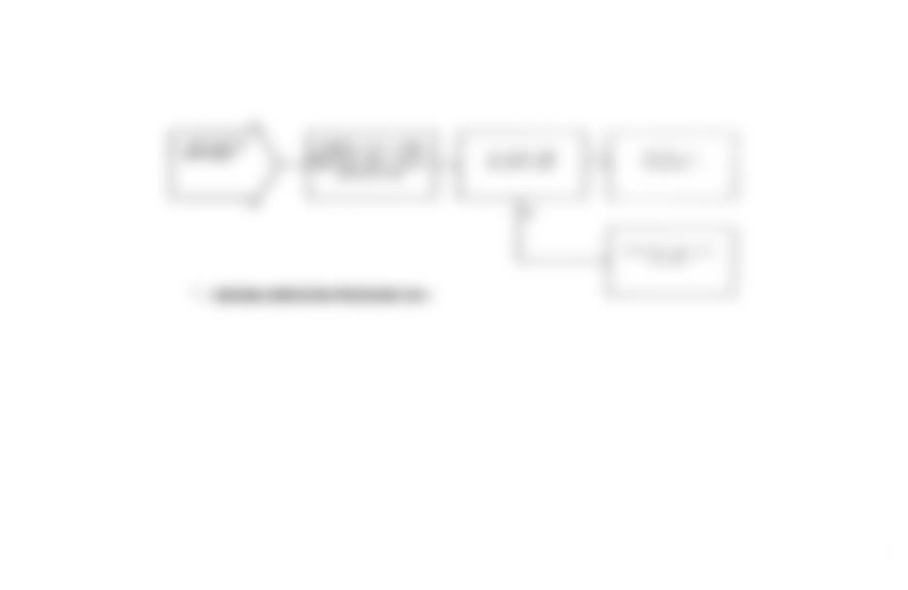
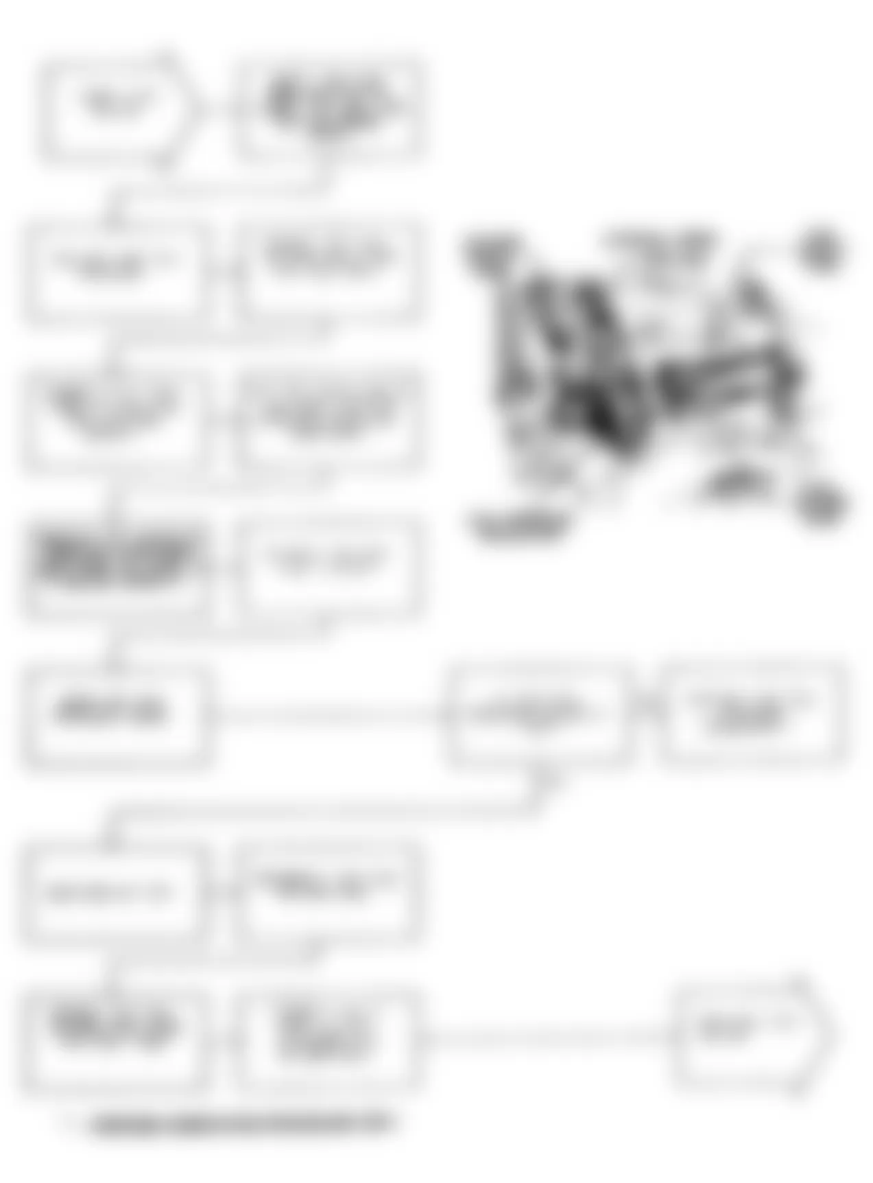
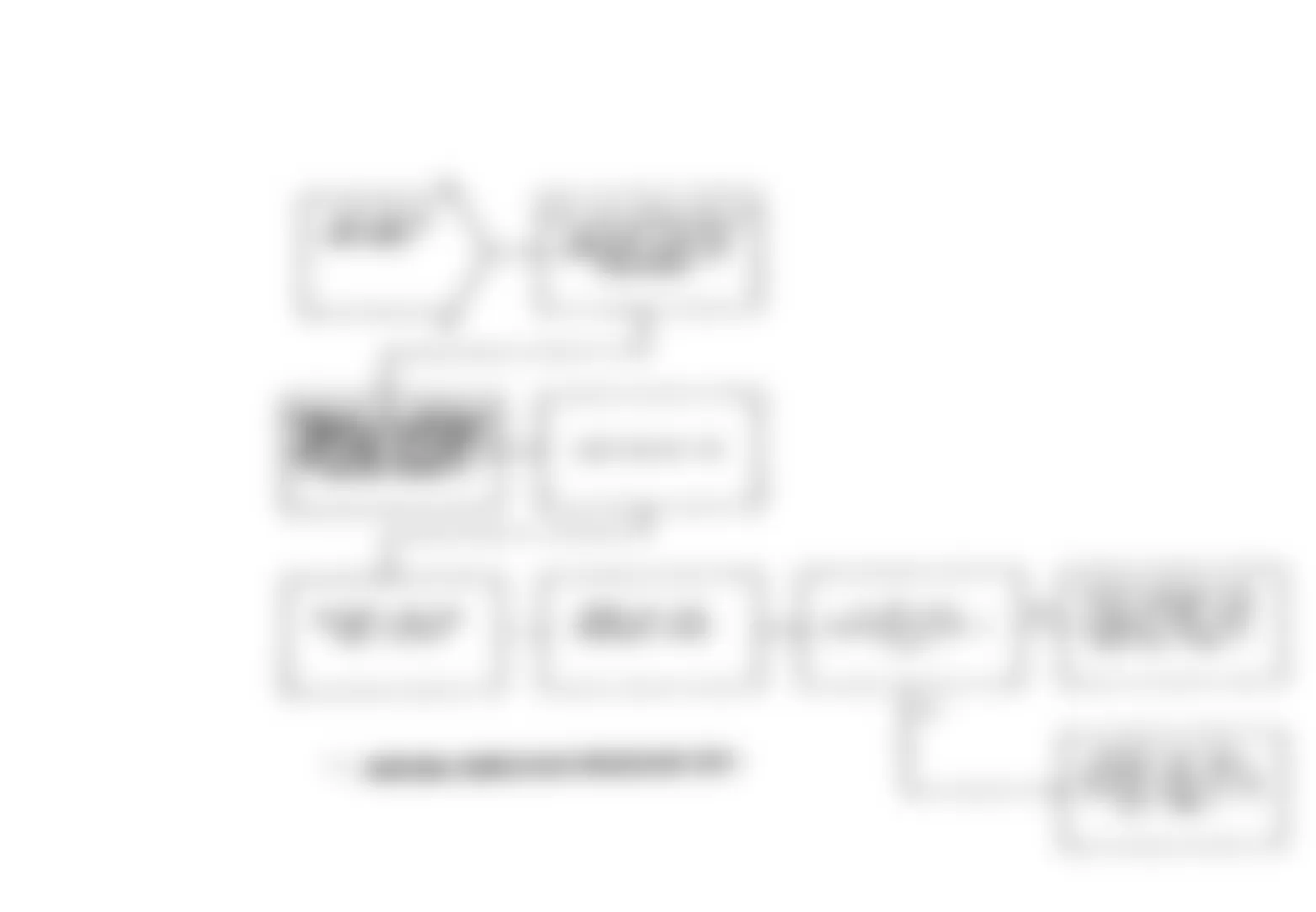
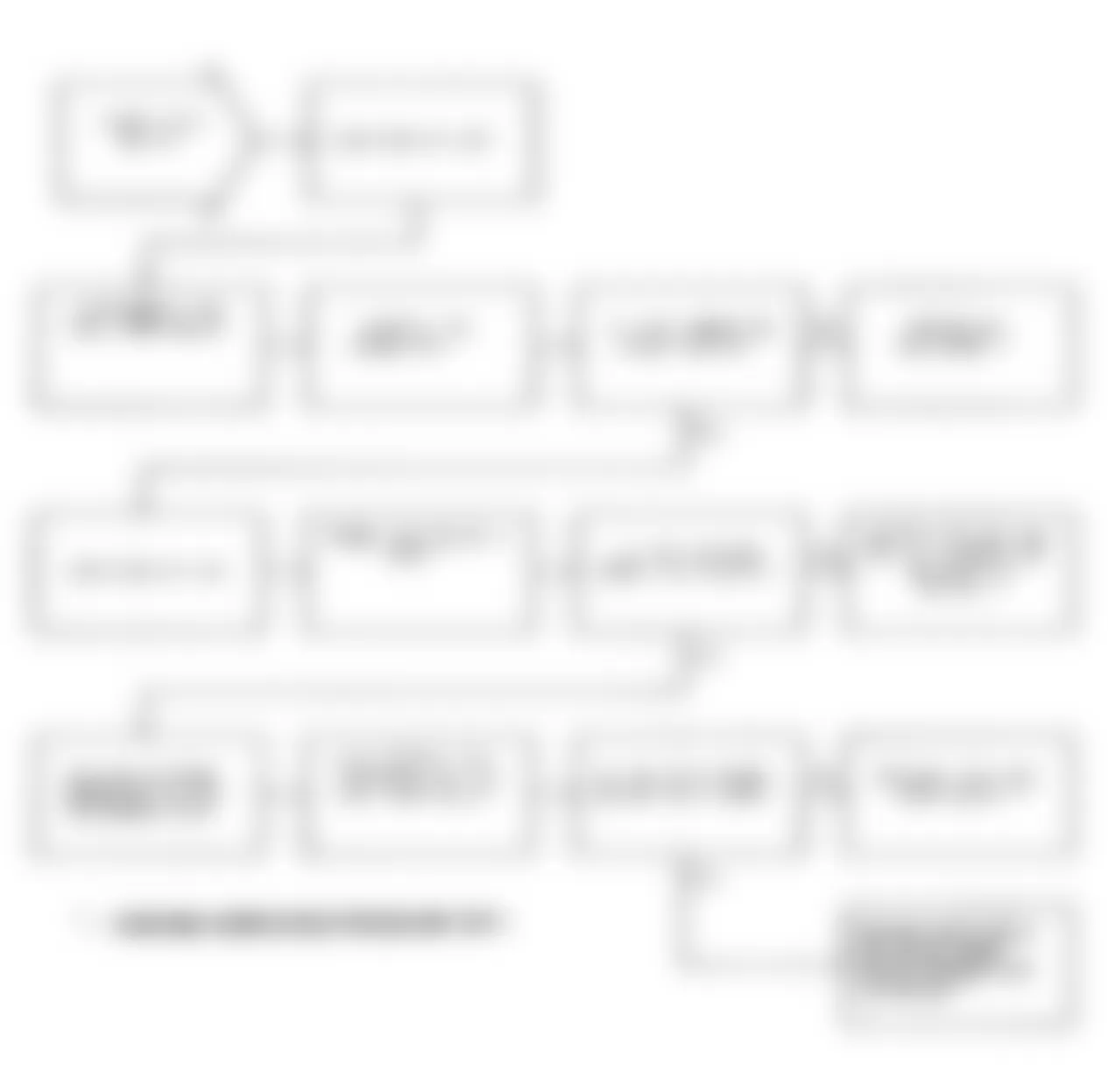
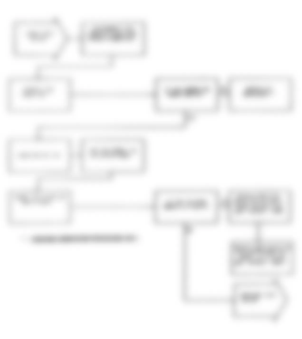
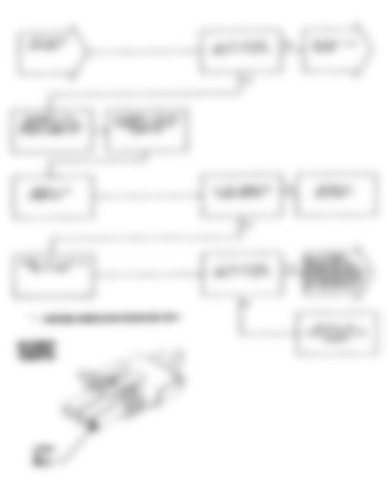
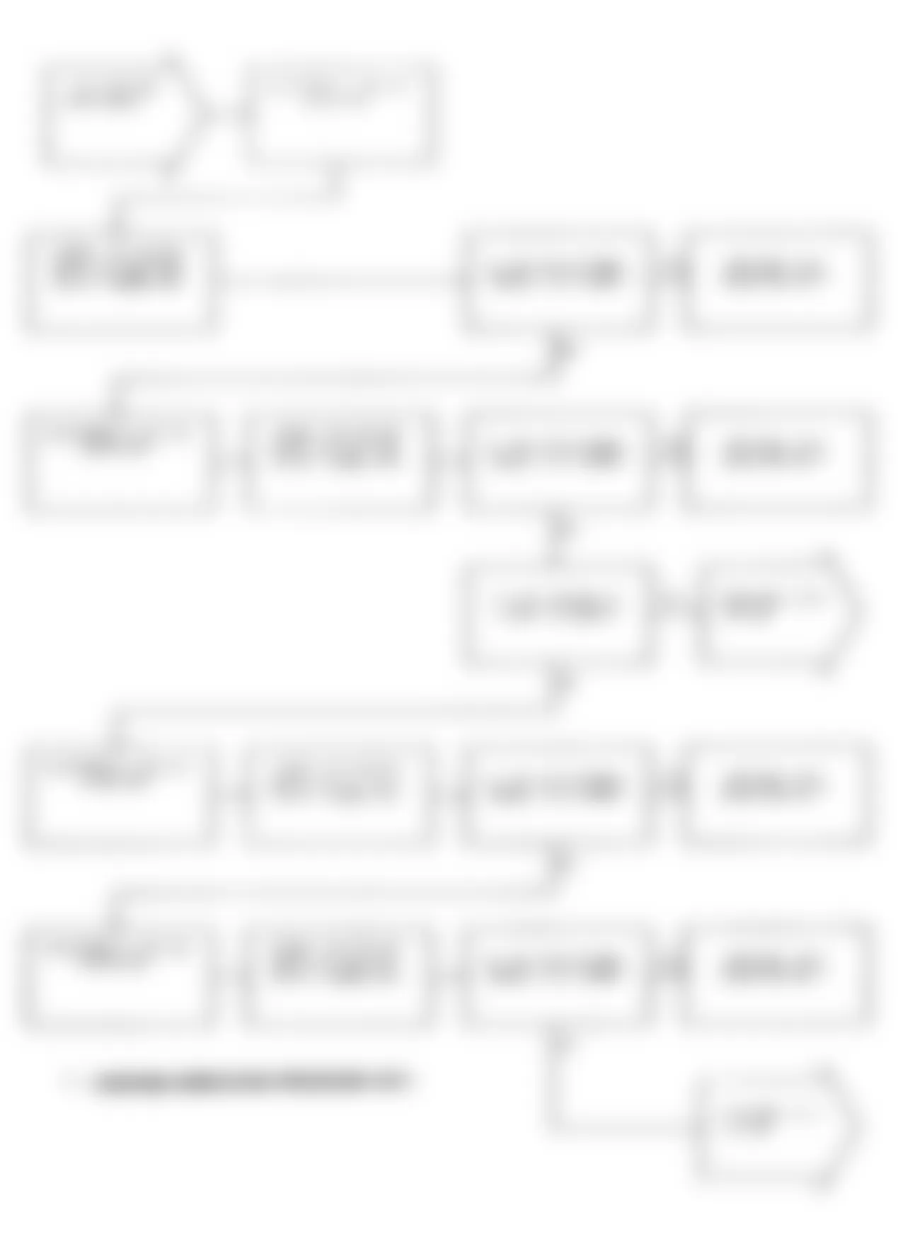
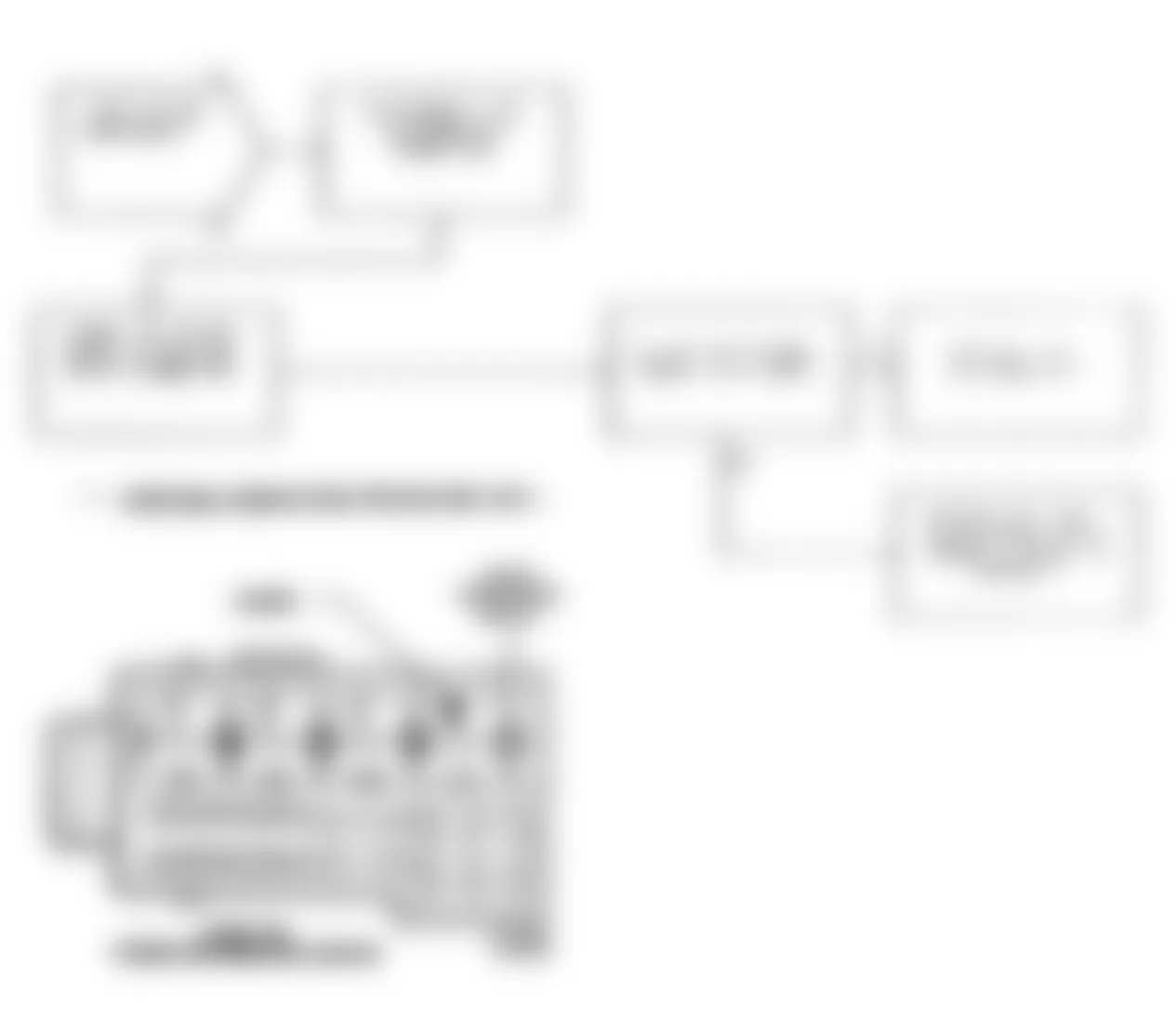
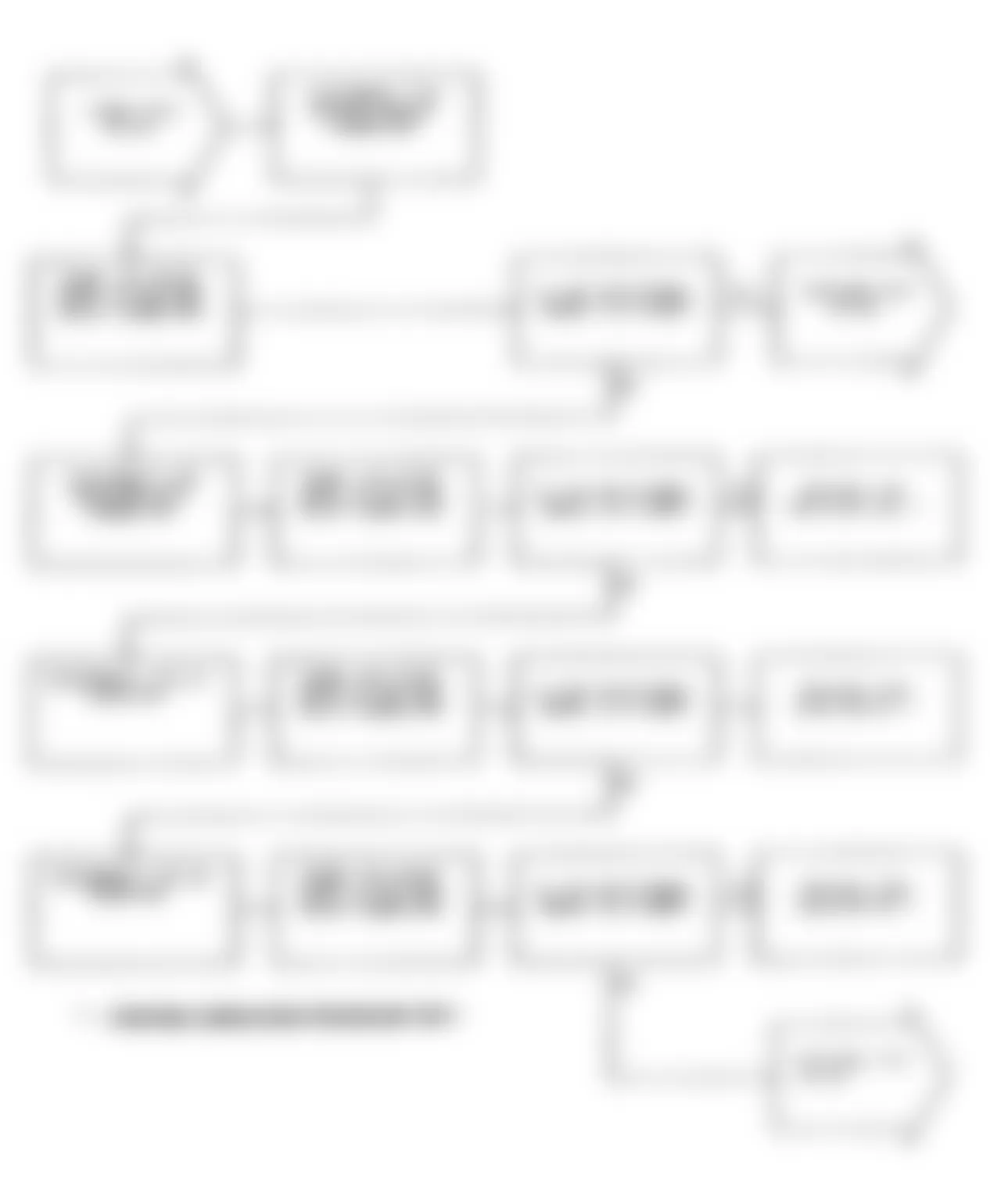
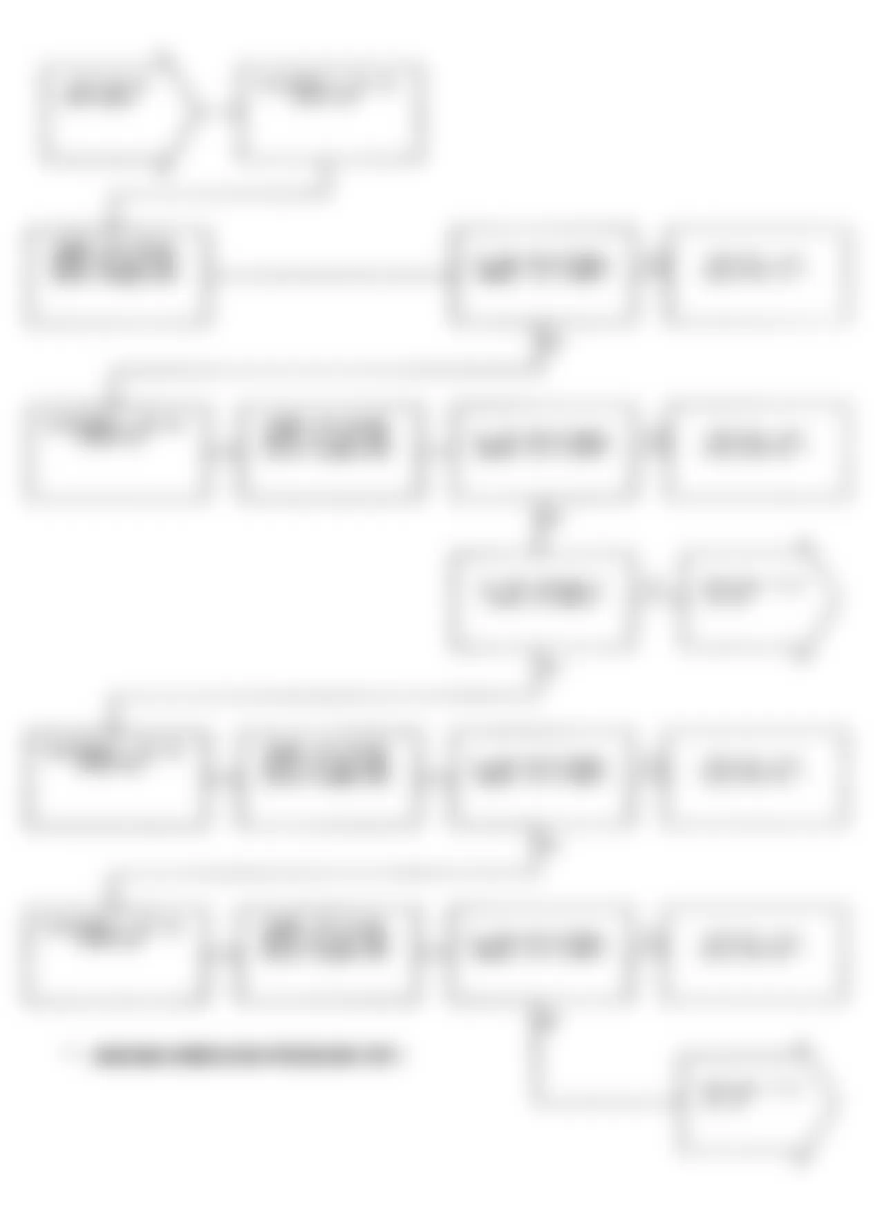
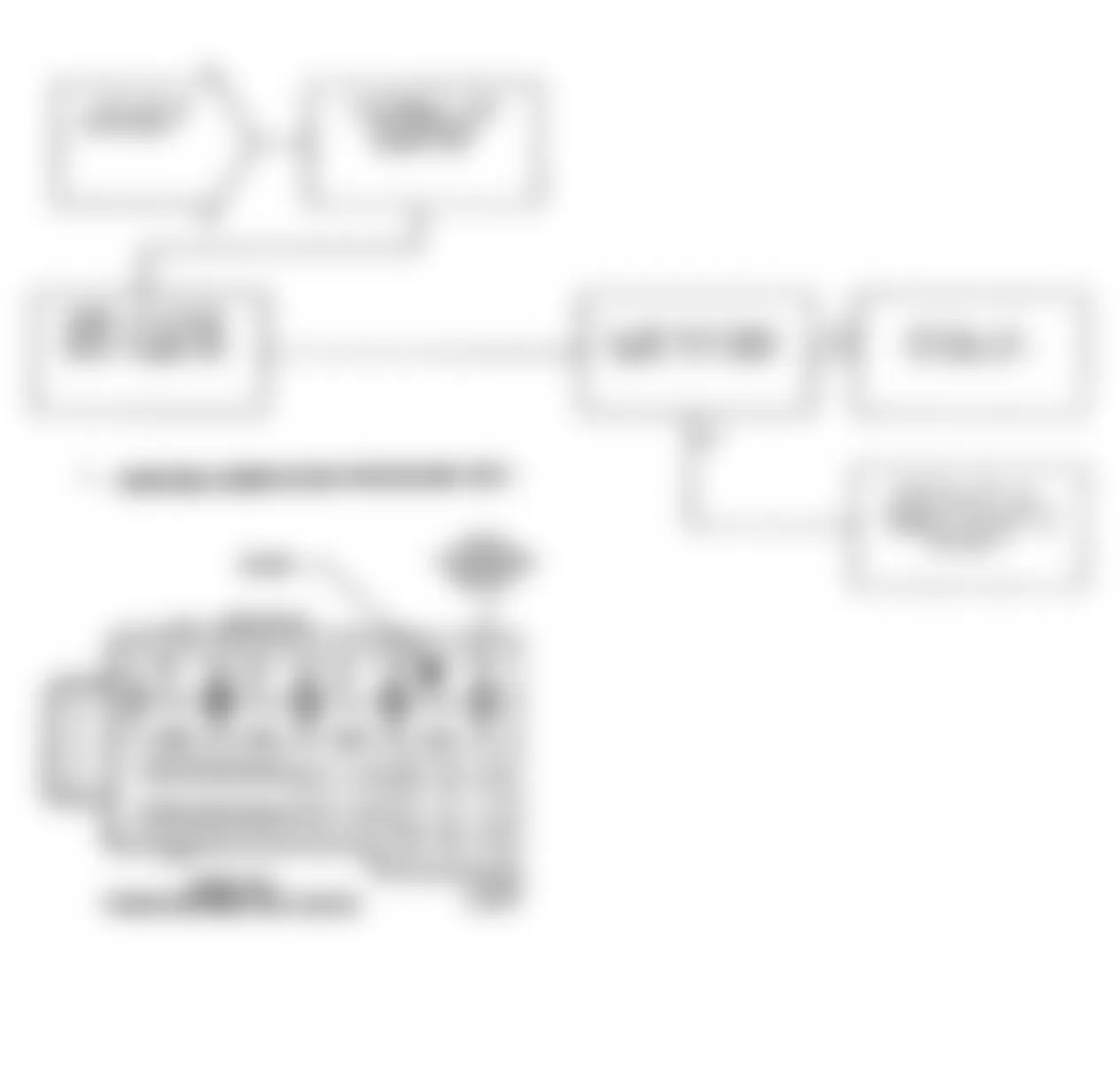
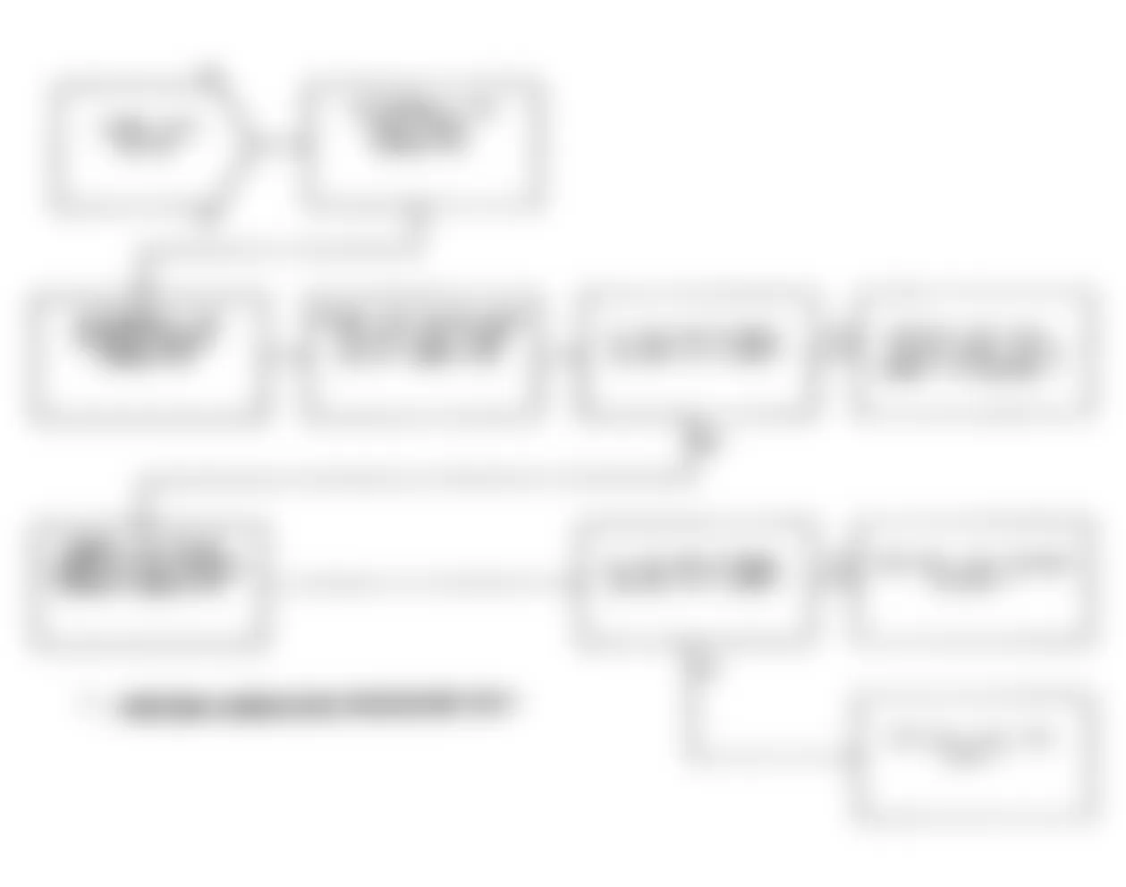
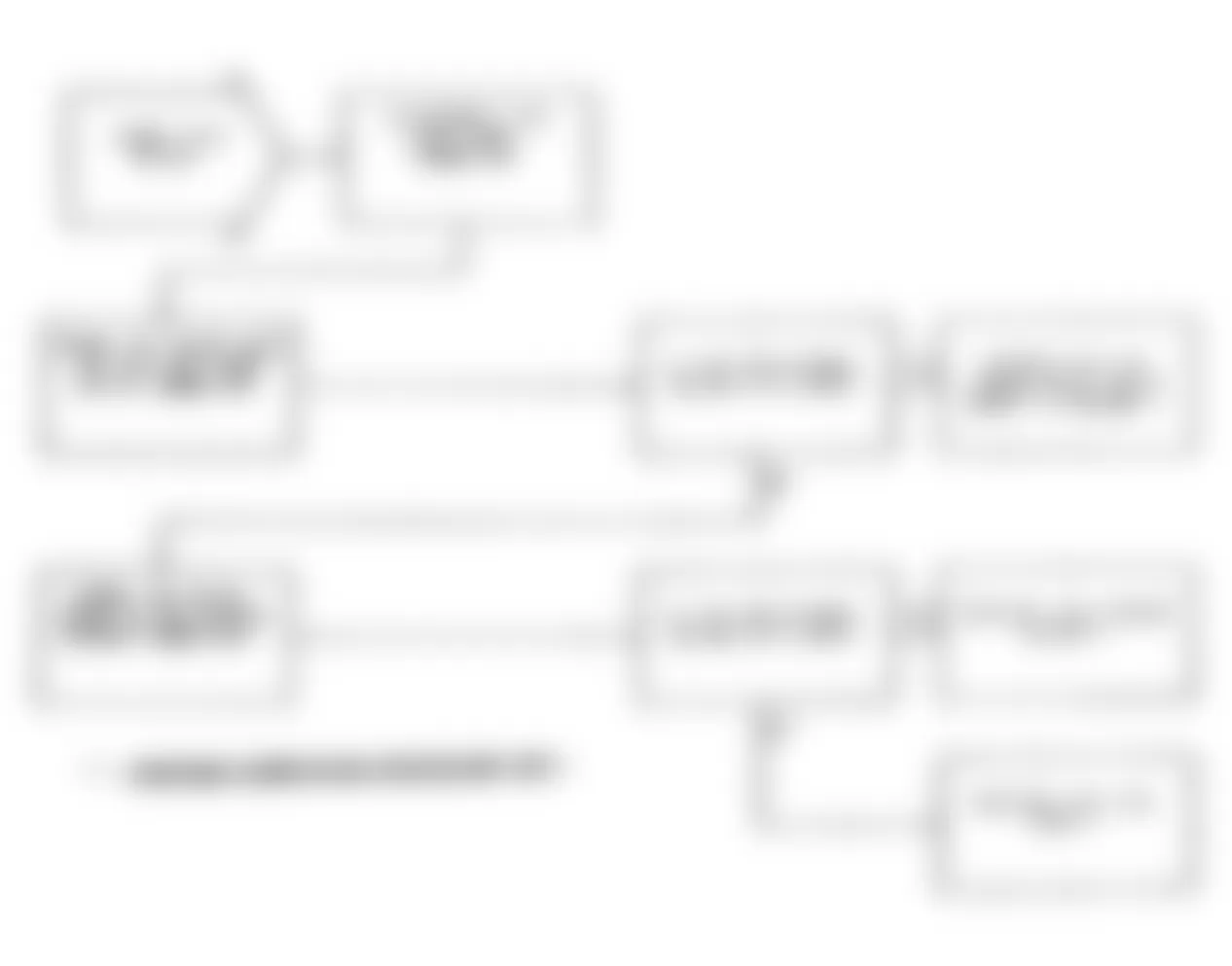
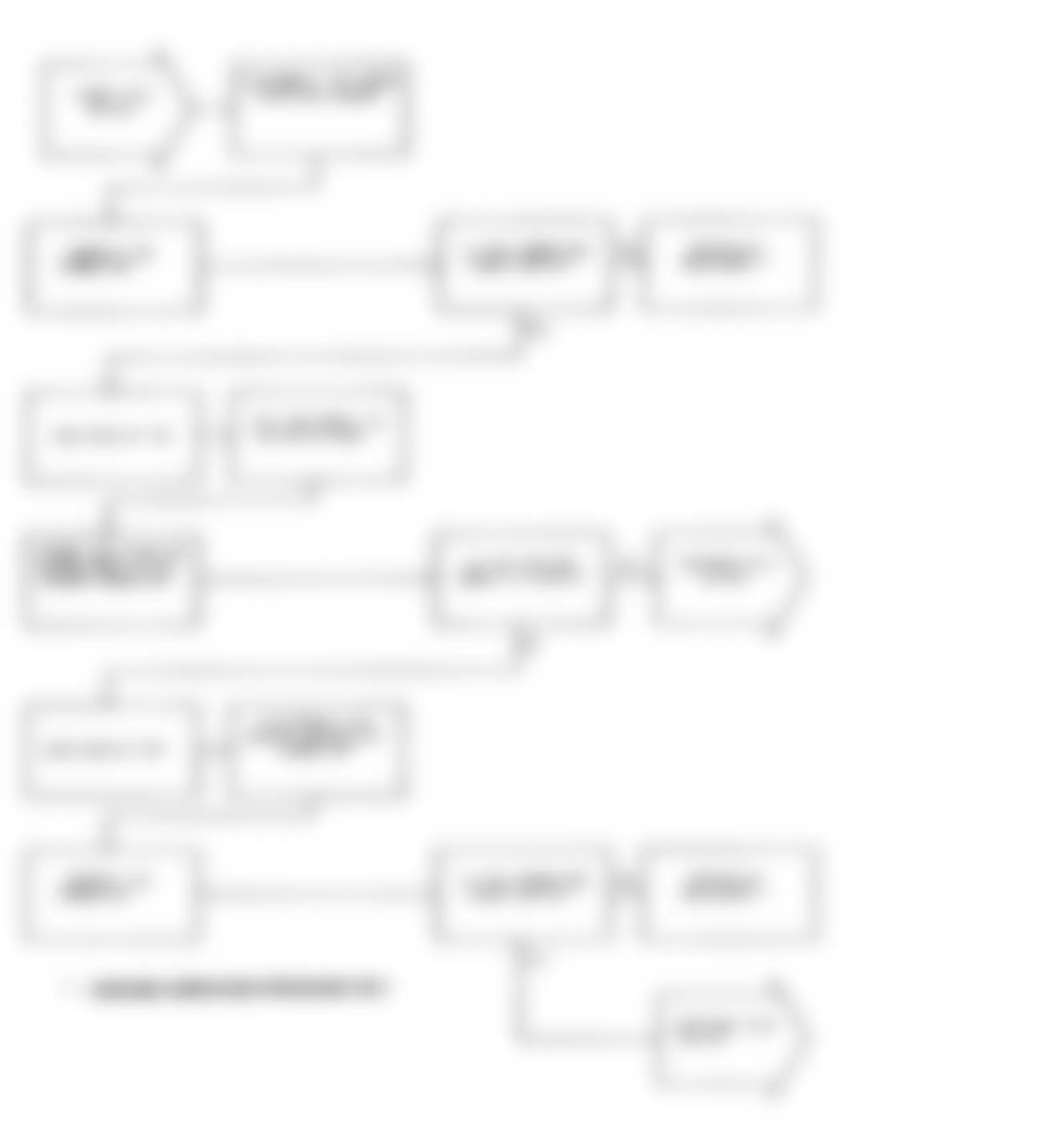
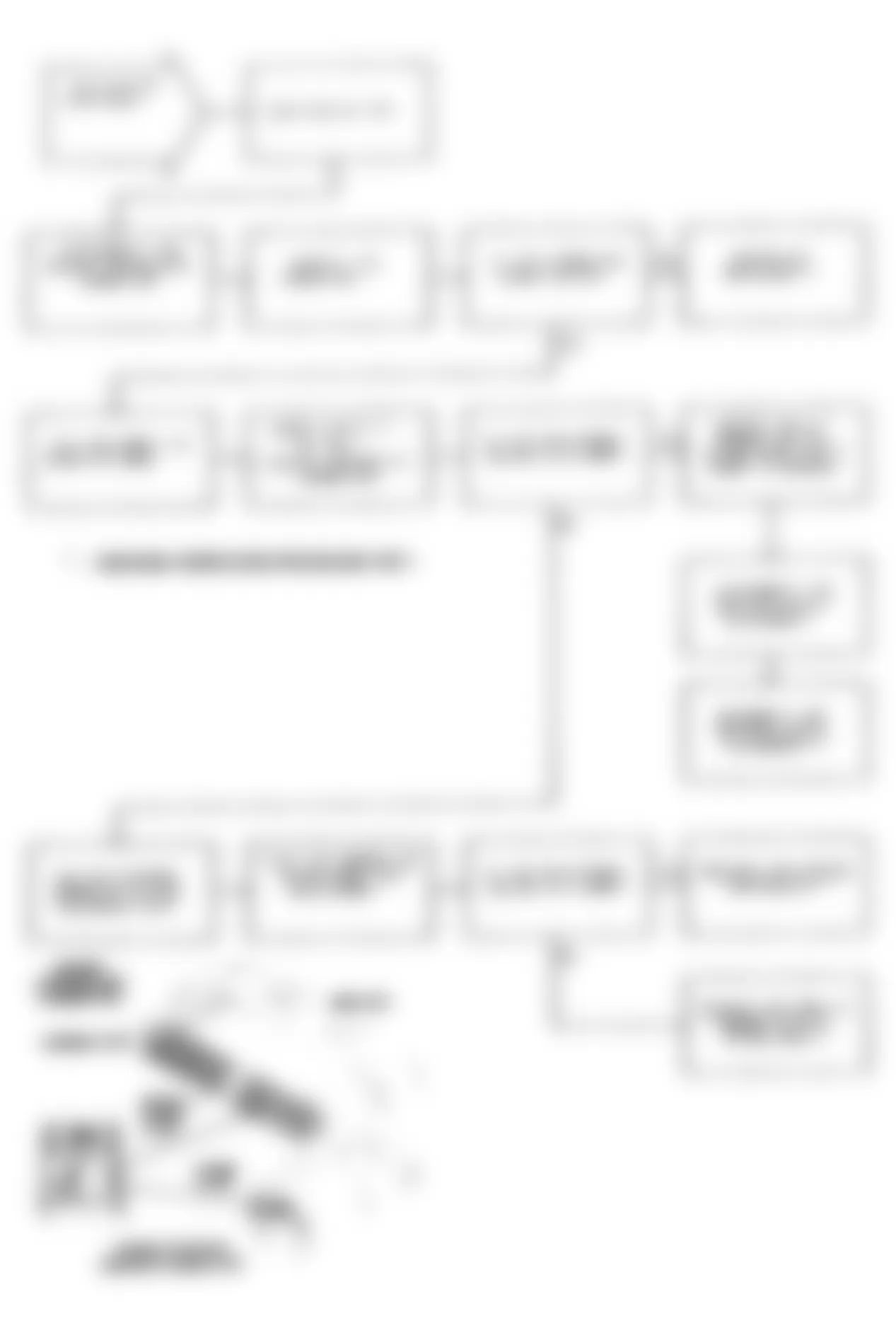
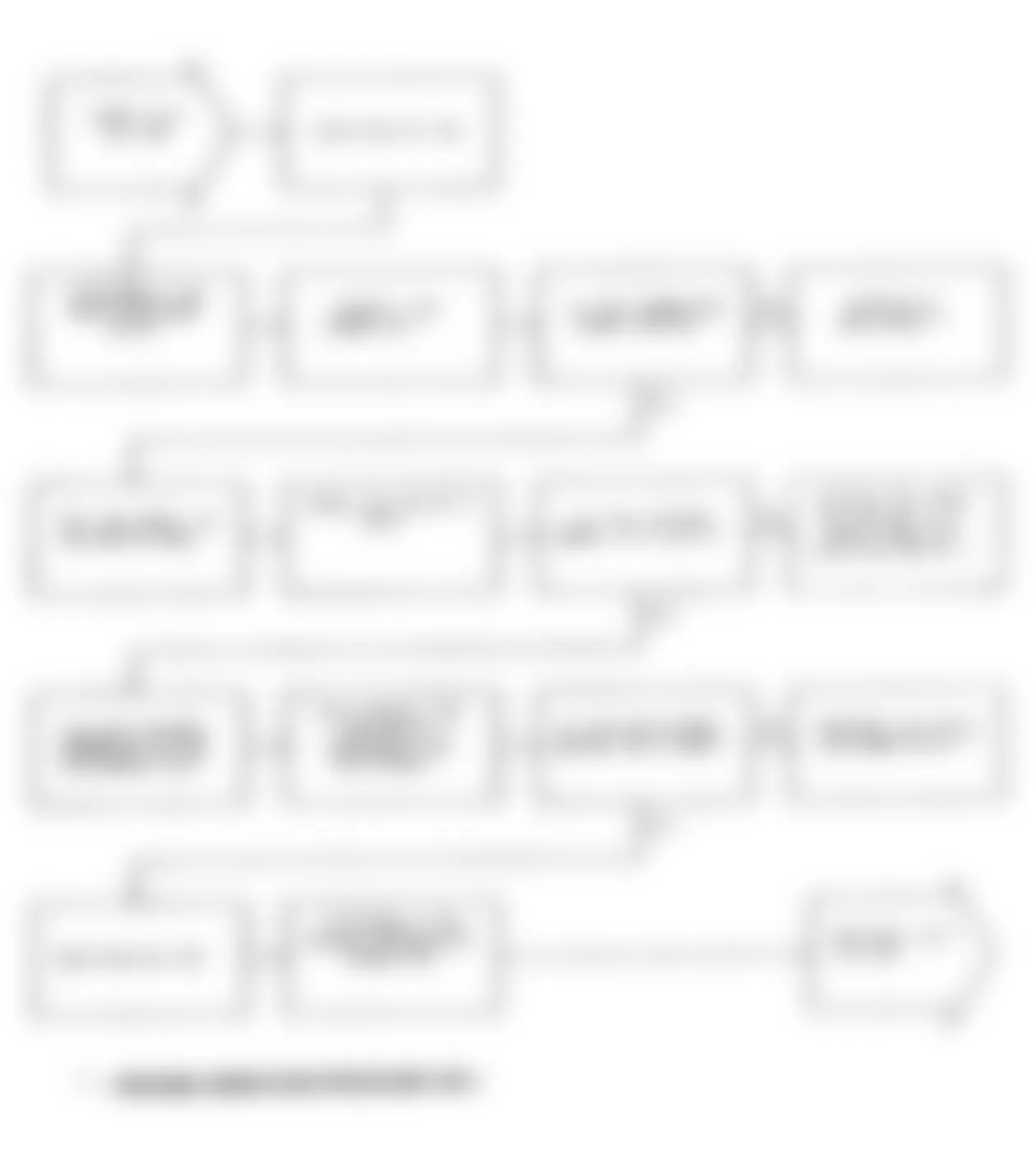
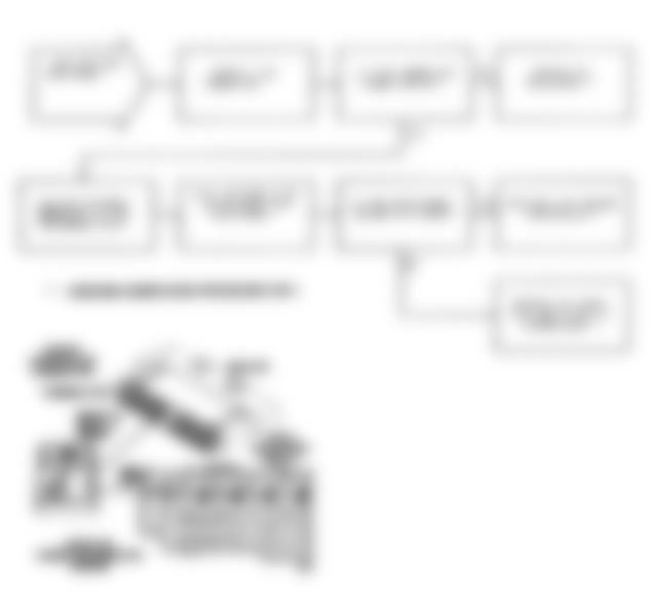
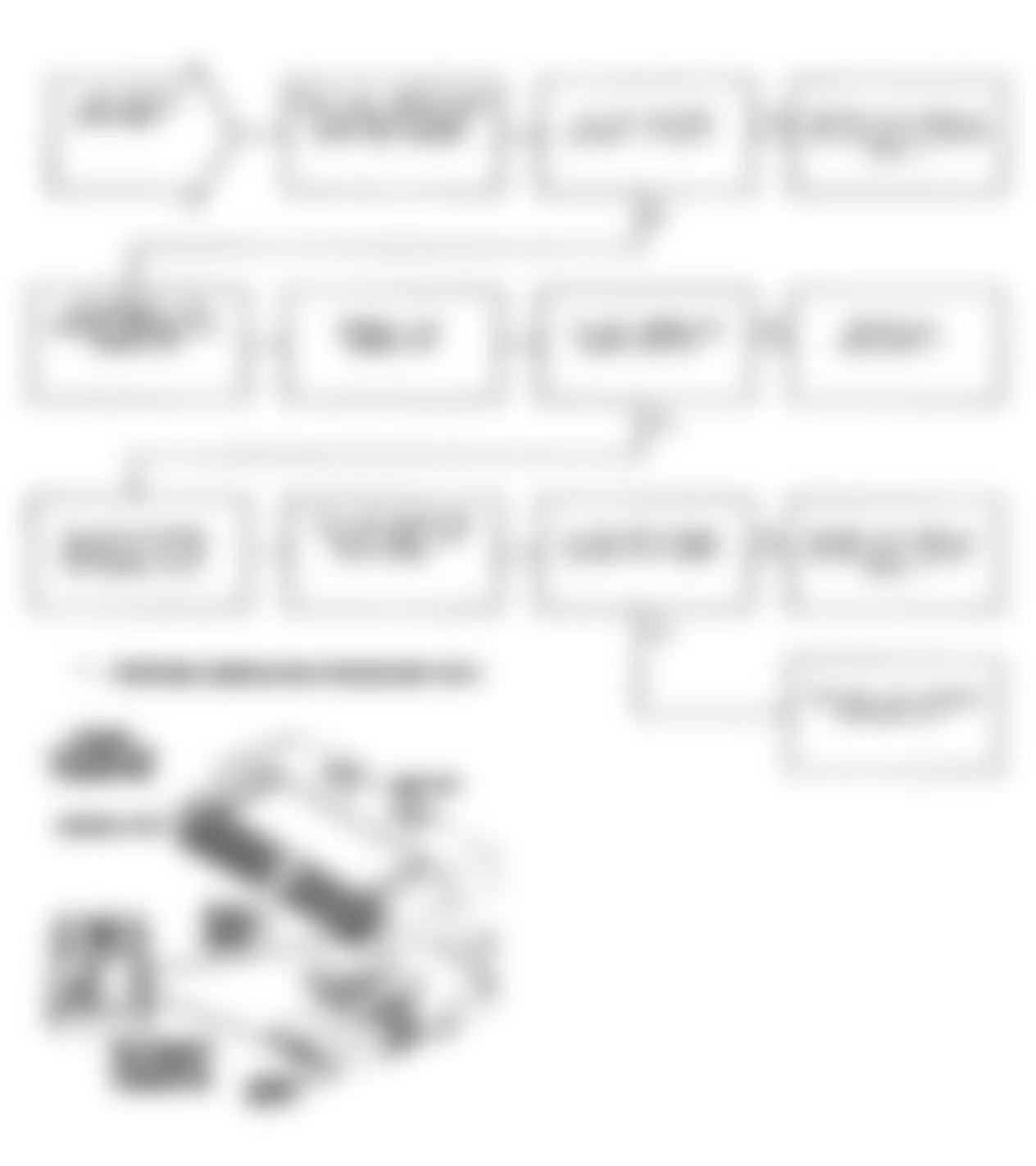
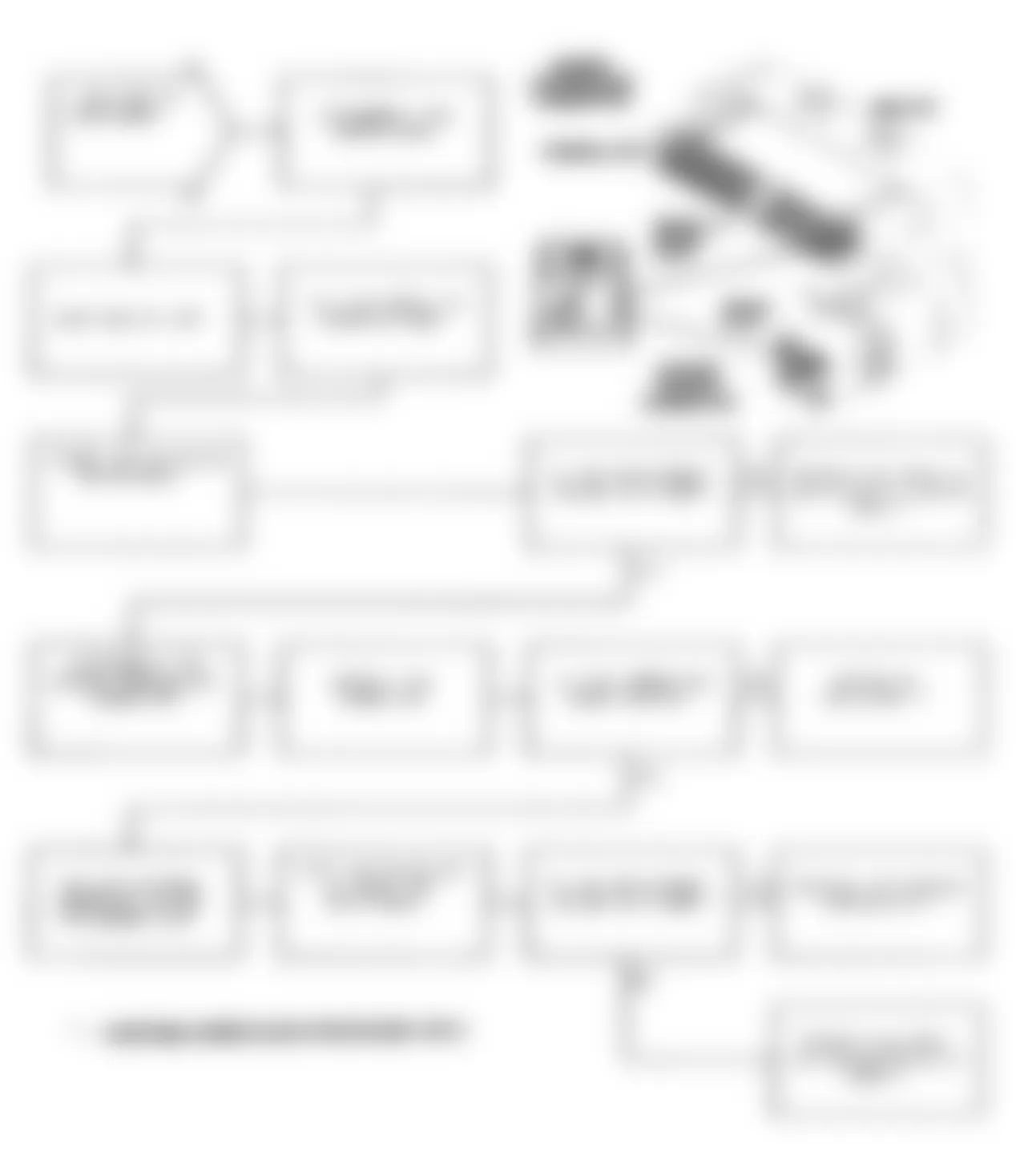
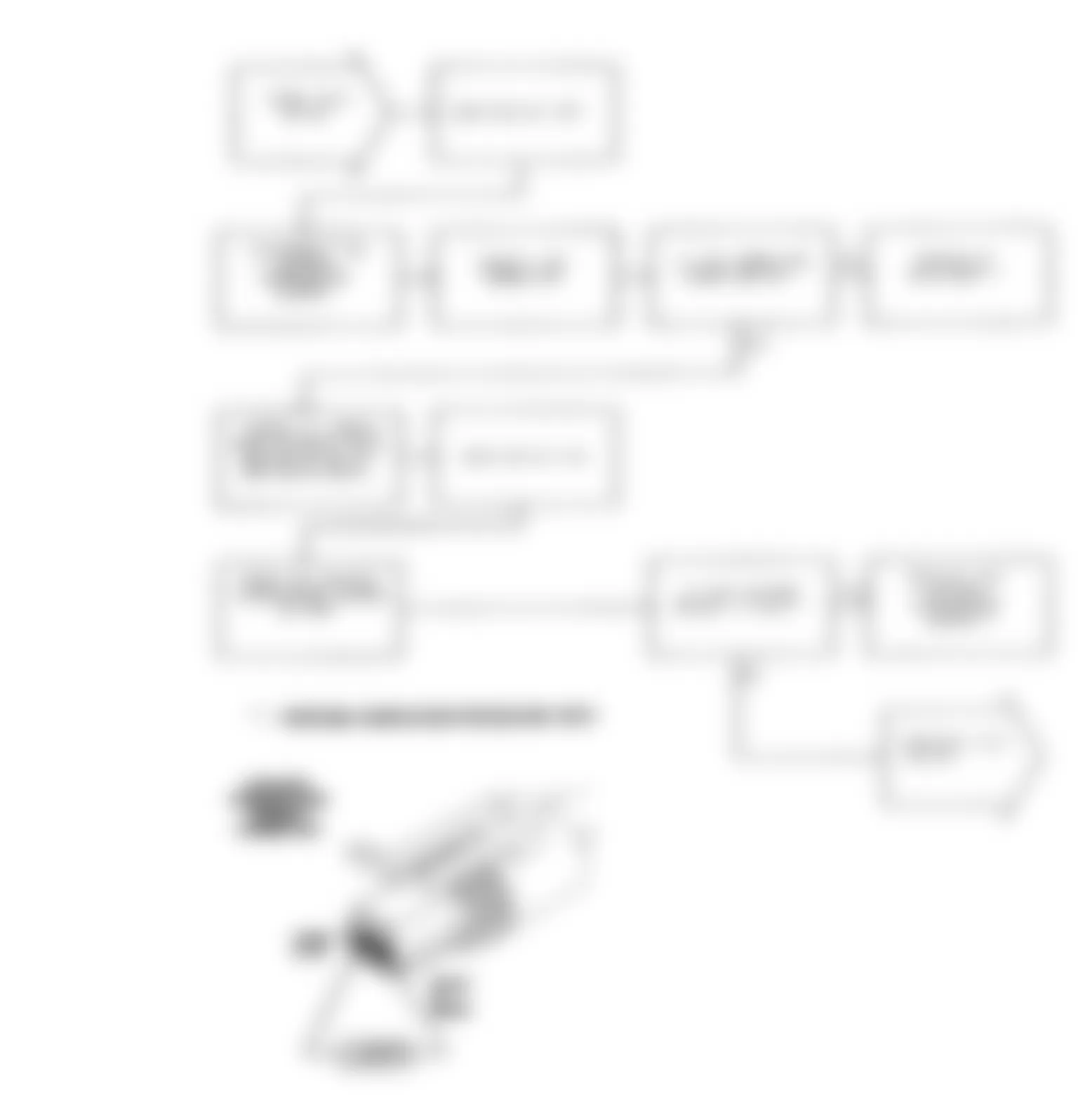
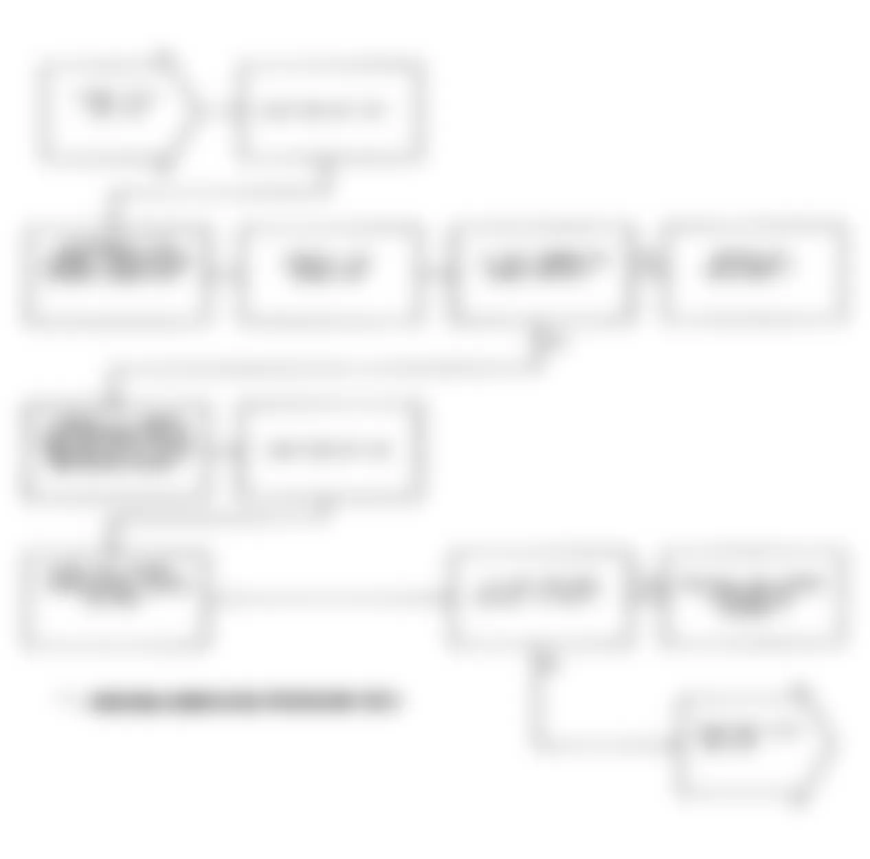
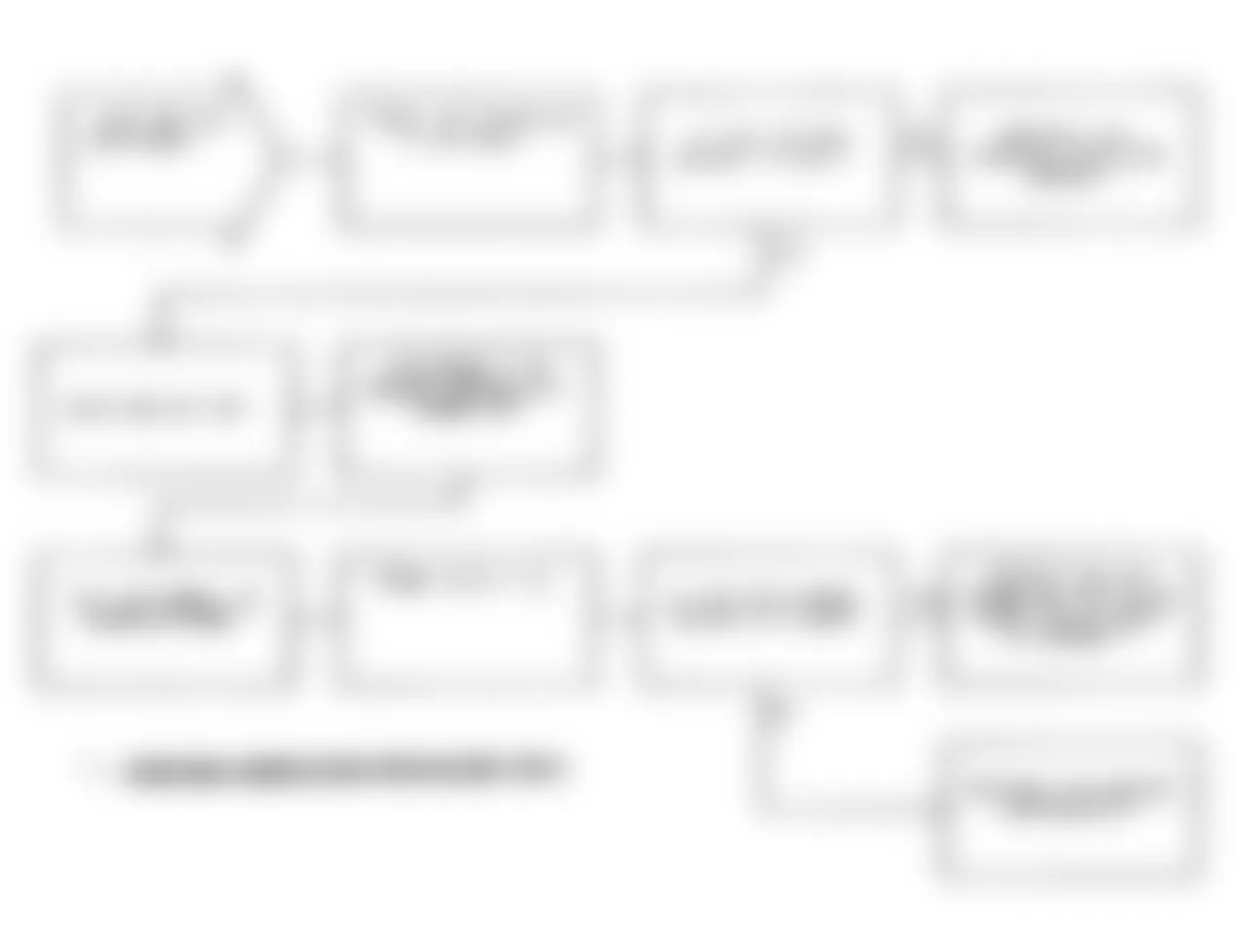
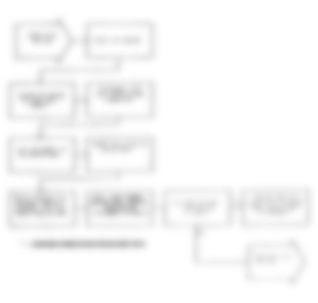
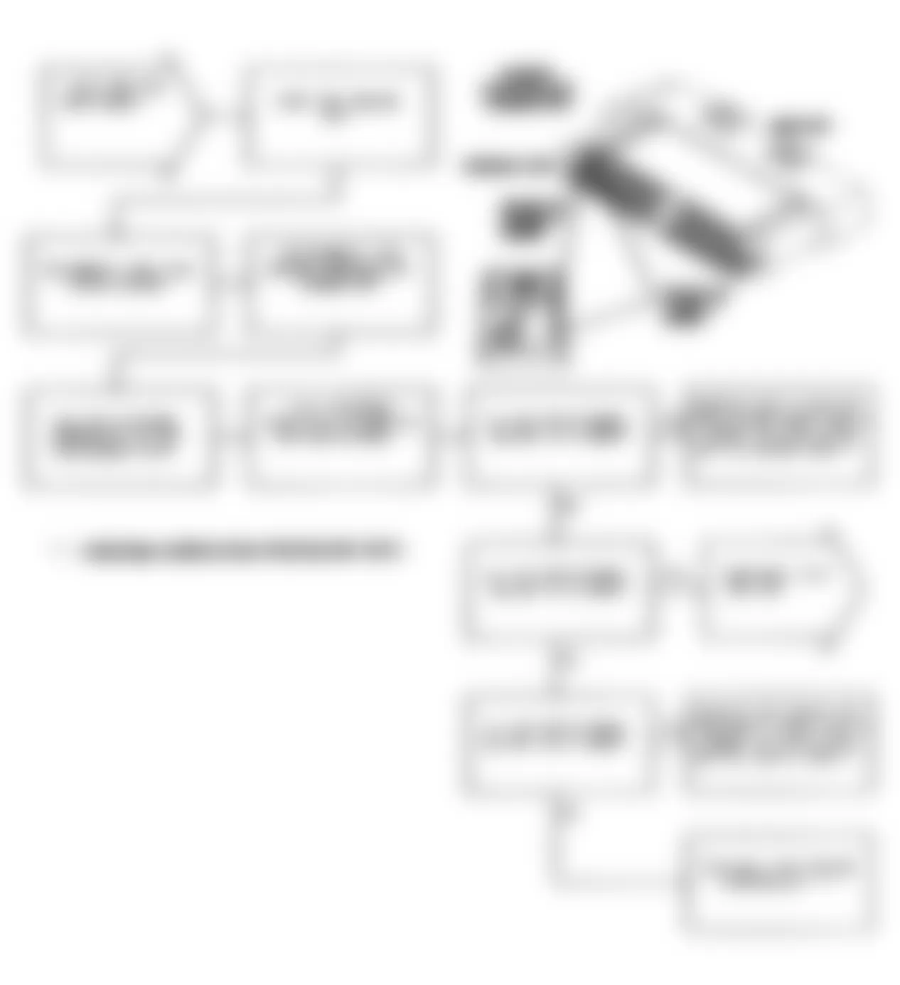
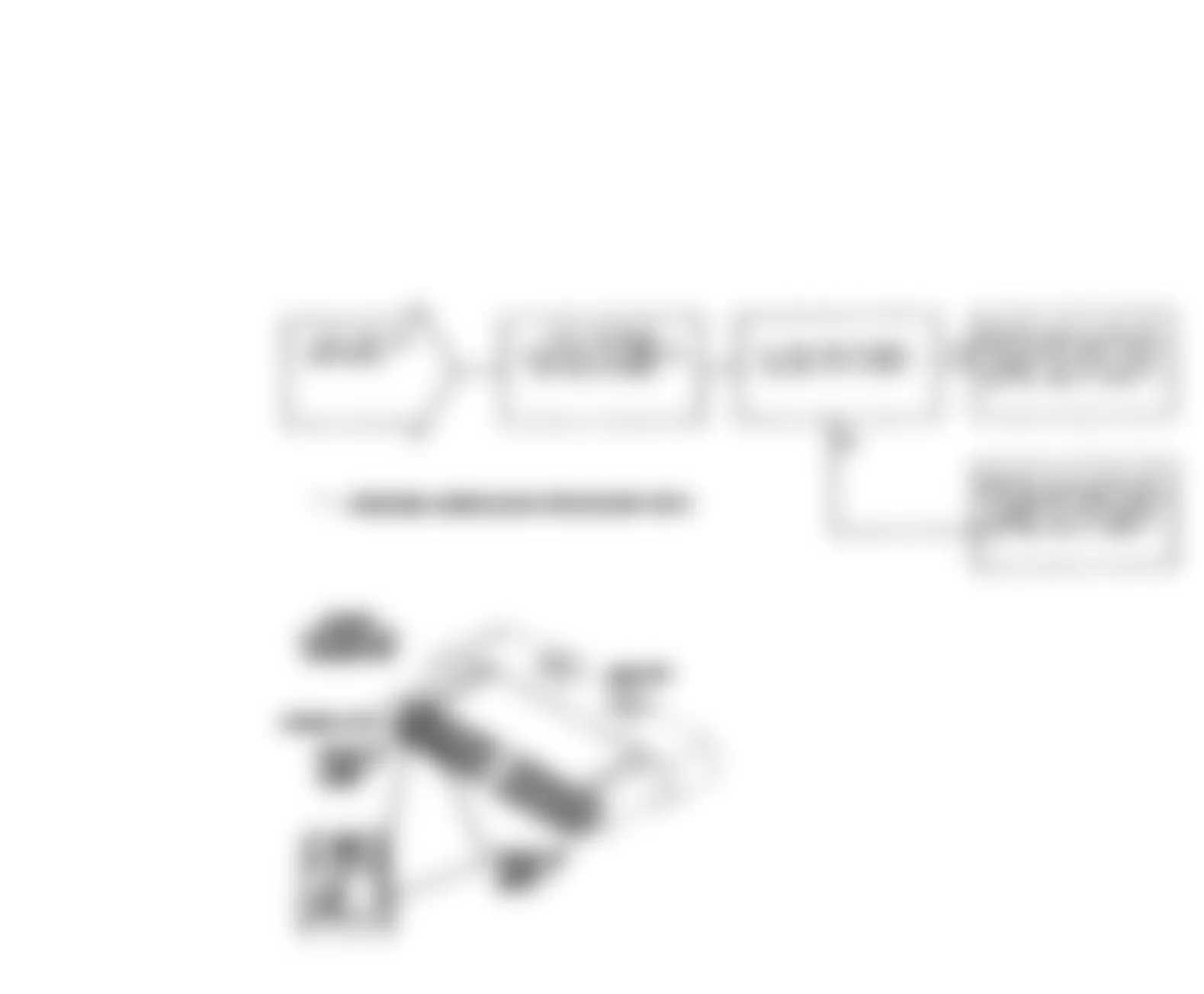
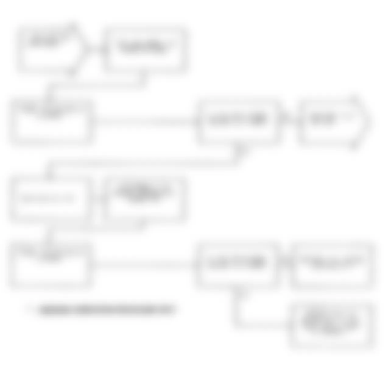
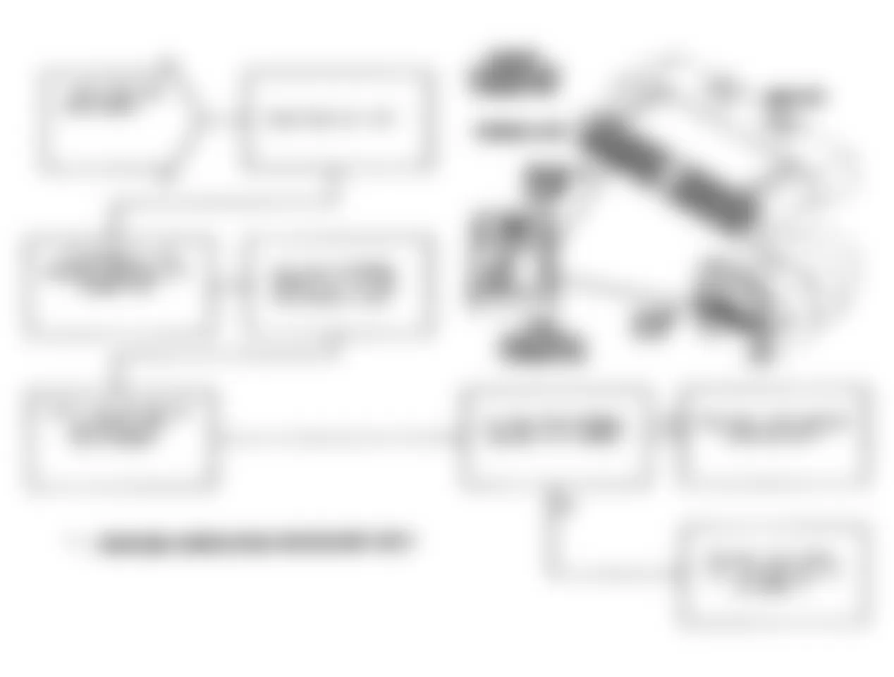
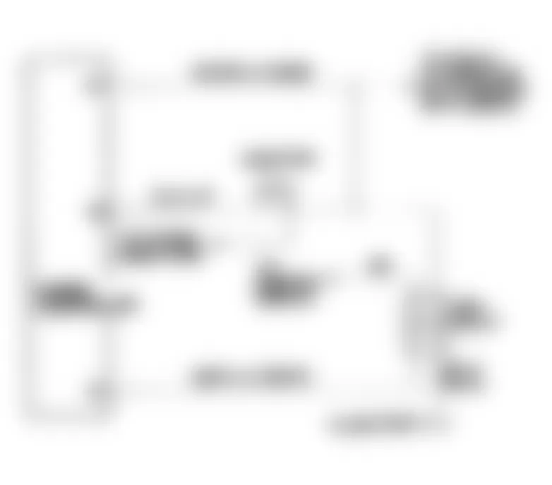
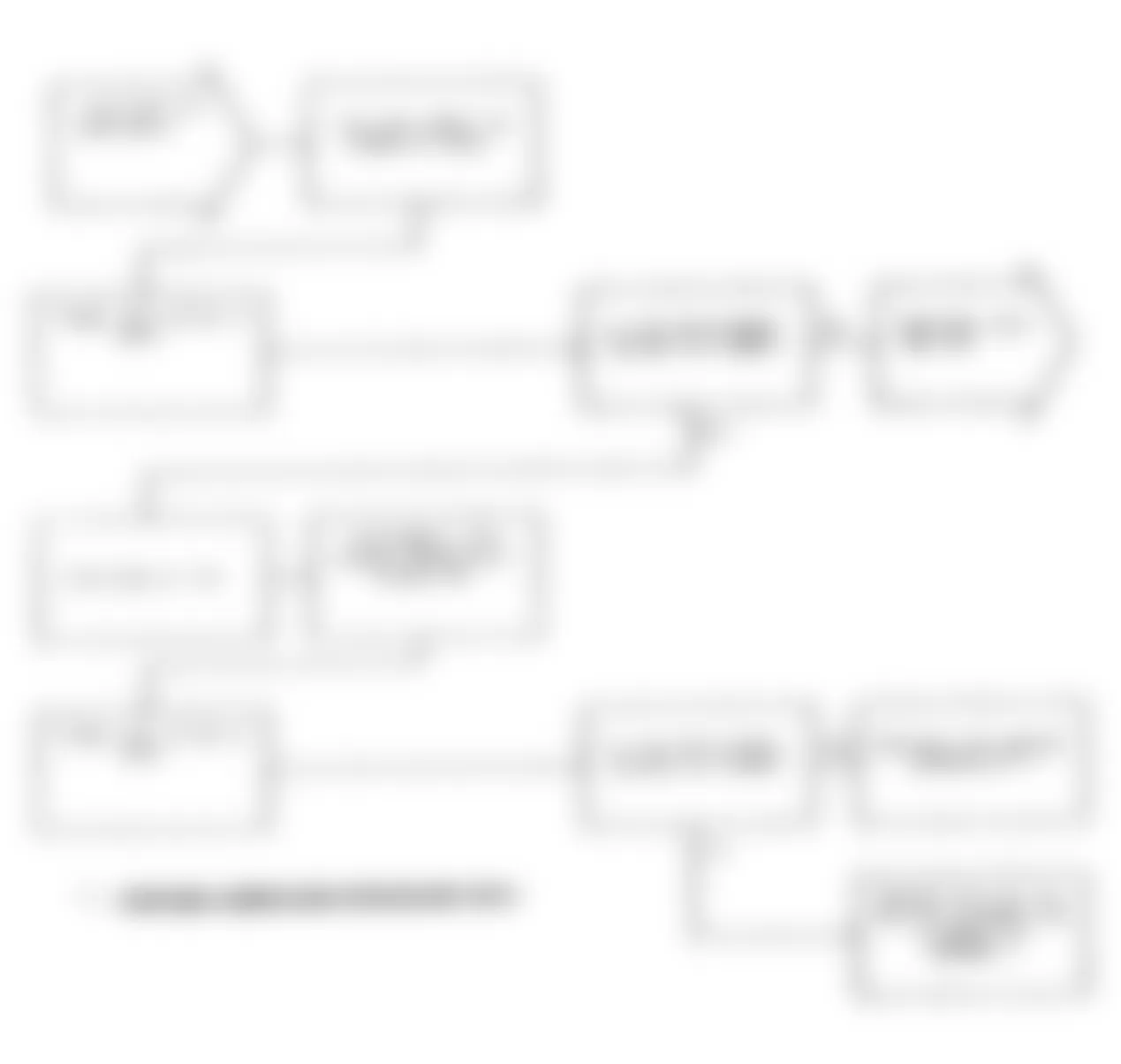
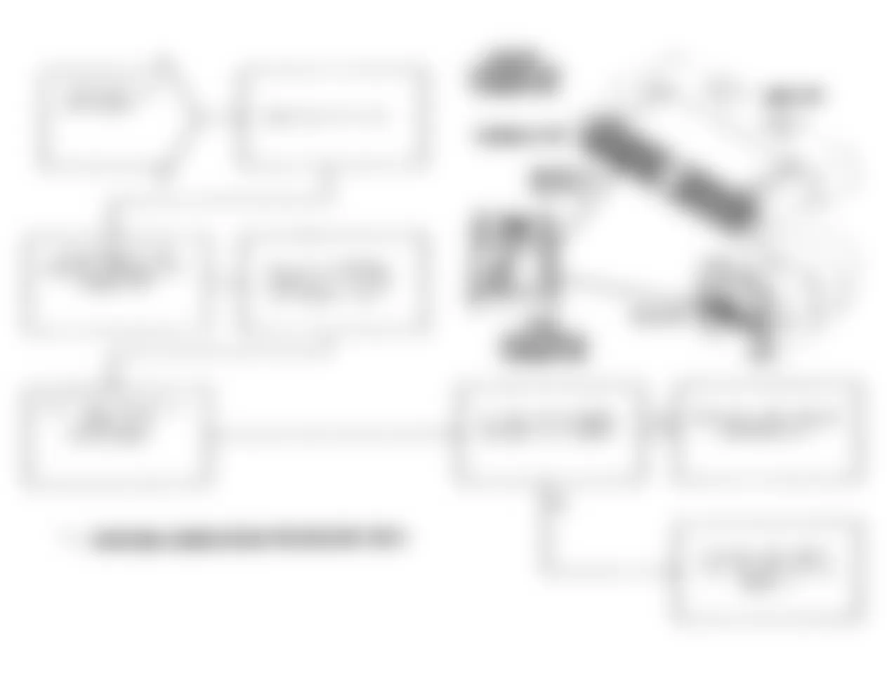
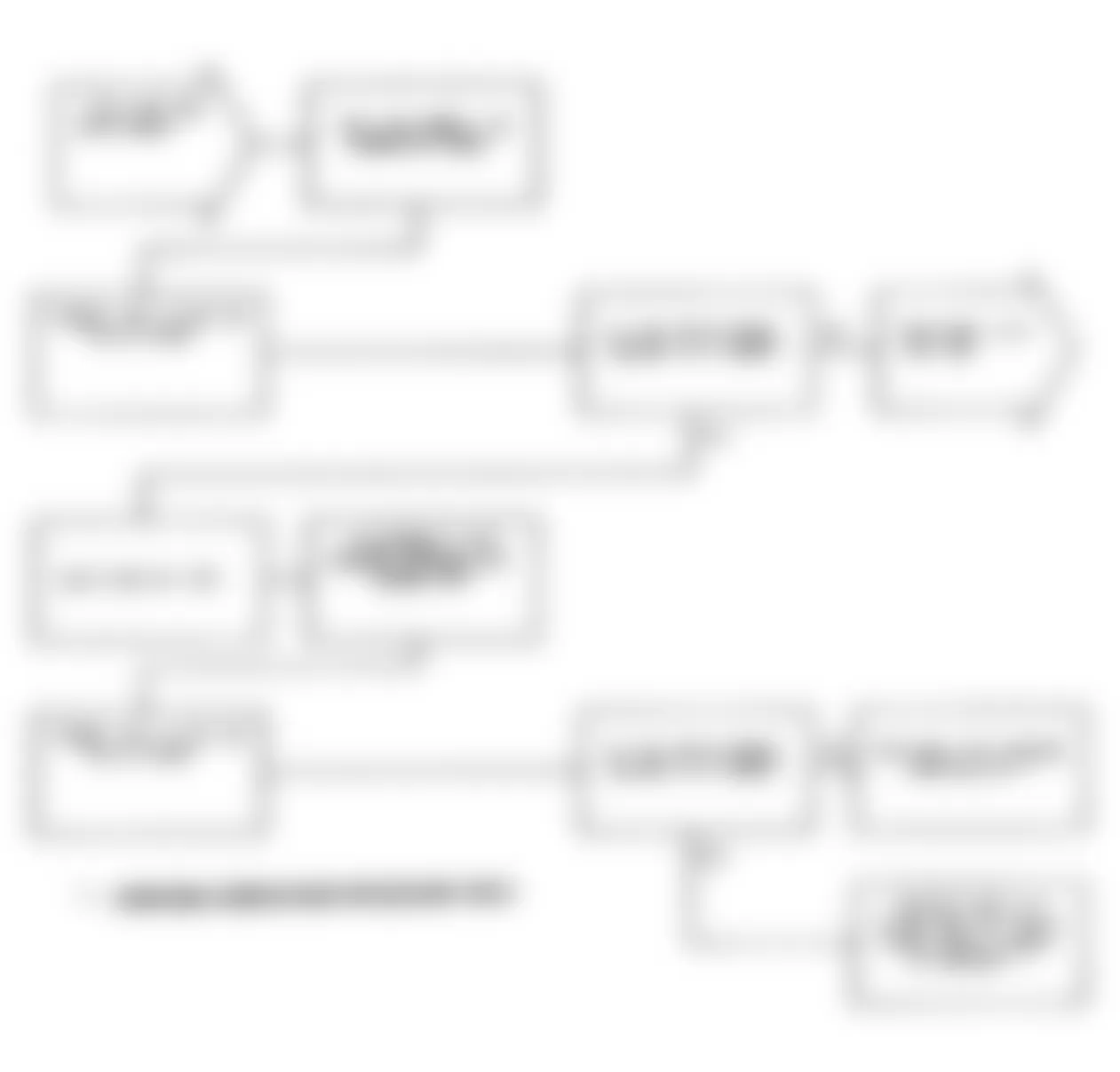
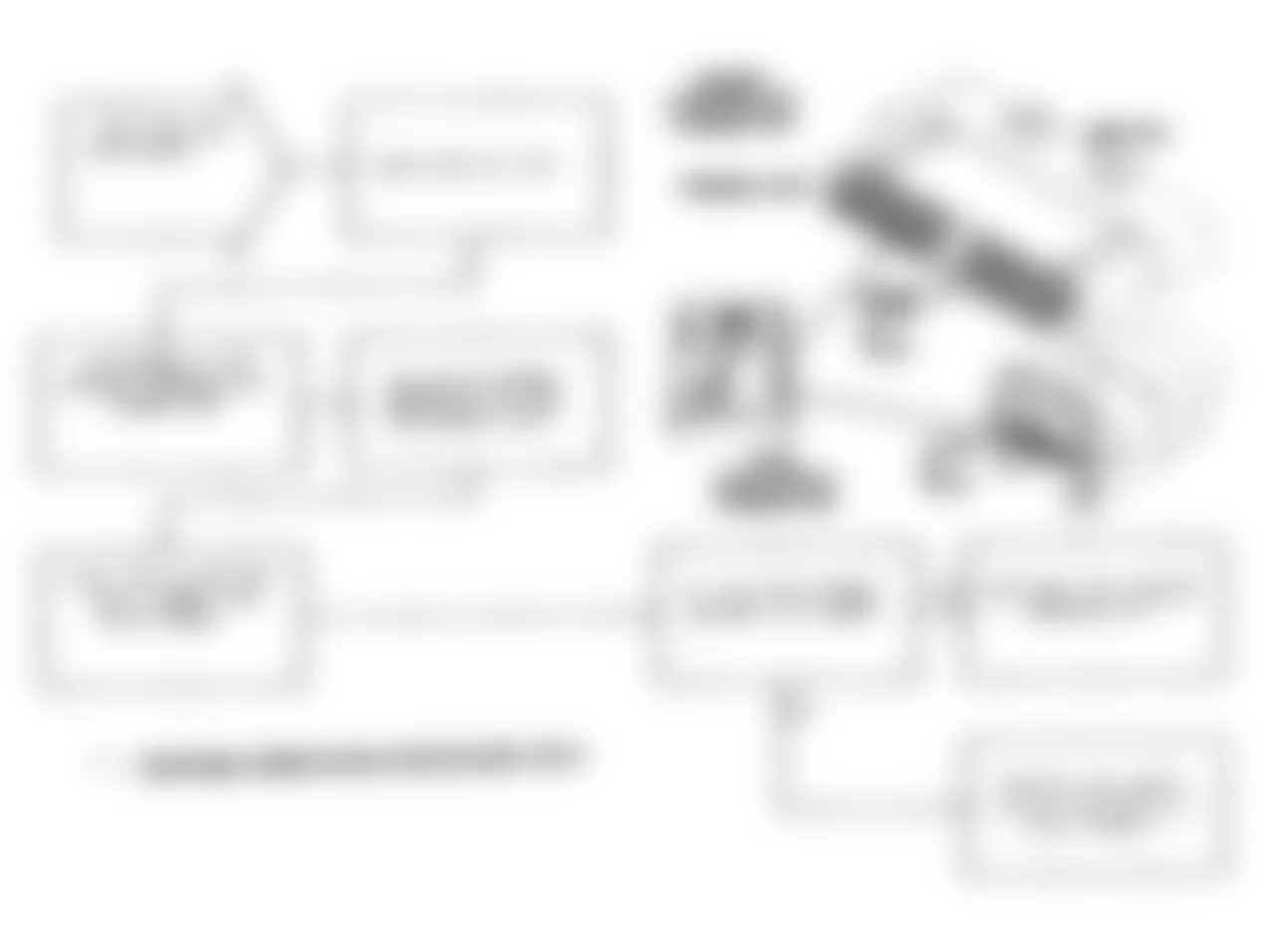
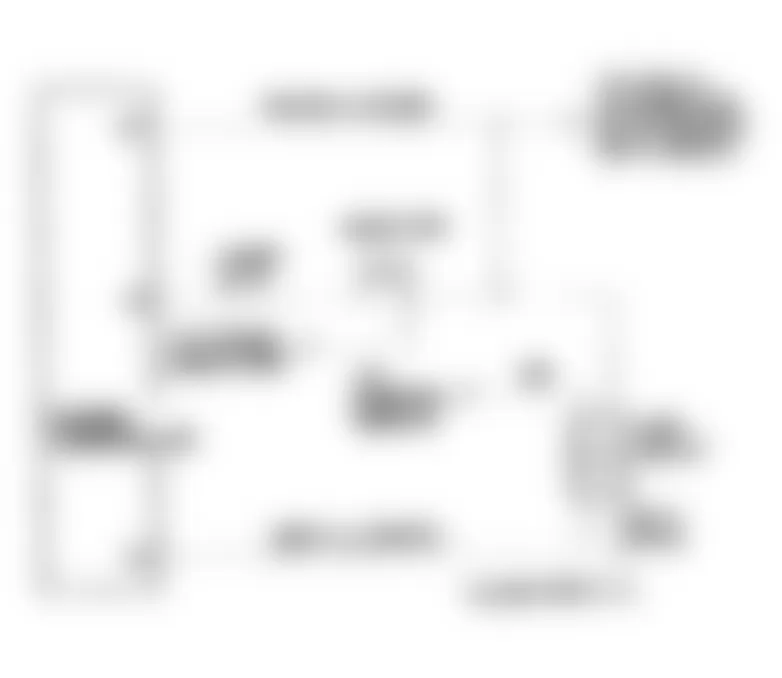
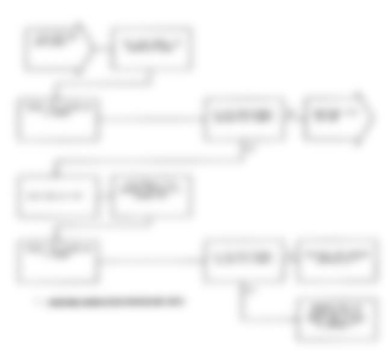
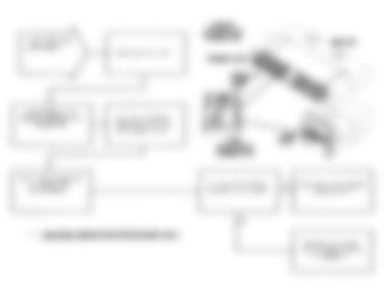
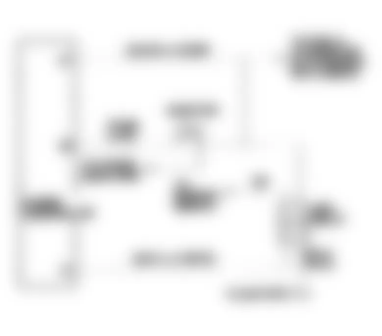
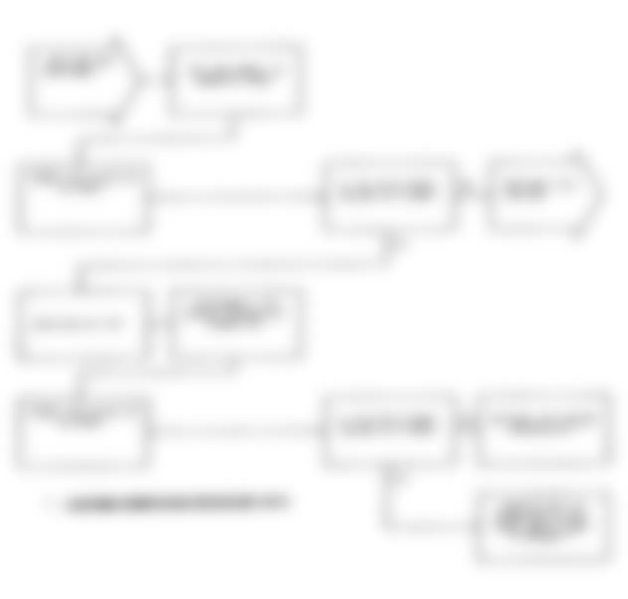
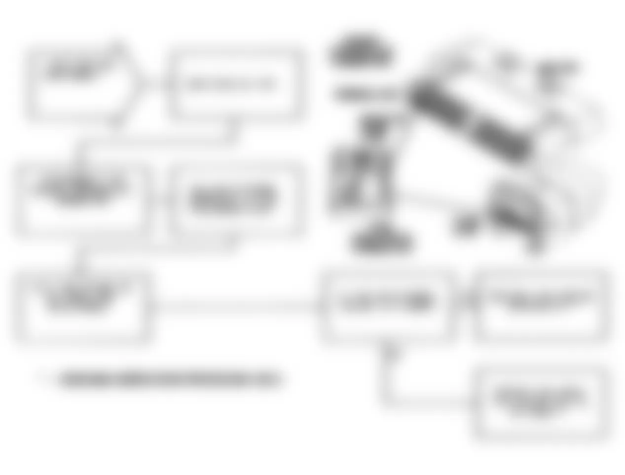
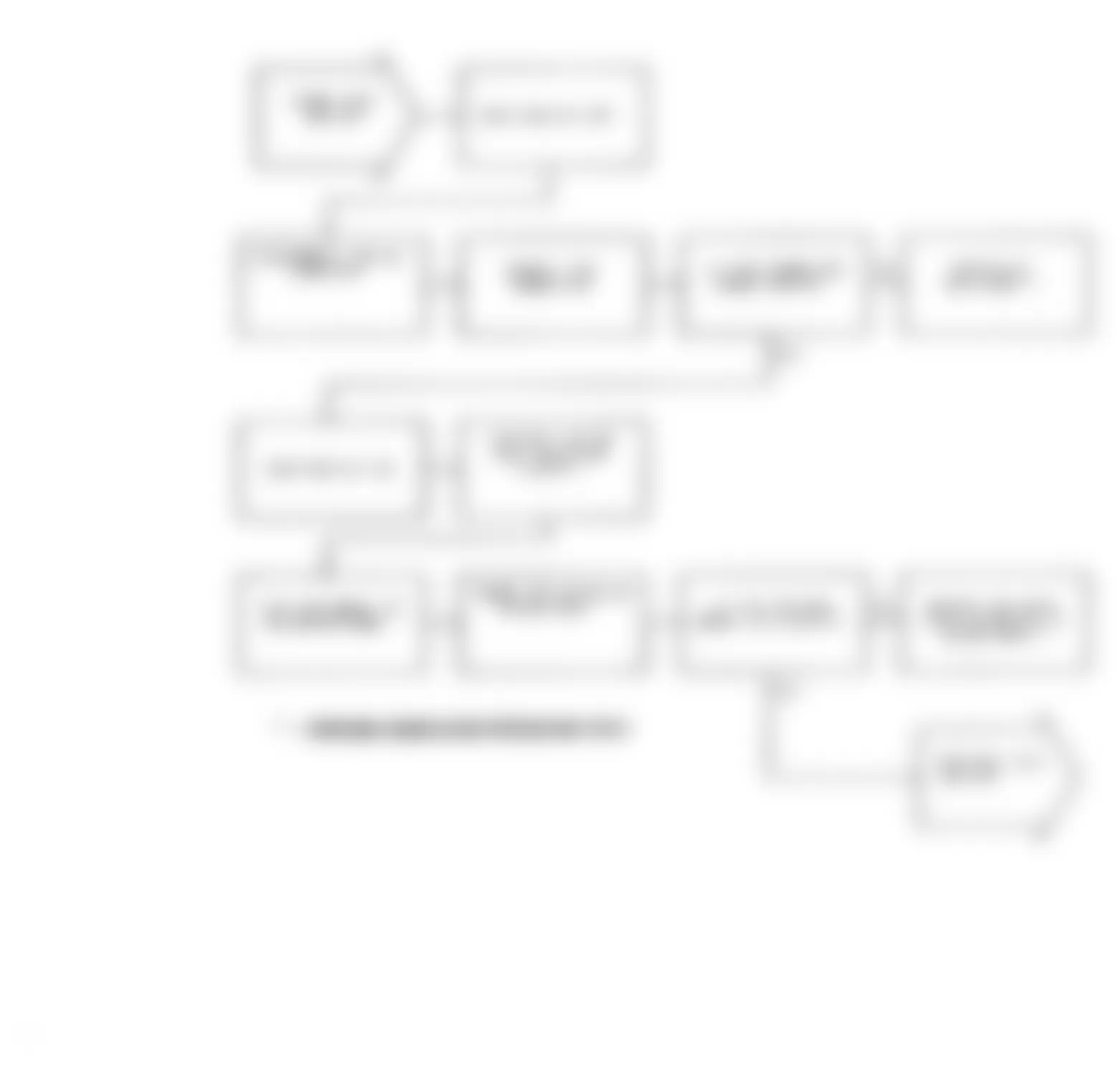
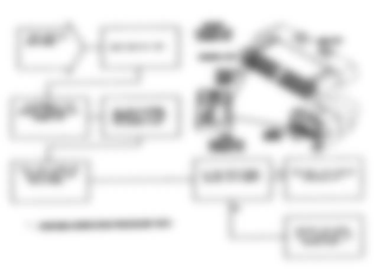
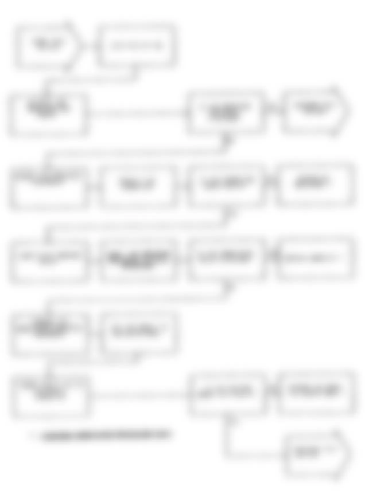
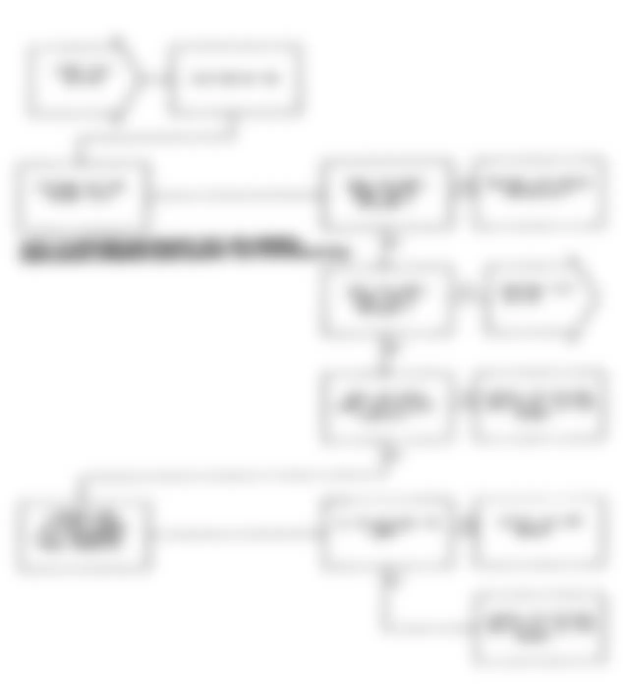
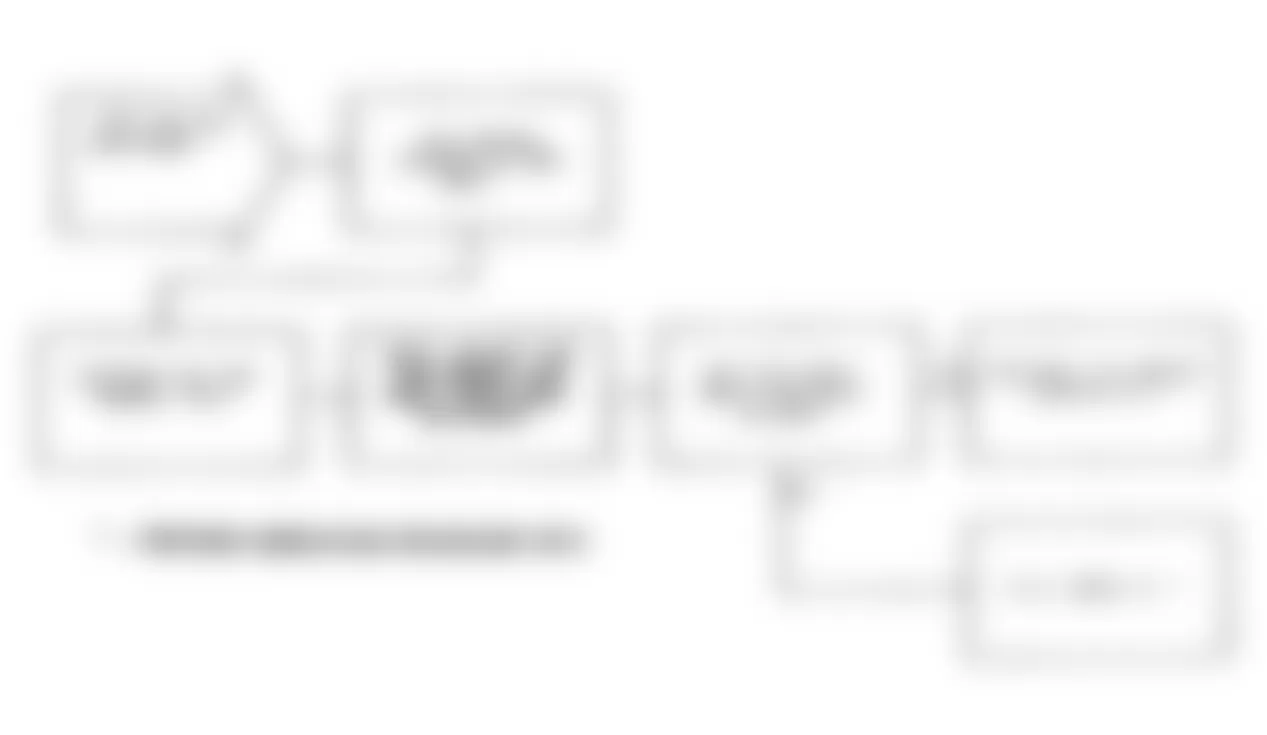
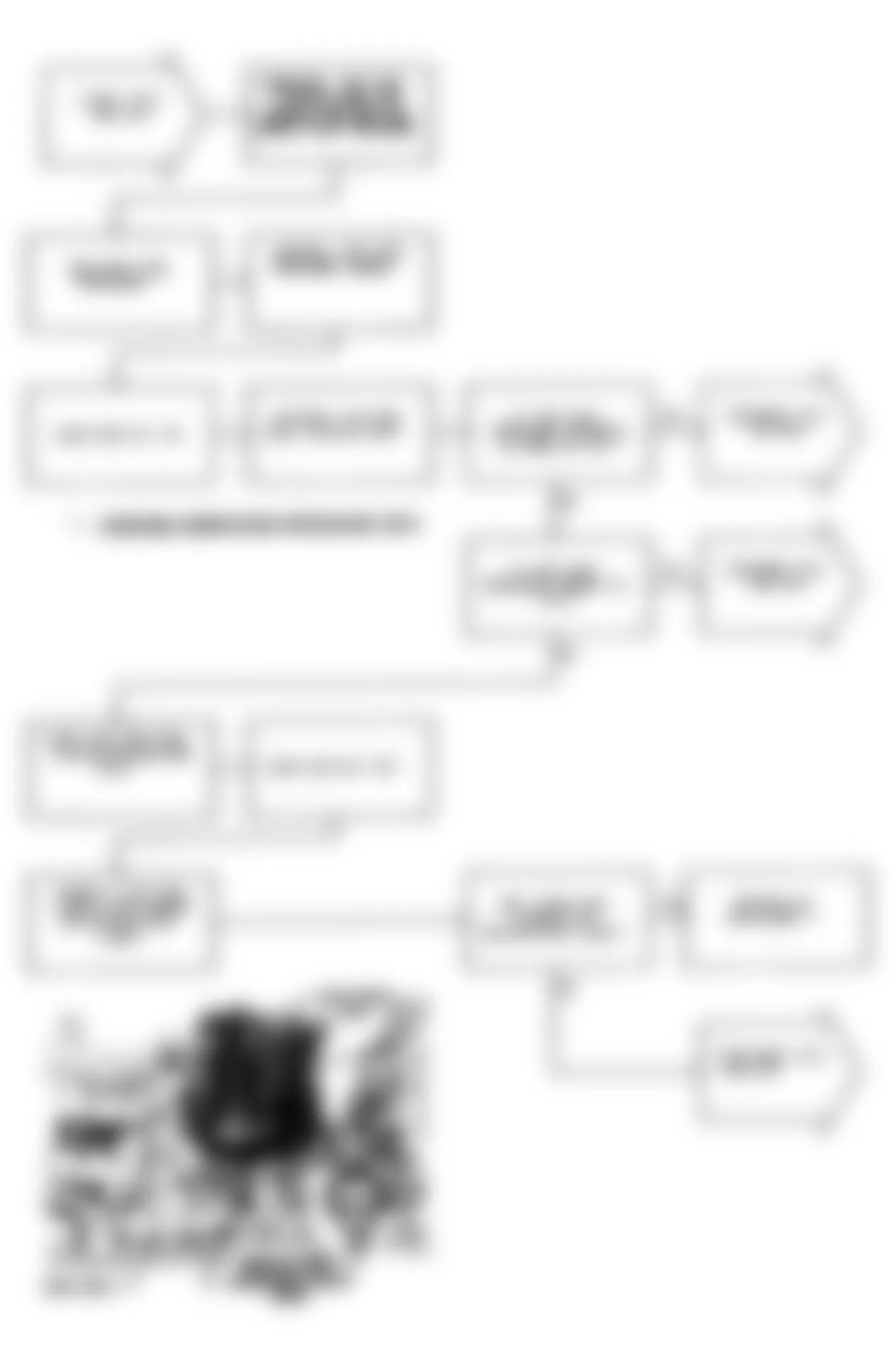
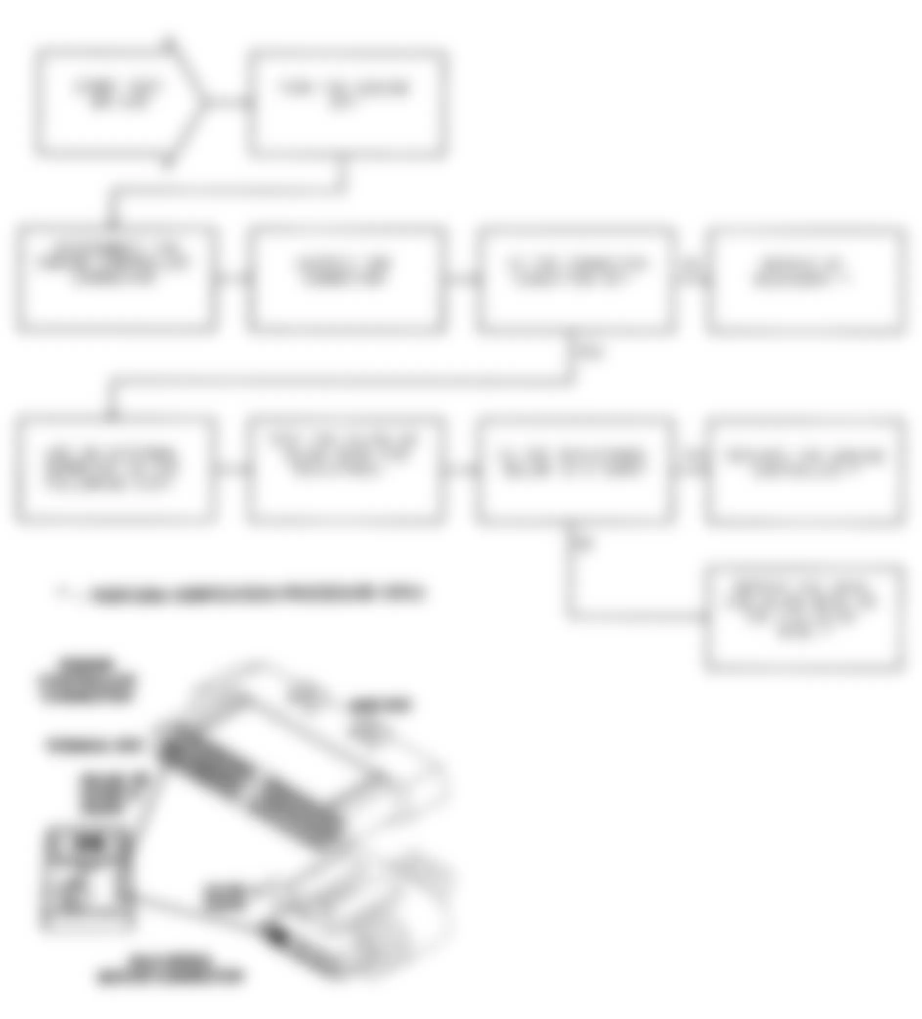
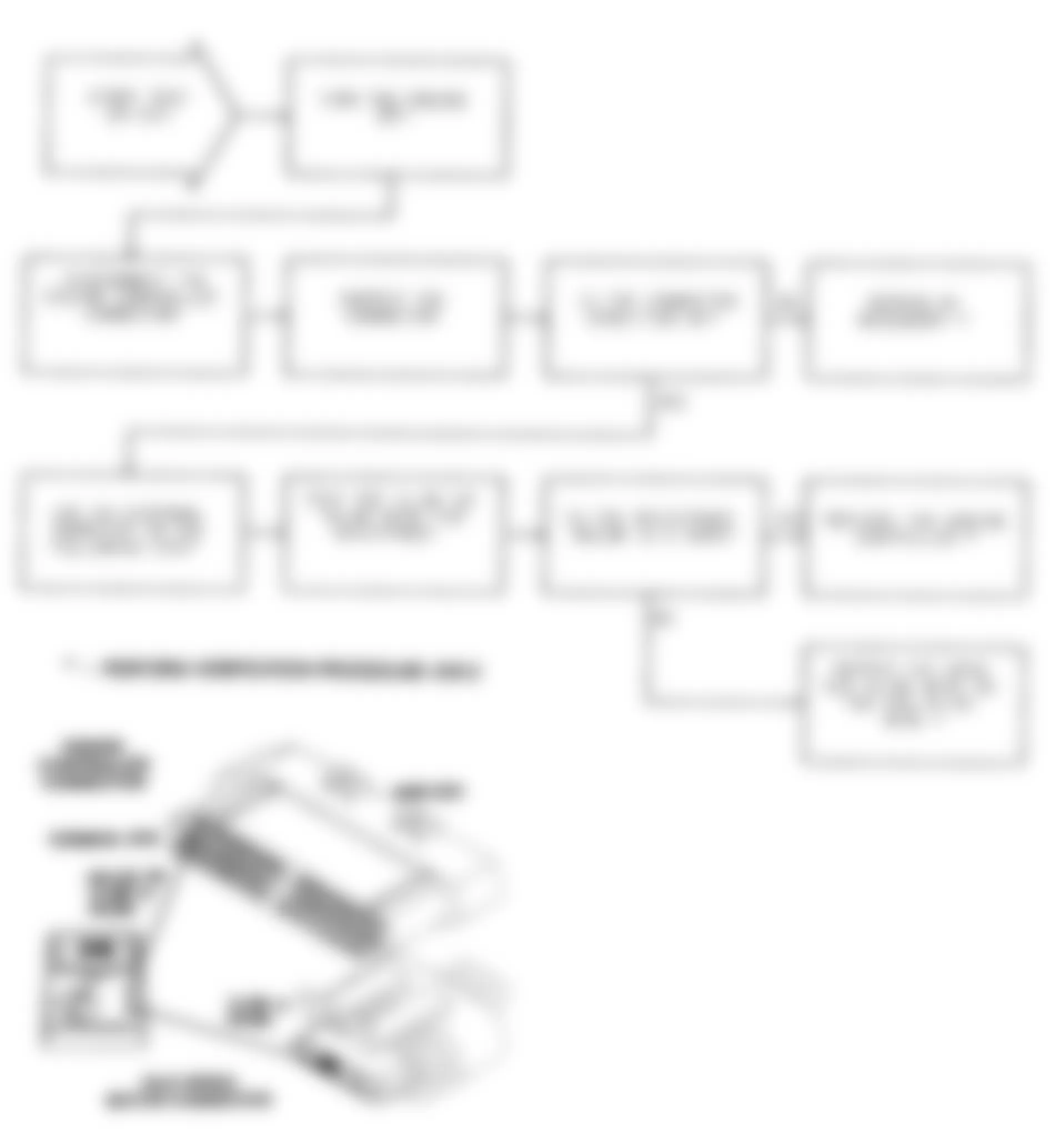
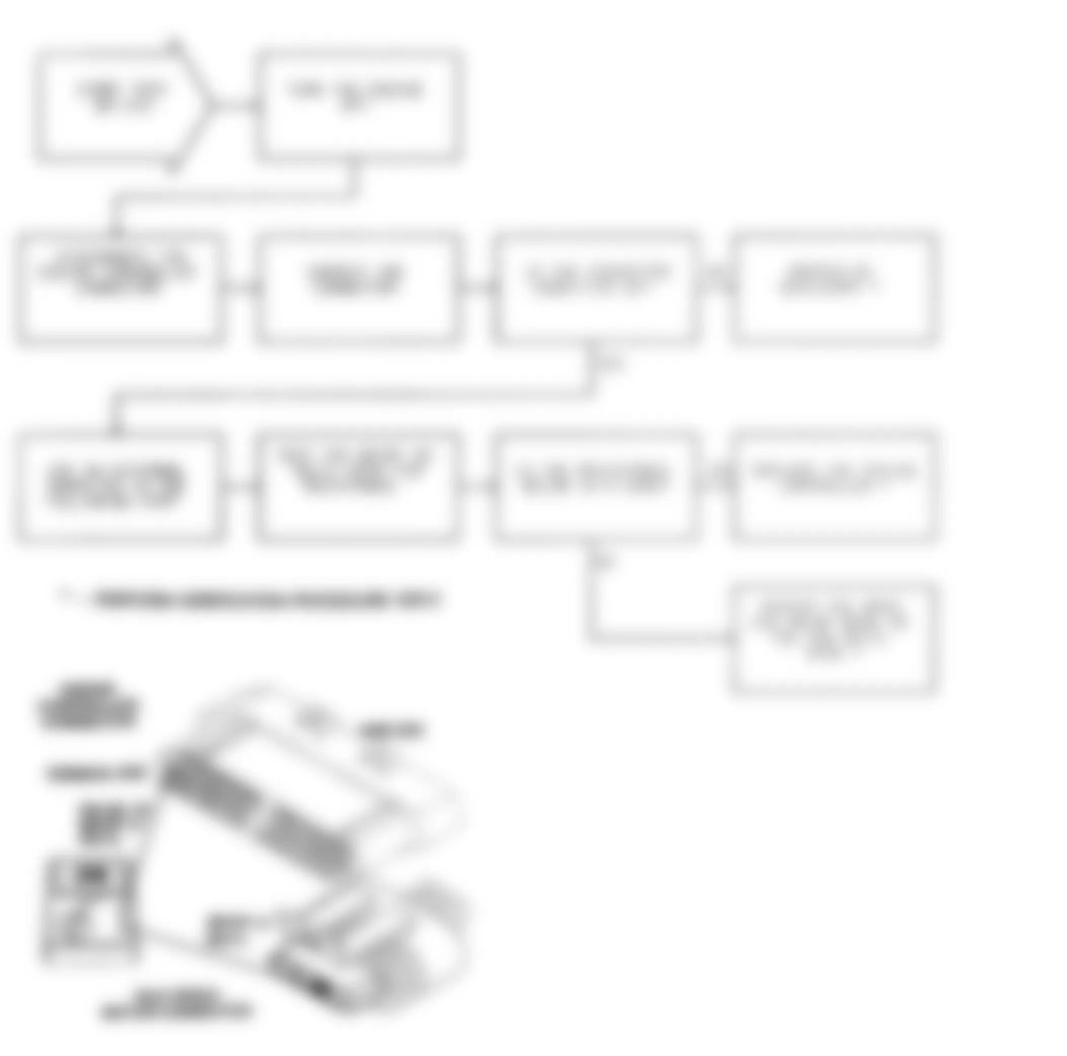
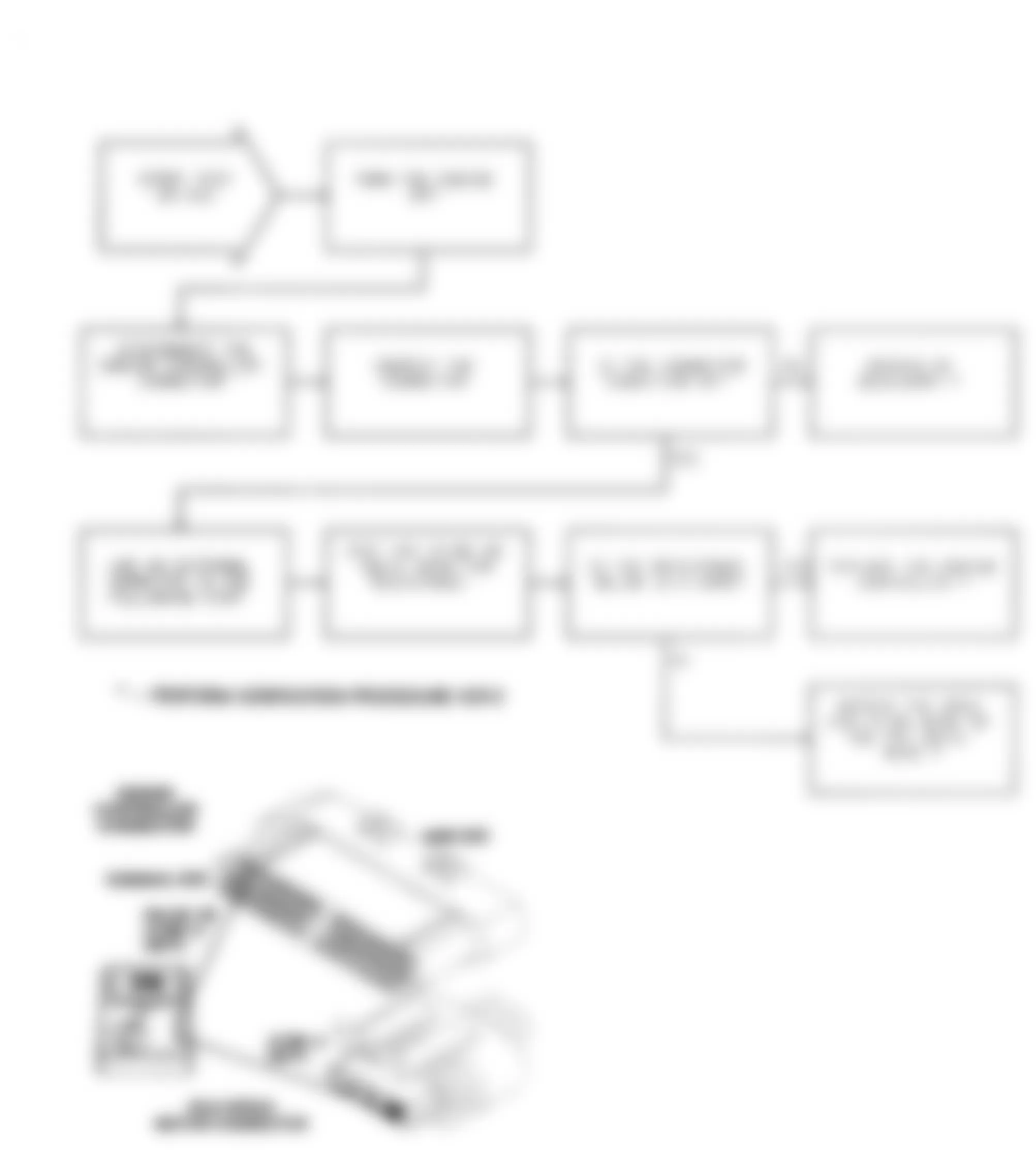
Jeep Cherokee Sport 1991 - DR-5A: REPAIRING MAP VOLTAGE TOO HIGH
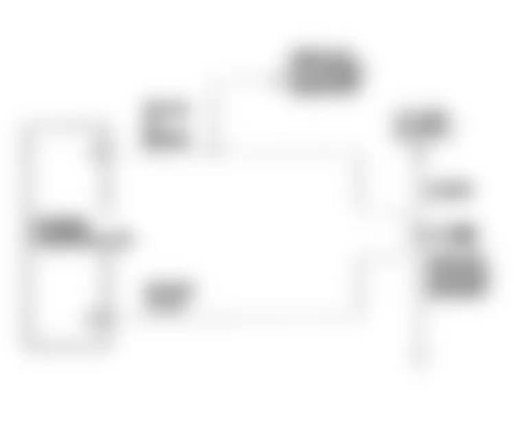
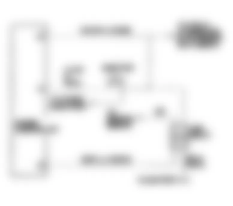
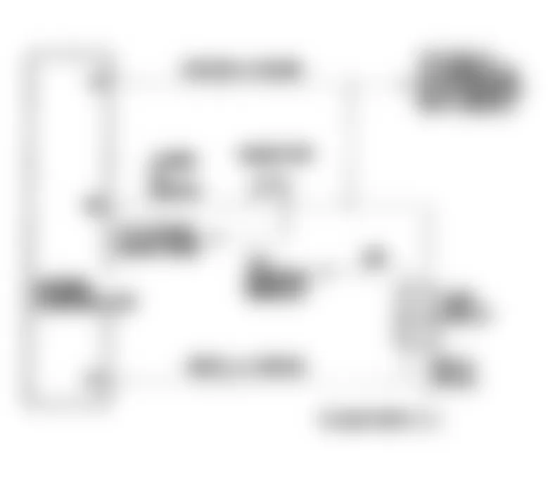
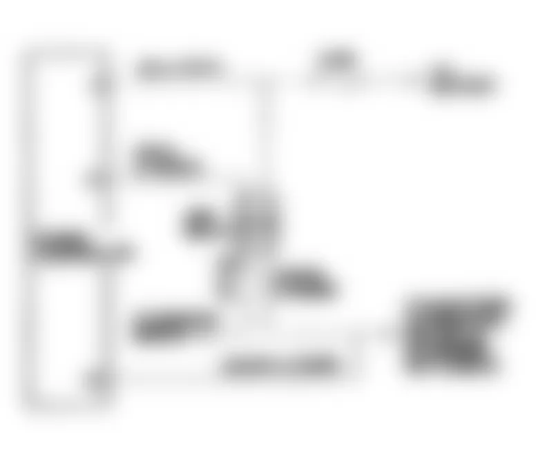
Fig. 82: Jeep Cherokee Sport 1991 - Component Locations - Test DR-5A Schematic, Map Voltage Too High
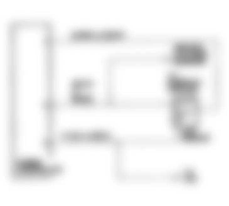
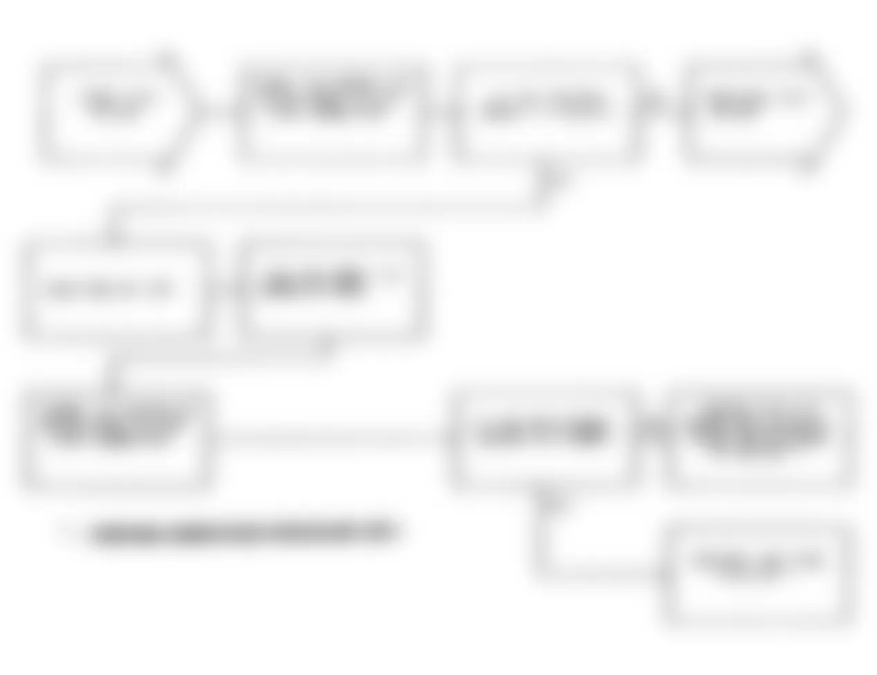
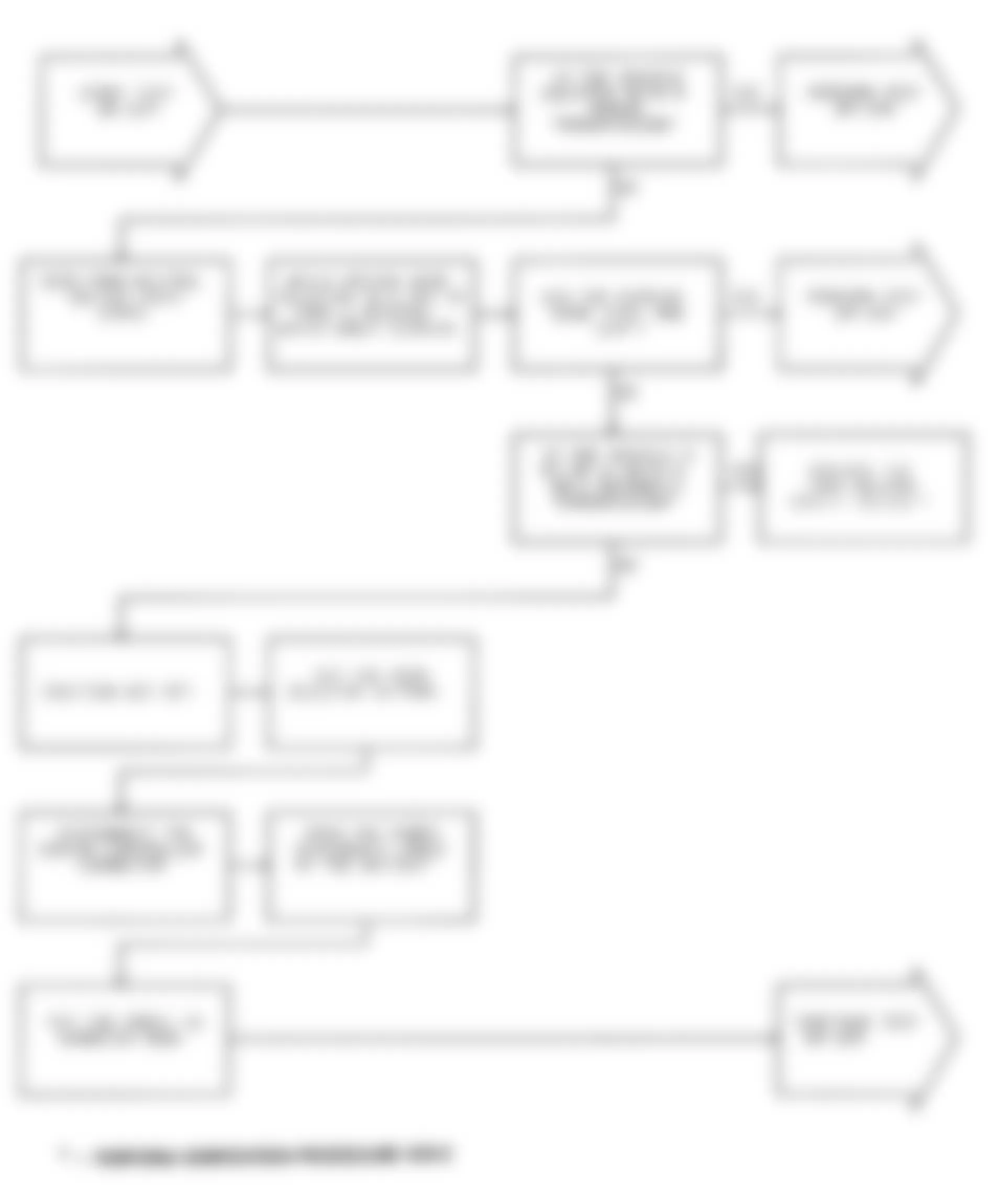
Fig. 83: Jeep Cherokee Sport 1991 - Component Locations - Test DR-5A (1 of 2) Map Voltage Too High
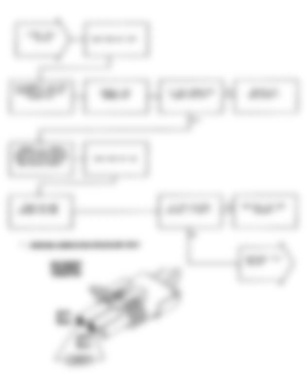
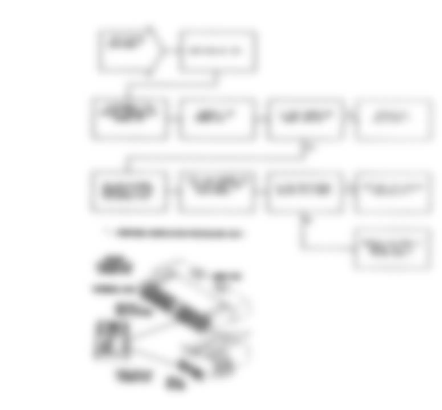
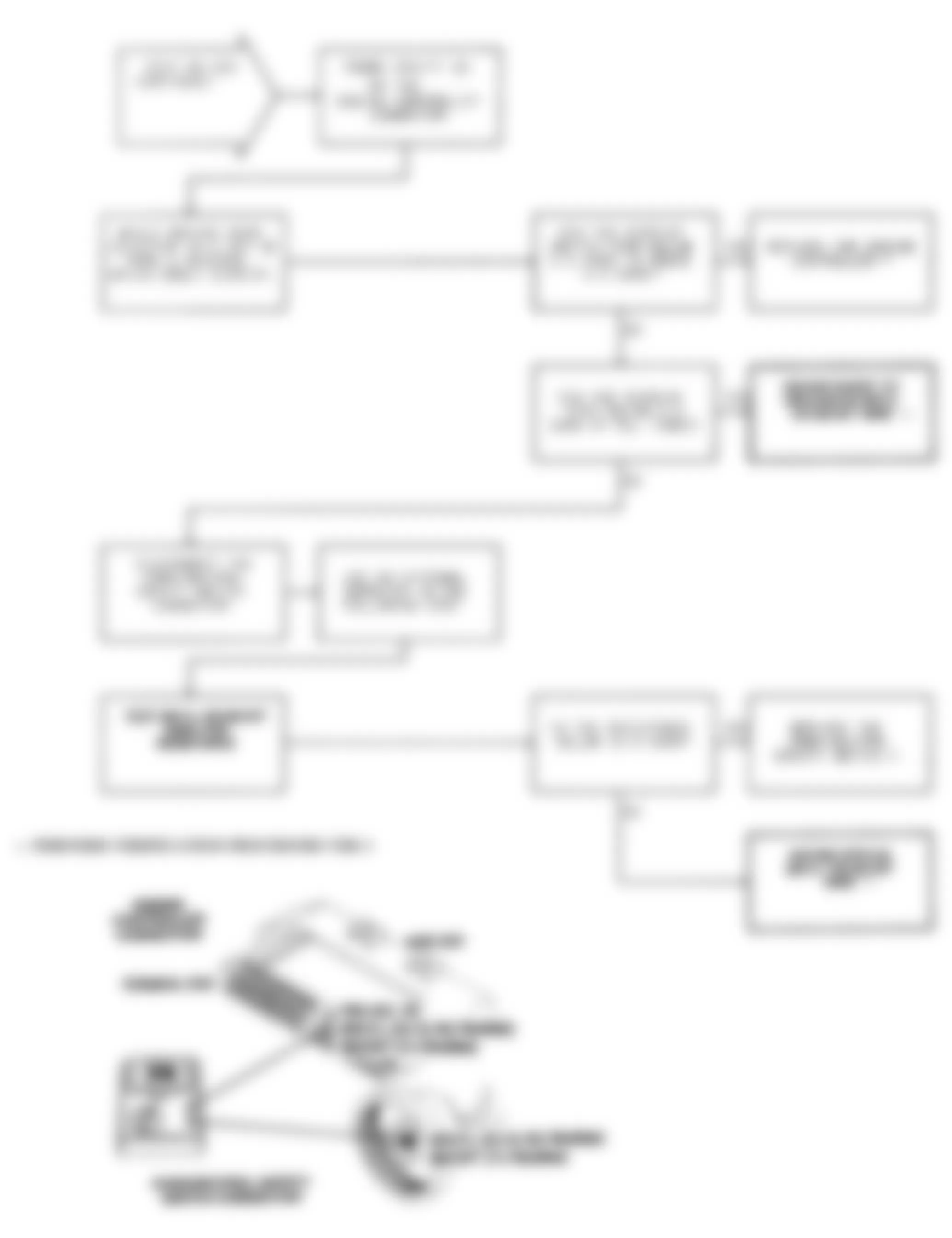
Fig. 84: Jeep Cherokee Sport 1991 - Component Locations - Test DR-5A Voltage Too High
Jeep Cherokee Sport 1991 - DR-6A: REPAIRING NO VEHICLE SPEED SIGNAL

Jeep Cherokee Sport 1991 - DR-7A: REPAIRING O2 SIGNAL STAYS AT CENTER

Jeep Cherokee Sport 1991 - DR-8A: REPAIRING O2 SIGNAL SHORTED TO VOLTAGE
Jeep Cherokee Sport 1991 - DR-9A: REPAIRING COOLANT SENSOR VOLTAGE TOO HIGH

Jeep Cherokee Sport 1991 - DR-10A: REPAIRING COOLANT SENSOR VOLTAGE TOO LOW
Jeep Cherokee Sport 1991 - DR-11A: REPAIRING CHARGE TEMPERATURE SENSOR VOLTAGE HIGH

Jeep Cherokee Sport 1991 - DR-12A: REPAIRING CHARGE TEMPERATURE SENSOR VOLTAGE LOW
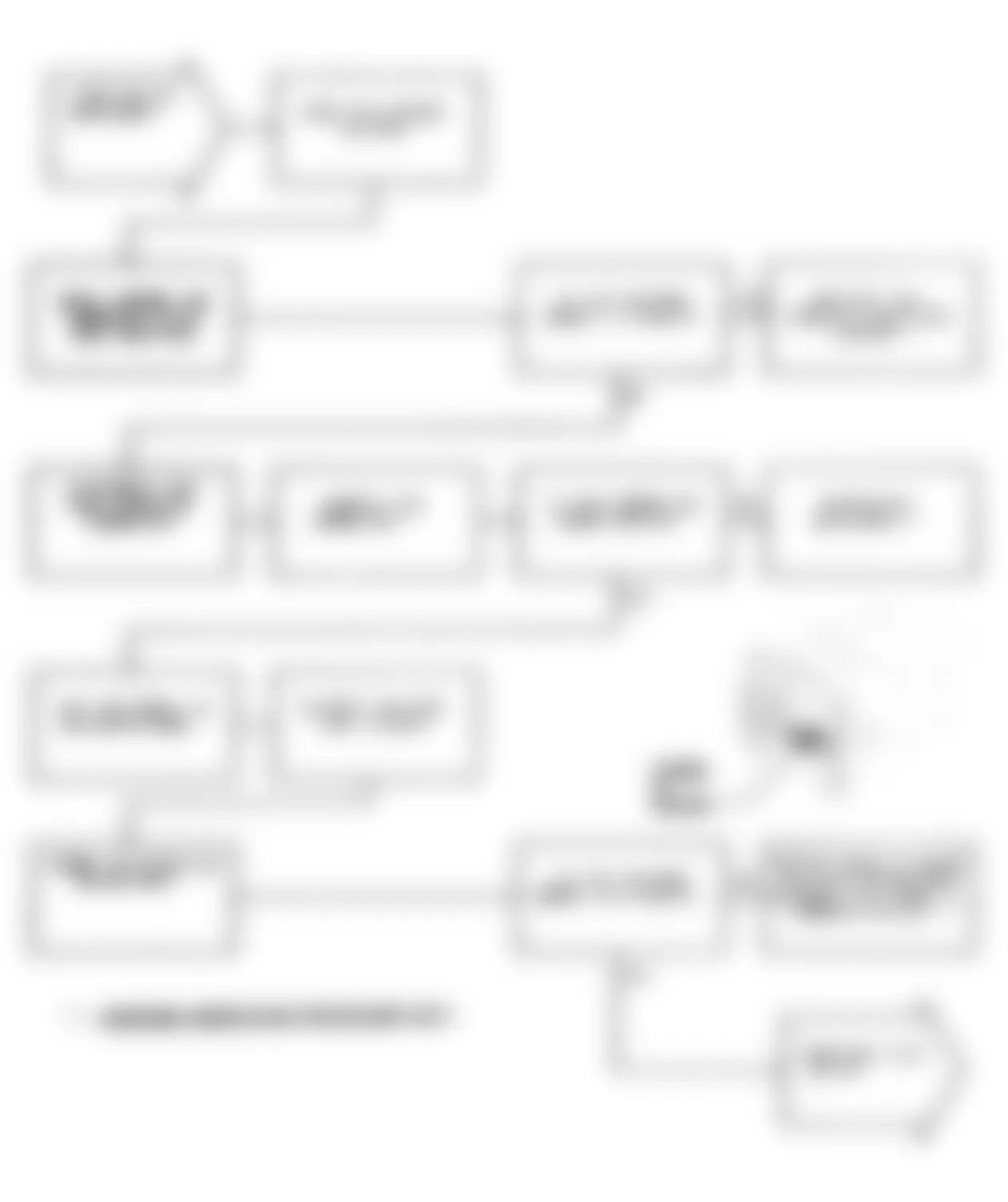
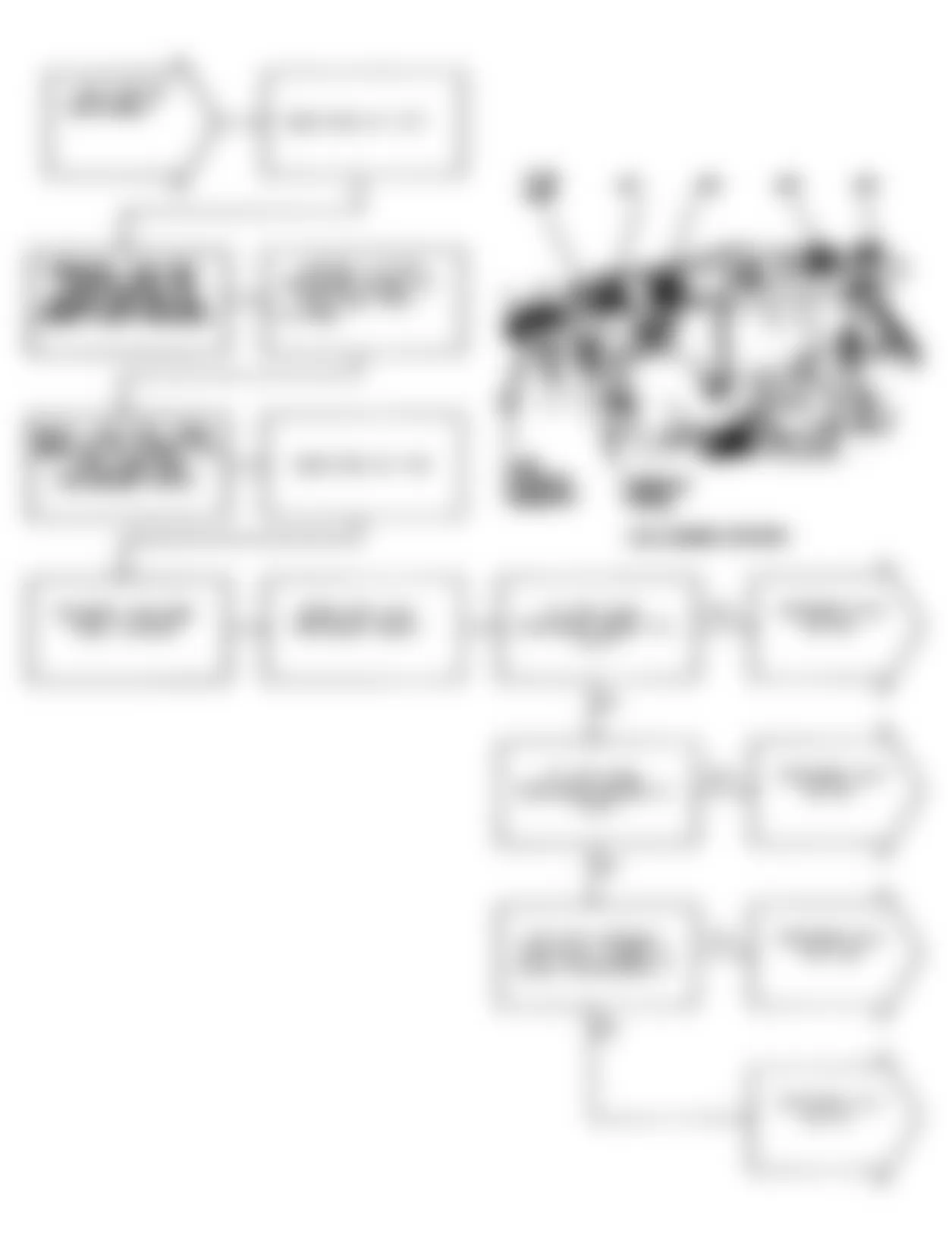
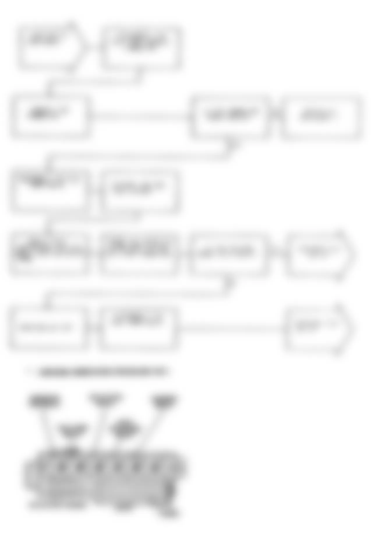
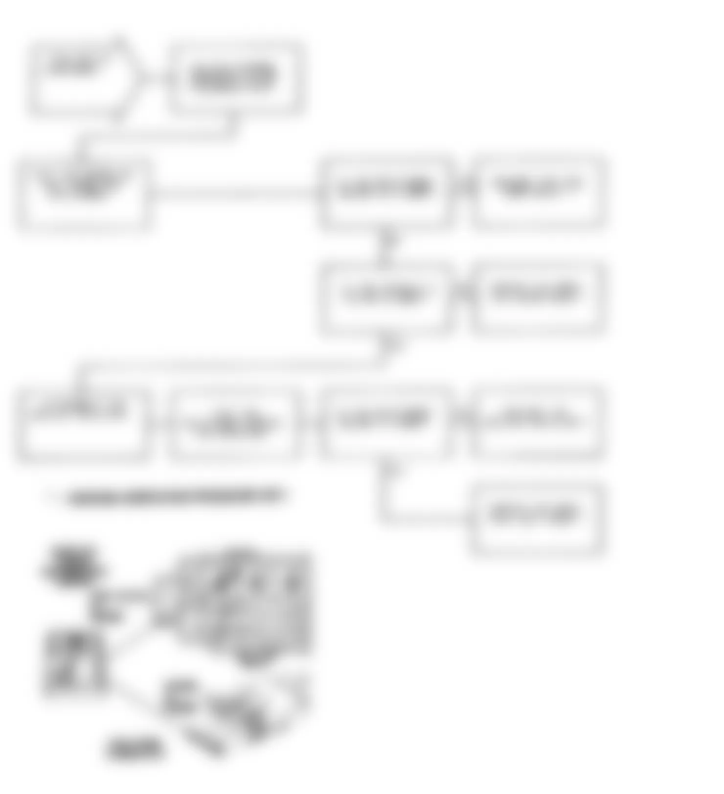
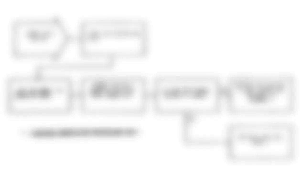
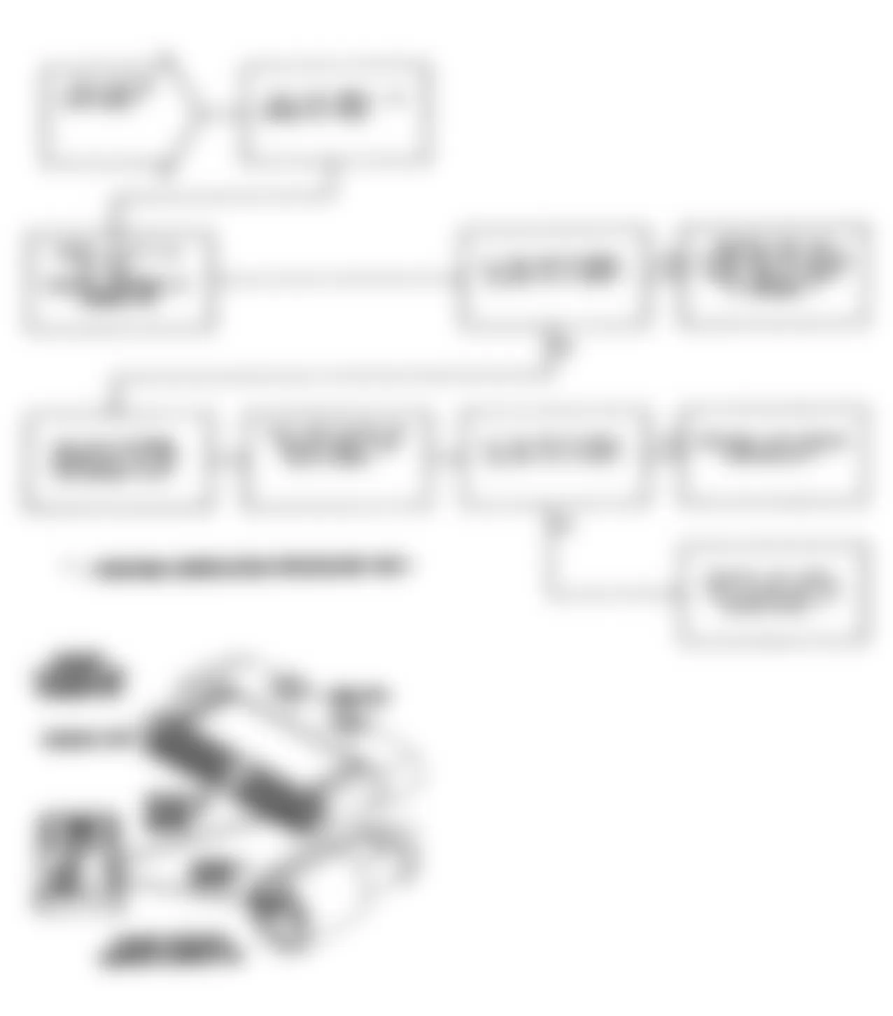
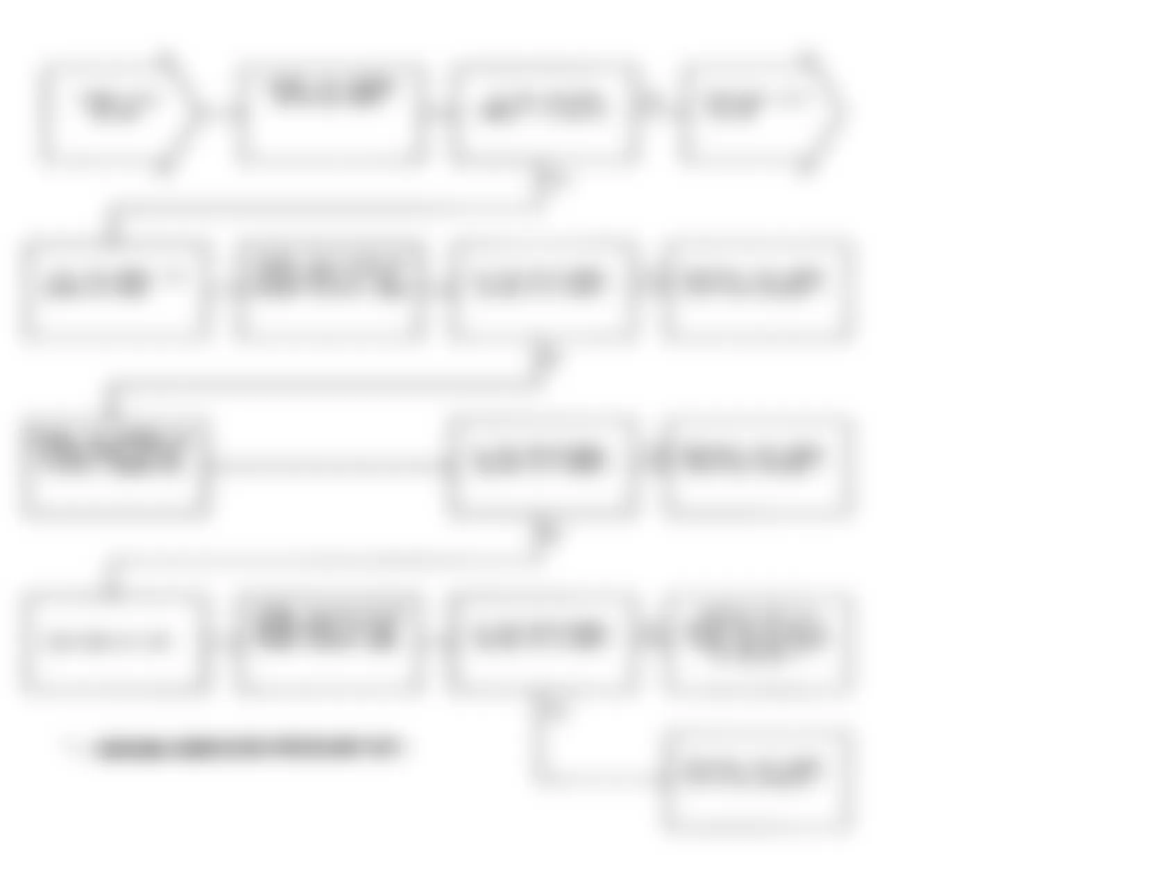
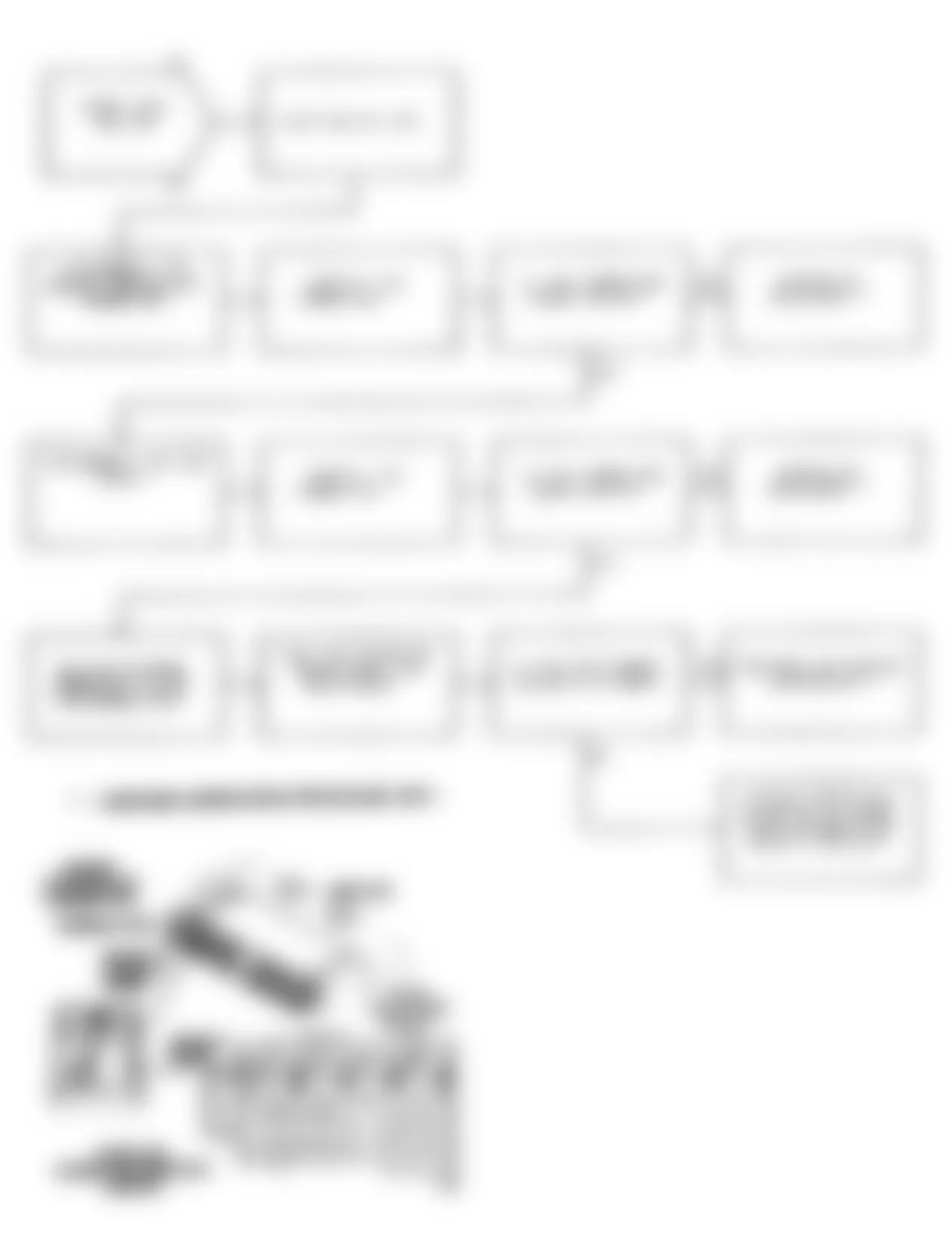
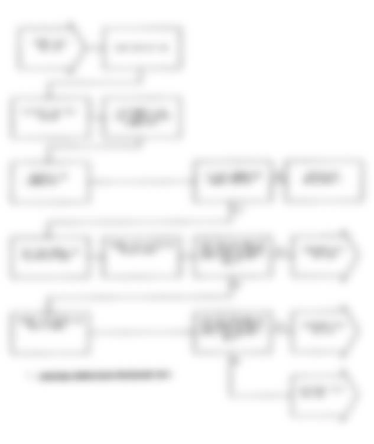
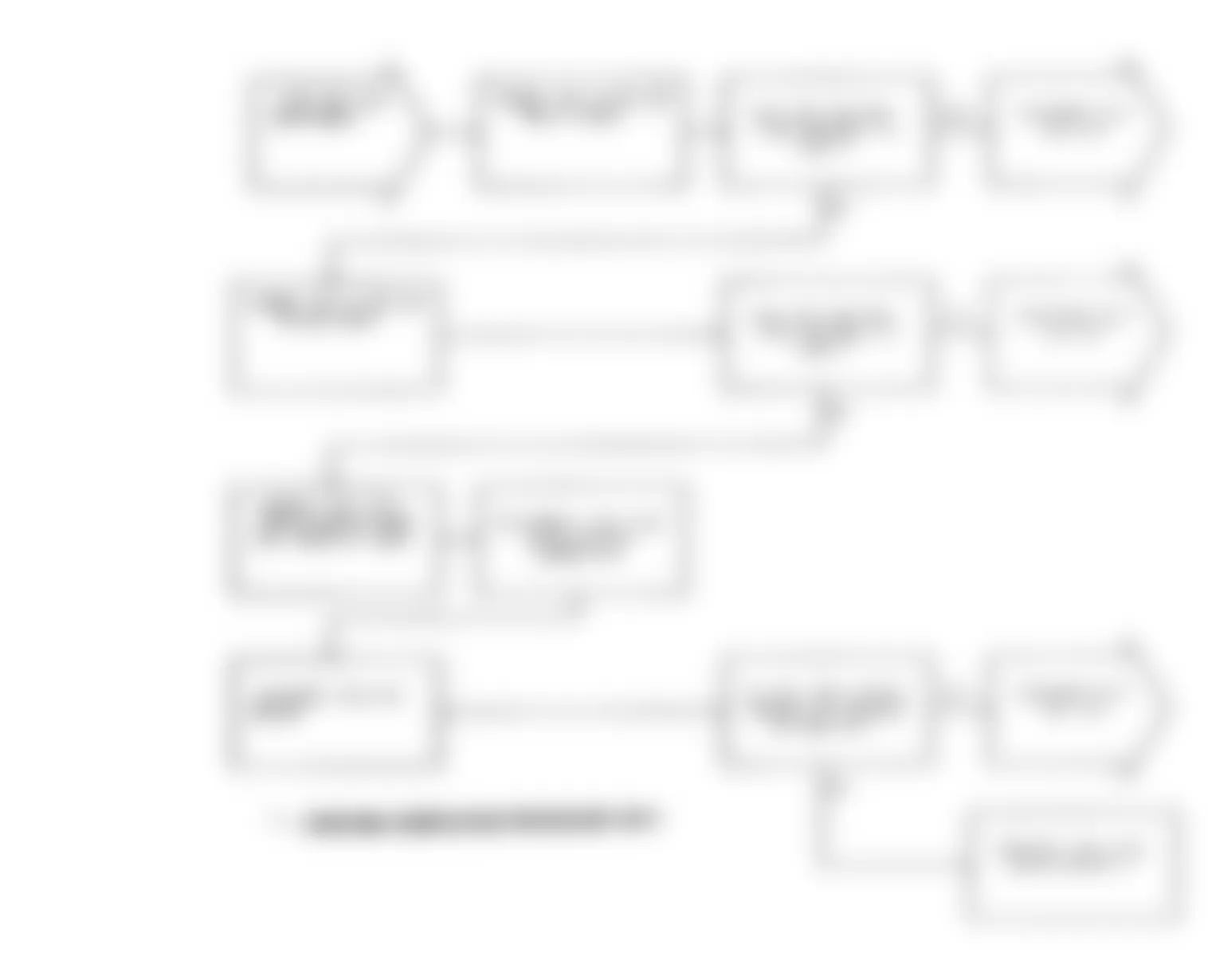
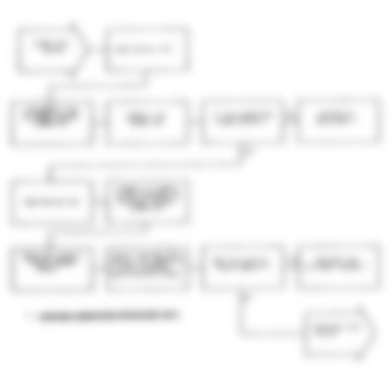
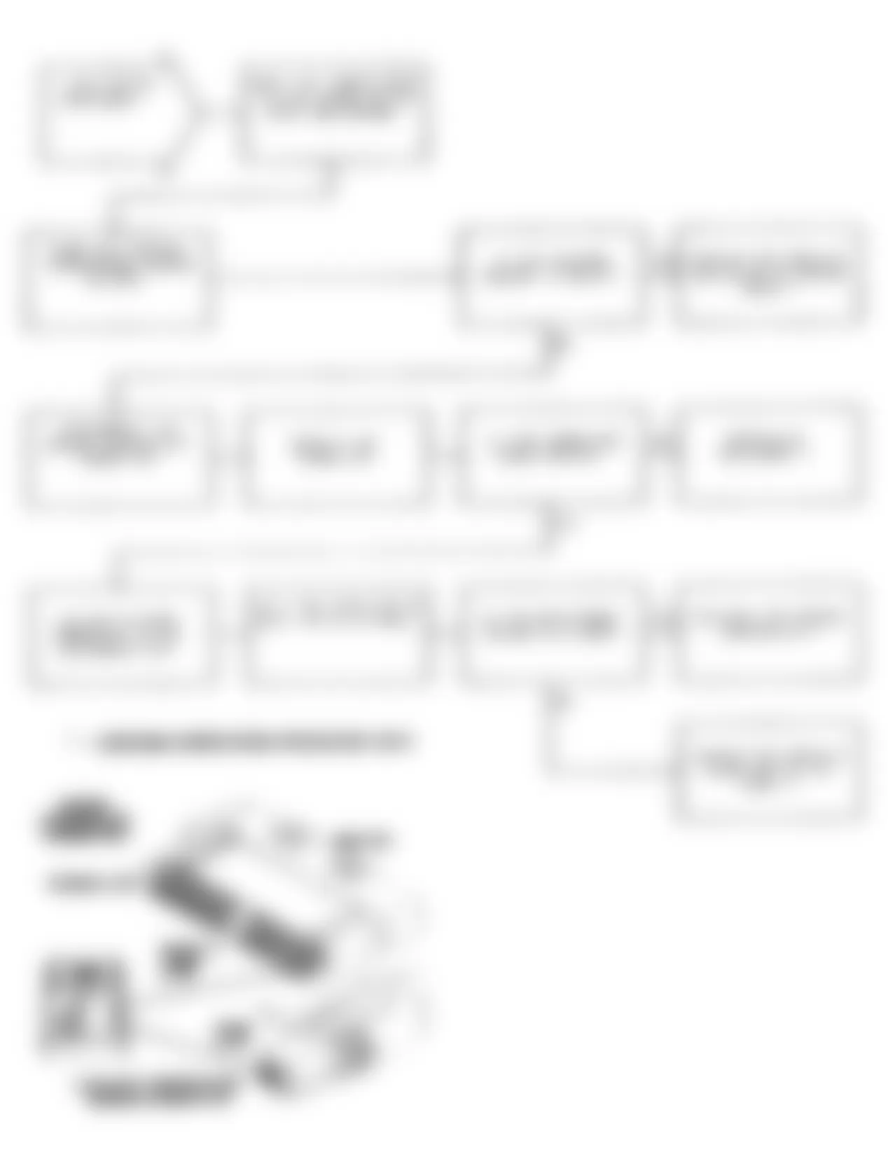
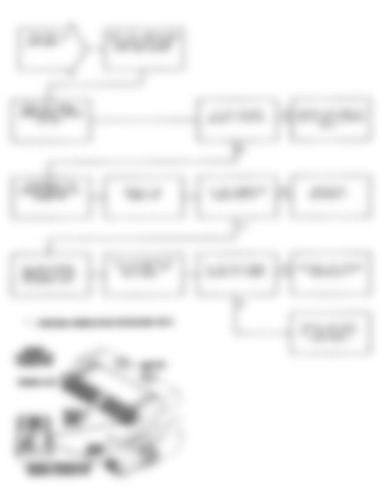
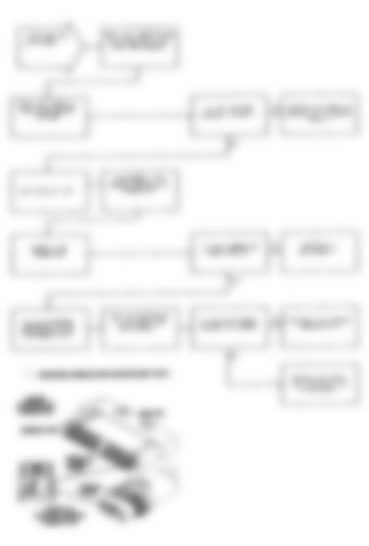
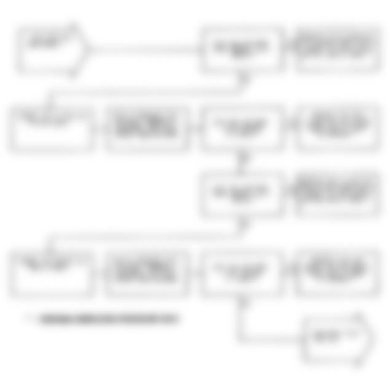
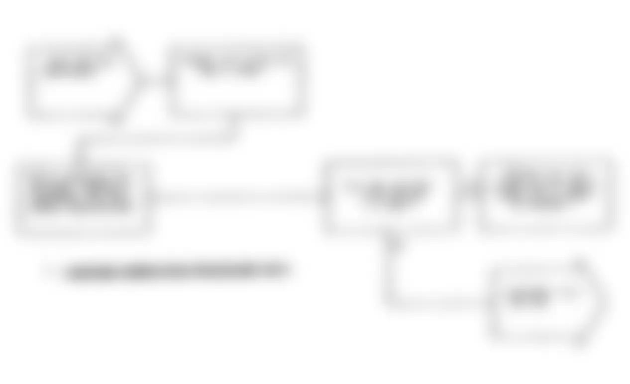
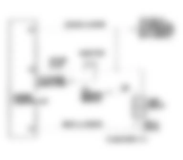
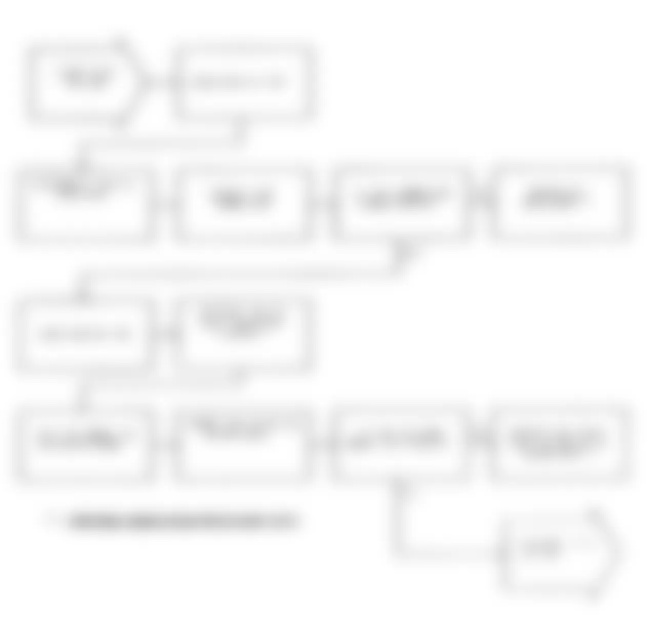
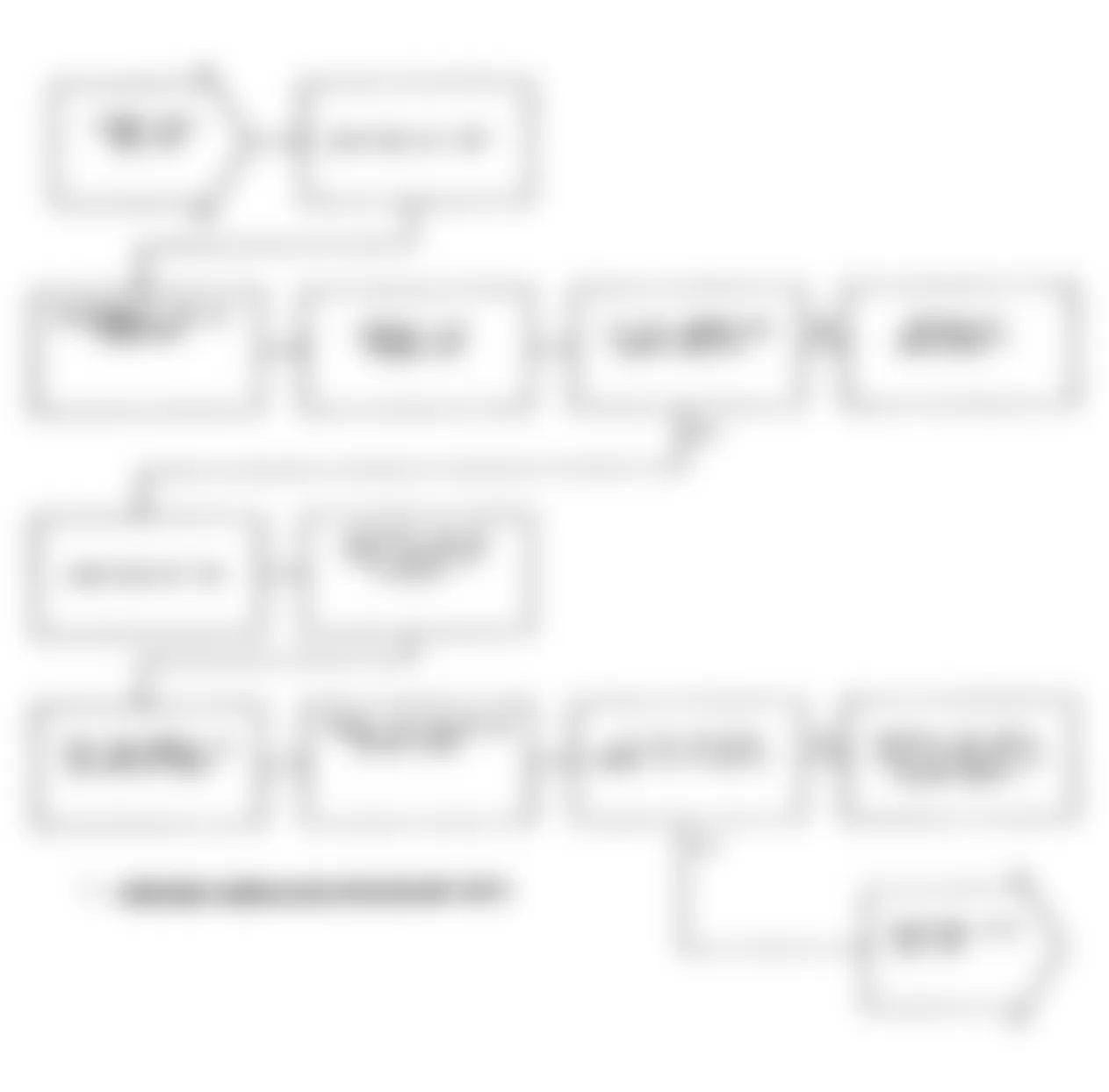
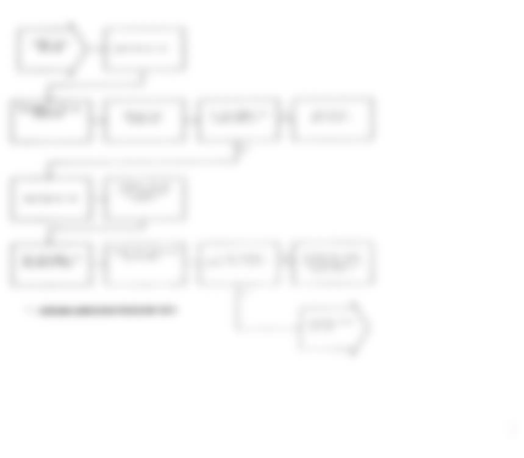
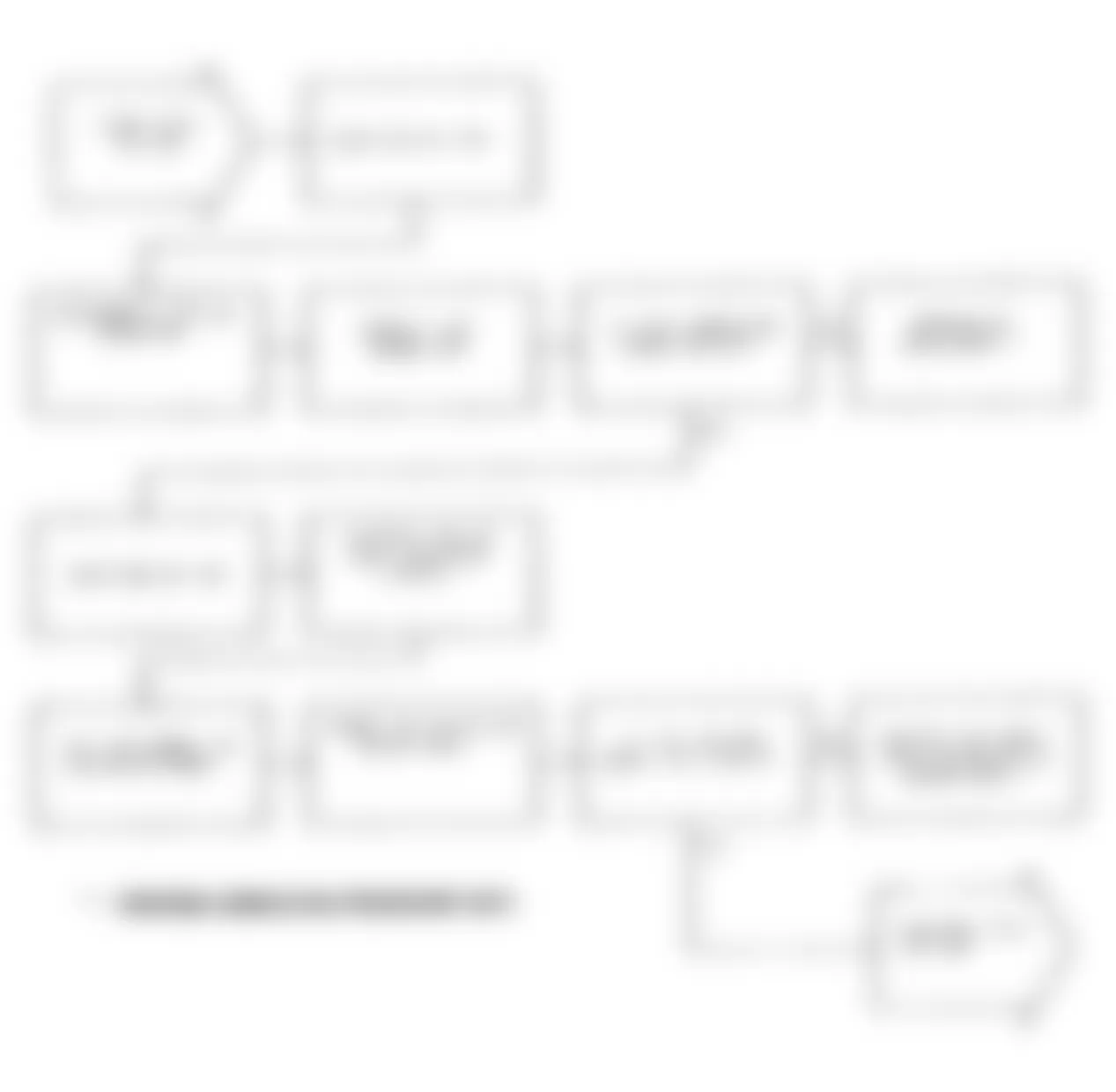
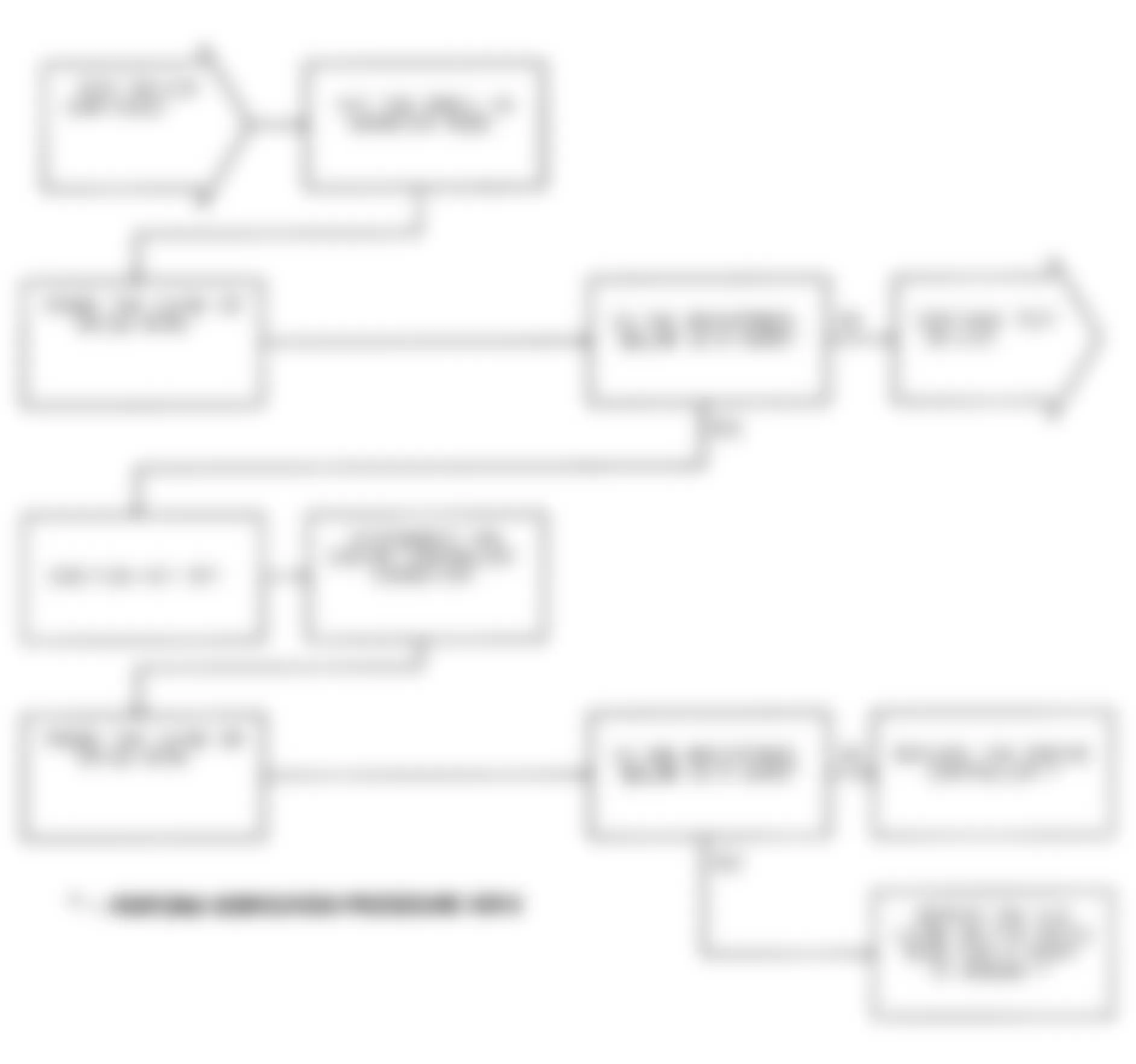
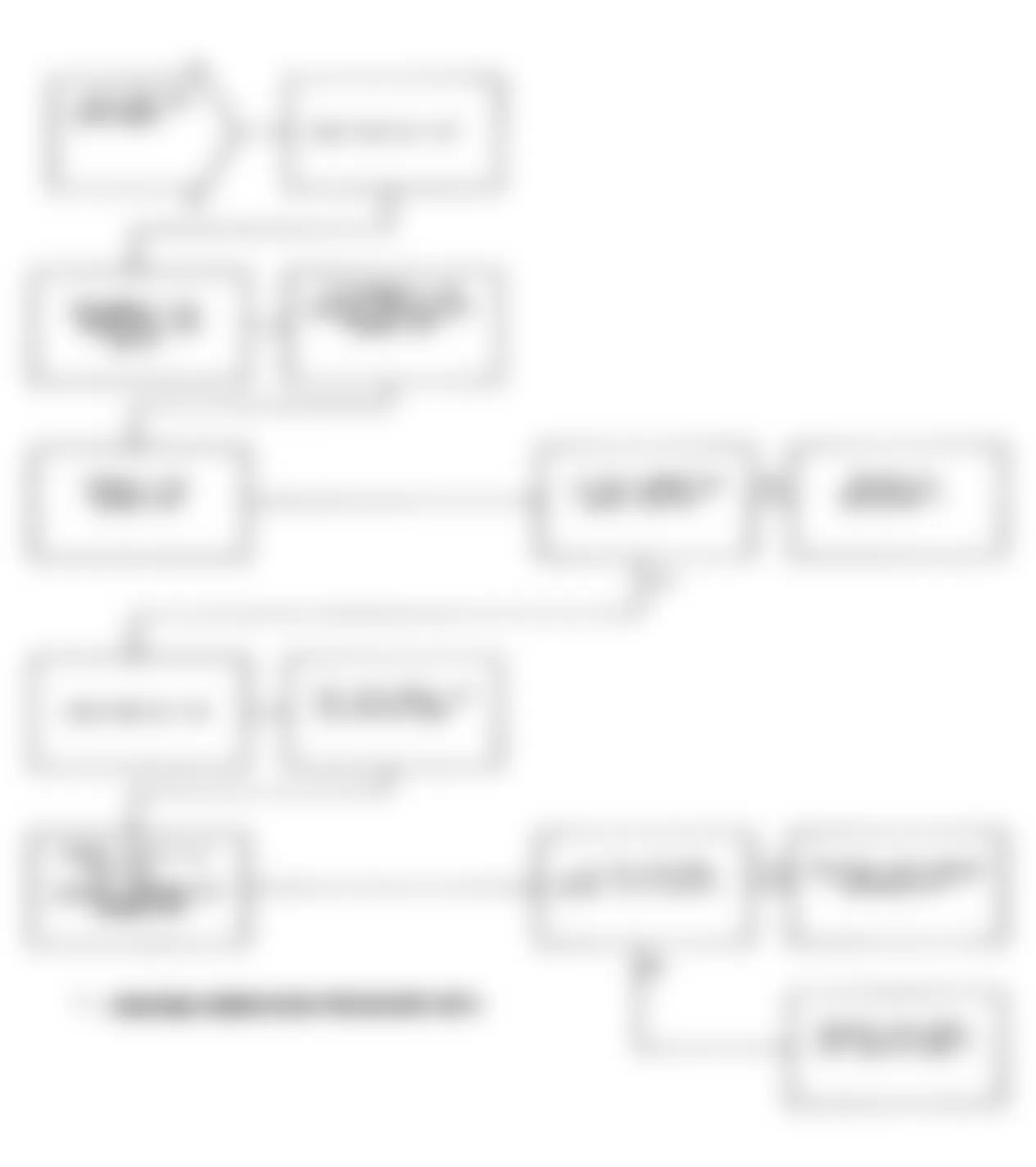
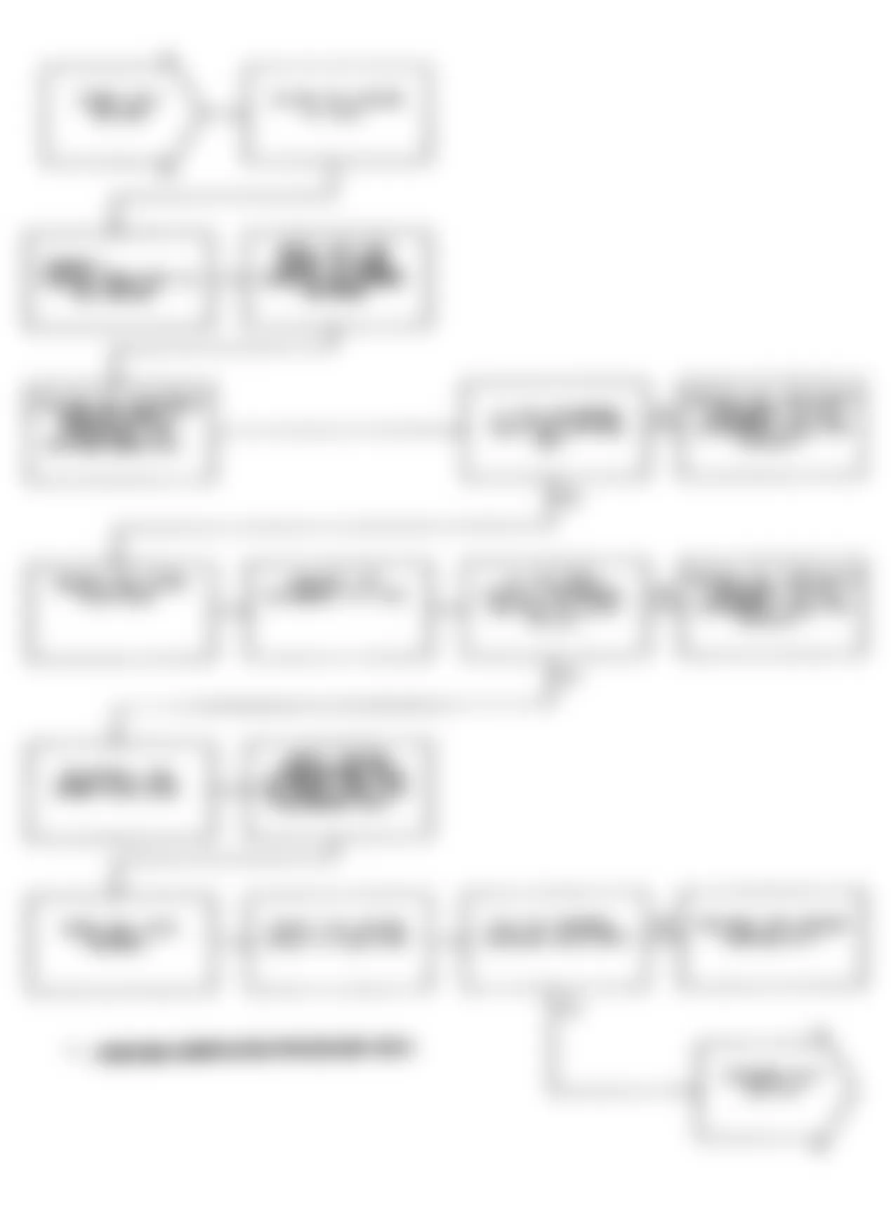
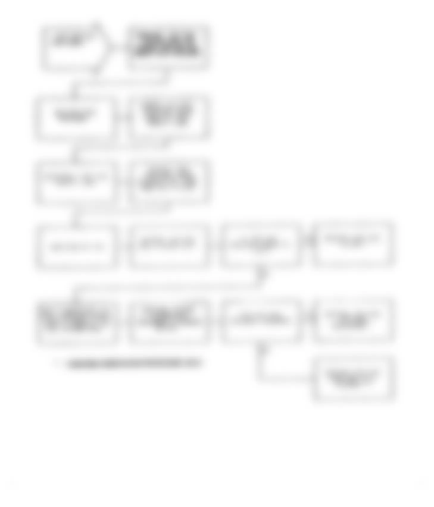
Jeep Cherokee Sport 1991 - DR-13A: REPAIRING THROTTLE POSITION SENSOR VOLTAGE HIGH
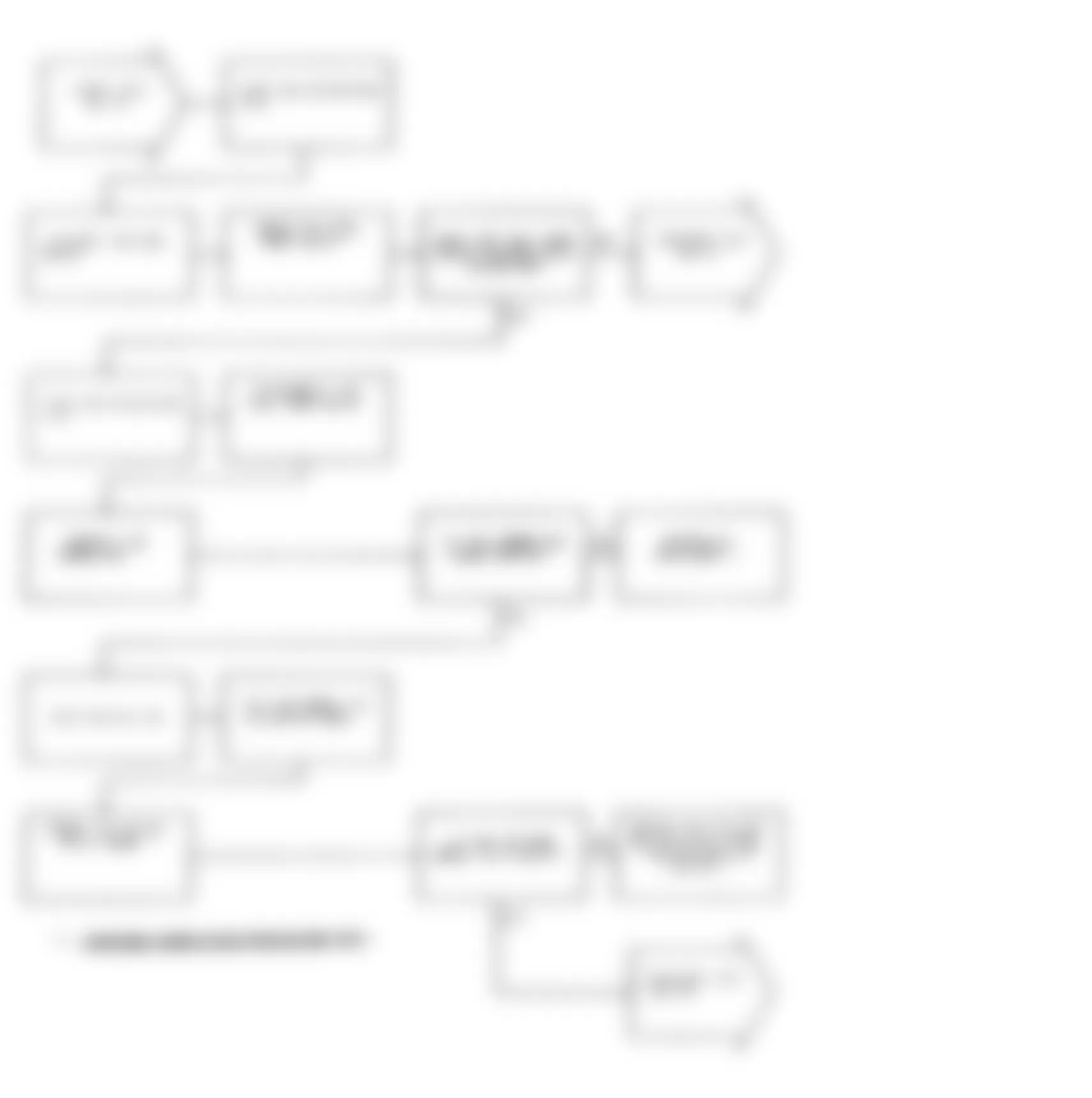
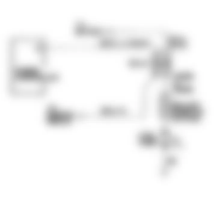
Fig. 106: Jeep Cherokee Sport 1991 - Component Locations - Test DR-13A Schematic, TPS Voltage High

Fig. 107: Jeep Cherokee Sport 1991 - Component Locations - Test DR-13A (1 of 2) TPS Voltage High
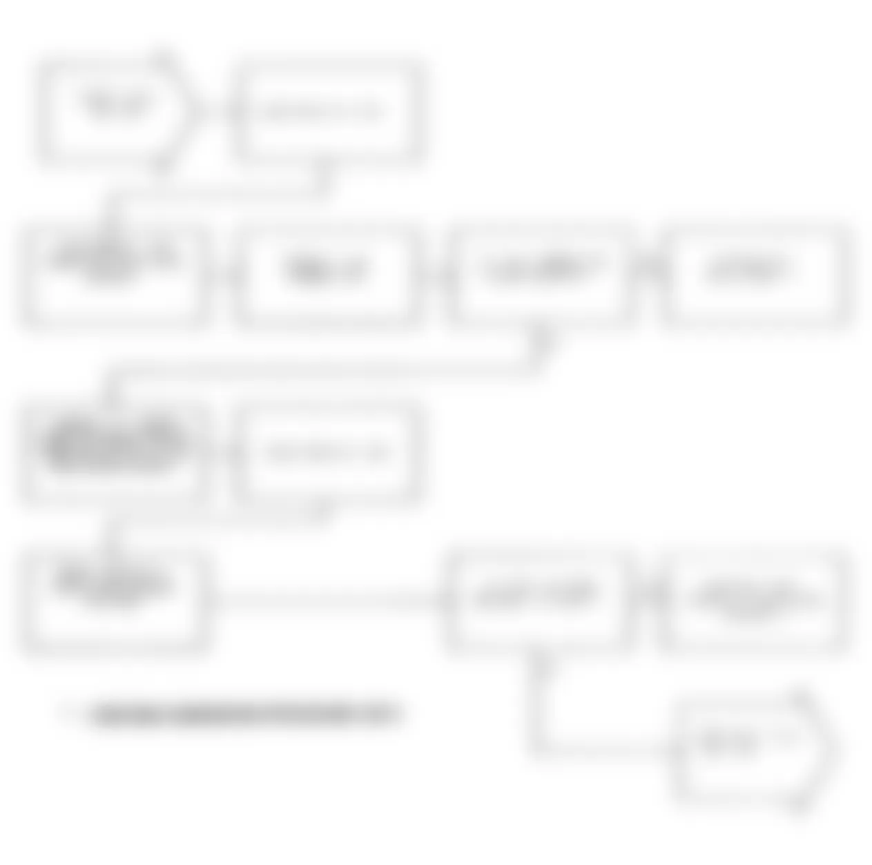
Fig. 108: Jeep Cherokee Sport 1991 - Component Locations - Test DR-13A (2 of 2) TPS Voltage High
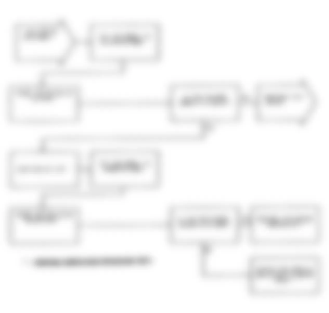
Jeep Cherokee Sport 1991 - DR-14A: REPAIRING THROTTLE POSITION SENSOR VOLTAGE LOW
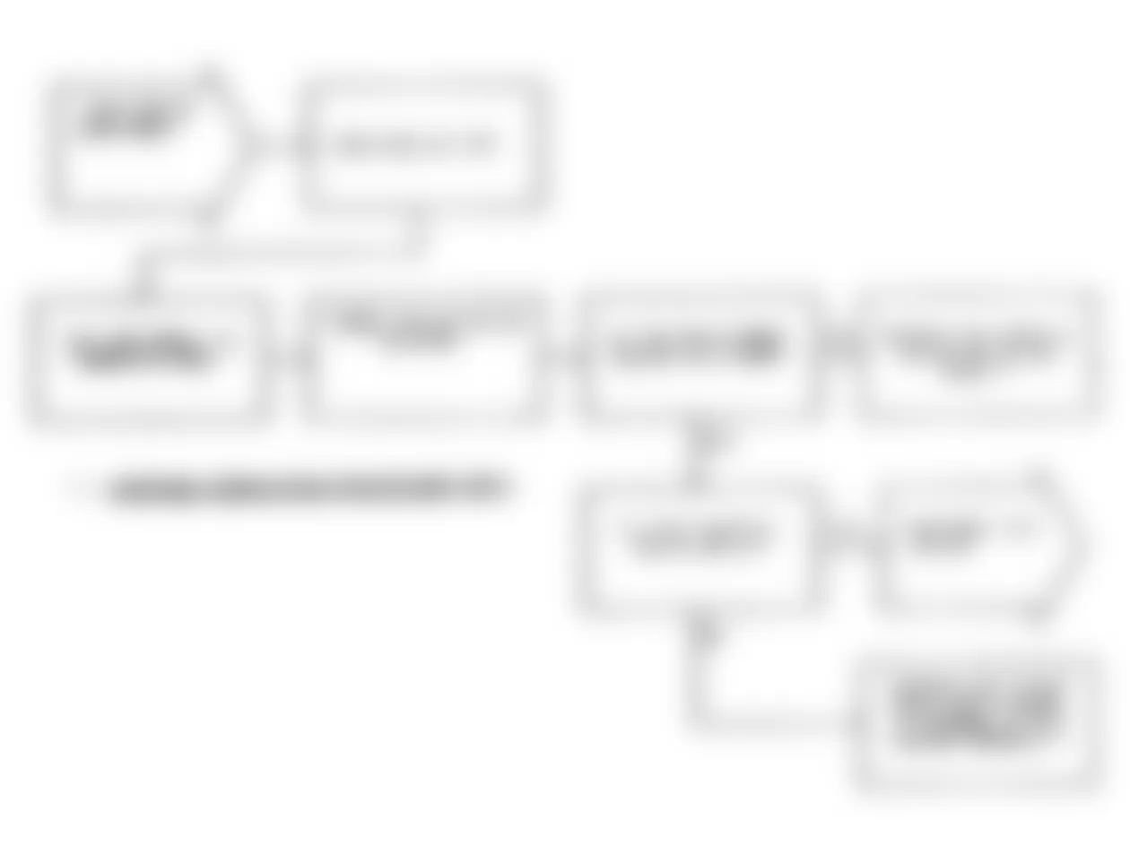
Jeep Cherokee Sport 1991 - DR-15A: REPAIRING AUTOMATIC IDLE SPEED MOTOR CIRCUITS

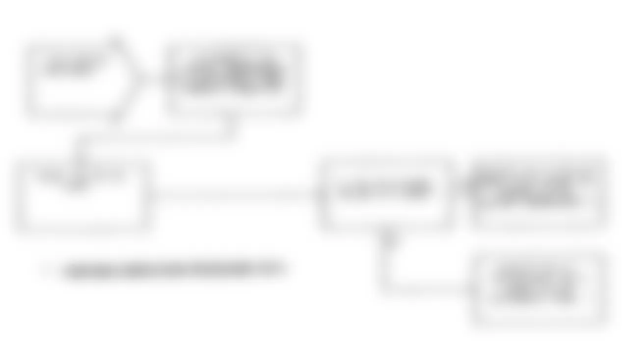
Jeep Cherokee Sport 1991 - DR-16A: REPAIRING INJECTOR #1 CONTROL CIRCUIT
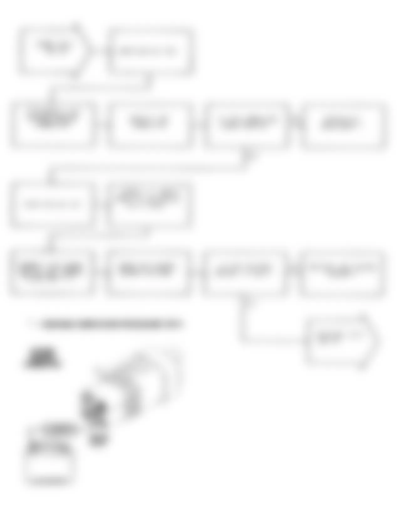
Jeep Cherokee Sport 1991 - DR-17A: REPAIRING INJECTOR #2 CONTROL CIRCUIT
Jeep Cherokee Sport 1991 - DR-18A: REPAIRING INJECTOR #3 CONTROL CIRCUIT
Jeep Cherokee Sport 1991 - DR-19A: REPAIRING INJECTOR #4 CONTROL CIRCUIT
Jeep Cherokee Sport 1991 - DR-20A: REPAIRING INJECTOR #5 CONTROL CIRCUIT
Jeep Cherokee Sport 1991 - DR-21A: REPAIRING INJECTOR #6 CONTROL CIRCUIT
Jeep Cherokee Sport 1991 - DR-22A: REPAIRING A/C CLUTCH RELAY CIRCUIT

Jeep Cherokee Sport 1991 - DR-23A: REPAIRING RADIATOR FAN RELAY CIRCUIT

Jeep Cherokee Sport 1991 - DR-24A: REPAIRING NO ASD RELAY VOLTAGE SENSE AT CONTROLLER
Jeep Cherokee Sport 1991 - DR-25A: REPAIRING CONTROLLER FAILURE EMR MILES NOT STORED OR EEPROM WRITE DENIED
Jeep Cherokee Sport 1991 - DR-26A: CHECKING SECONDARY IGNITION & TIMING
Jeep Cherokee Sport 1991 - DR-27A: CHECKING FUEL PRESSURE
Jeep Cherokee Sport 1991 - DR-27B: CHECKING FUEL PRESSURE
Jeep Cherokee Sport 1991 - DR-28A: CHECKING COOLANT & TPS CALIBRATIONS

Jeep Cherokee Sport 1991 - DR-29A: CHECKING MAP SENSOR CALIBRATION
Jeep Cherokee Sport 1991 - DR-30A: CHECKING OXYGEN SENSOR SWITCHING
Jeep Cherokee Sport 1991 - DR-30B: CHECKING OXYGEN SENSOR LOCKED LEAN

Jeep Cherokee Sport 1991 - DR-31A: CHECKING IDLE SPEED MOTOR OPERATION

Jeep Cherokee Sport 1991 - DR-31B: CHECKING IDLE SPEED MOTOR OPERATION
Jeep Cherokee Sport 1991 - DR-31C: CHECKING IDLE SPEED MOTOR OPERATION
Jeep Cherokee Sport 1991 - DR-31D: CHECKING IDLE SPEED MOTOR OPERATION
Jeep Cherokee Sport 1991 - DR-31E: CHECKING IDLE SPEED MOTOR OPERATION
Jeep Cherokee Sport 1991 - DR-32A: CHECKING PARK/NEUTRAL SWITCH INPUT
Jeep Cherokee Sport 1991 - DR-33A: CHECKING ENGINE CONTROLLER GROUNDS & POWER CIRCUITS
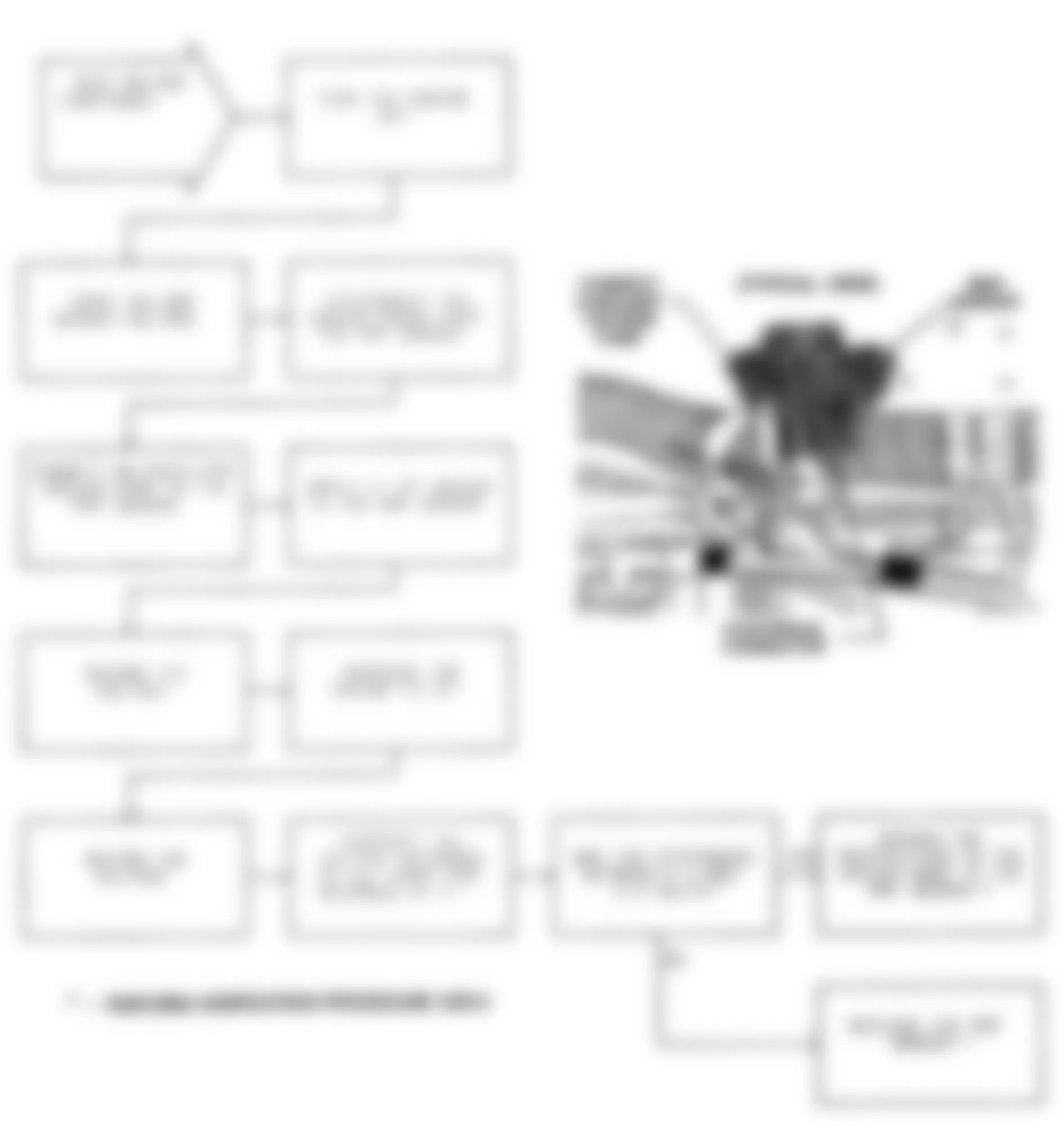
Jeep Cherokee Sport 1991 - DR-34A: PERFORMING NO FAULT CODE MECHANICAL TEST
At this point in the driveability test procedure, you have determined that all of the engine control systems are operating properly. The engine control systems are NOT the cause of the driveability problem.
The following items should be checked as possible mechanical causes of the problem:
- ENGINE VACUUM must be at least 13 in. Hg in Neutral.
- ENGINE VALVE TIMING must be within specification.
- ENGINE COMPRESSION must be within specification.
- EXHAUST SYSTEM must be free of restrictions.
- PCV SYSTEM must allow crankcase gases to flow freely.
- ENGINE CAMSHAFT & CRANKSHAFT SPROCKETS must be in good mechanical condition.
- POWER BRAKE BOOSTER must NOT have an internal vacuum leak.
- TORQUE CONVERTER STALL SPEED must be within specifications.
- FUEL CONTAMINATION: Fuel should NOT have a high alcohol or water content.
- FUEL INJECTOR(S) must NOT be plugged or restricted. Ensure that wiring harness is connected to correct injector.
NOTE: If you were directed to this test by an oxygen sensor problem, and the rich or lean condition is NOT caused by one of the items above, replace the engine controller.

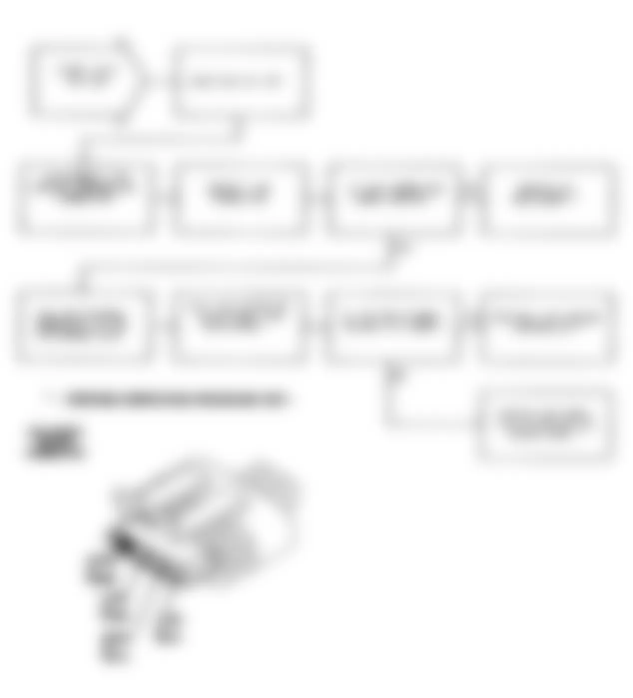
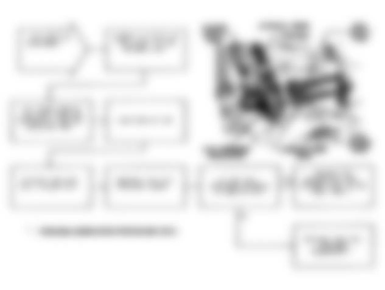
Jeep Cherokee Sport 1991 - DR-35A: INTERMITTENT TEST FOR SOLENOIDS OR RELAYS
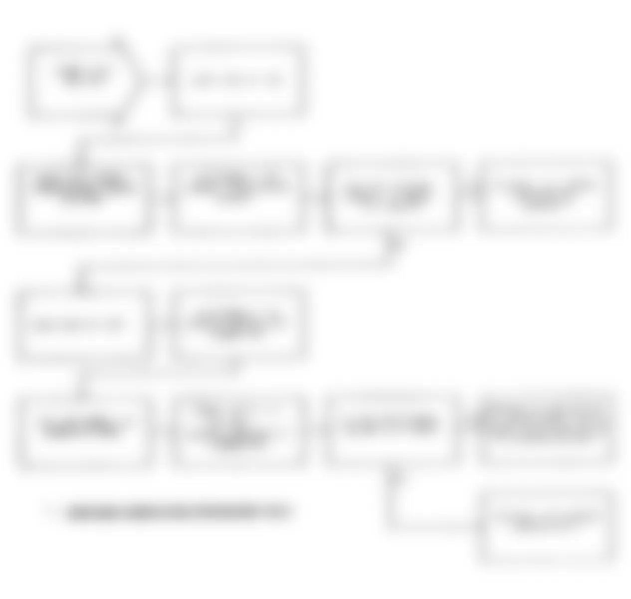
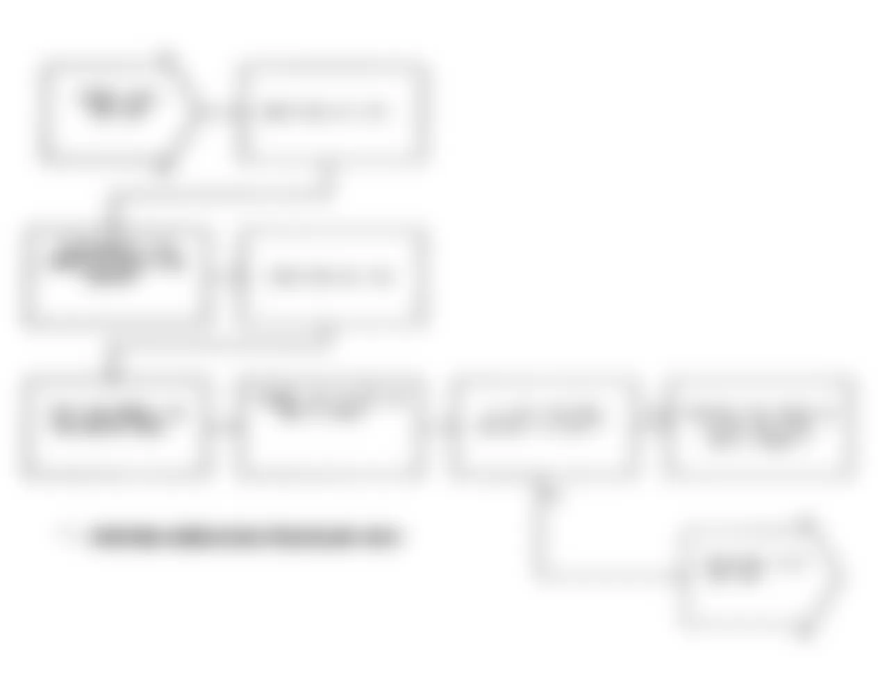
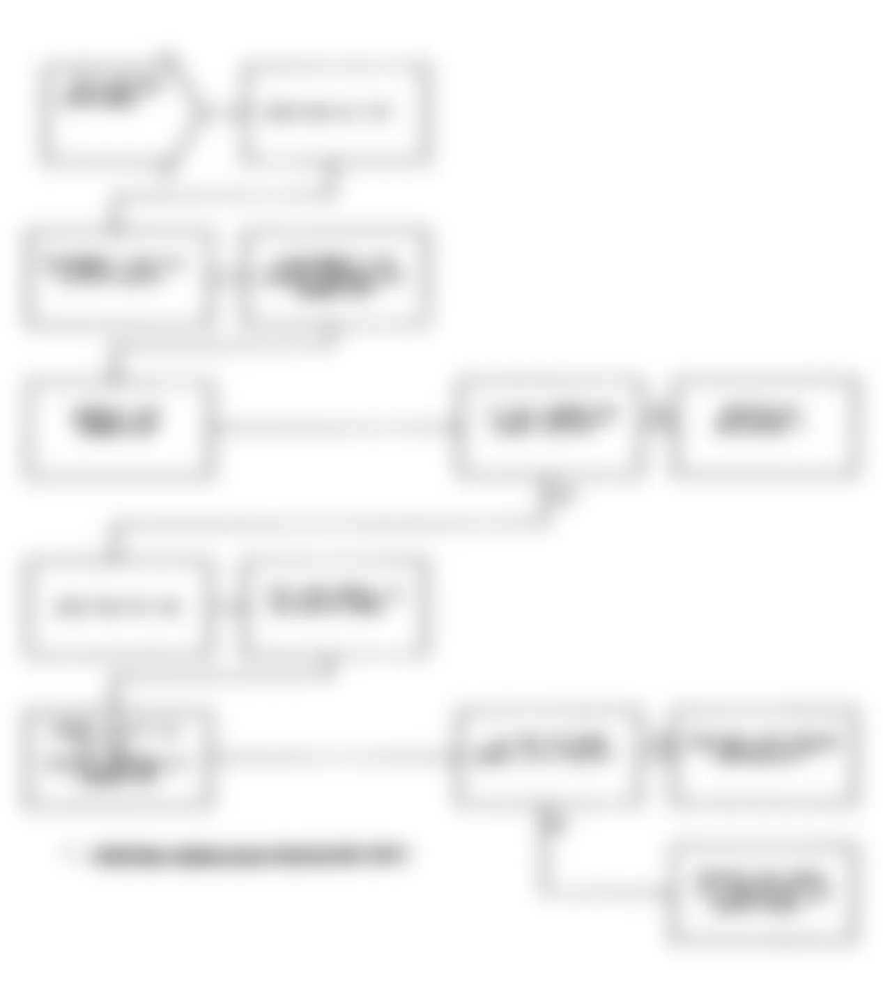
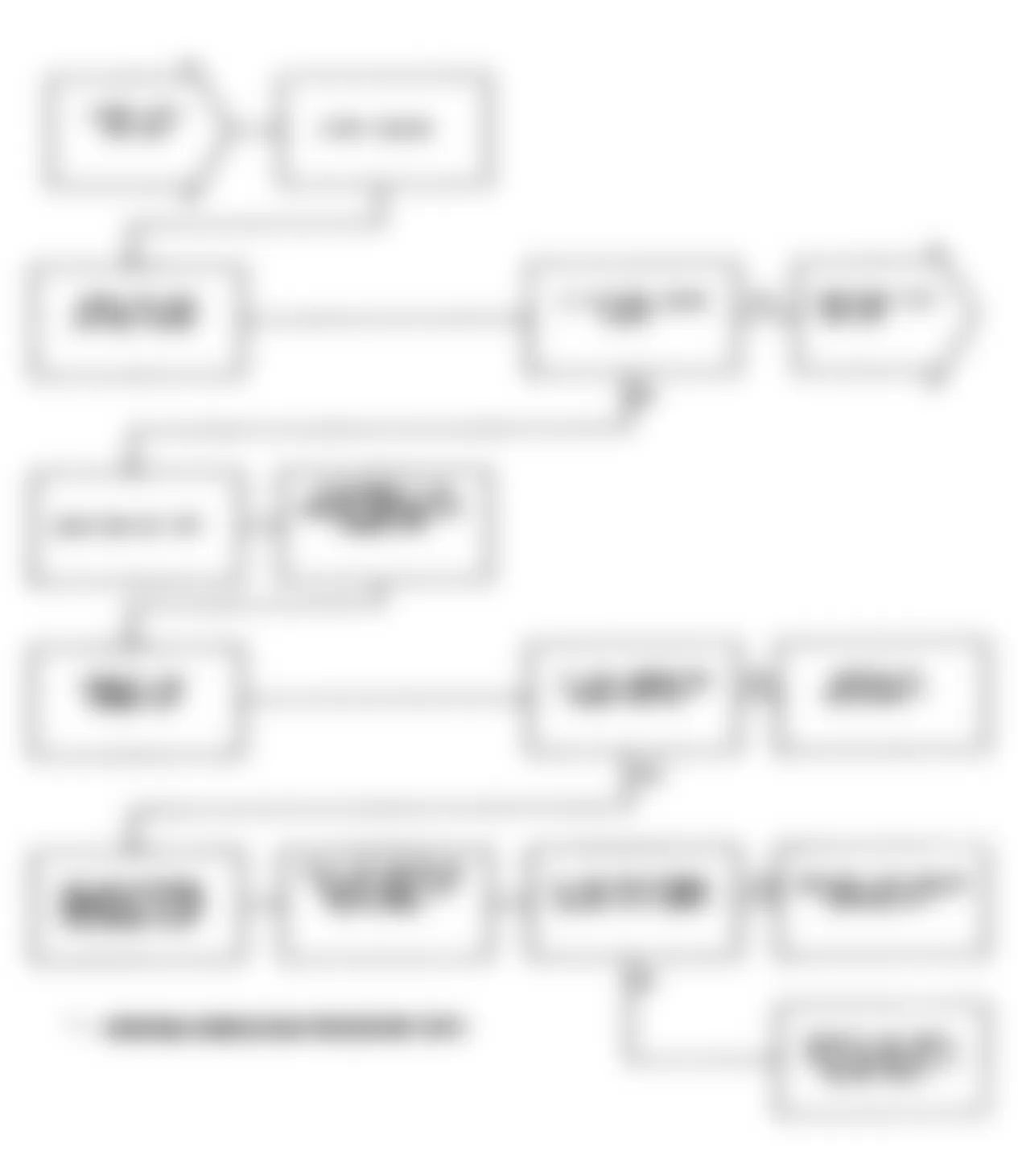
Jeep Cherokee Sport 1991 - DR-36A: INTERMITTENT TEST FOR SENSORS
Fig. 181: Jeep Cherokee Sport 1991 - Component Locations - Test DR-36A Intermittent Test For Sensors
Jeep Cherokee Sport 1991 - DR-36B: INTERMITTENT TEST FOR MAP SENSOR SIGNAL CHANGE
Jeep Cherokee Sport 1991 - DR-37A: INTERMITTENT TEST FOR AUTOMATIC IDLE SPEED MOTOR
DR-38A: INTERMITTENT TEST FOR FUEL INJECTORS
Jeep Cherokee Sport 1991 - VER-1: VERIFICATION PROCEDURE VER-1
Inspect vehicle to ensure that all components are connected. Reassemble and reconnect components as necessary. Attempt to start engine. If engine does not start, perform NO START TEST NS-1A: CHECKING FOR FAULT MESSAGES & SPARK .
If engine starts and the engine controller has been replaced, perform the following steps.
- If vehicle is equipped with a factory theft alarm system, start vehicle at least 20 TIMES so that the theft alarm system may be activated when desired.
- Write (transfer) EMR mileage into new engine controller. See EMISSION MAINTENANCE REMINDER (EMR) MILEAGE TRANSFER .
- The no start condition has been corrected. The repair procedure is now complete. If engine starts and the engine controller has NOT been replaced, perform the following steps:
- Connect DRB-II to engine diagnostic connector and erase faults.
- The no start condition has been corrected and the fault messages have been erased. The repair procedure is now complete.
Jeep Cherokee Sport 1991 - VER-2: VERIFICATION PROCEDURE VER-2
NOTE: If VERIFICATION PROCEDURE VER-3 was performed previously, perform VERIFICATION PROCEDURE VER-3 once again.
Inspect vehicle to ensure that all components are connected. Reassemble and reconnect components as necessary. If there is another fault that has not been dealt with, return to DRIVEABILITY TEST DR-1A: CHECKING SYSTEM FOR FAULTS and perform the specified procedure for that fault.
If engine controller has been changed, perform the following steps:
- If vehicle is equipped with a factory theft alarm system, start vehicle at least 20 TIMES so that the theft alarm system may be activated when desired.
- Write (transfer) EMR mileage into new engine controller. See EMISSION MAINTENANCE REMINDER (EMR) MILEAGE TRANSFER .
- Connect DRB-II to engine diagnostic connector and erase faults. To ensure that no other faults remain, perform the following steps:
- Start engine and allow it to reach normal operating temperature. Manually run engine at 2000 RPM of at least 10 seconds and allow engine to return to idle.
- If vehicle is equipped with an automatic transmission, step on brake pedal and shift through all gears. Return shift lever to PARK position. If vehicle is equipped with air conditioning, place A/C-heater blower fan on low speed and turn A/C system on.
- Turn ignition off. Restart engine and allow it to idle for at least 2 MINUTES. Turn ignition off. Connect DRB-II to engine diagnostic connector and check for faults. If there are no faults, the repair is now complete.
- If the repaired fault has reset, the repair procedure is incomplete. Check for technical service bulletins that relate to this driveability problem and return to DRIVEABILITY TEST DR-1A: CHECKING SYSTEM FOR FAULTS if necessary.
- If there is another fault that has not been dealt with, return to DRIVEABILITY TEST DR-1A: CHECKING SYSTEM FOR FAULTS and perform the specified procedure for that fault.
Jeep Cherokee Sport 1991 - VER-3: VERIFICATION PROCEDURE VER-3
Inspect vehicle to ensure that all components are connected. Reassemble and reconnect components as necessary. If there is another fault that has not been dealt with, return to DRIVEABILITY TEST DR-1A: CHECKING SYSTEM FOR FAULTS and perform the specified procedure for that fault.
If engine controller has been changed, perform the following steps:
- If vehicle is equipped with a factory theft alarm system, start vehicle at least 20 TIMES so that the theft alarm system may be activated when desired.
- Write (transfer) EMR mileage into new engine controller. See EMISSION MAINTENANCE REMINDER (EMR) MILEAGE TRANSFER .
- Connect DRB-II to engine diagnostic connector and erase faults. Disconnect DRB-II from vehicle. To ensure that no other faults remain, perform the following steps:
- If vehicle is equipped with air conditioning, place A/C-heater blower fan on low speed and turn A/C system on. Road test vehicle for at least 5 MINUTES and at some point attain a speed of at least 40 MPH, ensuring that transmission shifts through all gears. Upon completion of road test, turn ignition off.
- Restart engine and allow it to idle for at least 2 MINUTES. Turn ignition off. Connect DRB-II to engine diagnostic connector and check for faults. If there are no faults, the repair is now complete.
- If the repaired fault has reset, the repair procedure is incomplete. Check for technical service bulletins that relate to this driveability problem and return to DRIVEABILITY TEST DR-1A: CHECKING SYSTEM FOR FAULTS if necessary.
- If there is another fault that has not been dealt with, return to DRIVEABILITY TEST DR-1A: CHECKING SYSTEM FOR FAULTS and perform the specified procedure for that fault.