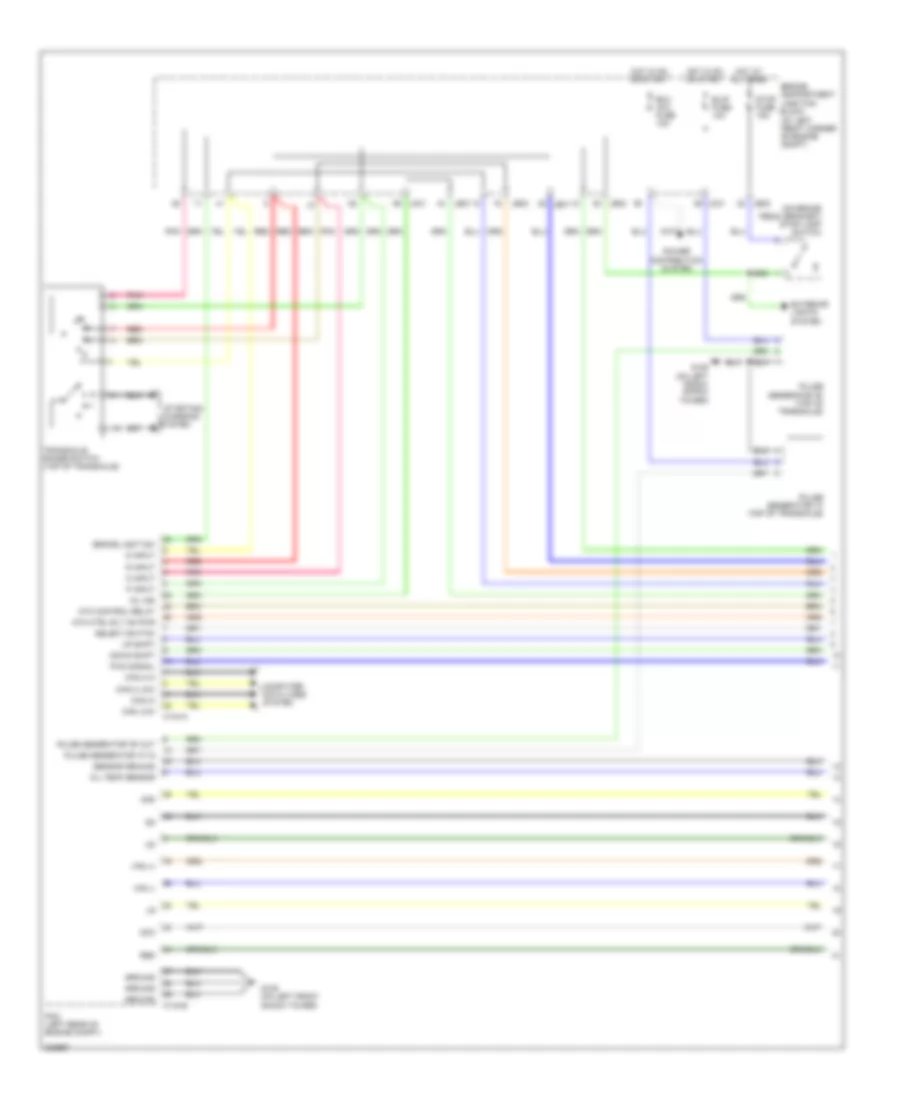
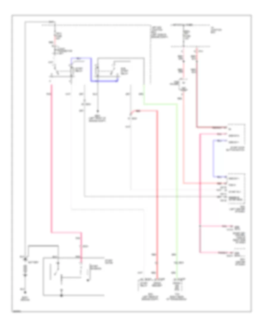
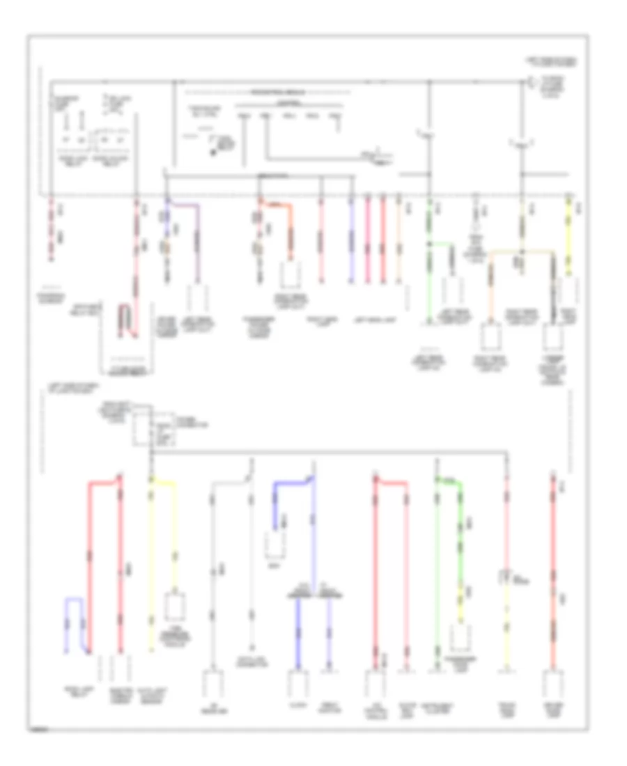
RADIO
Radio Wiring Diagram, with Navigation & with AV Amplifier (1 of 2) for Hyundai Azera GLS 2011
 https://portal-diagnostov.com/license.html
Automotive Electricians Portal FZCO
Automotive Electricians Portal FZCO
https://portal-diagnostov.com/license.html
https://portal-diagnostov.com/license.html
Automotive Electricians Portal FZCO
Automotive Electricians Portal FZCO
List of elements for Radio Wiring Diagram, with Navigation & with AV Amplifier (1 of 2) for Hyundai Azera GLS 2011:
- (+)
- (-)
- (under center console)
- 12v sw1
- Acc/on in
- Alt l
- Aud in com
- Aud in l
- Aud in r
- Aud out com
- Aud out l
- Aud out r
- Audio
- Clock spring
- Eq sel
- F54-b
- F54-d
- Fbatt
- Fd11
- Fd12
- Ff21
- Fl (+)
- Fl (-)
- Fr (+)
- Fr (-)
- Gf01
- Gnd
- Hot at all times
- I/p junction box
- I/p-f
- Ill
- Ill (+)
- Ill (-)
- Interior lights system
- Lcd dim
- Led dim
- Left audio remocon switch
- Left front tweeter speaker
- M02-r
- M80-b
- M80-c1
- Memory power
- Mf81
- Mf91
- Mode
- Multifunction switch
- Mute
- Nca
- Pgnd
- Pnk
- Power
- R sw1
- R sw2
- Red
- Right front tweeter speaker
- Rl (+)
- Rl (-)
- Rr (+)
- Rr (-)
- Rse det
- Rse module (under front passenger's seat)
- Rse/ smart key fuse 10a
- Seek down
- Seek up
- Starting/charging system
- Steering wheel
- Sub woofer speaker
- Trim plate module
- Vol down
- Vol up
- W/ audio remocon
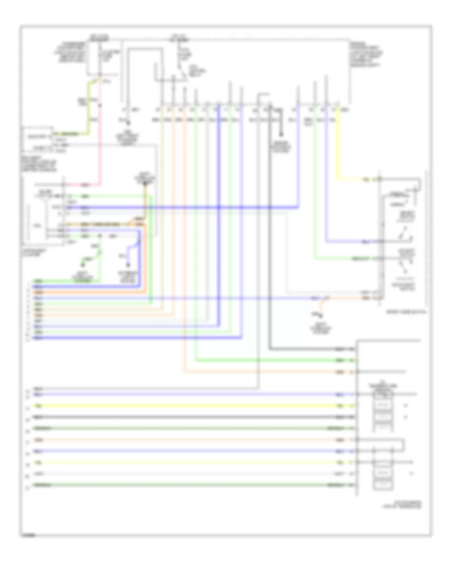
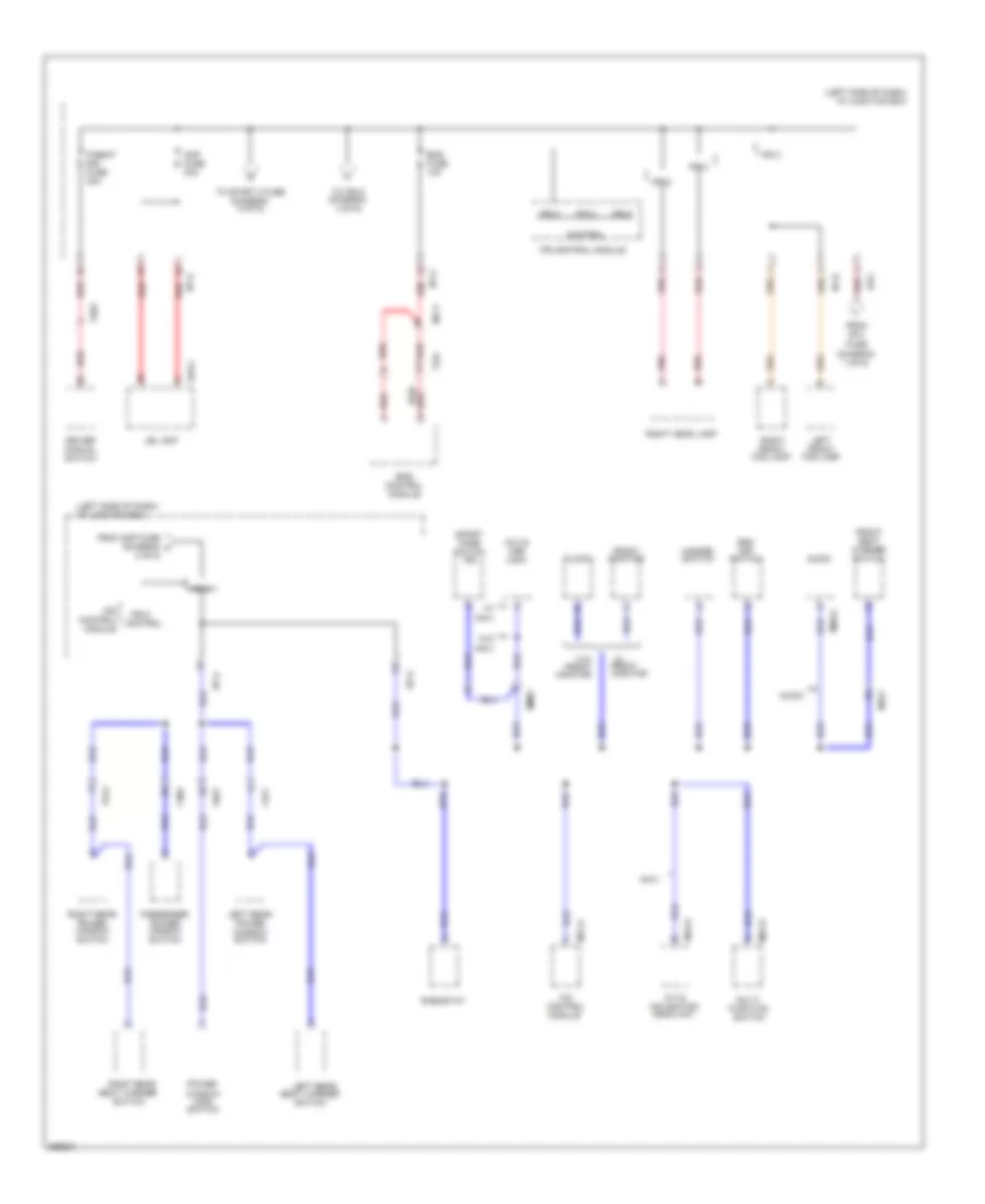
Radio Wiring Diagram, with Navigation & with AV Amplifier (2 of 2) for Hyundai Azera GLS 2011
List of elements for Radio Wiring Diagram, with Navigation & with AV Amplifier (2 of 2) for Hyundai Azera GLS 2011:
- (at left front corner of engine compt)
- (on brake pedal bracket) stop lamp switch
- 2nd
- Atm control relay
- Atm ctrl rly on pwr
- B/up fuse 10a
- Brake light sw
- C144-a
- C144-b
- Can 2 hi
- Can 2 low
- Can hi
- Can low
- Computer data lines system
- D input
- Dcc
- Down shift
- Ecu (ig1) fuse 10a
- Engine compartment junction block
- Exterior lights system
- G109 (on left front shock tower)
- Ground
- Hot at all times
- Hot in on or start
- Jc01
- Je01
- Je02
- Mil ind
- N input
- Oil temp sensor
- P input
- Pcm (left rear of engine compt)
- Pnk
- Power distribution system
- Pulse generator "a" (top of transaxle)
- Pulse generator "a" in
- Pulse generator "b" (top of transaxle)
- Pulse generator "b" out
- Pwm signal
- R input
- Red
- Select switch
- Sensor ground
- Starting/ charging
- Stop fuse 15a
- System
- Transaxle range switch (top of transaxle)
- Up shift
- Vfs (+)
- Vfs (-)
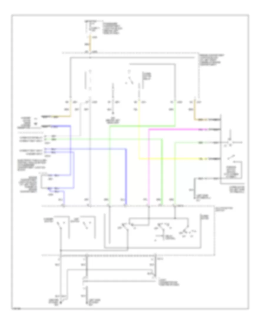
Radio Wiring Diagram, with Navigation & with JBL Amplifier (1 of 2) for Hyundai Azera GLS 2011
List of elements for Radio Wiring Diagram, with Navigation & with JBL Amplifier (1 of 2) for Hyundai Azera GLS 2011:
- Atm control relay
- Atm fuse 20a
- Atm solenoid (top of transaxle)
- Bcm (body control module) (under front of center console)
- Cluster fuse 10a
- Down shift switch
- Engine compartment junction block (at left front corner of engine compt)
- Engine controls system
- Exterior lights system
- G06 (left front of engine compt)
- Hot at all times
- Hot in on or start
- I/p-a
- Inhibit 'p'
- Instrument cluster
- Jc01
- Je01
- Je02
- M08-1
- M08-3
- M33-a
- M33-c
- Manual
- Mcu
- Mil ind
- Normal
- Oil temperature sensor
- On/start in
- Passenger compartment junction block (behind left side of dash)
- Pnk
- Pwm
- Select switch
- Shift interlock system
- Sport mode switch
- Up shift switch
Radio Wiring Diagram, with Navigation & with JBL Amplifier (2 of 2) for Hyundai Azera GLS 2011
List of elements for Radio Wiring Diagram, with Navigation & with JBL Amplifier (2 of 2) for Hyundai Azera GLS 2011:
- (center of dash) g04
- (left side of dash) g03
- (left side of firewall) g11
- A12
- Delay control
- Electronic time & alarm control module (etacm) (in passenger compartment junction block)
- Engine compartment junction block (at left front corner of engine compartment)
- F12
- Fuse 11 15a
- G02 (behind left headlamp)
- Hot at on
- Int
- Intermittent input
- Jc01
- Je01
- Jm05
- Jm09
- Joint connector m08 (center of dash)
- M01-2
- M33-1
- M33-2
- Mist switch
- Multifunction switch
- Nca
- Off
- Parking switch (shown with wipers at rest)
- Passenger compartment junction block (behind left side of dash)
- Washer input
- Washer motor (near washer reservoir)
- Washer switch
- Wiper motor
- Wiper motor (on left side of firewall)
- Wiper motor relay
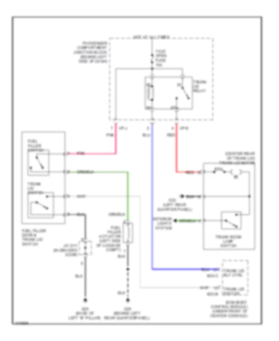
Radio Wiring Diagram, without Navigation & JBL Amplifier for Hyundai Azera GLS 2011
List of elements for Radio Wiring Diagram, without Navigation & JBL Amplifier for Hyundai Azera GLS 2011:
- (center rear of trunk lid) trunk lid motor
- (left rear quarter panel)
- Bcm (body control module) (under front of center console)
- Fuel filler actuator (left side of luggage compt)
- Fuel filler door & trunk lid switch
- Fuel filler switch
- G25 (base of left "b" pillar)
- G26 (behind left rear quarterpanel)
- G32
- Hot at all times
- I/p-e
- I/p-j
- Interior lights system
- J/c d11 (in driver's door)
- M33-b
- M33-c
- Passenger compartment junction block (behind left side of dash)
- Pnk
- Ptc
- Red
- T/lid open fuse 15a
- Trunk lid relay
- Trunk lid rly ctrl
- Trunk lid switch
- Trunk room lamp switch
Radio Wiring Diagram, without Navigation & with AV Amplifier (1 of 2) for Hyundai Azera GLS 2011
List of elements for Radio Wiring Diagram, without Navigation & with AV Amplifier (1 of 2) for Hyundai Azera GLS 2011:
- (left rear of engine compt)
- (right rear of transmission)
- Battery
- Bcm (center of dash)
- Body ground
- Clg-b
- Clg-zf
- Crank request
- Crank- ing sig (p/n)
- Ec21
- Ecm
- Elg-a
- Em21
- Escl sw fuse 10a
- Fob holder
- Fob in
- Ge03 (left front of engine compt)
- Hot at all times
- I/p junction box
- I/p-a
- Ign 2 fuse 40a
- Joint connector je71
- Key in sw
- Left e/r junction box (left side of engine compt)
- M51-a
- M51-b
- Pdm (left center of dash)
- Pnk
- Red
- Reserve (start-ems) m51-b
- Smart key control module (right side of dash)
- Ssb sw-1
- Ssb sw-2
- Ssb sw-2 m02-a
- Ssb sw-2 m14-a
- Start motor
- Start relay
- Start rly
- Start solenoid
- Start stop button switch
- Sub start relay
- Tcm
Radio Wiring Diagram, without Navigation & with AV Amplifier (2 of 2) for Hyundai Azera GLS 2011
List of elements for Radio Wiring Diagram, without Navigation & with AV Amplifier (2 of 2) for Hyundai Azera GLS 2011:
- (center of
- (left front of engine compt)
- (left rear of engine
- (left rear of engine compt)
- Acc
- B/ alarm ctrl
- B/alarm
- Battery
- Bcm
- Body ground
- Clg-b
- Clg-zf
- Compt)
- Crank request
- Crank- ing sig (p/n)
- Dash)
- Ec21
- Ecm
- Elg-a
- Em11
- Em21
- Ge03
- I/p junction box
- I/p-a
- Icm relay box (left side of dash)
- Ign 1 fuse 30a
- Ign 2 fuse 40a
- Ignition switch
- J/c je71
- Left e/r junction box (left side of engine compt)
- Lock
- M02-c
- M13-b
- Pnk
- Red
- Relay
- Start
- Start fuse 10a
- Start motor
- Start relay
- Start solenoid
- Sub start relay
- Tcm
- W/ immobilizer
- W/o immobilizer
Radio Wiring Diagram, without Navigation & with JBL Amplifier (1 of 2) for Hyundai Azera GLS 2011
List of elements for Radio Wiring Diagram, without Navigation & with JBL Amplifier (1 of 2) for Hyundai Azera GLS 2011:
- (center of dash)
- (left center of dash)
- (left rear of engine compt)
- (left side of engine compt)
- 2.0l
- 3.8l
- All times
- Battery
- Bcm
- Body ground
- Ec21
- Ecm
- Elg-a
- Em21
- Em51
- Escl sw fuse 10a
- Fob holder
- Fob in
- Ge04
- Ge05 (left front of engine compt)
- Hot at
- I/p junction box
- I/p-a
- Ign 2 fuse 40a
- Ignition lock switch (left toe board)
- J/c je71
- Key in sw
- Left e/r junction box (left side of engine compt)
- M02-a
- M14-a
- M51-a
- M51-b
- Nca
- Pdm
- Pnk
- Pnk/
- Red
- Red/
- Reserve
- Rly
- Smart key control module (right side of dash)
- Ssb sw-1
- Ssb sw-2
- Start
- Start motor
- Start relay
- Start solenoid
- Start stop button switch
Radio Wiring Diagram, without Navigation & with JBL Amplifier (2 of 2) for Hyundai Azera GLS 2011
List of elements for Radio Wiring Diagram, without Navigation & with JBL Amplifier (2 of 2) for Hyundai Azera GLS 2011:
- 1st
- 2nd
- A05-a
- A17
- Air bag 1 fuse 15a
- Air bag 2 fuse 10a
- Air bag ind fuse 10a
- Clock spring
- Computer data lines system
- Crsh outpt
- D03-b
- Dr fis
- Driver air bag
- Feed
- Ga02 (under front of center console)
- Gnd
- Ground
- High
- Hot at all times
- Hot in on or start
- I/p junction box
- I/p-c
- I/p-d
- I/p-g
- I/p-h
- I/p-l
- I/p-m
- Instrument cluster
- K-line
- Key sol fuse 10a
- Left front impact sensor (near left headlight)
- Low
- M01-a
- Module
- Multi- function switch
- Nca
- On/start in
- On/strt in
- Pass fis
- Passenger air bag
- Pnk
- Power window main switch
- Red
- Right front impact sensor (near right headlight)
- Rtn
- Srs air bag ind
- Srs control module
- Srs indicator
- Steering wheel
- Telltale
- Telltale lamp
TRANSMISSION
Transmission Wiring Diagram (1 of 2) for Hyundai Azera GLS 2011
List of elements for Transmission Wiring Diagram (1 of 2) for Hyundai Azera GLS 2011:
- (left side of dash)
- (left side of dash) i/p junction box
- A/c control module
- Auto light & photo sensor
- Bcm
- Clock
- Control
- Data link connector
- Door lock relay
- Door unlock relay
- Dr lock fuse 20a
- Driver door lamp
- Driver power outside mirror
- E/r fuse &
- Electro chromic mirror
- Em11
- Fd01
- Fd02
- From b+2 fuse (diagram 1 of 6)
- From dr lock fuse l (diagram 3 of 6)
- Front
- Front monitor
- Glove box lamp
- I/p junction box
- I/p-a
- I/p-b
- I/p-c
- I/p-e
- I/p-g
- Instrument cluster
- Ips 1
- Ips 4
- Ips 6
- Ips 7
- Ips 9
- Ips 9 (twin)
- Ips control module
- Left head lamp
- Left rear combination lamp (in)
- Left rear combination lamp (out)
- License lamp (trunk lid switch & rear camera)
- M02-a
- M21-b
- Mf61
- Monitor
- Mr01
- Nca
- Panorama sunroof
- Passenger door lamp
- Passenger power outside mirror
- Pnk
- Power connector
- Red
- Relay box
- Rf receiver
- Right head lamp
- Right rear combination lamp (in)
- Right rear combination lamp (out)
- Rly ctrl
- Room lamp relay
- Room lp fuse 10a
- Sunroof fuse 20a
- T/sig sound
- T/sig sound relay
- T/turn door unlock relay
- Tire pressure monitoring module
- To room lp fuse (diagram 3 of 6)
- Trunk room lamp
- W/o
- Z01 diode
Transmission Wiring Diagram (2 of 2) for Hyundai Azera GLS 2011
List of elements for Transmission Wiring Diagram (2 of 2) for Hyundai Azera GLS 2011:
- (diagram 1 of 6)
- (left side of dash)
- (left side of dash) i/p junction box
- A/c control module
- A/v & navigation head unit
- Amp fuse 30a
- Audio
- Aux & usb jack
- Bms control module
- Bms fuse 10a
- Clock
- Control
- Driver manual switch
- Esc off switch
- F03-a
- Fd01
- Fd02
- Fd11
- Fd12
- Ff01
- From amp fuse (diagram y 4 of 6)
- From b+4 fuse
- Front
- Front monitor
- Front seat warmer switch
- Fs01
- Hazard switch
- I/p junction box
- I/p-a
- I/p-b
- I/p-c
- I/p-g
- Ips 2
- Ips 3
- Ips 5
- Ips 8
- Ips control control
- Ips control module
- Jbl amp
- Left front fog lamp
- Left rear
- Left rear power window switch
- M01-r
- M09-a
- M15-a
- M21-a
- Mf11
- Mf61
- Mm01
- Module
- Monitor
- Multi- function switch
- Navi
- P/seat dri fuse 30a
- Passenger power window switch
- Pnk
- Power window main switch
- Red
- Red/
- Rheostat
- Right front fog lamp
- Right head lamp
- Right rear
- Right rear power window switch
- Seat warmer switch
- Sport mode switch ind
- To ips 8 (diagram 4 of 6)
- To start 2 fuse (diagram 6 of 6)
- W/ navi
- W/o front monitor
- W/o navi

 Čeština
 Dansk
Dansk Deutsch
 Ελληνικά
 English
 Español
 Suomi
Suomi Français
 Français
 עברית
עברית Hrvatski
 Magyar
 Italiano
 日本語
日本語 한국어
한국어 Nederlands
 Polski
 Português
 Português
 Română
 Русский
 Slovenčina
 Slovenščina
 Svenska
 Türkçe
 中文 (中国)