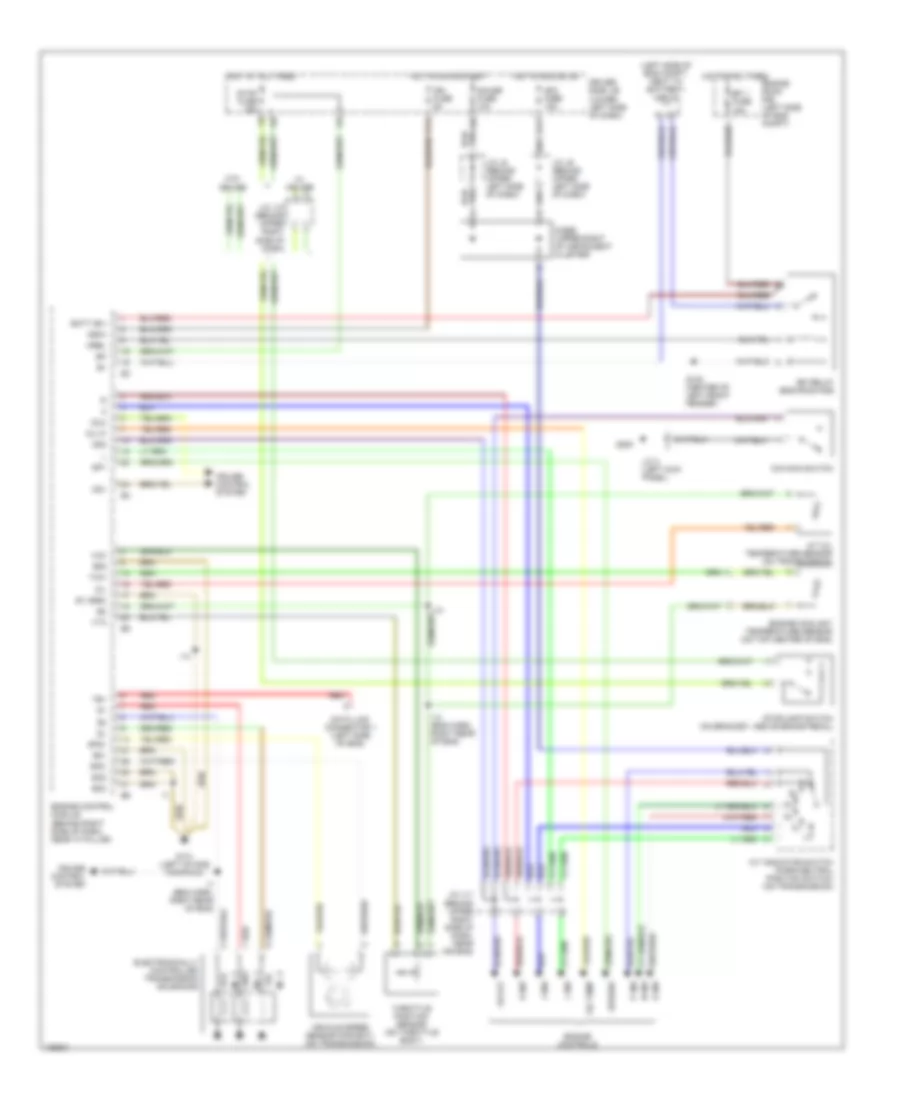
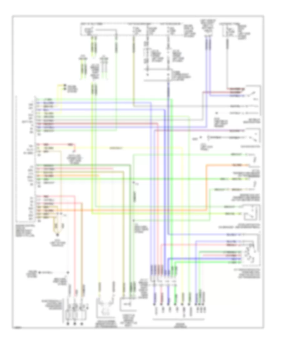
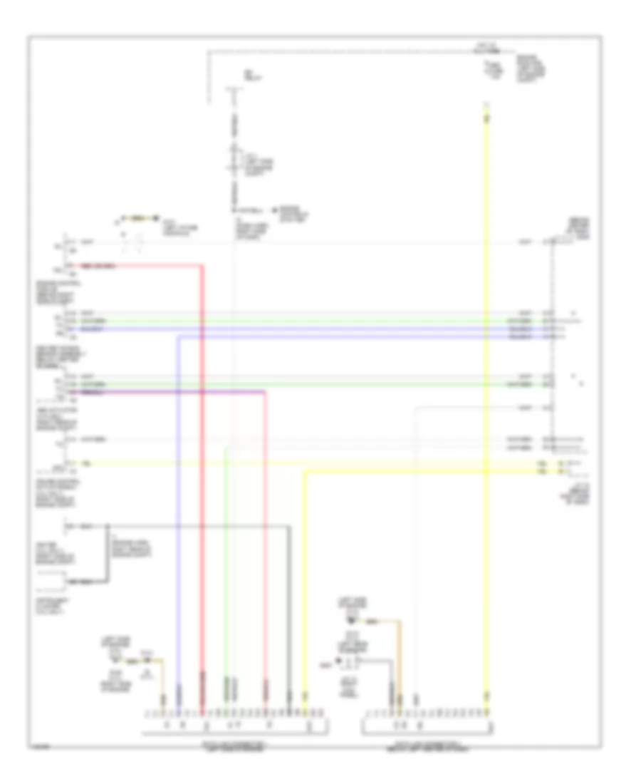
Автомтическая коробка Передач (АКПП) Полная привод (4WD) Блокировка Дифференциала
3.4L
3.4L, Электросхема Полного привода 4WD для Toyota Tundra SR5 2000
 https://portal-diagnostov.com/license.html
Automotive Electricians Portal FZCO
Automotive Electricians Portal FZCO
https://portal-diagnostov.com/license.html
https://portal-diagnostov.com/license.html
Automotive Electricians Portal FZCO
Automotive Electricians Portal FZCO
3.4L, Электросхема Полного привода 4WD для Toyota Tundra SR5 2000 - Список элементов:
- (behind right side of dash) j/c 12
- 4wd
- 4wd fuse 20a
- 4wd ind
- A/t p ind
- Abs actuator with ecu (right rear of engine compt)
- Acc fuse 15a
- Add actuator (left side of trans)
- C11
- C14
- California
- California with a/t
- Combination meter
- Detection switch (4wd position) (transfer case)
- Detection switch (l4 position) (transfer case)
- Detection switch (neutral position) (transfer case)
- Didoe (a/t) (behind center of dash)
- Driver side j/b (lower left side of dash)
- Engine control module (behind right side of dash)
- Ex1
- Ex13
- Except california
- Except california with a/t
- G11
- G203
- Gauge fuse 10a
- Hot in on or acc
- Hot in on or start
- J/c 10 (behind center of dash)
- J/c 13 (right kick panel)
- J/c 6 (behind center of dash)
- J/c 8 (behind center of dash)
- J/c 9 (behind center of dash)
- Neutral position switch (part of park/ neutral position switch)
- Red
- Tfn
- Transmission control relay (at right kick panel)
- W/ abs
- W/ power mirrors
- W/o abs
- W/o power mirrors
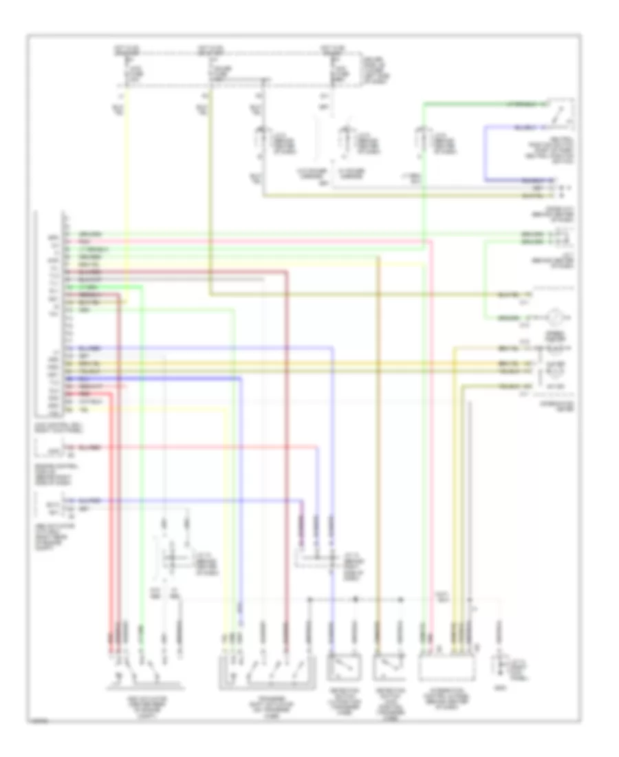
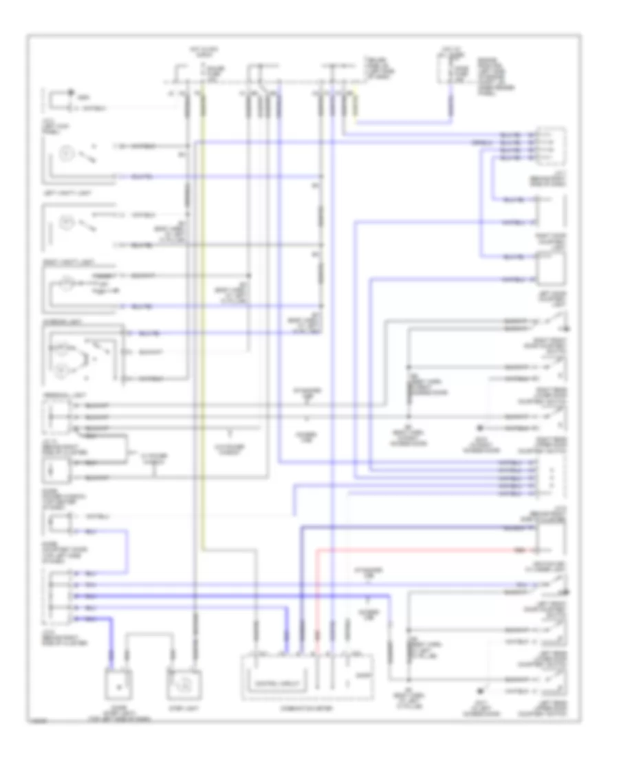
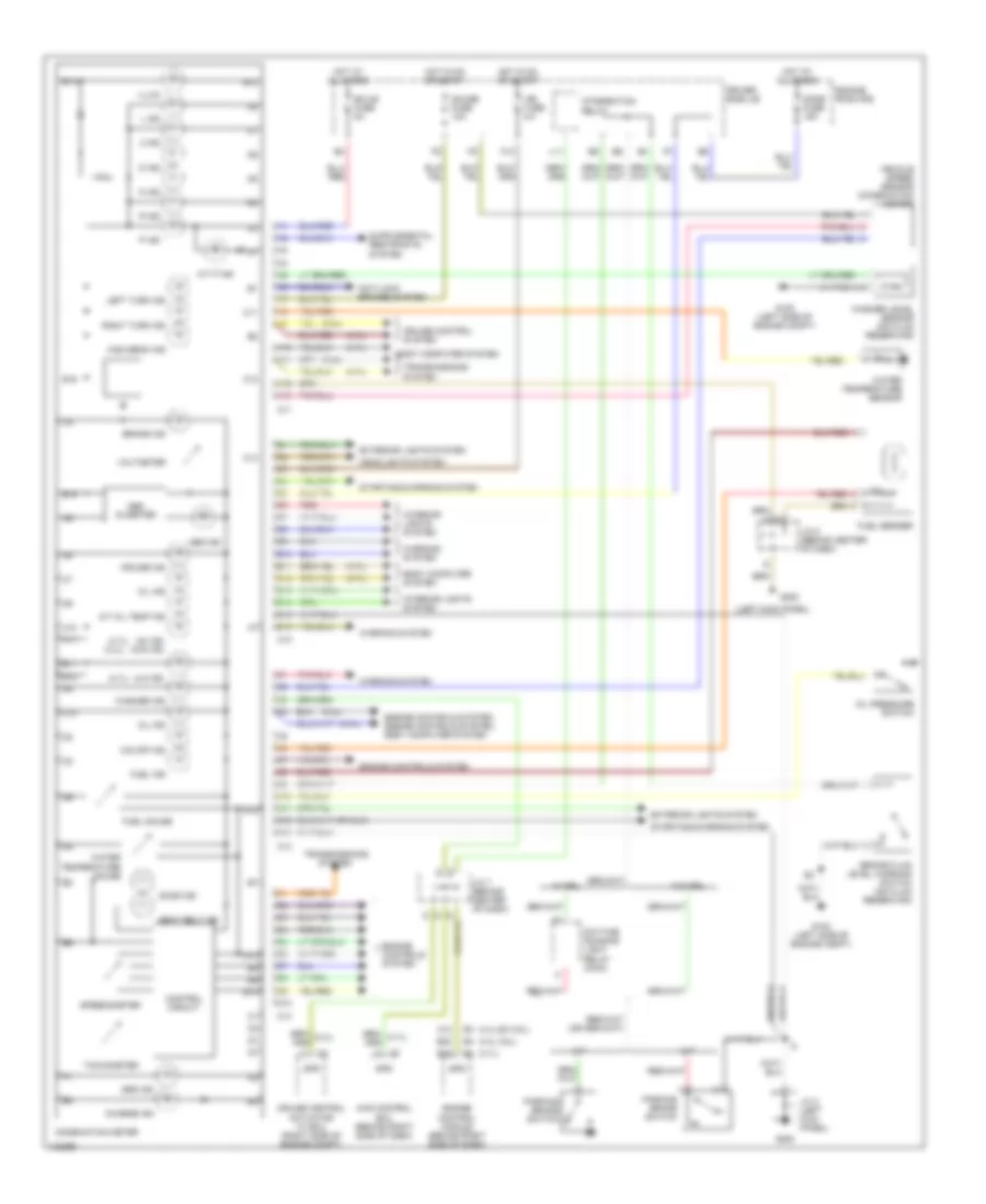
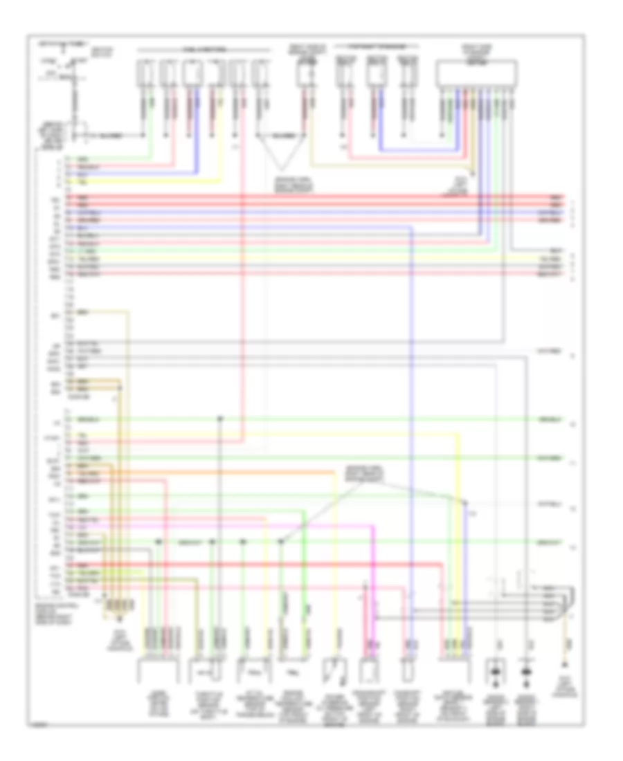
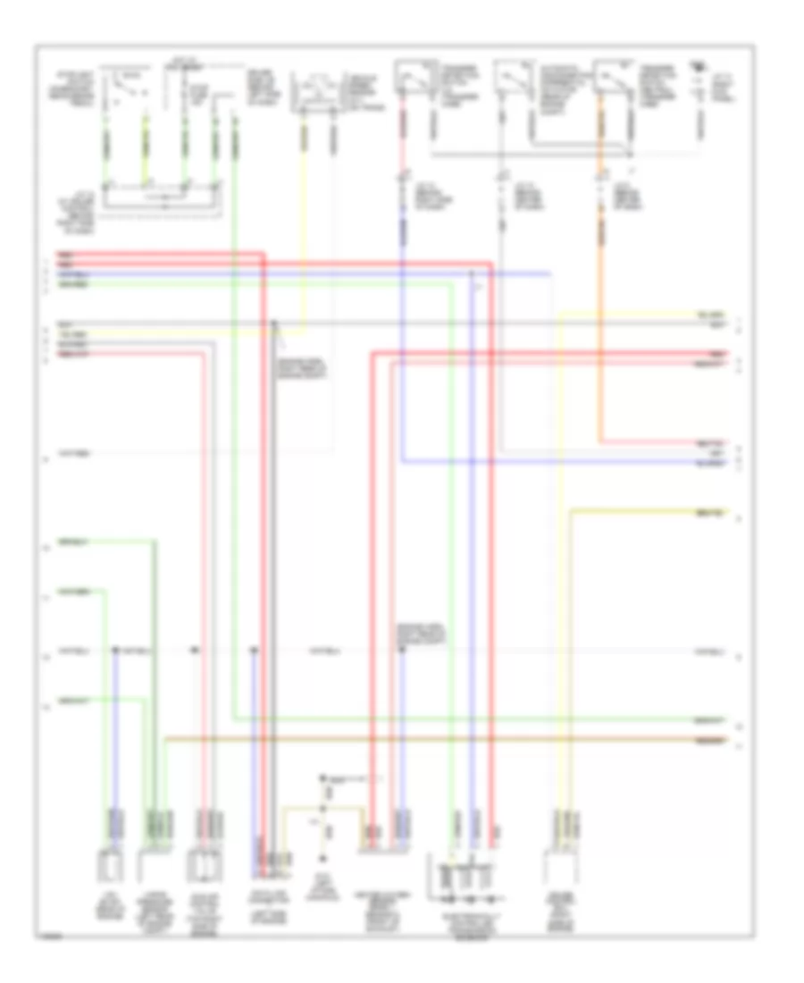
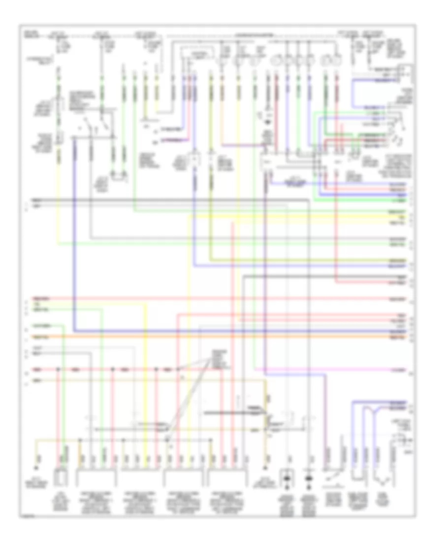
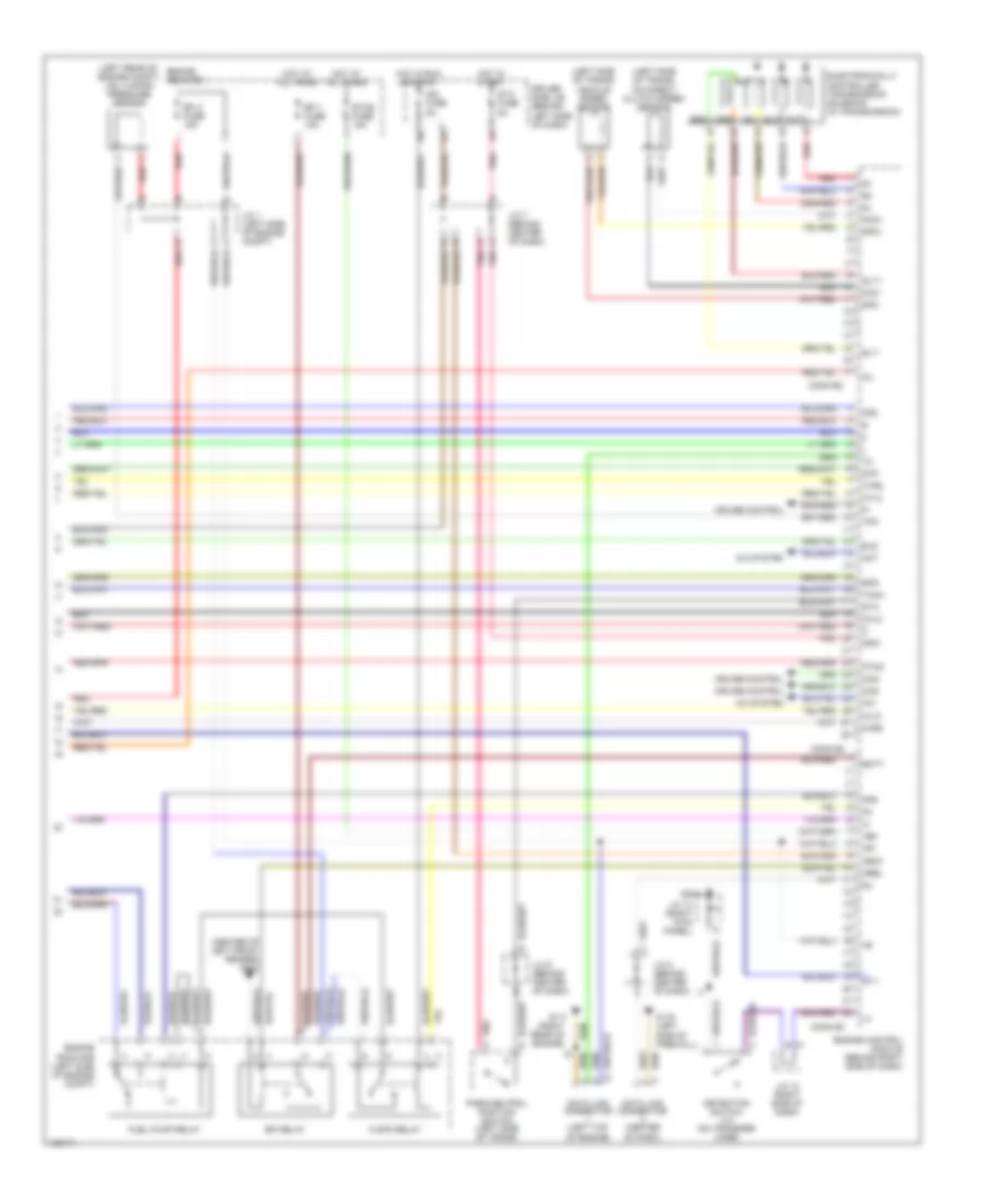
3.4L, Электросхема автоматической коробки передач АКПП, Калифорния для Toyota Tundra SR5 2000
3.4L, Электросхема автоматической коробки передач АКПП, Калифорния для Toyota Tundra SR5 2000 - Список элементов:
- (left side of eng compt, next to battery) j/c j1
- 2 ind
- A/t indicator switch (park/neutral position switch) (on transmission)
- A/t oil temperature sensor (on transmission)
- Acc fuse 15a
- Batt (b+)
- Cruise control system
- D ind
- Data link connector 1 (left side of eng)
- Diode (upper right of instrument cluster)
- Driver side j/b (lower left side of dash)
- E01
- E05
- E1 (grd)
- Efi 1 fuse 15a
- Efi relay (eng room r/b)
- Electronically controlled transmission solenoids
- Engine control module (behind right side of dash, near "a" pillar)
- Engine controls
- Engine coolant temperature sensor (on top center of eng)
- Engine room r/b (left side of eng compt)
- Eo2
- Eo3
- F11
- G100 (center of left front fender)
- G11
- G131 (left intake manifold)
- G200
- Gauge fuse 10a
- Hot at all times
- Hot in acc or on
- Hot in on or start
- I13
- I13 (eng harn, right rear of eng)
- I14
- I7 (eng harn, right rear of eng)
- Idl0
- Ign fuse 5a
- Igsw
- J/c 3 (left kick panel)
- J/c j11 (behind upper right side of dash, near air bag)
- J/c j12 (behind upper right side of dash)
- J/c j8 (behind upper left side of dash)
- J/c j9 (behind upper left side of dash)
- L ind
- Mrel
- N ind
- No. 1
- No. 2
- No. 3
- O/d main switch
- Od off
- Od1
- Od2
- Oil
- Oil temp
- Oil-w
- P ind
- R ind
- Red
- Sp1
- Sp2+
- Sp2-
- Speedo
- Stop fuse 15a
- Stoplamp switch (on bracket, above brake pedal)
- Te1
- Throttle position sensor (on throttle body)
- Thw
- Vcc
- Vehicle speed sensor (for ect) (on transmission)
- Vta
- W/ cruise
- W/o cruise
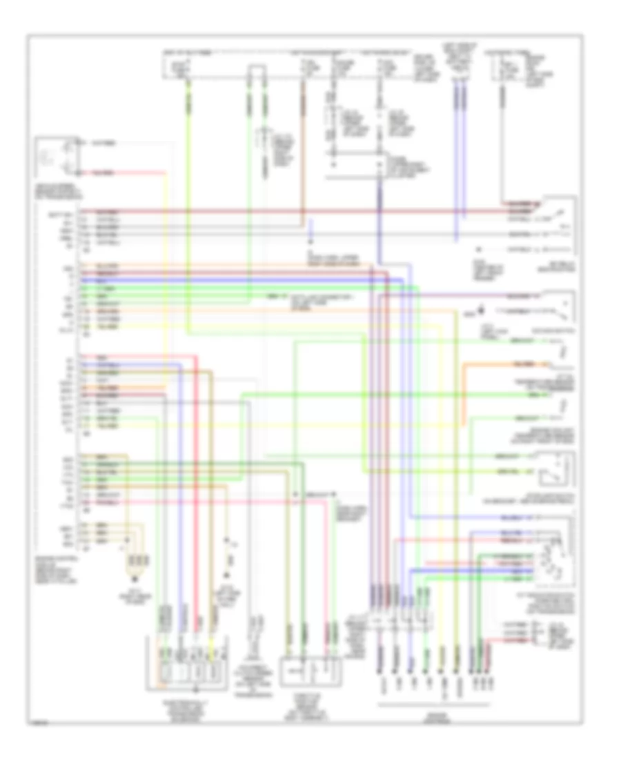
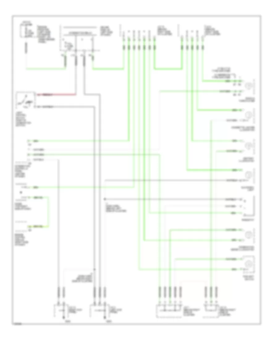
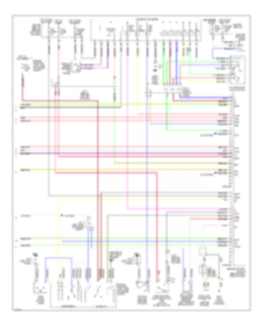
3.4L, Электросхема автоматической коробки передач АКПП, Кроме Калифорнии для Toyota Tundra SR5 2000
3.4L, Электросхема автоматической коробки передач АКПП, Кроме Калифорнии для Toyota Tundra SR5 2000 - Список элементов:
- (4wd only)
- (left side of eng compt, next to battery) j/c j1
- 2 ind
- A/t indicator switch (park/neutral position switch) (on transmission)
- A/t oil temperature sensor (on transmission)
- Acc fuse 15a
- Batt (b+)
- Cruise control system
- D ind
- Data link connector 1 (left side of eng)
- Diode (upper right of instrument cluster)
- Driver side j/b (lower left side of dash)
- E01
- E1 (grd)
- Efi 1 fuse 15a
- Efi relay (eng room r/b)
- Electronically controlled transmission solenoids
- Engine control module (behind right side of dash, near "a" pillar)
- Engine controls
- Engine coolant temperature sensor (on top center of eng)
- Engine room r/b (left side of eng compt)
- Eo2
- Eo3
- F11
- G100 (center of left front fender)
- G11
- G131 (left intake manifold)
- G200
- Gauge fuse 10a
- Hot at all times
- Hot in acc or on
- Hot in on or start
- I13
- I13 (eng harn, right rear of eng)
- I14
- I7 (eng harn, right rear of eng)
- Idl0
- Ign fuse 5a
- J/c 3 (left kick panel)
- J/c j11 (behind upper right side of dash, near air bag)
- J/c j12 (behind upper right side of dash)
- J/c j8 (behind upper left side of dash)
- J/c j9 (behind upper left side of dash)
- L ind
- N ind
- No. 1
- No. 2
- No. 3
- O/d main switch
- Od off
- Od1
- Od2
- Oil
- Oil temp
- Oil-w
- P ind
- R ind
- Red
- Sp1
- Sp2+
- Sp2-
- Speedo
- Stop fuse 15a
- Stoplamp switch (on bracket, above brake pedal)
- Te1
- Throttle position sensor (on throttle body)
- Thw
- Vehicle speed sensor (for ect) (on transmission)
- Vta
- W/ cruise
- W/o cruise
4.7L
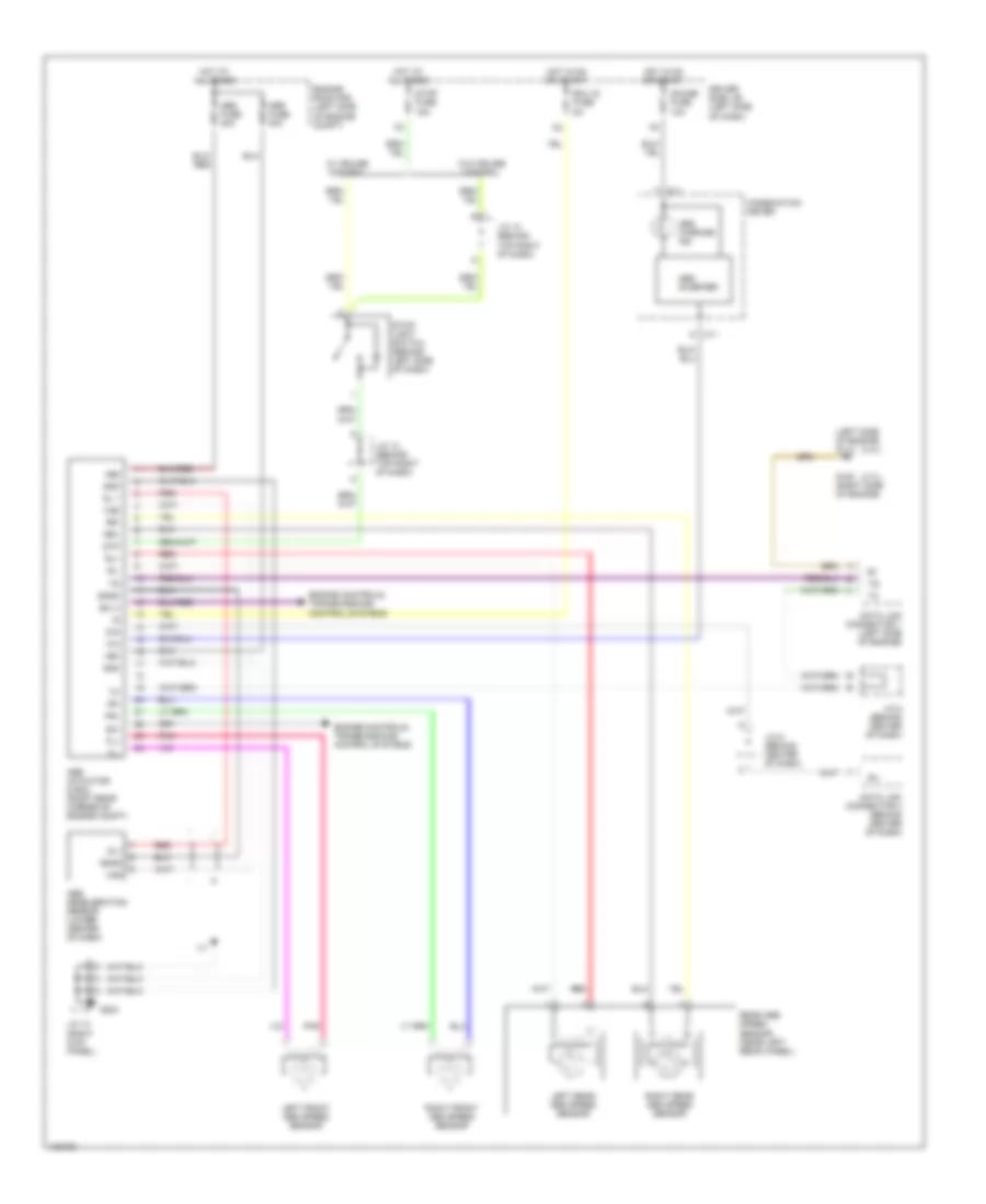
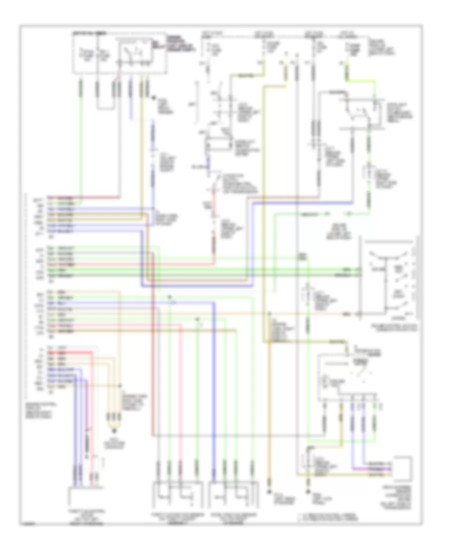
4.7L, Электросхема Полного привода 4WD для Toyota Tundra SR5 2000
4.7L, Электросхема Полного привода 4WD для Toyota Tundra SR5 2000 - Список элементов:
- (behind center of dash)
- (behind right side of dash)
- 2-4
- 4hi ind
- 4lo ind
- 4wd
- 4wd control ecu (right kick panel)
- 4wd fuse 20a
- Abs actuator with ecu (right rear of engine compt)
- Acc fuse 15a
- Add
- Add actuator (center rear of engine compt)
- C11
- C12
- C13
- Combination meter
- Detection switch (4wd positon) (transfer case)
- Detection switch (l4 position) (transfer case)
- Didoe (a/t) (behind center of dash)
- Dl1
- Dl2
- Dm1
- Dm2
- Driver side j/b (lower left side of dash)
- Engine control module (behind right side of dash)
- Ex1
- Ex13
- G11
- G203
- Gauge fuse 10a
- Gnd
- H-l
- Hot in on or acc
- Hot in on or start
- I24
- Ind1
- Ind2
- Integration control & panel (behind center of dash)
- J/c 10
- J/c 12
- J/c 13 (right kick panel)
- J/c 6 (behind center of dash)
- J/c 7 (behind center of dash)
- J/c 8 (behind center of dash)
- J/c 9 (behind center of dash)
- Neutral position switch (part of park/ neutral position switch)
- Pnk
- Red
- Spd
- Speed- ometer
- Tl1
- Tl2
- Tl3
- Tm1
- Tm2
- Transfer shift actuator (on transfer case)
- W/ abs
- W/ power mirrors
- W/o abs
- W/o power mirrors
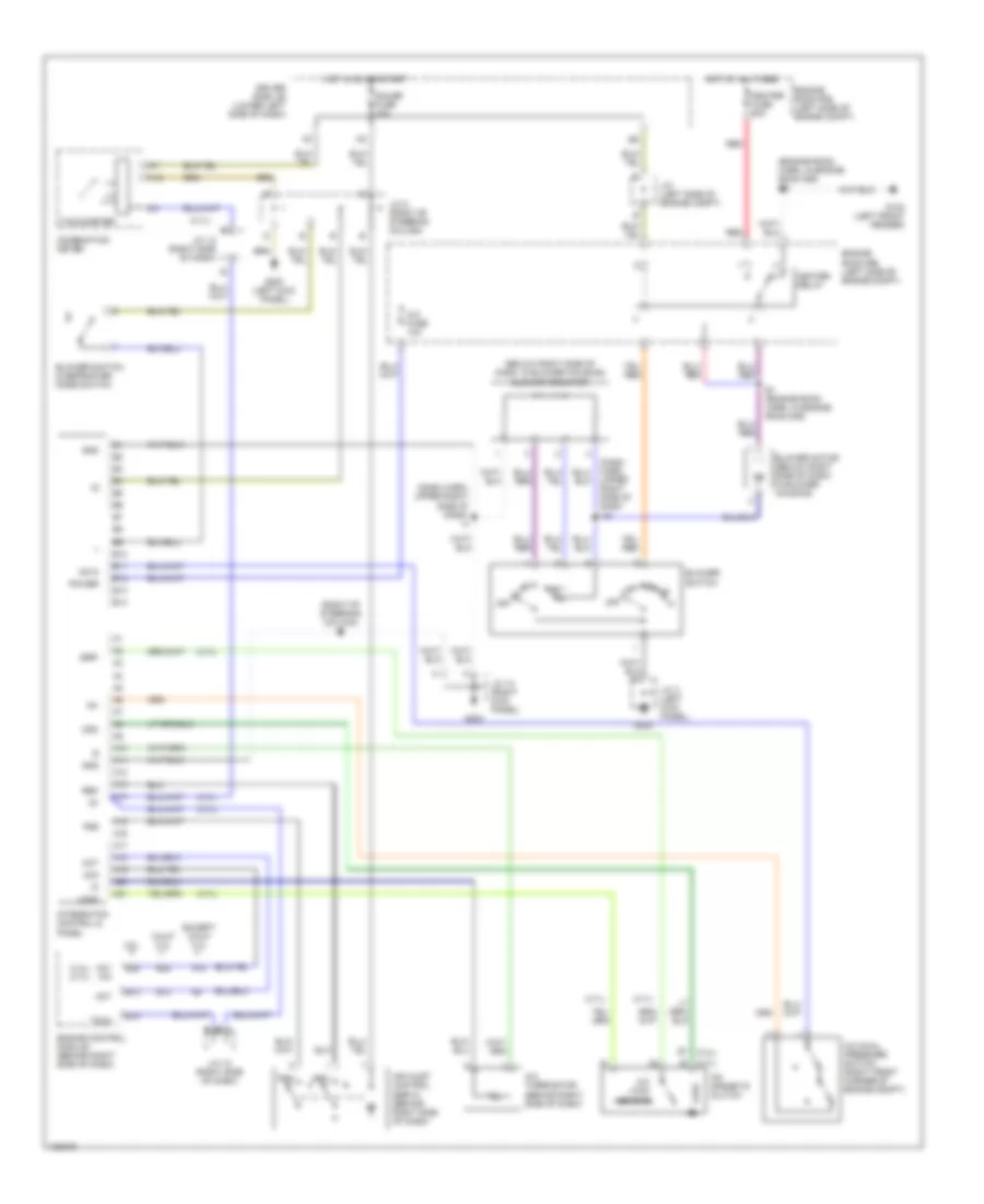
4.7L, Электросхема автоматической коробки передач АКПП для Toyota Tundra SR5 2000
4.7L, Электросхема автоматической коробки передач АКПП для Toyota Tundra SR5 2000 - Список элементов:
- (left side of eng compt, next to battery) j/c j1
- 2 ind
- A/t indicator switch (park/neutral position switch) (on transmission)
- A/t oil temperature sensor (on transmission)
- Acc fuse 15a
- B+1
- Batt (b+)
- D ind
- Data link connector 1 (on left side of eng)
- Diode (upper right of instrument cluster)
- Driver side j/b (lower left side of dash)
- E01
- Efi 1 fuse 15a
- Efi relay (eng room r/b)
- Electronically controlled transmission solenoids
- Engine control module (behind right side of dash, near "a" pillar)
- Engine controls
- Engine coolant temperature sensor (on right front of eng)
- Engine room r/b (left side of eng compt)
- Eo2
- Eo3
- F11
- G100 (center of left front fender)
- G11
- G116 (left side of fire- wall)
- G117 (right rear of eng)
- G200
- Gauge fuse 10a
- Hot at all times
- Hot in acc or on
- Hot in on or start
- I10
- I5 (dash harn, upper right side of dash)
- I7 (dash harn, near right grommet)
- Ign fuse 5a
- Igsw
- J/c 3 (left kick panel)
- J/c j11 (behind upper right side of dash, near air bag)
- J/c j12 (behind upper right side of dash)
- J/c j8 (behind upper left side of dash)
- J/c j9 (behind upper left side of dash)
- L ind
- Meo1
- Mrel
- N ind
- Nco+
- Nco-
- No. 1
- No. 2
- No. 3
- O/d direct clutch speed sensor (on left side of transmission)
- O/d main switch
- Od off
- Od2
- Oil
- Oil temp
- Oil-w
- P ind
- R ind
- Red
- Slt
- Slt+
- Slt-
- Sp2+
- Sp2-
- Spd
- Speedo
- Stop fuse 15a
- Stoplamp switch (on bracket, above brake pedal)
- Te1
- Throttle position sensor (on throttle body assembly)
- Thw
- Vcc
- Vehicle speed sensor (for ect) (on transmission)
- Vta
- Vta2
БЛОК ПРЕДОХРАНИТЕЛЕЙ И РЕЛЕ
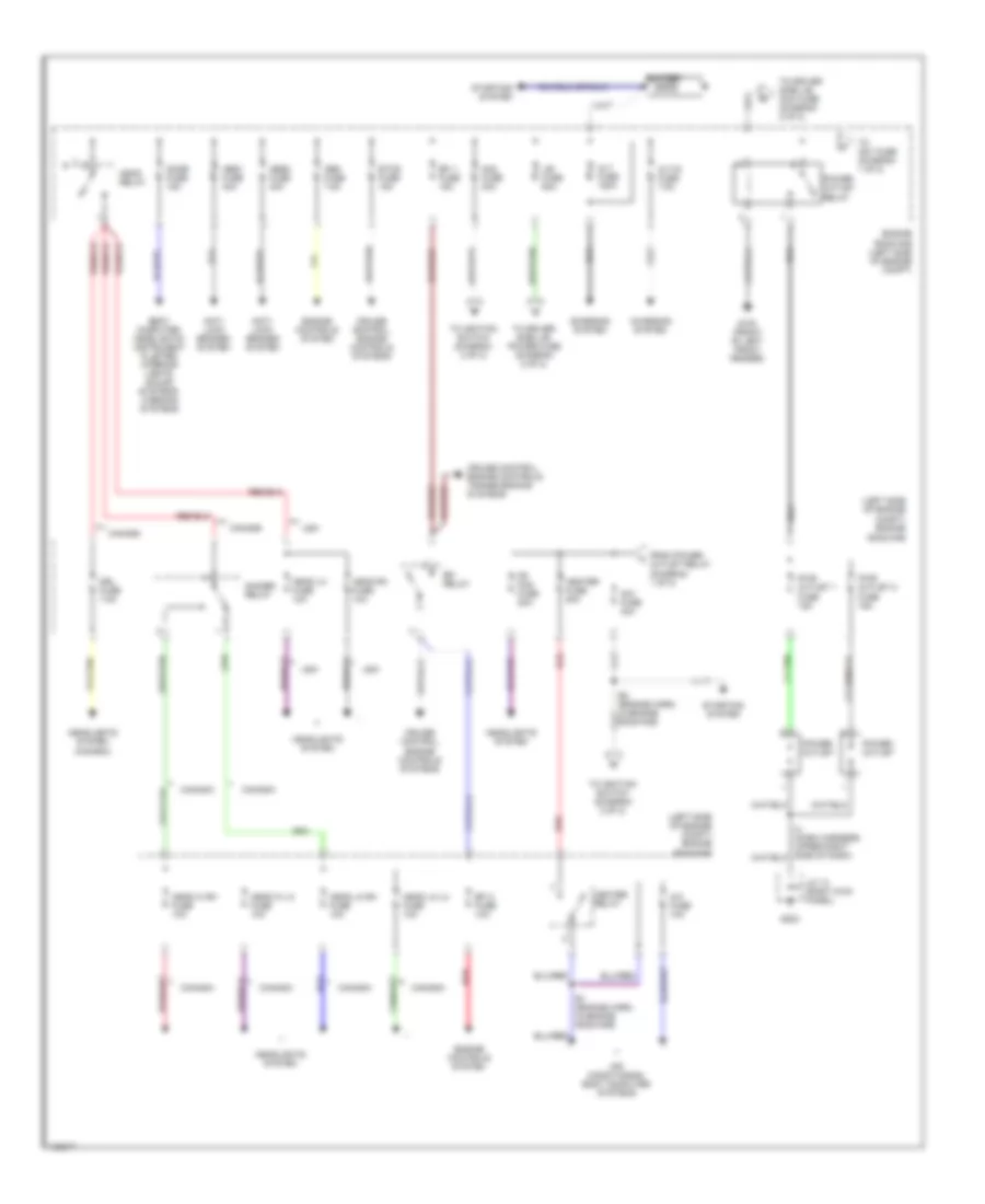
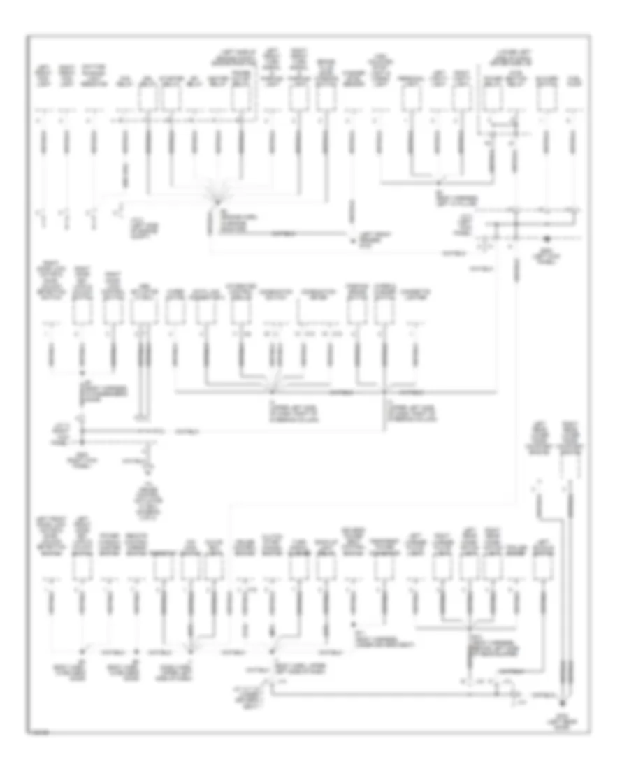
Электросхема блока предохранителей и реле (1 из 2) для Toyota Tundra SR5 2000
Электросхема блока предохранителей и реле (1 из 2) для Toyota Tundra SR5 2000 - Список элементов:
- (left side of engine compt) engine
- A/c fuse 10a
- Abs1 fuse 40a
- Abs2 fuse 40a
- Air conditioning, body computer systems
- Alt fuse 120a
- Alt-s fuse 7.5a
- Am1 fuse 40a
- Am2 fuse 30a
- Anti- lock brakes system
- Battery
- Body computer, headlights, instrument cluster, interior lights, sound systems, warning systems
- Canada
- Charging system
- Cruise control, engine controls systems
- Cruise control, engine controls, transmissions systems
- Dimmer relay
- Dome fuse 15a
- Drl fuse 7.5a
- E1 (engine harn, in engine room r/b)
- Efi 1 fuse 15a
- Efi 2 fuse 10a
- Efi relay
- Engine
- Engine controls system
- Etcs fuse 15a
- Fr fog fuse 20a
- From power outlet relay (diagram 1 of 2)
- G100 (front of left front fender)
- G203
- Head hi lh fuse 10a
- Head hi rh fuse 10a
- Head lh fuse 10a
- Head lo lh fuse 10a
- Head lo rh fuse 10a
- Head relay
- Head rh fuse 10a
- Headlights system
- Headlights system (canada)
- Heater fuse 50a
- Heater relay
- I4 (dash harness, upper right side of dash)
- J/b fuse 50a
- J/c 13 (right kick panel)
- Obd fuse 7.5a
- Power outlet
- Power outlet relay
- Pwr outlet 1 fuse 15a
- Pwr outlet 2 fuse 15a
- Red
- Room r/b
- Room r/b (left side of engine compt)
- Starting system
- To am1 fuse (diagram 1 of 2)
- To driver side j/b, acc fuse (diagram 2 of 2)
- To driver side j/b, power fuse (diagram 2 of 2)
- To ignition switch (diagram 2 of 2)
- Usa
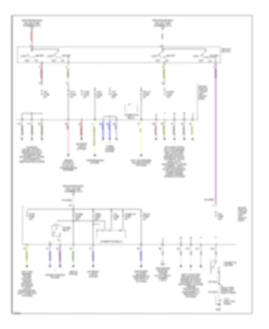
Электросхема блока предохранителей и реле (2 из 2) для Toyota Tundra SR5 2000
Электросхема блока предохранителей и реле (2 из 2) для Toyota Tundra SR5 2000 - Список элементов:
- 4wd fuse 20a
- Acc
- Acc fuse 15a
- Air conditioning, anti-lock brakes, body computer, cruise control, engine controls, exterior lights, headlights, instrument cluster, interior lights, starting/charging, transmissions, wiper/washer, warning systems
- Anti-lock brakes, cruise control systems
- Anti-lock brakes, cruise control, engine controls, exterior lights, transmissions, shift interlock systems
- Cargo lp fuse 5a
- Cigarette lighter
- Driver side j/b (lower left side of dash)
- Ecu-b fuse 5a
- Ecu-ig fuse 5a
- Engine controls, starting, transmissions systems
- Exterior lights system
- F10
- F11
- From engine room r/b, am1 fuse (diagram 1 of 2)
- From engine room r/b, am2 fuse (diagram 1 of 2)
- From engine room r/b, j/b fuse (diagram 1 of 2)
- From engine room r/b, power outlet relay (diagram 1 of 2)
- G10
- G11
- G12
- G200
- Gauge fuse 10a
- Horn fuse 20a
- I2 (dash harn, upper left side of dash)
- Ign fuse 5a
- Ignition switch
- Integration relay
- J/c 3 (left kick panel)
- Lock
- Pnk
- Power fuse 30a
- Power relay
- Power windows system
- Seats system
- Sta fuse 5a
- Start
- Stop fuse 15a
- Tail fuse 15a
- Transmissions system
- Turn fuse 5a
- Wip fuse 20a
- Wiper/ washer system
ВНЕШНЕЕ ОСВЕЩЕНИЕ
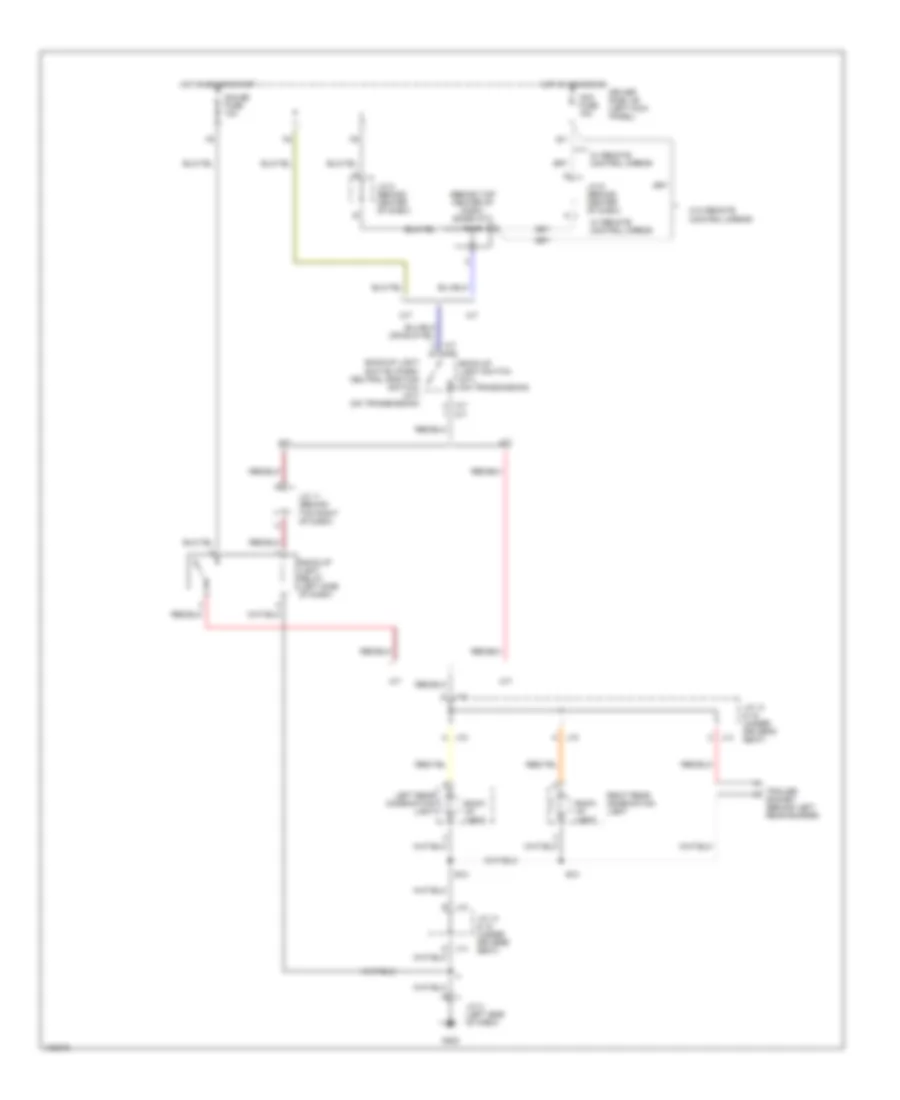
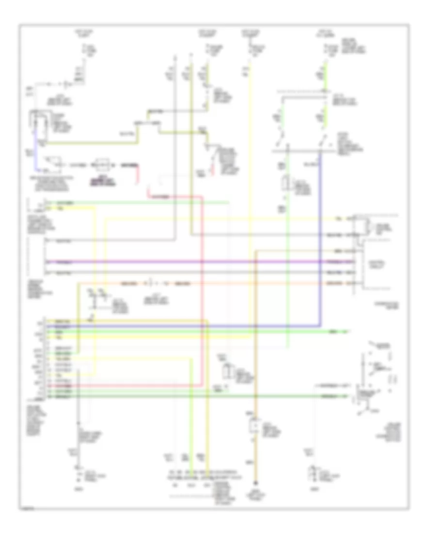
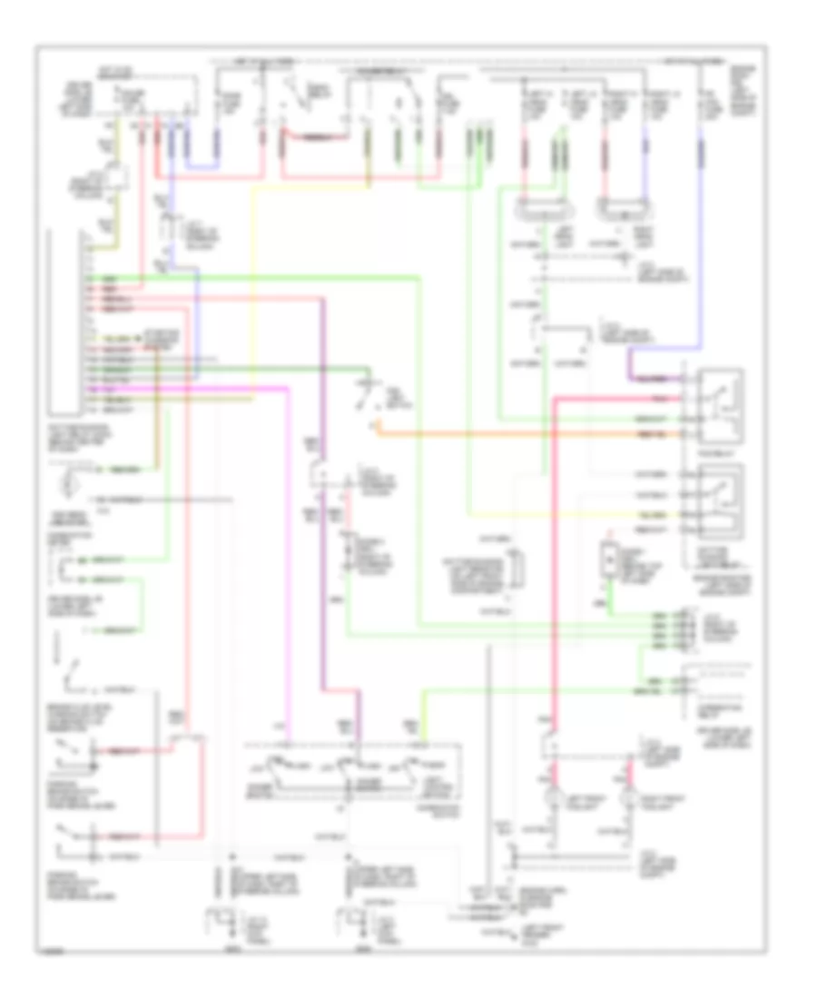
Электросхема заднего хода для Toyota Tundra SR5 2000
Электросхема заднего хода для Toyota Tundra SR5 2000 - Список элементов:
- (behind top center of dash) diode (a/t)
- A/t
- A/t m/t
- Acc fuse 15a
- B10
- Back- up light
- Back-up light relay (left side of dash)
- Back-up light switch (m/t) (on transmission)
- Back-up light switch (park/ neutral position switch) (a/t) (on transmission)
- Driver side j/b (left kick panel)
- G11
- G202
- Gauge fuse 10a
- Hot in acc or on
- Hot in on or start
- J/c 11 (behind top right of dash)
- J/c 14 & 15 (under driver's seat)
- J/c 3 (left side of dash)
- J/c 8 (behind center of dash)
- J/c 9 (behind center of dash)
- J14 c
- J15 a
- J15 e
- Left rear combination light
- M/t
- Right rear combination light
- Socket (behind left rear bumper)
- Trailer
- W/ remote control mirror
- W/o remote control mirror
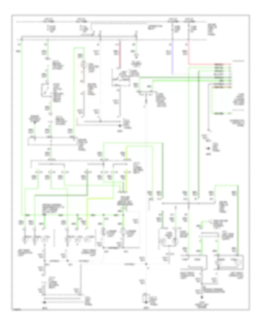
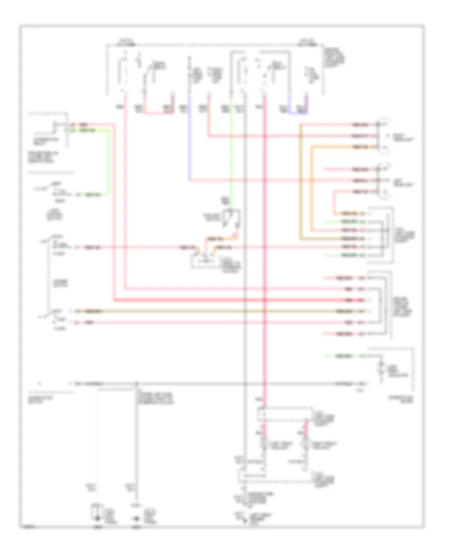
Электросхема внешнего освещения для Toyota Tundra SR5 2000
Электросхема внешнего освещения для Toyota Tundra SR5 2000 - Список элементов:
- (frame harness, near breakout to left license plate light) b10
- B j14
- B j15
- B10
- C j15
- C12
- C13
- Comb- ination meter
- Comb- ination switch
- D j15
- D10
- D11
- Driver side j/b (left kick panel)
- E11
- E3 (engine harness, in engine room r/b)
- Engine controls system
- From driver side j/b (diagram 1 of 1)
- G100 (front left fender)
- G200
- G203
- H13
- Head
- High mounted stop- light
- Horn fuse 20a
- Hot at all times
- Integration control & panel
- Integration relay
- J/c 1 (left side of engine compt)
- J/c 12 (behind top right of dash)
- J/c 13 (right kick panel)
- J/c 14 & 15 (under driver's seat)
- J/c 14, & 15 (under driver's seat)
- J/c 3 (left kick panel)
- J14 a
- J14 e
- J15 b
- J15 c
- J15 d
- L13
- Left front combination light
- Left rear combination light
- License plate light
- Light ctrl switch
- Off
- Park
- Right front combination light
- Right rear combination light
- Stop
- Stop fuse 15a
- Stop- light switch (on bracket, above brake pedal)
- Tail
- Tail fuse 15a
- To j/c 1 (diagram 1 of 1)
- Trailer socket (behind left rear bumper)
- Turn
- Turn fuse 5a
- Turn signal flasher (left side of dash)
- Turn signal ind
- Turn signal switch (comb- ination switch)
ВНУТРЕННЕЕ ОСВЕЩЕНИЕ
Электросхема подсветки для Toyota Tundra SR5 2000
Электросхема подсветки для Toyota Tundra SR5 2000 - Список элементов:
- Access cab
- B4 (body harn, at left "a" pillar)
- B9 (body harn, in right access door)
- C11
- C12
- Combination meter
- Control circuit
- Diode (courtesy door) (top left side of dash)
- Diode (power window) (top center of dash)
- Diode (step light) (top left side of dash)
- Dome fuse 15a
- Door
- Driver side j/b (left side of dash)
- Engine room r/b (left side of engine compt, on inner fender panel)
- G200
- G315 (in right access door)
- G317 (in left access door)
- Gauge fuse 10a
- Hot at all times
- Hot in acc & run
- Ignition key cylinder light
- Interior light
- J/c 10 (behind right side of cluster)
- J/c 3 (left kick panel)
- J/c 7 (behing right side of dash)
- J/c 9 (behind right side of cluster)
- Left door courtesy light
- Left front door courtesy switch
- Left rear lower door courtesy switch
- Left rear upper door courtesy switch
- Left vanity light
- Off
- Personal light
- Red
- Right door courtesy light
- Right front door courtesy switch
- Right rear lower door courtesy switch
- Right rear upper door courtesy switch
- Right vanity light
- Standard cab
- Step light
- W/ power window
- W/o power window
Электросхема подсветки приборов для Toyota Tundra SR5 2000
Электросхема подсветки приборов для Toyota Tundra SR5 2000 - Список элементов:
- Ashtray illumination
- C c
- Cigarette lighter illumination
- Combination meter illumination
- Diode (top right side of dash)
- Driver side j/b (left side of dash)
- Engine room r/b (left side of engine compt, on inner fender panel)
- Engine control module (right side of dash)
- Foglight switch
- G200
- G202
- Glove box light
- Head
- Hot at all times
- I1 dash harn, (behind left side of cluster)
- I2 (dash harn, behind right side of cluster)
- I24
- I25
- Integration control & panel (center of dash)
- Integration relay
- J/b fuse 50a
- J/c 10 (behind right side of cluster)
- J/c 13 (right kick panel)
- J/c 3 (left kick panel)
- J/c 7 (behind right side of cluster)
- J/c 8 (behind right side of cluster)
- Light control switch (part of combination switch)
- Off
- Radio & tape player
- Rheostat
- Tail
- Tail fuse 15a
- W/ built-in type amplifier
- W/ seperate type amplifier
ЗАЗЕМЛЕНИЕ ПОДКЛЮЧЕНИЕ МАССЫ
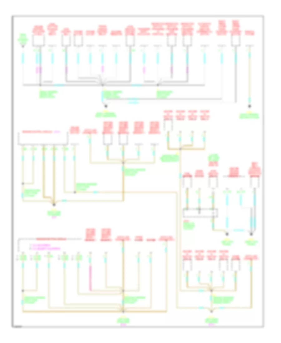
Электросхема подключение массы заземления (1 из 2) для Toyota Tundra SR5 2000
Электросхема подключение массы заземления (1 из 2) для Toyota Tundra SR5 2000 - Список элементов:
- (3.4l)
- (a/t)
- (left front fender) g102
- (left side of engine compt) engine room r/b
- (lower left side of dash) driver side j/b
- (m/t)
- (w/o drl)
- Abs actuator w/ ecu
- B10 (body harness, behind left side of rear bumper)
- B11 (body harness, under driver's seat)
- B2 (body harn, in driver's door)
- B3 (body harn, in driver's door)
- B7 (body harness, in passenger's door)
- Back-up light relay
- Blower switch
- Brake fluid level warning switch
- C12
- C13
- C16
- Cigarette lighter
- Clutch start cancel switch
- Combination meter
- Combinaton switch
- Cruise control switch
- Data link connector 3
- Daytime
- Driver's power seat control switch
- Drl relay
- E3 (body harness, left "a" pillar)
- E3 (engine harn, in engine room r/b)
- Efi relay
- Fog relay
- Fuel pump
- G200 (left kick panel)
- G203 (right kick panel)
- G700 (left rear door)
- Glove box light
- Heater relay
- High mounted stop- light & cargo light
- I1 (body harn, upper left side of dash)
- I1 (dash harn, upper left side of dash)
- I2 (upper left side of dash, right of steering column)
- I24
- Inte- gration relay
- Intigrated control module
- J/c 13 (right kick panel)
- J/c 14 7 15 (under driver's seat)
- J/c 2 (left side of engine compt)
- J/c 3 (left kick panel)
- J14
- J15
- Left buckle switch
- Left front door key lock & unlock switch
- Left front door lock motor & door unlock detection switch
- Left front fog- light
- Left front turn signal & parking light
- Left license plate light
- Left rear combi- nation light
- Left rear lower door courtesy switch
- Left vanity light
- O/d main switch
- Parking brake switch
- Personal light
- Power outlet relay
- Power relay
- Power window master switch
- Remote control mirror switch
- Rheostat
- Right door lock control switch
- Right door key lock & unlock switch
- Right door lock motor & door unlock detection switch
- Right front fog- light
- Right front turn signal & parking light
- Right license plate light
- Right rear combi- nation light
- Right rear lower door courtesy switch
- Right vanity light
- Running light resistor
- Starter relay
- Temporary power connector
- To cruise control actuator w/ ecu (diagran 2 of 2)
- Trailer socket
- Turn signal flasher
- Washer level sensor
- Wiper & washer switch
- Wiper motor
Электросхема подключение массы заземления (2 из 2) для Toyota Tundra SR5 2000
Электросхема подключение массы заземления (2 из 2) для Toyota Tundra SR5 2000 - Список элементов:
- (3.4l)
- (4.7l)
- (engine harness, right side of dash) i10
- (except california)
- (lower left side of dash) driver side j/b
- 3.4l california
- 3.4l except california
- 4wd control ecu
- Automatic discon- necting differential switch
- Blower resistor
- Center air bag sensor assembly
- Combi- nation switch
- Cruise control actuator w/ ecu
- Cruise control switch
- Data link connector 1
- Data link connector 3
- Detection switch (transfer 4wd position)
- Detection switch (transfer l4 position)
- Detection switch (transfer neutral position)
- E5 (engine harn, center rear of engine compt)
- E5 (engine harness, center rear of engine compt)
- Engine control module
- From j/c 13 (diagram 1 of 2)
- Fuel sender
- G112 (left side of engine) (3.4l)
- G114 (left rear of engine) (4.7l)
- G120 (right side of engine) (4.7)
- G200 (left kick panel)
- G203 (right kick panel)
- G206 (dash harness, center of dash)
- G800 (body harness, right rear door)
- Heated oxygen sensor (bank 1, sensor 1)
- Heated oxygen sensor (bank 1, sensor 2)
- Heated oxygen sensor (bank 2, sensor 1)
- Heated oxygen sensor (bank 2, sensor 2)
- I14 (engine harness, right side of dash)
- I25
- I4 (dash harness, upper left side of dash)
- I7 (engine harn, right side of dash)
- I7 (engine harness, right side of dash)
- I9 (engine harness, right side of dash)
- Igniter
- Igniter & ignition coil 1
- Igniter & ignition coil 2
- Igniter & ignition coil 3
- Igniter & ignition coil 4
- Igniter & ignition coil 5
- Igniter & ignition coil 6
- Igniter & ignition coil 7
- Igniter & ignition coil 8
- Inte- gration control & panel
- Inte- gration relay
- J/c 8 (right of steering column)
- L16
- Main daytime running light relay
- Noise filter
- Power outlet
- Radio & player
- Right rear lower door courtesy switch
- Right rear upper door courtesy switch
- Seat belt warning occupant detection sensor
- Trans- mission control relay
- Transfer shift actuator
Звуковой сигнал Гудок
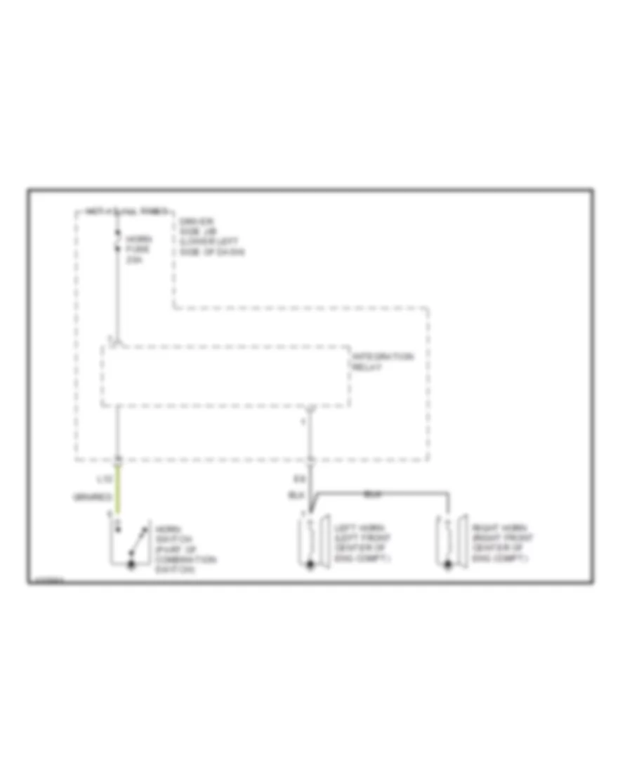
Электросхема звукового сигнал Гудка для Toyota Tundra SR5 2000
Электросхема звукового сигнал Гудка для Toyota Tundra SR5 2000 - Список элементов:
- Driver side j/b (lower left side of dash)
- Horn fuse 20a
- Horn switch (part of combination switch)
- Hot at all times
- Integration relay
- L12
- Left horn (left front center of eng compt)
- Right horn (right front center of eng compt)
Магнитола Мультимедия
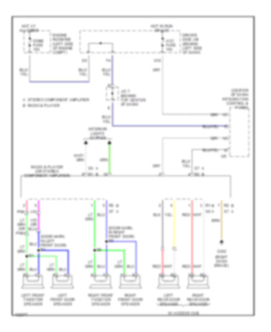
Электросхемы магнитолы для Toyota Tundra SR5 2000
Электросхемы магнитолы для Toyota Tundra SR5 2000 - Список элементов:
- (center of dash) integration control & panel
- (door harn, in left front door) b1
- (door harn, in right front door) b5
- (right dash brace)
- A stereo component amplifier
- Acc fuse 15a
- B radio & player
- Dome fuse 15a
- Driver side j/b (behind left side of dash)
- Engine room r/b (left side of engine compt)
- G10
- G302
- Hot at all times
- Hot in run or acc
- I25
- Interior lights system
- J/c 7 (behind top center of dash)
- Left front door speaker
- Left front tweeter speaker
- Left rear door speaker
- Pnk
- Radio & player (or stereo component amplifier)
- Red
- Right front door speaker
- Right front tweeter speaker
- Right rear door speaker
- W/ access cab
ПОДУШКИ БЕЗОПАСНОСТИ AIR BAG
Электросхема подушек безопасности SRS AirBag для Toyota Tundra SR5 2000
Электросхема подушек безопасности SRS AirBag для Toyota Tundra SR5 2000 - Список элементов:
- A10
- A11
- A12
- Acc
- Acc fuse 15a
- Air bag squib (front passenger air bag assembly)
- Air bag squib (steering wheel pad)
- B10
- B11
- B12
- B13
- B14
- B15
- B16
- B17
- B18
- B19
- B20
- B21
- B22
- B23
- B24
- B25
- B26
- B27
- B28
- C10
- C11
- C12
- Center air bag sensor assembly (behind lower center of dash)
- Combination meter
- Connection detection pin
- Data link connector 1 (top left side of engine)
- Data link connector 3 (below left center of dash)
- Driver side j/b
- Ecu+
- Ecu-
- Ecu-b fuse 5a
- G10
- G200 (left kick panel)
- G203
- G203 (right kick panel)
- Gnd
- Gnd1
- Hot at all times
- Hot in acc or on
- Hot in on or start
- I24
- I25
- Ig2
- Ign fuse 5a
- Ind
- Integration control & panel (behind center of dash)
- J/c 13 (right kick panel)
- J/c 5 (behind left side of dash)
- Left front air bag sensor (on left front corner of engine compt)
- Left pretensioner
- Passenger air bag manual on-off switch
- Pind
- Pl+
- Pl-
- Red
- Right front air bag sensor (on right front corner of engine compt)
- Right pretensioner
- Rr+
- Rr-
- Sil
- Sl-
- Spiral cable
- Sqb+
- Sqb-
- Sr+
- Sr-
- Srs warning light
ПРЕДУПРЕЖДАЮЩИЕ СИСТЕМЫ
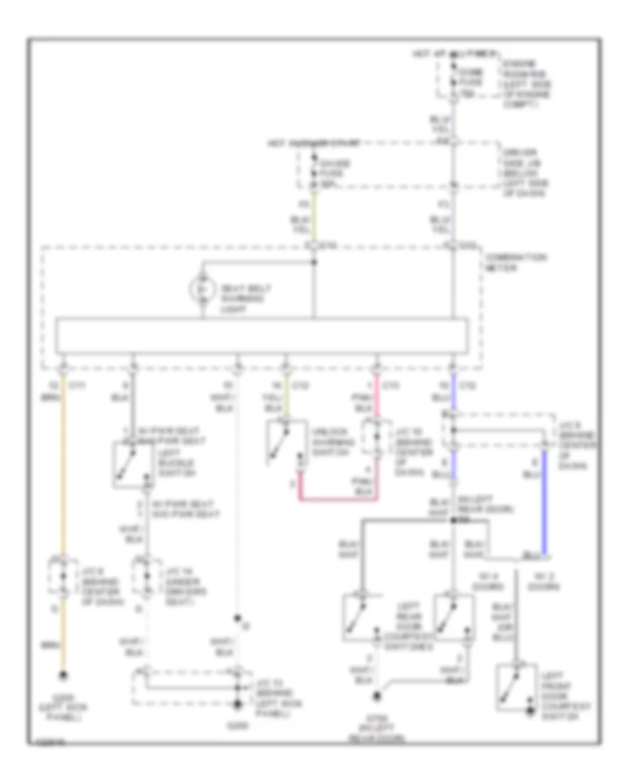
Электросхема предупреждающей системы для Toyota Tundra SR5 2000
Электросхема предупреждающей системы для Toyota Tundra SR5 2000 - Список элементов:
- C11
- C12
- C13
- Combination meter
- Dome fuse 15a
- Driver side j/b (below left side of dash)
- Engine room r/b (left side of engine compt)
- G200
- G200 (left kick panel)
- G700 (in left rear door)
- Gauge fuse 10a
- Hot at all times
- Hot in on or start
- J/c 10 (behind center of dash)
- J/c 13 (behind left kick panel)
- J/c 14 (under driver's seat)
- J/c 8 (behind center of dash)
- J/c 9 (behind center of dash)
- Left buckle switch
- Left front door courtesy switch
- Left rear door courtesy switches
- Seat belt warning light
- Unlock warning switch
- W/ 2 doors
- W/ 4 doors
- W/ pwr seat w/o pwr seat
ПРИБОРНАЯ ПАНЕЛЬ
Электросхема панели приборов для Toyota Tundra SR5 2000
Электросхема панели приборов для Toyota Tundra SR5 2000 - Список элементов:
- (3.4l cal)
- (3.4l ex cal)
- (3.4l)
- (4.7l)
- (4.7l) (3.4l)
- (left kick panel)
- 2 ind
- 4hi ind 4wd ind
- 4lo ind
- 4wd control ecu (behind right side of dash)
- A/t
- A/t oil temp ind
- A/t p ind
- A10
- A11
- A12
- A13
- Abs ind
- Abs inverter
- Anti-lock brakes system
- B10
- B11
- B12
- B13
- B14
- B15
- B16
- B22
- Body computer system
- Brake fluid level warning switch (on fluid reservoir)
- Brake ind
- C10
- C11
- C12
- C13
- C14
- Charge ind
- Combination meter
- Control circuit
- Cruise control actuator w/ ecu (right side of engine compt)
- Cruise control system
- Cruise ind
- D ind
- D10
- Daytime running light relay (main)
- Dome fuse 15a
- Door ind
- Driver side j/b
- Ecu-b fuse 5a
- Engine control module (behind right side of dash)
- Engine controls system
- Engine controls system engine controls system, body computer system
- Engine room r/b
- Exterior lights system
- F10
- Fuel gauge
- Fuel ind
- Fuel sender
- G100 (left side of engine compt)
- G200
- Gauge fuse 10a
- Headlights system
- High beam ind
- Hot at all times
- Hot in on or start
- Ign fuse 5a
- Illum
- Integration relay
- Interior lights system
- J/c 3 (left kick panel)
- J/c 7 (behind center of dash)
- J/c 8 (behind center of dash)
- L ind
- L11
- Left turn ind
- M/t
- Mil ind
- N ind
- O/d off ind
- Oil ind
- Oil pressure switch
- P ind
- Parking brake switch
- R ind
- Red
- Right turn ind
- Seat belt ind
- Spd
- Speedometer
- Srs ind
- Starting/charging system
- Tachometer
- Transmissions system
- Vehicle speed sensor (combination meter)
- Voltmeter
- W/ drl
- W/o drl
- Warning system
- Washer ind
- Washer level sensor (on fluid reservoir)
- Water temperature gauge
- Water temperature sensor
ПРИВОД ЗЕРКАЛ
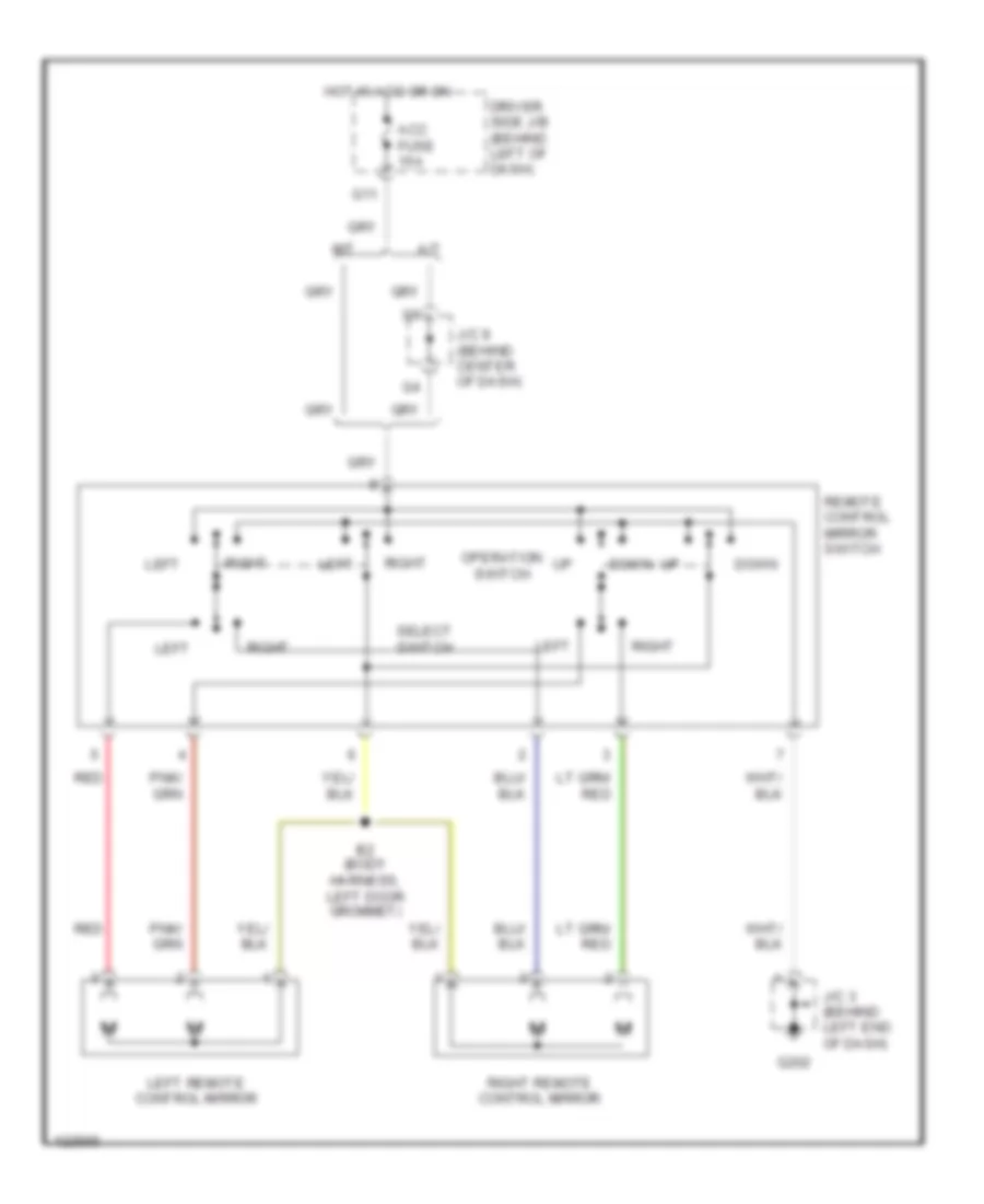
Электросхема привода зеркал для Toyota Tundra SR5 2000
Электросхема привода зеркал для Toyota Tundra SR5 2000 - Список элементов:
- A/t
- Acc fuse 15a
- B2 (body harness, left door grommet)
- Down
- Driver side j/b (behind left of dash)
- G11
- G202
- Hot in acc or on
- J/c 3 (behind left end of dash)
- J/c 9 (behind center of dash)
- Left
- Left remote control mirror
- M/t
- Operation switch
- Red
- Remote control mirror switch
- Right
- Right remote control mirror
- Select switch
ПРИВОД СТЕКЛОПОДЪЕМНИКОВ
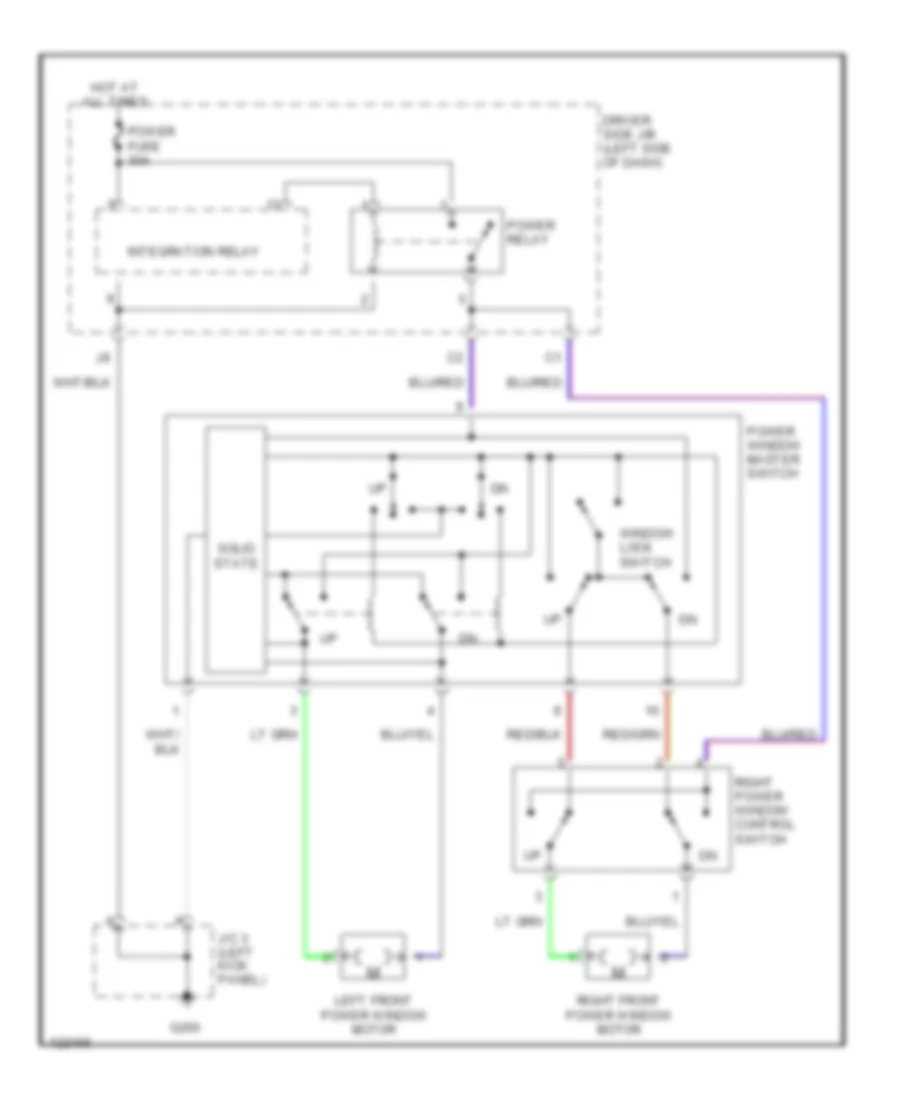
Электросхема стеклоподъемников для Toyota Tundra SR5 2000
Электросхема стеклоподъемников для Toyota Tundra SR5 2000 - Список элементов:
- Driver side j/b (left side of dash)
- G200
- Hot at all times
- Integration relay
- J/c 3 (left kick panel)
- Left front power window motor
- Power fuse 30a
- Power relay
- Power window master switch
- Right front power window motor
- Right power window control switch
- Solid state
- Window lock switch
СИСТЕМА АНТИБЛОКИРОВОЧНОЙ ТОРМОЗНОЙ СИСТЕМЫ ABS
Электросхема антиблокировочной тормозной системы АБС (ABS) для Toyota Tundra SR5 2000
Электросхема антиблокировочной тормозной системы АБС (ABS) для Toyota Tundra SR5 2000 - Список элементов:
- (3.4l)
- (4.7l)
- (left side of engine) g112
- +bm
- +bs
- Abs actuator & ecu (right rear corner of engine compt)
- Abs deceleration sensor (lower center of dash)
- Abs fuse 40a
- Abs inverter
- Abs warning ind
- C11
- Combination meter
- D/g
- Data link connector 1 (left side of engine)
- Data link connector 3 (behind center of dash)
- Driver side j/b (left side of dash)
- Ecu ig fuse 5a
- Engine controls, transmissions control systems
- Engine room r/b (left side of engine compt)
- Exi
- Exi 3
- Fl+
- Fl-
- Fr+
- Fr-
- G120 (right side of engine)
- G203
- Gauge fuse 10a
- Ggnd
- Gl 1
- Gl1
- Gnd
- Hot at all times
- Hot in on or start
- I17
- J/c 12 (behind top right of dash)
- J/c 13 (right kick panel)
- J/c 5 (behind center of dash)
- Left front abs speed sensor
- Left rear abs speed sensor
- Pnk
- Rear abs speed sensor (near left rear wheel)
- Red
- Right front abs speed sensor
- Right rear abs speed sensor
- Rl+
- Rl-
- Rr+
- Rr-
- Sil
- Stop fuse 15a
- Stop- light switch (behind left side of dash)
- Stp
- Vgs
- W/ cruise control
- W/o cruise control
СИСТЕМА КОНДИЦИОНЕРА
Электросхема кондиционера A/C для Toyota Tundra SR5 2000
Электросхема кондиционера A/C для Toyota Tundra SR5 2000 - Список элементов:
- (3.4l) (4.7l)
- (4.7l)
- (below right side of dash, in blower housing) blower resistor
- (dash harn, upper right side of dash i16
- (dash harn, upper right side of dash) i4
- (engine room harn, in engine room r/b) e3
- (right of steering column) i2
- 4.7l
- A/c dual pressure switch (right front corner of engine compt)
- A/c fuse 10a
- A/c lock sensor
- A/c magnetic clutch
- A/c thermistor (behind right side of dash)
- A10
- A11
- A12
- A13
- A14
- A15
- A16
- A17
- A18
- A19
- A20
- A21
- A3 (4.7l)
- Ac+2
- Ac1 a/c
- Ac2
- Act
- Air inlet control servo (behind right side of dash)
- B1 (3.4l)
- B10
- B11
- B12
- B13
- B14
- B25
- Blower motor (below right side of dash, in blower housing)
- Blower switch
- Blower switch & defroster mode switch
- Calif 3.4l
- Combination meter
- Driver side j/b (lower left side of dash)
- E1 (engine room harn, in engine room r/b)
- Engine control module (behind right side of dash)
- Engine room r/b (left side of engne compt)
- Except calif 3.4l
- Frs
- G102 (left front fender)
- G200
- G200 (left kick panel)
- G203
- Gauge fuse 10a
- Gnd
- Heater fuse 50a
- Heater relay
- Hot at all times
- Hot in on or start
- Ig+
- Ig-
- Integraton control & panel
- J/c (left side of engine compt)
- J/c 12 (right side of dash)
- J/c 13 (right kick panel)
- J/c 3 (left kick panel)
- J/c 8 (right of steering column)
- Lock
- Mgc
- Off
- Power
- Rec
- Red
- Ssr-
- Tach
- Tachometer
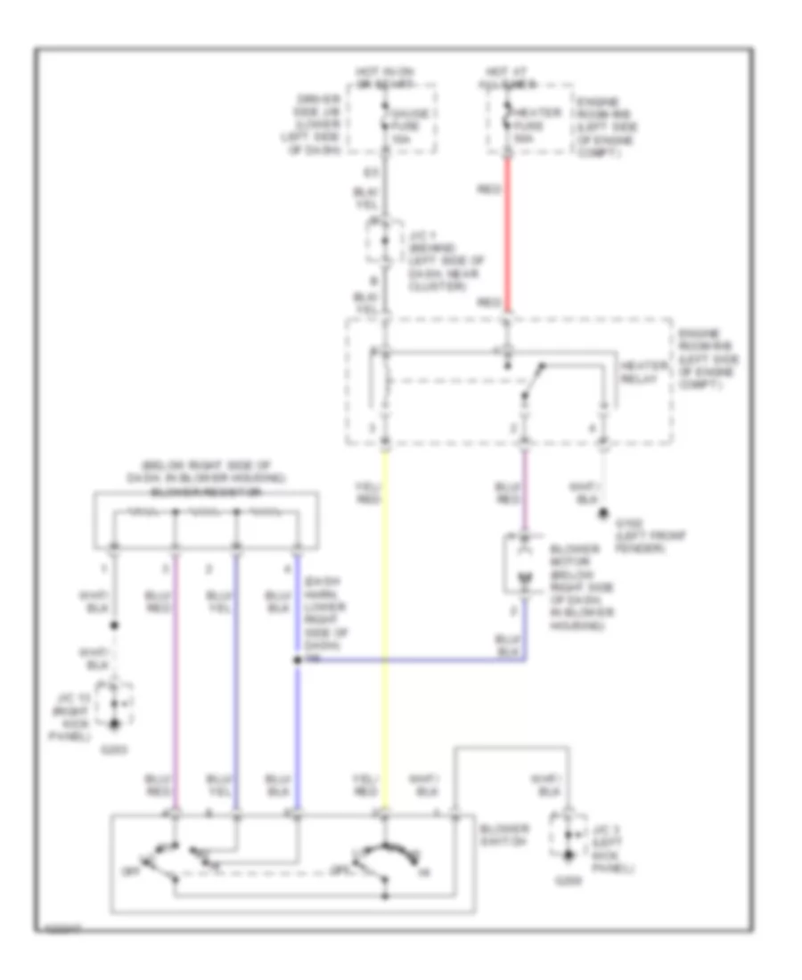
схема нагревателя для Toyota Tundra SR5 2000
схема нагревателя для Toyota Tundra SR5 2000 - Список элементов:
- (below right side of dash, in blower housing) blower resistor
- (dash harn, lower right side of dash) i16
- Blower motor (below right side of dash, in blower housing)
- Blower switch
- Driver side j/b (lower left side of dash)
- Engine room r/b (left side of engne compt)
- G102 (left front fender)
- G200
- G203
- Gauge fuse 10a
- Heater fuse 50a
- Heater relay
- Hot at all times
- Hot in on or start
- J/c 1 (behind left side of dash, near cluster)
- J/c 13 (right kick panel)
- J/c 3 (left kick panel)
- Off
- Red
Электросхема кондиционера с ручный управлением для Toyota Tundra SR5 2000
Электросхема кондиционера с ручный управлением для Toyota Tundra SR5 2000 - Список элементов:
- (3.4l) (4.7l)
- (4.7l)
- (below right side of dash, in blower housing) blower resistor
- (dash harn, upper right side of dash i16
- (dash harn, upper right side of dash) i4
- (engine room harn, in engine room r/b) e3
- (right of steering column) i2
- 4.7l
- A/c dual pressure switch (right front corner of engine compt)
- A/c fuse 10a
- A/c lock sensor
- A/c magnetic clutch
- A/c thermistor (behind right side of dash)
- A10
- A11
- A12
- A13
- A14
- A15
- A16
- A17
- A18
- A19
- A20
- A21
- A3 (4.7l)
- Ac+2
- Ac1 a/c
- Ac2
- Act
- Air inlet control servo (behind right side of dash)
- B1 (3.4l)
- B10
- B11
- B12
- B13
- B14
- B25
- Blower motor (below right side of dash, in blower housing)
- Blower switch
- Blower switch & defroster mode switch
- Calif 3.4l
- Combination meter
- Driver side j/b (lower left side of dash)
- E1 (engine room harn, in engine room r/b)
- Engine control module (behind right side of dash)
- Engine room r/b (left side of engne compt)
- Except calif 3.4l
- Frs
- G102 (left front fender)
- G200
- G200 (left kick panel)
- G203
- Gauge fuse 10a
- Gnd
- Heater fuse 50a
- Heater relay
- Hot at all times
- Hot in on or start
- Ig+
- Ig-
- Integraton control & panel
- J/c (left side of engine compt)
- J/c 12 (right side of dash)
- J/c 13 (right kick panel)
- J/c 3 (left kick panel)
- J/c 8 (right of steering column)
- Lock
- Mgc
- Off
- Power
- Rec
- Red
- Ssr-
- Tach
- Tachometer
СИСТЕМА КРУИЗКОНТРОЛЯ
3.4L
3.4L, Электросхема системы круизконтроля для Toyota Tundra SR5 2000
3.4L, Электросхема системы круизконтроля для Toyota Tundra SR5 2000 - Список элементов:
- (a/t)
- (a/t) (a/t) (a/t) (a/t) (a/t)
- (california)
- (except calif)
- (m/t)
- A11 e3
- A12
- A13
- A7 e3
- Acc fuse 15a
- B b b b b
- B24 e4
- B4 e4
- Cancel
- Ccs
- Cms
- Combination meter
- Control circuit
- Cruise control actuator w/ ecu (on right side of engine compt)
- Cruise control clutch switch (under left side of dash)
- Cruise control ind
- Cruise control switch (combination switch)
- D17 e6
- D8 e6
- Data link connector 1 (left side of engine intake manifold)
- Diode (a/t) (behind left side of dash)
- Drive position switch (park/neutral position switch) (on transmission)
- Driver side j/b (lower left end of dash)
- Ect
- Ecu-ig fuse 5a
- Engine control module (behind right side of dash)
- G11
- G13
- G200
- G200 (left kick panel)
- G203
- Gauge fuse 10a
- Gnd
- Gnd 1
- Hot at all times
- Hot in on & acc
- Hot in on & start
- I4 (dash harn, right end of dash)
- Idl
- Idlo
- J/c 12 (behind top end of dash)
- J/c 13 (right kick panel)
- J/c 3 (left kick panel)
- J/c 5 (behind left side of dash)
- J/c 7 (behind left side of dash)
- J/c 8 (behind left side of dash)
- J/c 8 j/c 8 j/c 8 j/c 8 j/c 8 behind left behind left behind left behind left behind left side of dash) side of dash) side of dash) side of dash) side of dash)
- J/c 9 behind left side of dash)
- Main
- Od1
- Op3
- Resume/ accel
- Set/ coast
- Spd
- Stop fuse 15a
- Stop- light switch (on braket, above brake pedal)
- Stp-
- Vehicle speed sensor (combination meter)
4.7L
4.7L, Электросхема системы круизконтроля для Toyota Tundra SR5 2000
4.7L, Электросхема системы круизконтроля для Toyota Tundra SR5 2000 - Список элементов:
- +b1
- +bm
- A10
- A12
- A13
- A16
- A19
- Acc fuse 15a
- Accel position sensor (on top front of engine)
- B15
- B19
- B23
- B24
- Batt
- Braided
- C c
- C11
- C13
- Cancel
- Ccs
- Cl+
- Cl-
- Cms
- Combination meter
- Cruise
- Cruise control switch (combination switch)
- Cruise ind
- D position switch (park/neutral position switch) (on transmission)
- D13
- D17
- D18
- D20
- D21
- Diode (a/t) (behind combination meter)
- Driver side j/b (lower left end of dash)
- E01
- E02
- E03
- E21
- E24
- E29
- E30
- E31
- Efi 1 fuse 15a
- Efi efi efi efi relay relay relay relay
- Engine control module (behind right side of dash)
- Engine engine engine room r/b room r/b room r/b (left side of (left side of (left side of engine compt) engine compt) engine compt)
- Etcs fuse 15a
- F11
- G102 (left front fender)
- G11
- G114 (left rear of engine)
- G131 (on intake manifold)
- G200 (left kick panel)
- Gauge fuse 10a
- Ge01
- Hot at all times
- Hot at all times hot at all times hot at all times hot at all times
- Hot in acc & on
- Hot in on or start
- I10 (engine harn, right side of dash at firewall)
- I5 (dash harn, right side of dash)
- I7 (engine harn, right side of dash, at firewall)
- Ign fuse 5a
- Igsw
- J/c 1 (on left side of engine compt)
- J/c 12 (behind upper right side of dash)
- J/c 7 (behind upper left side of dash)
- J/c 8 (behind upper left side of dash)
- J/c 9 (behind upper left side of dash)
- Me01
- Mrel
- Red
- Res/ acc
- Set/ coast
- Spd
- Speedo- meter
- St1-
- Stop stop stop fuse fuse fuse 15a 15a 15a
- Stoplight switch (on bracket, above brake pedal)
- Stp
- Throttle control motor (on top left front of engine)
- Throttle position sensor (on throttle body assembly)
- Vehicle speed sensor (combination meter) (on left side of transmission)
- Vpa
- Vpa2
- Vta
- Vta2
- W/ remote control mirror w/o remote control mirror
СИСТЕМА ПЕРЕДАЧИ ДАННЫХ
Электросхема компьютерной линии передачи данных CAN для Toyota Tundra SR5 2000
Электросхема компьютерной линии передачи данных CAN для Toyota Tundra SR5 2000 - Список элементов:
- (3.4l) i14
- (behind center of dash) j/c 5
- (left side of engine) (3.4l) g112
- Abs actuator with ecu (right rear of engine compt)
- Bat
- Center air bag sensor assembly (below center of dash)
- Cruise control actuator/ecu (3.4l only) (right side of engine compt)
- Data link connector 1 (left side of engine)
- Data link connector 3 (below left center of dash)
- Efi relay
- Engine control module (behind right side of dash)
- Engine controls sysytem
- Engine room r/b (left side of engine compt)
- G114 (4.7l) (left rear of engine)
- G120 (4.7l) (right side of engine)
- G131 (left intake manifold)
- G203
- Hot at all times
- I5 (dash harn, right side of dash)
- I7 (engine harn, right rear of engine compt)
- I9 (4.7l)
- Igniter (3.4l only) (right side of engine compt)
- Instrument cluster (3.4l only)
- J/c 1 (left side of engine compt)
- J/c 12 (behind right side of dash)
- J/c 13 (right kick panel)
- Obd fuse 7.5a
- Op3
- Sil
- Te1
СИСТЕМА УПРАВЛЕНИЯ ДВИГАТЕЛЯ
3.4L
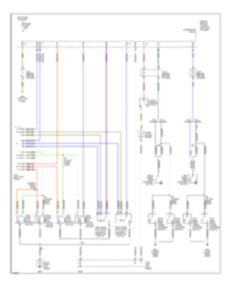
3.4L, Электросхема системы управления двигателя Калифорния (1 из 3) для Toyota Tundra SR5 2000
3.4L, Электросхема системы управления двигателя Калифорния (1 из 3) для Toyota Tundra SR5 2000 - Список элементов:
- (behind left side of dash) driver side j/b
- (engine harn, right rear of engine compt)
- (right side of engine compt) igniter
- (right side of engine compt) noise filter
- (top right of engine)
- A/t oil temperature sensor (top of transmission)
- Acc
- Af1+
- Af1-
- Air fuel ratio sensor (bank 1, sensor 1) (on front of exhaust)
- Camshaft position sensor (right front of engine)
- Conn e5
- Conn e6
- Crankshaft position sensor (left front of engine)
- E01
- E02
- E03
- E05
- E2g
- Engine control module (behind right side of dash)
- Engine coolant temperature sensor (top front of engine)
- Evp1
- Fuel injectors
- G131 (left intake manifold)
- Hot at all times
- Htaf1
- I11
- I12
- I13
- I14
- I15
- Igf
- Ignition coil 1
- Ignition coil 2
- Ignition coil 3
- Ignition switch
- Igt1
- Igt2
- Igt3
- Knk1
- Knk2
- Knock sensor 1 (right side of engine block)
- Knock sensor 2 (left side of engine block)
- Lock
- Mass airflow meter (on air intake)
- Nca
- Ne+
- Ne-
- Oil
- Pnk
- Power steering oil pressure switch (front of engine)
- Psw
- Red
- Rsc
- Rsd
- Run
- Sp2+
- Spd-
- Start
- Te1
- Tha
- Throttle position sensor (on throttle body)
- Thw
- Vta
3.4L, Электросхема системы управления двигателя Калифорния (2 из 3) для Toyota Tundra SR5 2000
3.4L, Электросхема системы управления двигателя Калифорния (2 из 3) для Toyota Tundra SR5 2000 - Список элементов:
- (engine harn, right rear of engine compt)
- (engine harn, right rear of engine compt) i12
- Automatic disconnecting differential actuator (rear of engine compt)
- Cruise control ecu (right side of engine)
- Data link connector (left side of engine)
- Driver side j/b (behind left side of dash)
- Electronically controlled transmission solenoid
- G131 (left intake manifold)
- G203
- Heated oxygen sensor (bank 1, sensor 2) (front of exhaust)
- Hot at all times
- I12
- I14
- Idle air control valve (top right side of engine)
- J/c 10 (behind center of dash)
- J/c 12 (behind right side of dash)
- J/c 12 (w/ cruise control) (behind right side of dash)
- J/c 13 (right kick panel)
- J/c 9 (behind center of dash)
- Nca
- Red
- Stop fuse 15a
- Stoplight switch (on bracket, above brake pedal)
- Transfer detection switch (l4) (transfer case)
- Transfer detection switch (neutral) (transfer case)
- Vapor pressure sensor (left rear of engine compt)
- Vehicle speed sensor (a/t) (on trans)
- Vsv (evap) (rear of engine)
3.4L, Электросхема системы управления двигателя Калифорния (3 из 3) для Toyota Tundra SR5 2000
3.4L, Электросхема системы управления двигателя Калифорния (3 из 3) для Toyota Tundra SR5 2000 - Список элементов:
- (center of dash) diode
- (center of left front fender) g100
- 11f
- 11g
- 13a
- 15b
- 4wd
- A pnk
- A/c system
- A/t
- A/t indicator light switch
- A/t oil temp
- Ac1
- Acc fuse 15a
- Act
- Batt
- C/opn relay
- Combination meter
- Conn e3
- Conn e4
- Control unit
- Data link connector (center of dash)
- Driver side j/b
- Driver side j/b (behind left side of dash)
- Efi 1 fuse 15a
- Efi relay
- Engine control module (behind right side of dash)
- Engine room r/b (left side of engine compt)
- Fuel pump (in fuel tank)
- G131 (left intake manifold)
- G200
- G203 (right kick panel)
- Gauge fuse 10a
- Hot at all times
- Hot in run hot in run hot in run or acc
- Hot in run or start
- Hot in start
- Hts hts
- Idlo idlo
- Ig+
- Ign fuse 5a
- Igsw
- J/c
- J/c 1 (left side of engine compt)
- J/c 11 (right side of dash)
- J/c 3 (left kick panel)
- J/c 5 (behind center of dash)
- J/c 6 (behind center of dash)
- J/c 7 (behind center of dash)
- M/t
- Malf ind lamp
- Mrel
- Nca
- Nsw
- O/d main switch (center of dash)
- O/d off ind
- Od1
- Od2
- Oilw
- Oxs
- Park/neutral position switch (or) clutch start switch
- Pnk
- Ptnk
- Red
- Sil
- Sp1
- Sta
- Sta fuse 5a
- Stp
- Tfn
- Tpc
- Vehicle speed sensor (on trans)
- Vsv (vapor pressure sensor) (left rear of engine compt)
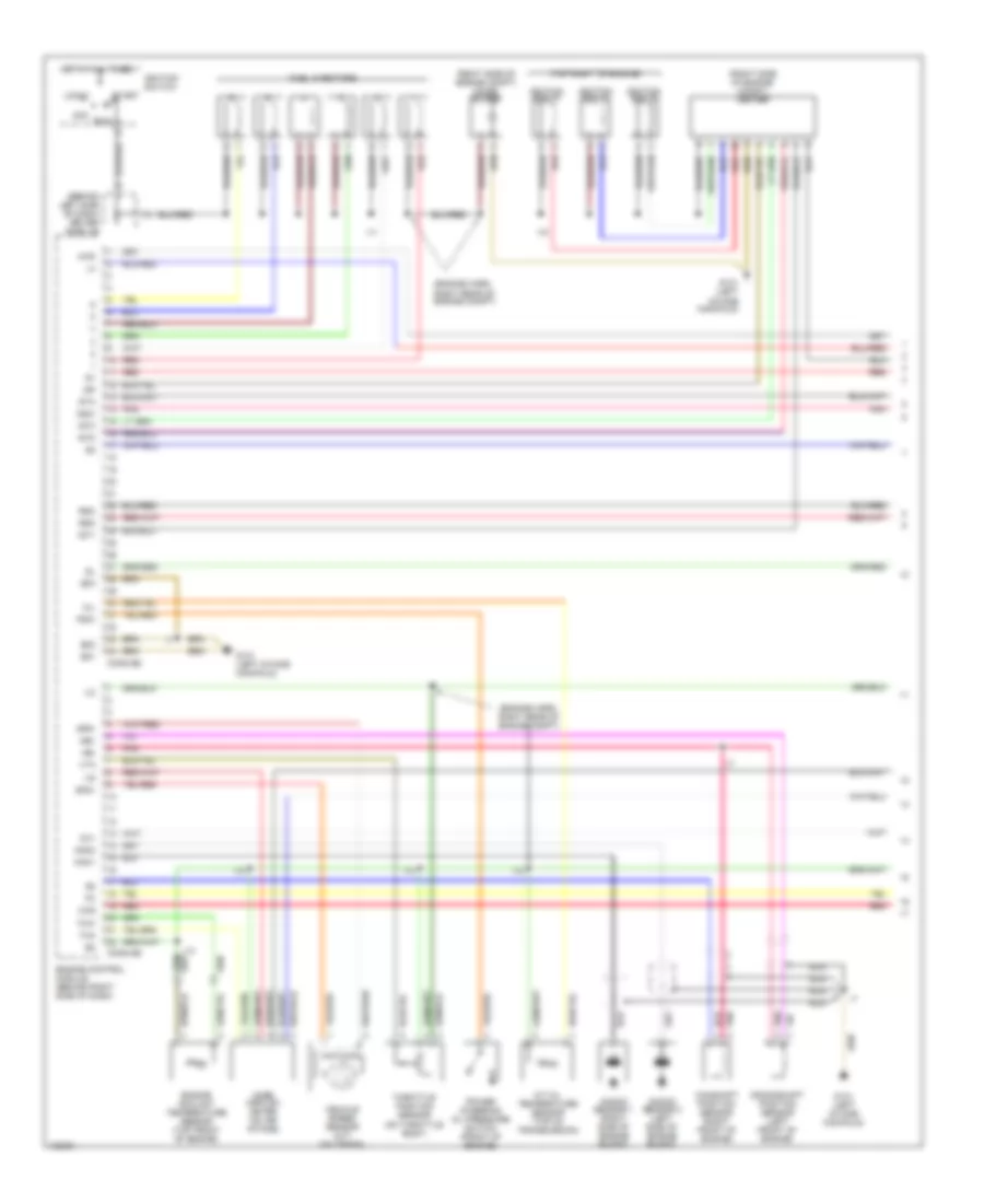
3.4L, Электросхема системы управления двигателя кроме Калифорнии (1 из 3) для Toyota Tundra SR5 2000
3.4L, Электросхема системы управления двигателя кроме Калифорнии (1 из 3) для Toyota Tundra SR5 2000 - Список элементов:
- (behind left side of dash) driver side j/b
- (engine harn, right rear of engine compt)
- (right side of engine compt) igniter
- (right side of engine compt) noise filter
- (top right of engine)
- 4wd
- A/t oil temperature sensor (top of transmission)
- Acc
- Camshaft position sensor (right front of engine)
- Conn e5
- Conn e6
- Crankshaft position sensor (left front of engine)
- E01
- E02
- E03
- Engine control module (behind right side of dash)
- Engine coolant temperature sensor (top front of engine)
- Fuel injectors
- G131 (left intake manifold)
- Hot at all times
- I11
- I13
- I15
- Igf
- Ignition coil 1
- Ignition coil 2
- Ignition coil 3
- Ignition switch
- Igt1
- Igt2
- Igt3
- Knk1
- Knk2
- Knock sensor 1 (right side of engine block)
- Knock sensor 2 (left side of engine block)
- Lock
- Mass airflow meter (on air intake)
- Nca
- Ne+
- Ne-
- Nsw
- Oil
- Ox1
- Oxs
- Pnk
- Power steering oil pressure switch (front of engine)
- Psw
- Red
- Rsc
- Rso
- Run
- Sp2+
- Spd-
- Sta
- Start
- Tha
- Throttle position sensor (on throttle body)
- Thw
- Vehicle speed sensor (a/t) (on trans)
- Vta
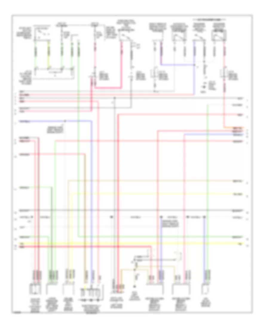
3.4L, Электросхема системы управления двигателя кроме Калифорнии (2 из 3) для Toyota Tundra SR5 2000
3.4L, Электросхема системы управления двигателя кроме Калифорнии (2 из 3) для Toyota Tundra SR5 2000 - Список элементов:
- (engine harn, right rear of engine compt)
- (on transfer case)
- (right rear of engine compt) abs actuator with ecu
- A pnk
- A/t
- Automatic disconnecting differential actuator
- Cruise control ecu (right side of engine)
- Data link connector (left side of engine)
- Driver side j/b (behind left side of dash)
- Electronically controlled transmission solenoid
- G131 (left intake manifold)
- G203
- Heated oxygen sensor (bank 1, sensor 1) (front of exhaust)
- Heated oxygen sensor (bank 1, sensor 2) (front of exhaust)
- Hot at all times
- Hot in start
- I12
- I14
- I7 (engine harn, right rear of engine compt)
- Idle air control valve (top right side of engine)
- J/c 10 (behind center of dash)
- J/c 12 (w/ cruise control) (behind right side of dash)
- J/c 13 (right kick panel)
- J/c 6 (behind center of dash)
- J/c 7 (behind center of dash)
- J/c 9 (behind center of dash)
- M/t
- Nca
- Park/neutral position switch (or) clutch start switch
- Pnk
- Red
- Sta fuse 5a
- Stop fuse 15a
- Stoplight switch (on bracket, above brake pedal)
- Transfer detection switch (l4)
- Transfer detection switch (neutral)
- Vapor pressure sensor (left rear of engine compt)
- Vsv (evap) (rear of engine)
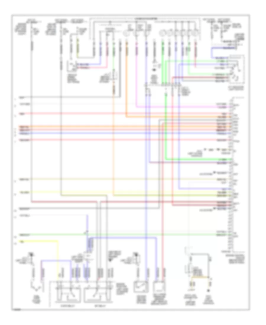
3.4L, Электросхема системы управления двигателя кроме Калифорнии (3 из 3) для Toyota Tundra SR5 2000
3.4L, Электросхема системы управления двигателя кроме Калифорнии (3 из 3) для Toyota Tundra SR5 2000 - Список элементов:
- (center of dash) diode
- (center of left front fender) g100
- 11f
- 11g
- 13a
- 15b
- A/c system
- A/t indicator light switch
- A/t oil temp
- Ac1
- Acc fuse 15a
- Act
- Batt
- C/opn relay
- Combination meter
- Conn e3
- Conn e4
- Control unit
- Data link connector (center of dash)
- Driver side j/b
- Driver side j/b (behind left side of dash)
- E2g
- Efi 1 fuse 15a
- Efi relay
- Engine control module (behind right side of dash)
- Engine room r/b (left side of engine compt)
- Evp1
- Fuel pump (in fuel tank)
- G131 (left intake manifold)
- G200
- G203 (right kick panel)
- Gauge fuse 10a
- Hot at all times
- Hot in run or acc
- Hot in run or start
- Hts hts
- I14
- Idlo idlo
- Ig+
- Ign fuse 5a
- J/c
- J/c 1 (left side of engine compt)
- J/c 11 (right side of dash)
- J/c 3 (left kick panel)
- J/c 5 (behind center of dash)
- J/c 7 (behind center of dash)
- Malf ind lamp
- Nca
- O/d main switch (center of dash)
- O/d off ind
- Od1
- Od2
- Oilw
- Ptnk
- Red
- Sil
- Sp1
- Stp
- Te1
- Tfn
- Tpc
- Vehicle speed sensor (on trans)
- Vsv (vapor pressure sensor) (left rear of engine compt)
4.7L
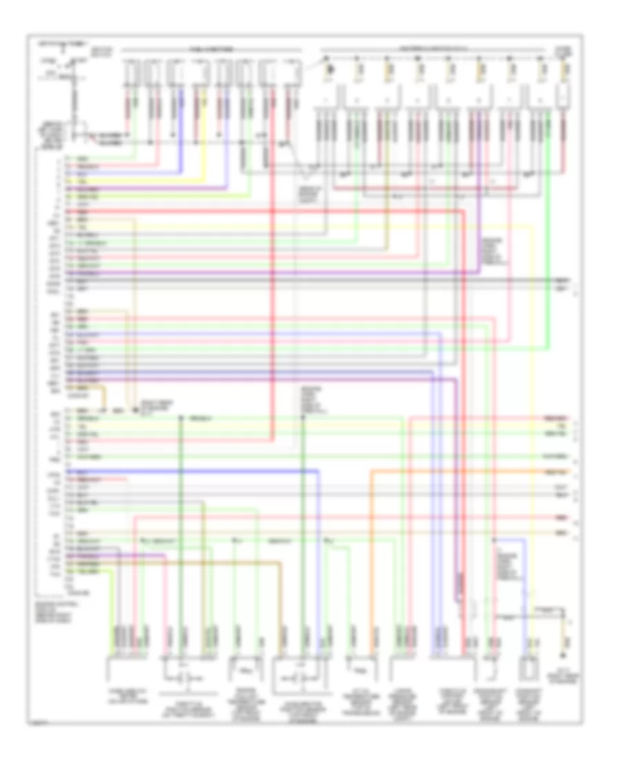
4.7L, Электросхема системы управления двигателя (1 из 3) для Toyota Tundra SR5 2000
4.7L, Электросхема системы управления двигателя (1 из 3) для Toyota Tundra SR5 2000 - Список элементов:
- (behind left side of dash) driver side j/b
- (engine harn, right side of firewall)
- (engine harn, right side of firewall) i7
- (rear of engine compt)
- (right rear of engine) g117
- A/t oil temperature sensor (top of transmission)
- Acc
- Accelerator position sensor (top front of engine)
- Camshaft position sensor (left front of engine)
- Cl+
- Cl-
- Conn e6
- Conn e7
- Crankshaft position sensor (left front of engine)
- E01
- E02
- E03
- Engine control module (behind right side of dash)
- Engine coolant temperature sensor (top front of engine)
- Evg
- Fuel injectors
- G117 (right rear of engine)
- Ge01
- Hot at all times
- Htl
- Htr
- I7 (engine harn, right side of firewall)
- Igf1
- Igf2
- Igniters & ignition coils
- Ignition switch
- Igt1
- Igt2
- Igt3
- Igt4
- Igt5
- Igt6
- Igt7
- Igt8
- Knkl
- Knkr
- Lock
- Mass airflow meter (on air intake)
- Me01
- Nca
- Ne+
- Ne-
- Noise filter
- Oxl1
- Oxr1
- Pnk
- Prg
- Red
- Run
- Start
- Tha
- Throttle control motor (left front of engine)
- Throttle position sensor (on throttle body)
- Thw
- Vapor pressure sensor (left rear of engine compt)
- Vpa
- Vpa2
- Vta
- Vta2
4.7L, Электросхема системы управления двигателя (2 из 3) для Toyota Tundra SR5 2000
4.7L, Электросхема системы управления двигателя (2 из 3) для Toyota Tundra SR5 2000 - Список элементов:
- (engine harn, right side of firewall)
- (left kick panel) j/c 3
- (on bracket, above brake pedal) stoplight switch
- 11g
- 13a
- 15b
- A/t indicator light switch (integral to park/neutral position switch) (on transaxle)
- A/t oil temp
- Acc fuse 15a
- C j/c 12 (right side of dash)
- Combination meter
- Control unit
- Diode (a/t) (center of dash)
- Driver side j/b
- Driver side j/b (behind left side of dash)
- Fuel pump (in fuel tank)
- Fuel pump resistor (left side of engine compt)
- G116 (left side of firewall)
- G117 (right rear of engine)
- G200
- G203 (right kick panel)
- Gauge fuse 10a
- Heated oxygen sensor (bank 1 sensor 1) (on exhaust manifold, left side of engine)
- Heated oxygen sensor (bank 1 sensor 2) (on exhaust pipe, left underside of vehicle)
- Heated oxygen sensor (bank 2 sensor 1) (on exhaust manifold, right side of engine)
- Heated oxygen sensor (bank 2 sensor 2) (on exhaust pipe, right underside of vehicle)
- Hot at all times
- Hot in run or acc
- Hot in run or start
- I10
- Ig+
- Integration relay
- J/c
- J/c 10 (behind center of dash)
- J/c 11 (right side of dash)
- J/c 6 (center of dash)
- J/c 7 (behind center of dash)
- J/c 8 (center of dash)
- Knock sensor 1 (left side of engine block)
- Knock sensor 2 (right side of engine block)
- Malf ind lamp
- Nca
- O/d main switch (center of dash)
- O/d off ind
- Red
- Stop fuse 15a
- Tail fuse 15a
- Vehicle speed sensor (on trans)
- Vsv (evap) (top left side of engine)
4.7L, Электросхема системы управления двигателя (3 из 3) для Toyota Tundra SR5 2000
4.7L, Электросхема системы управления двигателя (3 из 3) для Toyota Tundra SR5 2000 - Список элементов:
- (center of left front fender) g100
- (left rear of engine compt) vsv (vapor pressure sensor
- (left side of trans) o/d direct clutch speed sensor
- (left side of trans) vehicle speed sensor
- +b1
- +bm
- 11f
- A pnk
- A/c
- A/c system
- Act
- Batt
- C/opn relay
- Ccs
- Cms
- Conn e3
- Conn e4
- Conn e5
- Cruise control
- D red
- Data link connector (center of dash)
- Data link connector (left top of engine)
- Detection switch (l4) (on transfer case)
- Driver side j/b (behind left side of dash)
- Efi 1 fuse 15a
- Efi 2 fuse 15a
- Efi relay
- Electronically controlled transmission solenoid (in transmission)
- Els
- Engine control module (behind right side of dash)
- Engine room r/b
- Engine room r/b (left side of engine compt)
- Etcs fuse 15a
- Fpr
- Fuel pump relay
- G116 (left side of firewall)
- G117 (right rear of engine)
- G203
- Hot at all times
- Hot in run or start
- Hot in start
- Htl2
- Htr2
- Ign fuse 5a
- Igsw
- J/c 1 (left side of engine compt)
- J/c 12 (right side of dash)
- J/c 13 (right kick panel)
- J/c 5 (behind center of dash)
- J/c 6 (behind center of dash)
- J/c 7 (behind center of dash)
- Mrel
- Nco+
- Nco-
- Nsw
- Od2
- Oil
- Oilw
- Oxl2
- Oxr2
- Park/neutral position switch (left side of trans)
- Pnk
- Ptnk
- Red
- Sil
- Slt
- Slt+
- Slt-
- Sp2+
- Sp2-
- Spd
- St1-
- Sta
- Sta fuse 5a
- Stp
- Tach
- Tpc
Система Фар
Электросхема фар, С DRL для Toyota Tundra SR5 2000
Электросхема фар, С DRL для Toyota Tundra SR5 2000 - Список элементов:
- (engine harn, in engine room r/b) e3
- (left front fender) g102
- A/t
- Brake fluid level warning switch (on brake fluid reservoir)
- C12
- Combination meter
- Combinaton switch
- Control switch
- Daytime running light relay
- Daytime running light relay (main) (behind center of dash)
- Daytime running light resistor (on left front side of engine compartment)
- Dimmer relay
- Dimmer switch
- Diode 1 (drl) (behind top left side of dash)
- Diode 2 (drl) (right of steering column)
- Dome fuse 15a
- Driver side j/b (lower left side of dash)
- Drl fuse 7.5a
- Engine room r/b (left side of engine compt)
- Flash
- Fog relay
- Fog- light switch
- Fr fog fuse 20a
- G200
- G203
- Gauge fuse 10a
- Head
- Head relay
- High
- High beam indicator
- Hot at all times
- Hot in on or start
- I2 (upper left side of dash, right of steering column)
- Integration relay
- J/c 13 (right kick panel)
- J/c 2 (left side of engine compt)
- J/c 3 (left kick panel)
- J/c 7 (right of steering column)
- J/c 8 (right of steering column)
- J/c 9 (right of steering column)
- Left front foglight
- Left head- light
- Left hi head fuse 10a
- Left lo head fuse 10a
- Light
- Low
- M/t
- Off
- Parking brake switch (on base of park brake lever)
- Pnk
- Red
- Right front foglight
- Right head- light
- Right hi head fuse 10a
- Right lo head fuse 10a
- Starting/ charging system
- Tail
Электросхема фар, без DRL для Toyota Tundra SR5 2000
Электросхема фар, без DRL для Toyota Tundra SR5 2000 - Список элементов:
- (engine harn, in engine room r/b) e3
- (left front fender) g102
- C12
- Combination meter
- Combination switch
- Dimmer switch
- Driver side j/b (lower left side of dash)
- Engine room r/b (left side of engine compt)
- Flash
- Fog relay
- Foglight switch
- Fr fog fuse
- G200
- G203
- Head
- Head relay
- High
- High beam indicator
- Hot at all times
- I2 (upper left side of dash, right of steering column)
- Integration relay
- J/c 13 (right kick panel)
- J/c 2 (left side of engine compt)
- J/c 3 (left kick panel)
- J/c 6 (right of steering column)
- Left front foglight
- Left head fuse 10a
- Left headlight
- Light control switch
- Low
- Off
- Pnk
- Red
- Right front foglight
- Right head fuse 10a
- Right headlight
- Tail
СИСТЕМЫ СИДЕНИЙ
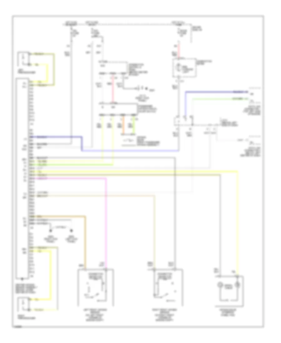
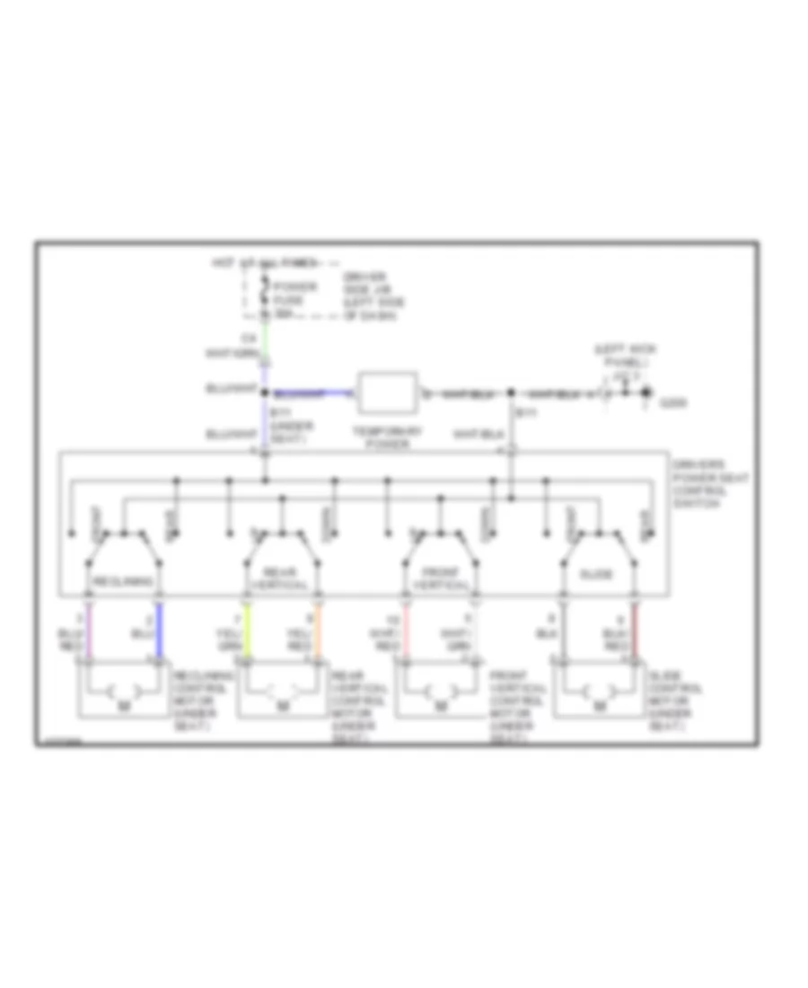
Электросхема привода водительского сиденья для Toyota Tundra SR5 2000
Электросхема привода водительского сиденья для Toyota Tundra SR5 2000 - Список элементов:
- (left kick panel) j/c 3
- B11
- Down
- Driver side j/b (left side of dash)
- Driver's power seat control switch
- Front
- Front vertical
- Front vertical control motor (under seat)
- G200
- Hot at all times
- Power fuse 30a
- Rear
- Rear vertical
- Rear vertical control motor (under seat)
- Reclining
- Reclining control motor (under seat)
- Slide
- Slide control motor (under seat)
- Temporary power
Стартер Генератор
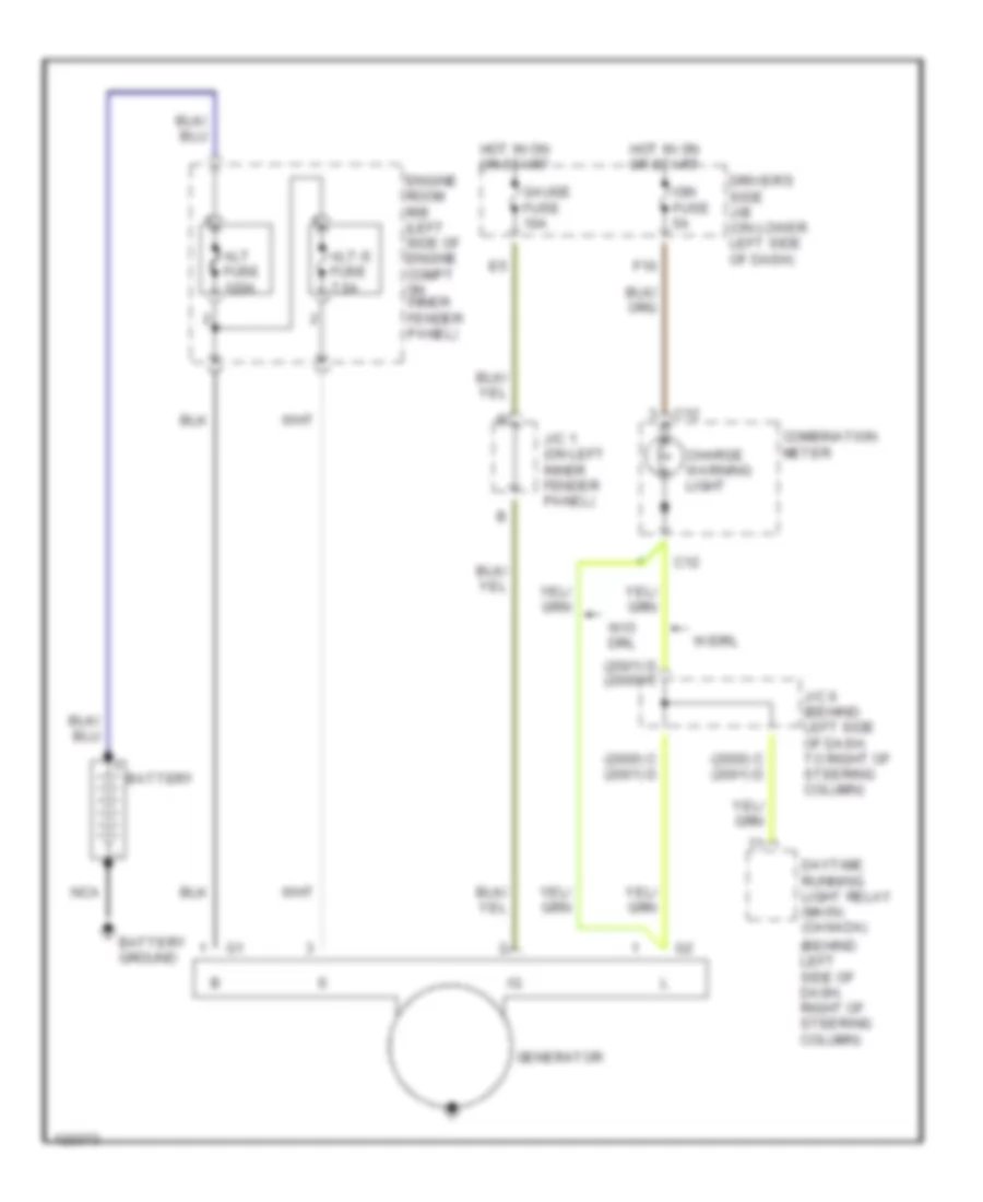
Электросхема Генератора для Toyota Tundra SR5 2000
Электросхема Генератора для Toyota Tundra SR5 2000 - Список элементов:
- (2000) c (2001) d
- (2001) d (2000) c
- (behind left side of dash, right of steering column)
- Alt fuse 120a
- Alt-s fuse 7.5a
- Battery
- Battery ground
- C12
- Charge warning light
- Combination meter
- Daytime running light relay (main) (canada)
- Driver's side j/b (on lower left side of dash)
- Engine room r/b (left side of engine compt on inner fender panel)
- F10
- Gauge fuse 10a
- Generator
- Hot in on or start
- Ign fuse 5a
- J/c 1 (on left inner fender panel)
- J/c 6 (behind left side of dash, to right of steering column)
- Nca
- W/drl
- W/o drl
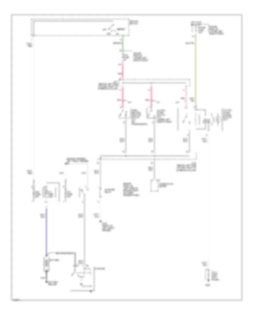
Электросхема стартера для Toyota Tundra SR5 2000
Электросхема стартера для Toyota Tundra SR5 2000 - Список элементов:
- (engine harness, left front fender) e2
- A/t
- Acc
- Alt fuse 120a
- Am1 fuse 40a
- Am2 fuse 30a
- Battery
- Battery ground
- C13
- Clutch start cancel switch (m/t)
- Clutch start switch (m/t) (under left side of dash)
- Combination meter
- Driver side j/b (lower left side of dash)
- Engine room j/b (left side of engine compt, on inner fender panel)
- G100 (front of left front fender)
- G200
- Gauge fuse 10a
- Hot in on or start
- Ignition switch
- J/c 3 (left kick panel)
- J/c 6 (behind left side of dash, right of steering column)
- J/c 7 (behind left side of dash, right of steering column)
- M/t
- Nca
- Off
- P/ n
- Park/ neutral position switch (a/t) (on transmission)
- Pnk
- Solid state
- Sta fuse 5a
- Start
- Starter
- Starter relay
Стеклоочистители и Стеклоомыватели Дворники
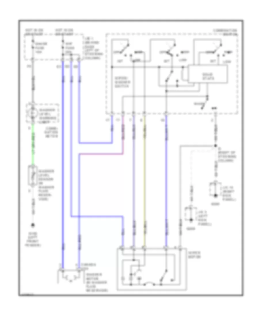
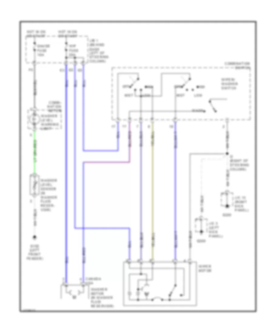
дворник/Шайба, С Неустойчивый для Toyota Tundra SR5 2000
дворник/Шайба, С Неустойчивый для Toyota Tundra SR5 2000 - Список элементов:
- Canada usa
- Combi- nation meter
- Combination switch
- G102 (left front fender)
- G200
- G203
- Gauge fuse 10a
- High
- Hot in on or start
- I2 (right of steering column)
- Int
- J/b 1 (behind dash left of steering column)
- J/c 13 (right kick panel)
- J/c 3 (left kick panel)
- Low
- Off
- Solid state
- Wash
- Washer level sensor (in washer fluid reser- voir)
- Washer level warning light
- Washer motor (in washer fluid reservoir)
- Wip fuse 20a
- Wiper motor
- Wiper/ washer switch
дворник/Шайба, без Неустойчивый для Toyota Tundra SR5 2000
дворник/Шайба, без Неустойчивый для Toyota Tundra SR5 2000 - Список элементов:
- Canada usa
- Combi- nation meter
- Combination switch
- G102 (left front fender)
- G200
- G203
- Gauge fuse 10a
- High
- Hot in on or start
- I2 (right of steering column)
- J/b 1 (behind dash left of steering column)
- J/c 13 (right kick panel)
- J/c 3 (left kick panel)
- Low
- Mist
- Off
- Wash
- Washer level sensor (in washer fluid reser- voir)
- Washer level warning light
- Washer motor (in washer fluid reservoir)
- Wip fuse 20a
- Wiper motor
- Wiper/ washer switch
ЦЕНТРАЛЬНЫЙ ЗАМОК
Электросхема центрального замка для Toyota Tundra SR5 2000
Электросхема центрального замка для Toyota Tundra SR5 2000 - Список элементов:
- (in right front door) b7
- B15
- B16
- B3 (in left front door)
- B6 (in right front door)
- B8 (in left rear door)
- B9 (in right rear door)
- Combi- nation meter
- Driver side j/b (lower left side of dash)
- G200
- G200 (left kick panel)
- G203
- G700 (in left rear door)
- G800 (in right rear door)
- Hot in run or start
- Integration relay
- J/c 10 (behind center of dash)
- J/c 13 (right kick panel)
- J/c 3 (left kick panel)
- J/c 4 (left kick panel)
- J/c 8 (behind center of dash)
- J/c 9 (behind center of dash)
- Left door key lock & unlk unlock switch
- Left door lock control unlk switch
- Left door lock motor & unlock detection switch
- Left front door courtesy switch
- Left rear door lower courtesy switch
- Left rear door upper courtesy switch
- Lock
- Power fuse 30a
- Right door key lock & unlk unlock switch
- Right door lock control unlk switch
- Right door lock motor & unlock detection switch
- Right front door courtesy switch
- Right rear door lower courtesy switch
- Right rear door upper courtesy switch
- Unlock warning switch
- W/ 2 doors
- W/ 4 doors

 Čeština
 Dansk
Dansk Deutsch
 Ελληνικά
 English
 Español
 Suomi
Suomi Français
 Français
 עברית
עברית Hrvatski
 Magyar
 Italiano
 日本語
日本語 한국어
한국어 Nederlands
 Polski
 Português
 Português
 Română
 Русский
 Slovenčina
 Slovenščina
 Svenska
 Türkçe
 中文 (中国)