ANTI-LOCK BRAKES
Anti-lock Brake Wiring Diagrams for Jaguar XJ8 1998
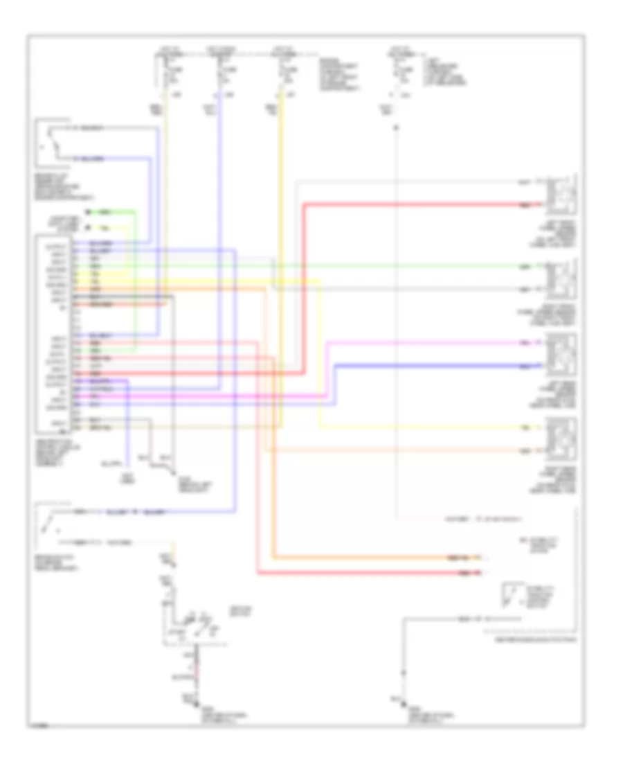
List of elements for Anti-lock Brake Wiring Diagrams for Jaguar XJ8 1998:
- (i) acc
- (ii) run
- (not used)
- Abs/traction control module (behind left headlight assembly)
- Brake fluid reservoir (brake booster enclosure in engine compartment)
- Brake switch (on brake pedal bracket)
- Ca1
- Center console switch pack
- Computer data lines system
- Data +
- Data -
- Engine compartment fuse box (in left front of engine compartment)
- Fuse 10a
- Fuse 30a
- Fuse 5a
- G106 (behind left headlight)
- G206 (center of dash, on firewall)
- Hot at all times
- Hot in run & start
- Ignition switch
- Input
- Left front wheel speed sensor (on left front wheel hub assy)
- Left heelboard fuse box (on left side of heelboard)
- Left rear wheel speed sensor (on rear axle, near wheel hub)
- Ls5
- Ls7
- Ls8
- Nca
- Off (0)
- Output
- Red
- Right front wheel speed sensor (on right front wheel hub assy)
- Right rear wheel speed sensor (on rear axle, near wheel hub)
- Sig gnd
- Stability/ traction control switch
- Stability/ traction state
- Start (iii)
 English