ANTI-THEFT
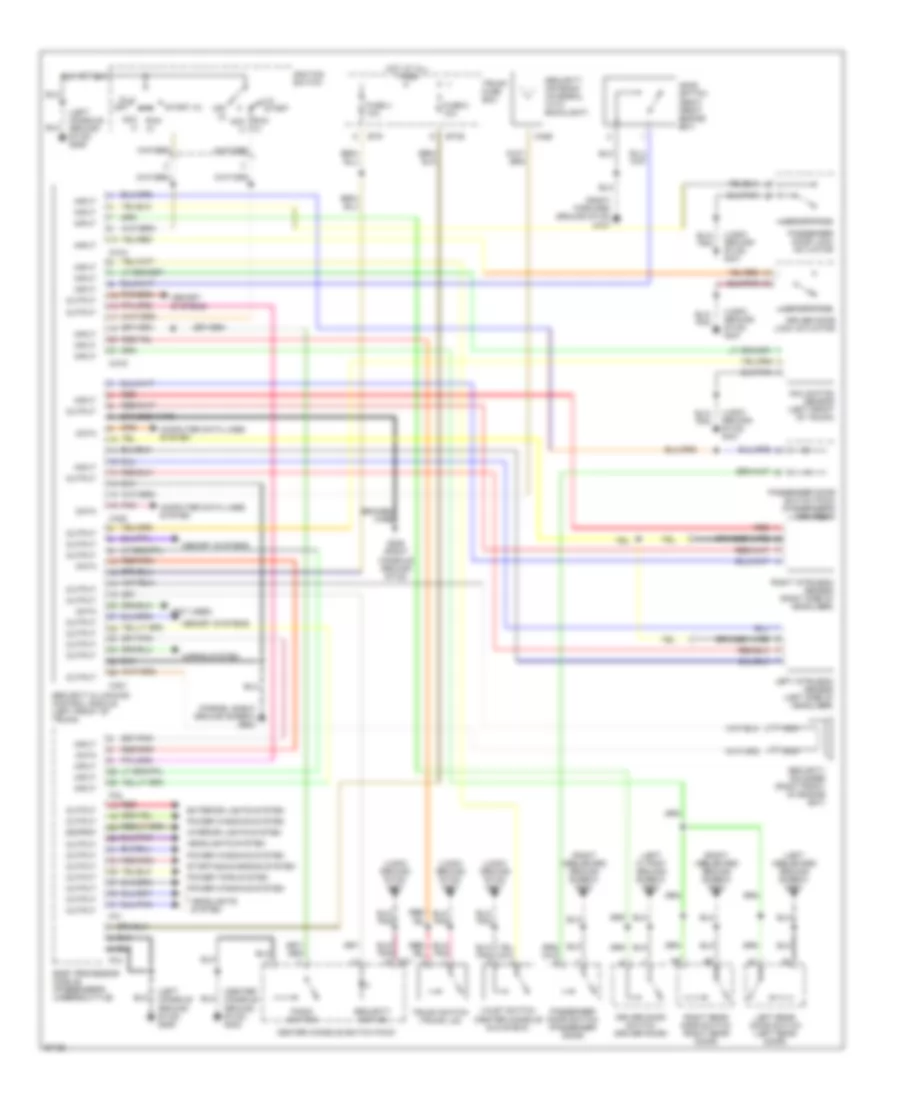
Anti-theft Wiring Diagram for Jaguar XJR 1997
List of elements for Anti-theft Wiring Diagram for Jaguar XJR 1997:
- (0) off
- (center console ground stud) g302
- (ii)
- (iii) start
- (left "a" post ground screw) g202
- (left console ground stud) g206
- (left heelboard ground screw) g304
- (logic ground stud) g401
- (not used)
- (parcel shelf ground screw) g904
- (right forward ground stud) g107
- (right heelboard ground screw) g303
- Acc (i)
- Body processor module (passenger's underscuttle)
- Braided wire
- Bt35
- Bt9
- Ca18
- Ca19
- Ca20
- Ca21
- Ca26
- Cc1
- Center console switch pack
- Computer data lines system
- Data
- Driver door lock actuator
- Driver door switch (driver door)
- Exterior lights system
- Fc1
- Fc2
- Fc3
- Fuse 4 10a
- Fuse 5 10a
- G206 (right console ground stud)
- Headlights system
- Hood switch (right front engine bay)
- Horns system
- Hot at all times
- Ignition switch
- Inclination sensor (left front of trunk)
- Input
- Interior lights system
- Left intrusion sensor (left side of headliner)
- Left rear door switch (left rear door)
- Lock status
- Memory systems
- Nca
- Off (0)
- Output
- Output output
- Panic switch
- Passenger door lock actuator
- Passenger door switch (passenger door)
- Passenger door switch pack (passenger's arm rest)
- Pnk
- Power tops system
- Power windows system
- Red
- Right intrusion sensor (right side of headliner)
- Right rear door switch (right rear door)
- Run (ii)
- Run acc (i)
- Security & locking control module (left front of trunk)
- Security active
- Security antenna (integral with backlight)
- Security sounder (right front of engine bay)
- Start (iii)
- Starting/charging system
- Trunk fuse box
- Trunk switch (trunk lid)
- Valet switch (center console glove box)
 English