CRUISE CONTROL
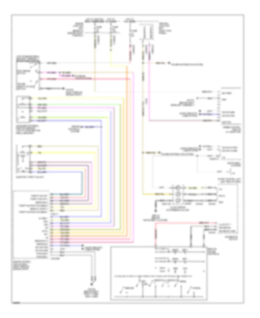
Cruise Control Wiring Diagram, without Adaptive Cruise Control for Jaguar XF Supercharged 2012
List of elements for Cruise Control Wiring Diagram, without Adaptive Cruise Control for Jaguar XF Supercharged 2012:
- (top of brake pedal bracket assembly) brake pedal switch
- 5v ref +
- Accelerator pedal position sensor (top of accelerator pedal bracket)
- Ap 5v
- Ap1
- Ap2
- Ap2-
- Battery
- Brake sw
- Brake sw 2
- C1bb01b
- C1e117
- C1e120b
- C23-d
- C2mc01a
- C2r115a
- C38po1g
- C3bp01d
- C3bp01e
- Can
- Cancel
- Central junction box (right kick panel)
- Clock spring (in steering column)
- Computer data lines system
- Cruise deactivation switch
- Cruise sig
- Cruise sw gnd
- Decel
- Electric throttle unit
- Engine control module (ecm) (right rear of engine compt)
- Engine controls system
- Engine junction box (beneath engine compt fuse box)
- Exterior lights system
- Foot brake switch
- Fuse 10a
- Fuse 5a
- G1d108 (behind right front wheel arch liner)
- G1d120 (right rear of engine compt)
- G1d131 (behind right headlight assembly)
- G2d115 (behind instrument cluster)
- Gnd
- Head+
- Head-
- Headway (+)
- Headway (-)
- Hot at all times
- Hot w/ ignition relay energized
- Hs can in pos
- Hs can pos
- Ice remote switch
- Ign in
- Ignition
- Illum out 1
- Instrument cluster
- Lin
- Power distribution system
- Pwr gnd 1
- Pwr gnd 2
- Remote cruise controls
- Res
- Resume
- Sa004
- Sens gnd 2
- Set+
- Set-
- Set/ accel
- Speed control module (w/ adaptive)
- Start control unit (left end of dash)
- Sw002
- Sw003
- Sw004
- Throttle mtr +
- Throttle mtr -
- Throttle position sens 1
- Throttle position sens 2
 English