ENGINE PERFORMANCE
5.0L
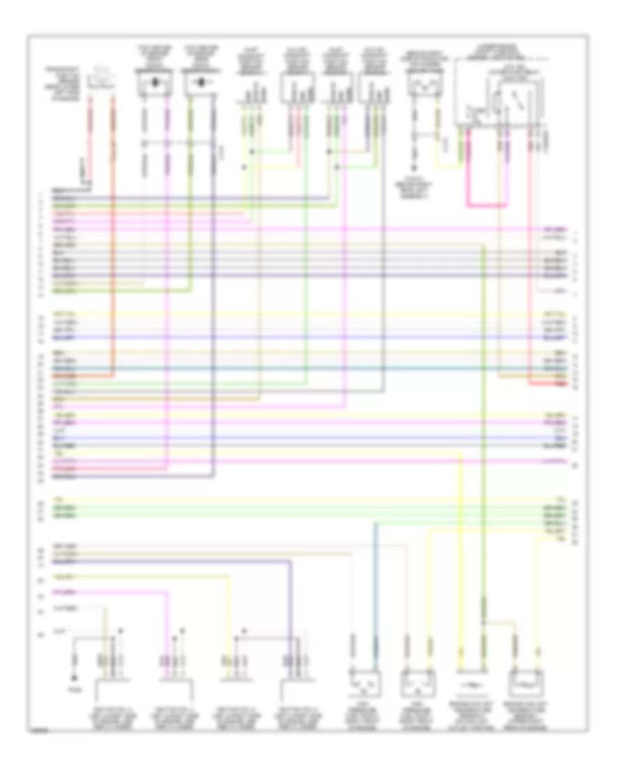
5.0L, Engine Performance Wiring Diagram (1 of 6) for Jaguar XF 2012

List of elements for 5.0L, Engine Performance Wiring Diagram (1 of 6) for Jaguar XF 2012:
- (on left & right fuel rail, one per cylinder) fuel injector 1
- (on left & right fuel rail, one per cylinder) fuel injector 2
- (on left & right fuel rail, one per cylinder) fuel injector 3
- (on left & right fuel rail, one per cylinder) fuel injector 4
- (on left & right fuel rail, one per cylinder) fuel injector 5
- (on left & right fuel rail, one per cylinder) fuel injector 6
- (on left & right fuel rail, one per cylinder) fuel injector 7
- (on left & right fuel rail, one per cylinder) fuel injector 8
- Air temp gnd
- C11-a
- C11-p
- C1e117
- Cam ex a
- Cam ex b
- Cam in a
- Cam in b
- Cam sen a gnd
- Cam sen b gnd
- Cam sen b sply
- Cam sens a
- Capacitor
- Coolant temp 2
- Crank sens
- Crank sens gnd
- Engine control module (ecm) (right rear of engine compt)
- Front knock sensor bank 2
- Fuel press sens
- Fuel pump 1
- Fuel pump 2
- Gref
- Htr ctrl
- Htr ctrl b
- Ignition coil 1 (left & right side of engine, one per cylinder)
- Ignition coil 3 (left & right side of engine, one per cylinder)
- Ignition coil 5 (left & right side of engine, one per cylinder)
- Ignition coil 7 (left & right side of engine, one per cylinder)
- Ignitor 1b
- Ignitor 2a
- Ignitor 2b
- Ignitor 3a
- Ignitor 3b
- Ignitor 4a
- Ignitor 4b
- Inj 1a commom
- Inj 1b commom
- Inj 2a
- Inj 2a commom
- Inj 2b
- Inj 2b common
- Inj 3a
- Inj 3b common
- Inj 4a
- Inj 4a common
- Inj 4b
- Inj 4b common
- Inlet air temp b
- Knock sens 1a
- Knock sens 1b
- Knock sens 2a
- Knock sens 2b
- Maf sens gnd a
- Map sens gnd
- P1080
- Rear knock sensor bank 2
- Sen gnd
- Sens gnd
- Sensor gnd
- Tmap sens
- Tps 5v feed
- Uhego a
- Uhego b
- Vref
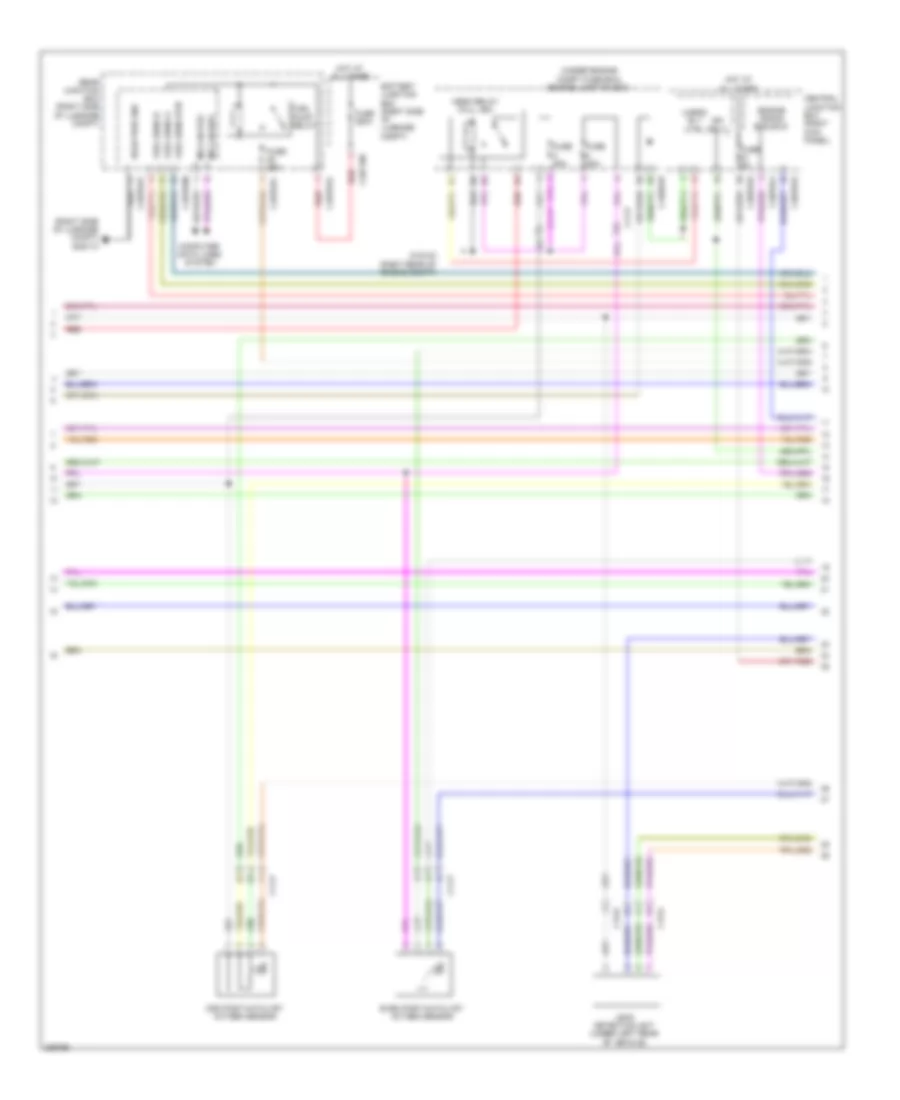
5.0L, Engine Performance Wiring Diagram (2 of 6) for Jaguar XF 2012
List of elements for 5.0L, Engine Performance Wiring Diagram (2 of 6) for Jaguar XF 2012:
- (5.0l sc) water pump relay (half iso)
- (behind right side of radiator) air charge coolant pump
- (top center of engine) front knock sensor bank 1
- (top center of engine) rear knock sensor bank 2
- (under engine compt fuse box) engine junction box
- C11-a
- C11-r
- C1bb01b
- Crankshaft position sensor (rear lower left side of engine)
- Engine coolant temperature sensor 1 (upper right rear of engine)
- Engine coolant temperature sensor 2 (on coolant outlet casting)
- Fuse 15a
- G1d131 (behind right headlight assembly)
- Gnd
- High pressure fuel pump 1 (right front of engine)
- High pressure fuel pump 2 (right front of engine)
- Ignition coil 2 (left & right side of engine, one per cylinder)
- Ignition coil 4 (left & right side of engine, one per cylinder)
- Ignition coil 6 (left & right side of engine, one per cylinder)
- Ignition coil 8 (left & right side of engine, one per cylinder)
- Inlet camshaft position sensor (bank 1)
- Inlet camshaft position sensor (bank 2)
- Nca
- Outlet camshaft position sensor (bank 1)
- Outlet camshaft position sensor (bank 2)
- Pi082
- Pwr 5v
- Red
- Sens
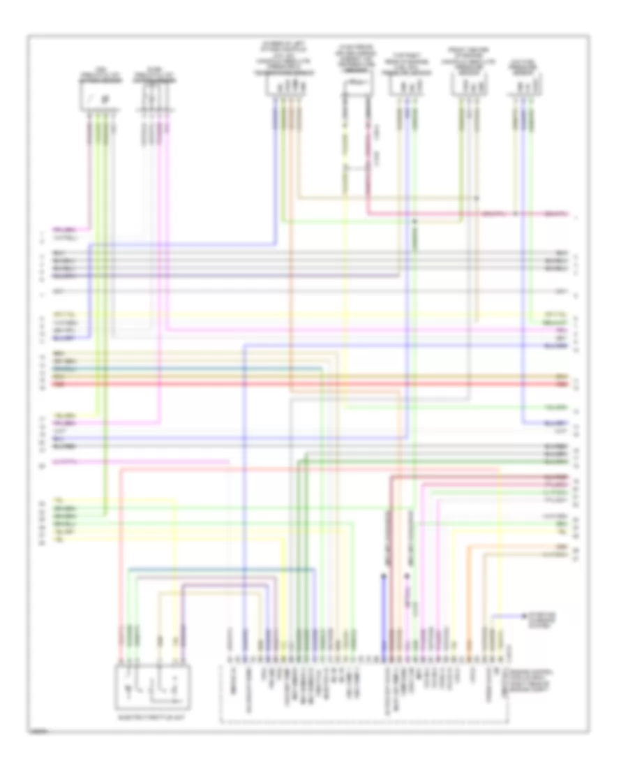
5.0L, Engine Performance Wiring Diagram (3 of 6) for Jaguar XF 2012
List of elements for 5.0L, Engine Performance Wiring Diagram (3 of 6) for Jaguar XF 2012:
- (front center of engine) manifold absolute pressure sensor
- (in exterior driver mirror) ambient air temperature sensor
- (in rear of left intake manifold) (5.0l sc) manifold absolute pressure & temperature sensor
- (info not available)
- (top right rear of engine) fuel rail pressure sensor
- +5v
- Active ext valve
- C11-p
- C13-e
- C1e117
- C3a-a
- Coolant temp
- Cps a
- Cps b
- E box fan
- Electric throttle unit
- Engine control module (ecm) (right rear of engine compt)
- Even pre-catalyst oxygen sensor
- Fuel pump 1
- Fuel pump 2
- Gnd
- Ignitor 1a
- Imtv
- Inj 1b
- Inj 3b
- Injector 1a
- Inlet air temp a
- Lin
- Low fuel pressure sensor
- Maf sensor a
- Maf sensor b
- Map sensor
- Odd pre-catalyst oxygen sensor
- Oil quality sens
- Purge valve
- Red
- Sig
- Starting/ charging system
- Temp
- Temp sens
- Throttle +
- Throttle -
- Tps gnd
- Tps1
- Tps2
- Vfs ex b
- Vfs in a
- Vfs in b
- Vfsex a
- Vout
- Vref
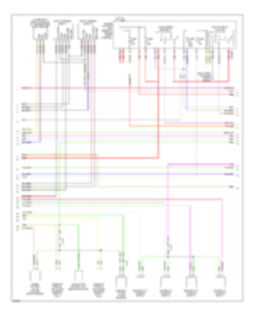
5.0L, Engine Performance Wiring Diagram (4 of 6) for Jaguar XF 2012
List of elements for 5.0L, Engine Performance Wiring Diagram (4 of 6) for Jaguar XF 2012:
- (lower right front of engine) oil temperature level sensor
- (right rear of engine compt) g1d123
- C11-a
- C11-p
- C1bb01b
- Camshaft profile switching solenoid (bank 1) (5.0l)
- Camshaft profile switching solenoid (bank 2) (5.0l)
- Cooling fan control unit (behind radiator)
- Engine junction box (beneath engine compt fuse box)
- Exhaust vvt solenoid (bank 1)
- Exhaust vvt solenoid (bank 2)
- Fuse 10a
- Fuse 15a
- Fuse 20a/ 15a
- Fuse 50a
- Gnd
- Gnf
- High current ems relay
- Hot at all times
- Iat gnd
- Iat output
- Ignition relay (half iso)
- Intake vvt solenoid (bank 1)
- Intake vvt solenoid (bank 2)
- Maf sens
- Maf/iat sensor (bank 1)
- Maf/iat sensor (bank 2)
- Manifold intake tuning solenoid
- Purge control valve (top left side of engine)
- Pwr
- Red
- Sig
- Vref
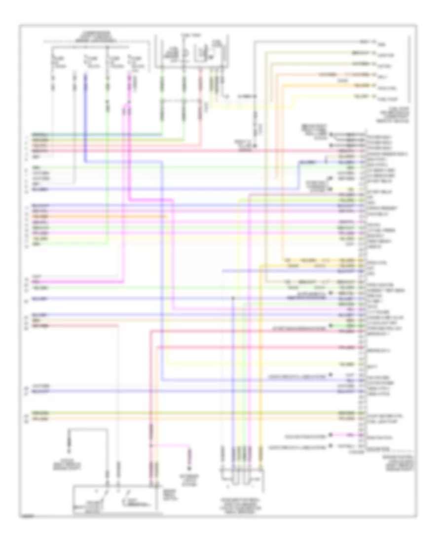
5.0L, Engine Performance Wiring Diagram (5 of 6) for Jaguar XF 2012
List of elements for 5.0L, Engine Performance Wiring Diagram (5 of 6) for Jaguar XF 2012:
- (right side of luggage compt) g4d173
- (under engine compt fuse box) engine junction box
- Battery junction box (right side of luggage compt)
- C11-p
- C13-a
- C13-d
- C1bb01b
- C3bp01e
- C3bp01g
- C3bp01j
- C4bf10b
- C4bp01a
- C4bp01c
- C4bp01g
- C4bp01m
- Central junction box (right kick panel)
- Computer data lines system
- Engine crank ems ewc
- Even post-catalyst oxygen sensor
- Fuel pump relay
- Fuel sens a
- Fuel sens b
- Fuel sens rtn
- Fuse 20a
- Fuse 250a
- Fuse 25a
- Fuse 5a
- G1d123 (right rear of engine compt)
- Hego relay (full iso)
- Hot at all times
- Ign sply
- Leak detection unit (under left rear of vehicle)
- Ms can pos
- Odd post-catalyst oxygen sensor
- Rear junction box (right side of luggage compt)
- Red
- Rsjb pwr gnd
- Uhego rly ctrl
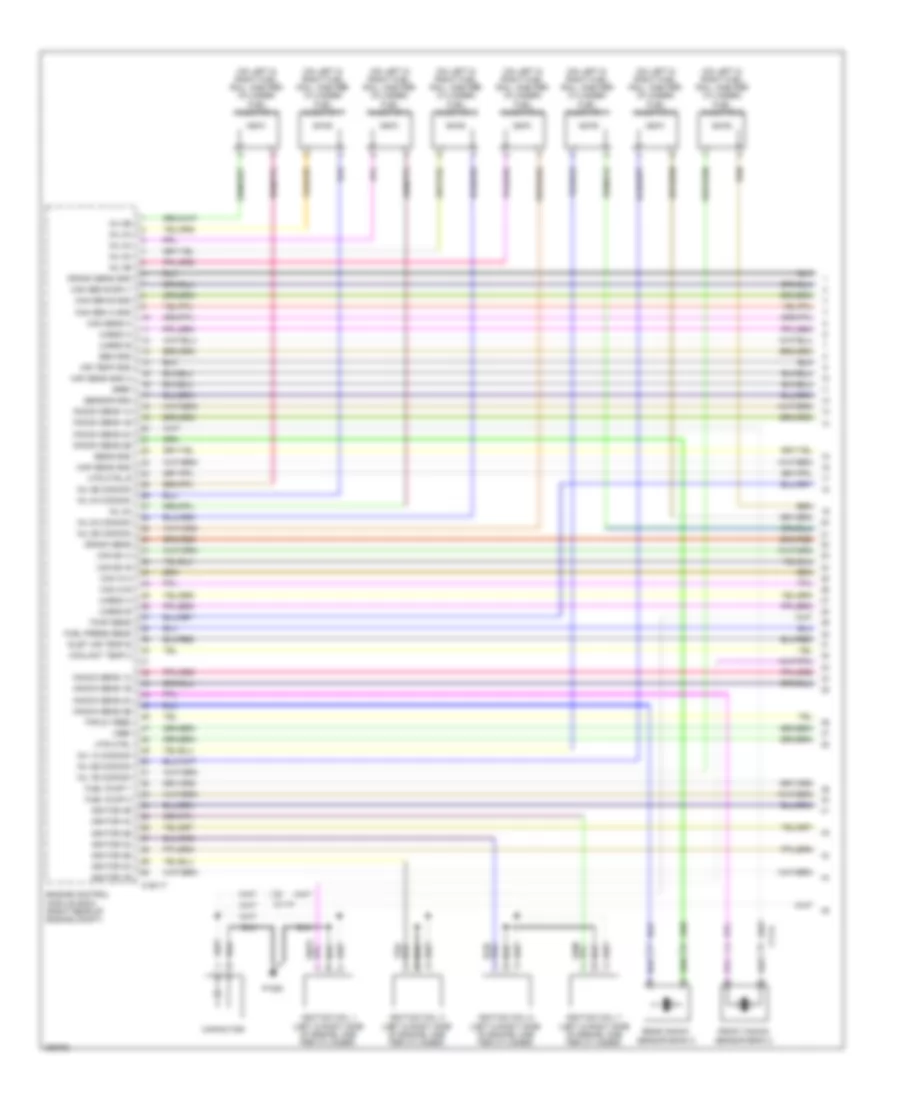
5.0L, Engine Performance Wiring Diagram (6 of 6) for Jaguar XF 2012
List of elements for 5.0L, Engine Performance Wiring Diagram (6 of 6) for Jaguar XF 2012:
- (behind right front wheel arch liner) g1d108
- (right "c" pillar) g3d162
- (under engine compt fuse box) engine junction box
- 5v ref 1
- Accelerator pedal position sensor (top of accelerator pedal bracket)
- Ambient temp sens
- Ap 5v
- Ap-
- Ap1
- Ap2
- Ap2-
- B bank sensor gnd 2
- Batt
- Brake pedal switch
- Brake sw 1
- Brake sw 2
- C13-a
- C1bb01b
- C1e120b
- C44-e
- Computer data lines system
- Cooling fans system
- Crank request
- Cruise deactivation switch
- Ecm pwr 1
- Ecm pwr 2
- Ems ewv
- Engine control module (ecm) (right rear of engine compt)
- Exterior lights system
- Foot brake sw
- Fpdm ctrl
- Fpdm monitor
- Fuel gauge sender unit
- Fuel leak pump
- Fuel pump
- Fuel pump driver module (under right rear of vehicle)
- Fuel tank
- Fuse 10a/30a
- Fuse 10a/5a
- Fuse 5a/10a
- Fuse 5a/15a/ 10a
- G1d120 (right rear of engine compt)
- Gnd
- Hange over valve
- Hego b
- Hego htr a
- Hego htr b
- Hego sens a
- Hs can pos
- Ic coolant pmp
- Ign sw
- Lp fuel press
- Main relay
- Monitor
- Motor -
- Motor power
- Nca
- Ox sens a gnd
- Ox sens b gnd
- Park/neutral sw
- Power gnd 1
- Power gnd 2
- Power gnd 3
- Pump heater ctrl
- Pwm ctrl
- Rad fan pwm
- Sply
- Srs sig
- Start relay
- Starting/ charging system
- Starting/charging system
- Vvt power
5.0L SC
5.0L SC, Engine Performance Wiring Diagram (1 of 6) for Jaguar XF 2012
List of elements for 5.0L SC, Engine Performance Wiring Diagram (1 of 6) for Jaguar XF 2012:
- (on left & right fuel rail, one per cylinder) fuel injector 1
- (on left & right fuel rail, one per cylinder) fuel injector 2
- (on left & right fuel rail, one per cylinder) fuel injector 3
- (on left & right fuel rail, one per cylinder) fuel injector 4
- (on left & right fuel rail, one per cylinder) fuel injector 5
- (on left & right fuel rail, one per cylinder) fuel injector 6
- (on left & right fuel rail, one per cylinder) fuel injector 7
- (on left & right fuel rail, one per cylinder) fuel injector 8
- Air temp gnd
- C11-a
- C11-p
- C1e117
- Cam ex a
- Cam ex b
- Cam in a
- Cam in b
- Cam sen a gnd
- Cam sen b gnd
- Cam sen b sply
- Cam sens a
- Capacitor
- Coolant temp 2
- Crank sens
- Crank sens gnd
- Engine control module (ecm) (right rear of engine compt)
- Front knock sensor bank 2
- Fuel press sens
- Fuel pump 1
- Fuel pump 2
- Gref
- Htr ctrl
- Htr ctrl b
- Ignition coil 1 (left & right side of engine, one per cylinder)
- Ignition coil 3 (left & right side of engine, one per cylinder)
- Ignition coil 5 (left & right side of engine, one per cylinder)
- Ignition coil 7 (left & right side of engine, one per cylinder)
- Ignitor 1b
- Ignitor 2a
- Ignitor 2b
- Ignitor 3a
- Ignitor 3b
- Ignitor 4a
- Ignitor 4b
- Inj 1a commom
- Inj 1b commom
- Inj 2a
- Inj 2a commom
- Inj 2b
- Inj 2b common
- Inj 3a
- Inj 3b common
- Inj 4a
- Inj 4a common
- Inj 4b
- Inj 4b common
- Inlet air temp b
- Knock sens 1a
- Knock sens 1b
- Knock sens 2a
- Knock sens 2b
- Maf sens gnd a
- Map sens gnd
- P1080
- Rear knock sensor bank 2
- Sen gnd
- Sens gnd
- Sensor gnd
- Tmap sens
- Tps 5v feed
- Uhego a
- Uhego b
- Vref
5.0L SC, Engine Performance Wiring Diagram (2 of 6) for Jaguar XF 2012
List of elements for 5.0L SC, Engine Performance Wiring Diagram (2 of 6) for Jaguar XF 2012:
- (5.0l sc) water pump relay (half iso)
- (behind right side of radiator) air charge coolant pump
- (top center of engine) front knock sensor bank 1
- (top center of engine) rear knock sensor bank 2
- (under engine compt fuse box) engine junction box
- C11-a
- C11-r
- C1bb01b
- Crankshaft position sensor (rear lower left side of engine)
- Engine coolant temperature sensor 1 (upper right rear of engine)
- Engine coolant temperature sensor 2 (on coolant outlet casting)
- Fuse 15a
- G1d131 (behind right headlight assembly)
- Gnd
- High pressure fuel pump 1 (right front of engine)
- High pressure fuel pump 2 (right front of engine)
- Ignition coil 2 (left & right side of engine, one per cylinder)
- Ignition coil 4 (left & right side of engine, one per cylinder)
- Ignition coil 6 (left & right side of engine, one per cylinder)
- Ignition coil 8 (left & right side of engine, one per cylinder)
- Inlet camshaft position sensor (bank 1)
- Inlet camshaft position sensor (bank 2)
- Nca
- Outlet camshaft position sensor (bank 1)
- Outlet camshaft position sensor (bank 2)
- Pi082
- Pwr 5v
- Red
- Sens
5.0L SC, Engine Performance Wiring Diagram (3 of 6) for Jaguar XF 2012
List of elements for 5.0L SC, Engine Performance Wiring Diagram (3 of 6) for Jaguar XF 2012:
- (front center of engine) manifold absolute pressure sensor
- (in exterior driver mirror) ambient air temperature sensor
- (in rear of left intake manifold) (5.0l sc) manifold absolute pressure & temperature sensor
- (info not available)
- (top right rear of engine) fuel rail pressure sensor
- +5v
- Active ext valve
- C11-p
- C13-e
- C1e117
- C3a-a
- Coolant temp
- Cps a
- Cps b
- E box fan
- Electric throttle unit
- Engine control module (ecm) (right rear of engine compt)
- Even pre-catalyst oxygen sensor
- Fuel pump 1
- Fuel pump 2
- Gnd
- Ignitor 1a
- Imtv
- Inj 1b
- Inj 3b
- Injector 1a
- Inlet air temp a
- Lin
- Low fuel pressure sensor
- Maf sensor a
- Maf sensor b
- Map sensor
- Odd pre-catalyst oxygen sensor
- Oil quality sens
- Purge valve
- Red
- Sig
- Starting/ charging system
- Temp
- Temp sens
- Throttle +
- Throttle -
- Tps gnd
- Tps1
- Tps2
- Vfs ex b
- Vfs in a
- Vfs in b
- Vfsex a
- Vout
- Vref
5.0L SC, Engine Performance Wiring Diagram (4 of 6) for Jaguar XF 2012
List of elements for 5.0L SC, Engine Performance Wiring Diagram (4 of 6) for Jaguar XF 2012:
- (lower right front of engine) oil temperature level sensor
- (right rear of engine compt) g1d123
- C11-a
- C11-p
- C1bb01b
- Camshaft profile switching solenoid (bank 1) (5.0l)
- Camshaft profile switching solenoid (bank 2) (5.0l)
- Cooling fan control unit (behind radiator)
- Engine junction box (beneath engine compt fuse box)
- Exhaust vvt solenoid (bank 1)
- Exhaust vvt solenoid (bank 2)
- Fuse 10a
- Fuse 15a
- Fuse 20a/ 15a
- Fuse 50a
- Gnd
- Gnf
- High current ems relay
- Hot at all times
- Iat gnd
- Iat output
- Ignition relay (half iso)
- Intake vvt solenoid (bank 1)
- Intake vvt solenoid (bank 2)
- Maf sens
- Maf/iat sensor (bank 1)
- Maf/iat sensor (bank 2)
- Manifold intake tuning solenoid
- Purge control valve (top left side of engine)
- Pwr
- Red
- Sig
- Vref
5.0L SC, Engine Performance Wiring Diagram (5 of 6) for Jaguar XF 2012
List of elements for 5.0L SC, Engine Performance Wiring Diagram (5 of 6) for Jaguar XF 2012:
- (right side of luggage compt) g4d173
- (under engine compt fuse box) engine junction box
- Battery junction box (right side of luggage compt)
- C11-p
- C13-a
- C13-d
- C1bb01b
- C3bp01e
- C3bp01g
- C3bp01j
- C4bf10b
- C4bp01a
- C4bp01c
- C4bp01g
- C4bp01m
- Central junction box (right kick panel)
- Computer data lines system
- Engine crank ems ewc
- Even post-catalyst oxygen sensor
- Fuel pump relay
- Fuel sens a
- Fuel sens b
- Fuel sens rtn
- Fuse 20a
- Fuse 250a
- Fuse 25a
- Fuse 5a
- G1d123 (right rear of engine compt)
- Hego relay (full iso)
- Hot at all times
- Ign sply
- Leak detection unit (under left rear of vehicle)
- Ms can pos
- Odd post-catalyst oxygen sensor
- Rear junction box (right side of luggage compt)
- Red
- Rsjb pwr gnd
- Uhego rly ctrl
5.0L SC, Engine Performance Wiring Diagram (6 of 6) for Jaguar XF 2012
List of elements for 5.0L SC, Engine Performance Wiring Diagram (6 of 6) for Jaguar XF 2012:
- (behind right front wheel arch liner) g1d108
- (right "c" pillar) g3d162
- (under engine compt fuse box) engine junction box
- 5v ref 1
- Accelerator pedal position sensor (top of accelerator pedal bracket)
- Ambient temp sens
- Ap 5v
- Ap-
- Ap1
- Ap2
- Ap2-
- B bank sensor gnd 2
- Batt
- Brake pedal switch
- Brake sw 1
- Brake sw 2
- C13-a
- C1bb01b
- C1e120b
- C44-e
- Computer data lines system
- Cooling fans system
- Crank request
- Cruise deactivation switch
- Ecm pwr 1
- Ecm pwr 2
- Ems ewv
- Engine control module (ecm) (right rear of engine compt)
- Exterior lights system
- Foot brake sw
- Fpdm ctrl
- Fpdm monitor
- Fuel gauge sender unit
- Fuel leak pump
- Fuel pump
- Fuel pump driver module (under right rear of vehicle)
- Fuel tank
- Fuse 10a/30a
- Fuse 10a/5a
- Fuse 5a/10a
- Fuse 5a/15a/ 10a
- G1d120 (right rear of engine compt)
- Gnd
- Hange over valve
- Hego b
- Hego htr a
- Hego htr b
- Hego sens a
- Hs can pos
- Ic coolant pmp
- Ign sw
- Lp fuel press
- Main relay
- Monitor
- Motor -
- Motor power
- Nca
- Ox sens a gnd
- Ox sens b gnd
- Park/neutral sw
- Power gnd 1
- Power gnd 2
- Power gnd 3
- Pump heater ctrl
- Pwm ctrl
- Rad fan pwm
- Sply
- Srs sig
- Start relay
- Starting/ charging system
- Starting/charging system
- Vvt power