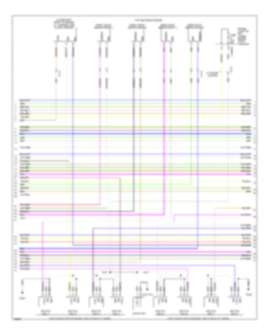
ENGINE PERFORMANCE
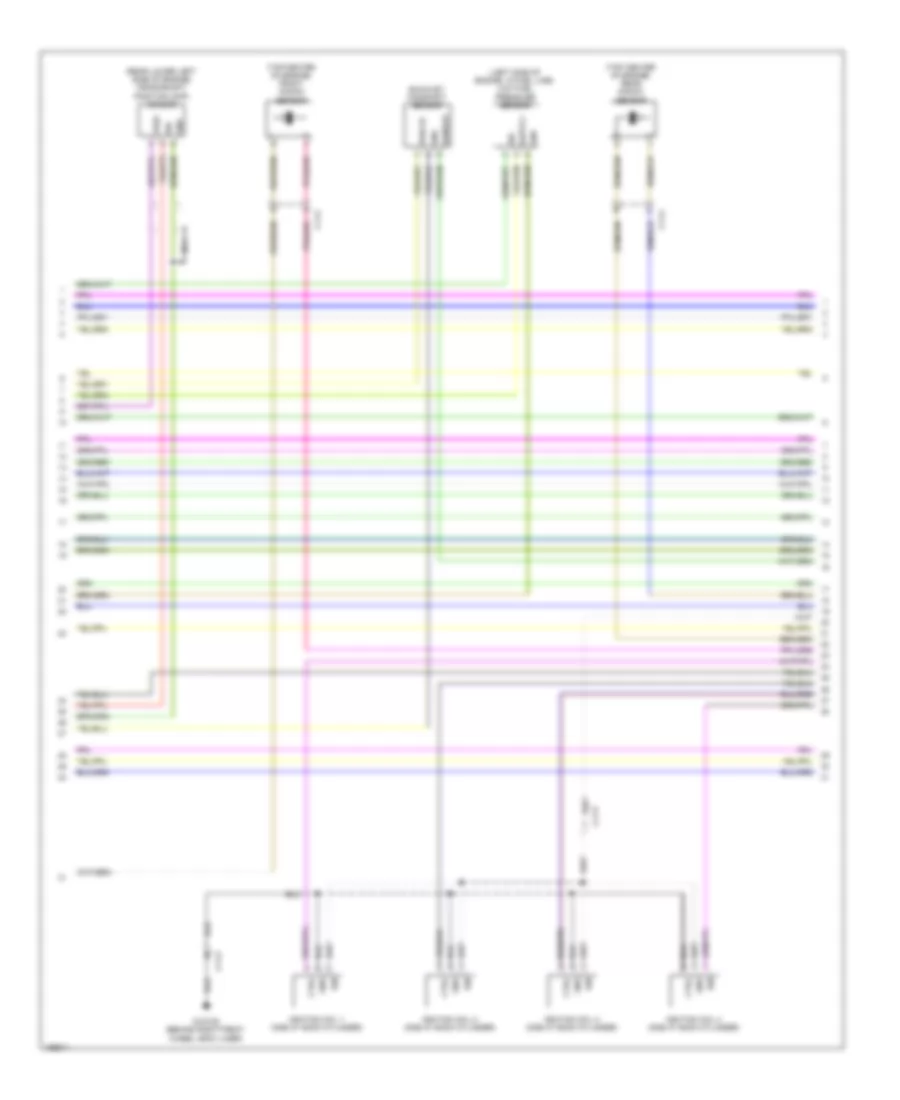
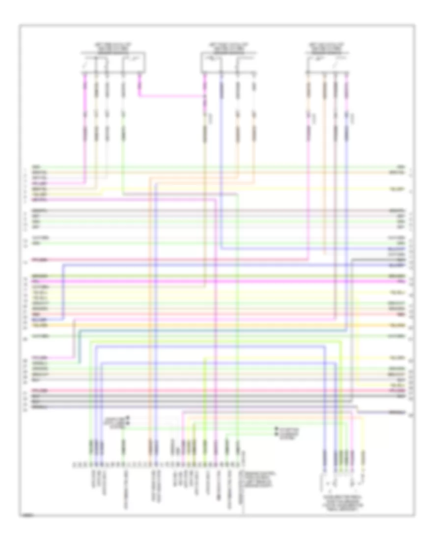
2.0L TURBO
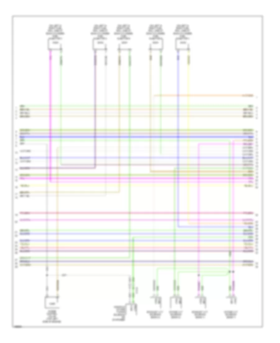
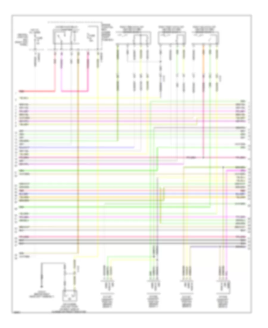
2.0L Turbo, Engine Performance Wiring Diagram (1 of 6) for Jaguar XF 3.0L AWD 2014

List of elements for 2.0L Turbo, Engine Performance Wiring Diagram (1 of 6) for Jaguar XF 3.0L AWD 2014:
- (on fuel rail, one at each cylinder)
- 5vflps
- Active engine mounting solenoid
- C11-c
- C11-p
- C1e105a
- Ccp can h
- Ccp can l
- Computer data lines system
- Emc
- Engine control module (ecm) (left rear of engine compt)
- Engine coolant temperature (ect) sensor
- Flps
- Fscvh
- Fscvl
- Fuel injector 1
- Fuel injector 2
- Fuel injector 3
- Fuel injector 4
- Fuel metering valve
- Gref g g case
- Gref g g casi
- Gref g g crs
- Gref g g iats
- Gref g g olts
- Gref g r acts
- Gref g r bps
- Gref g r cts
- Gref g r flps
- Gref g r imps
- Gref g r railps
- Gref g r tvp
- Hpinjv2 h
- Hpinjv2 l
- Hpinjv3 l
- Hpinjv4 h
- Hpinjv4 l
- Ip ams
- Ip bps
- Ip bts
- Ip crs
- Ip cts
- Ip iats
- Ip ks1b
- Ip ops
- Ip railps
- Ip rwts
- Mechanical fuel pump
- Oil pressure switch (lower right front of engine)
- Op hpinjv1 l
- Radiator outlet temperature sensor (in cooling radiator outlet hose)
- Tvp2
- Vref 5v bps
- Vref 5vcase
- Vref 5vcasi
- Vref 5vcrs
- Vref 5vimps
- Vref 5vrailps
- Vref 5vtvp
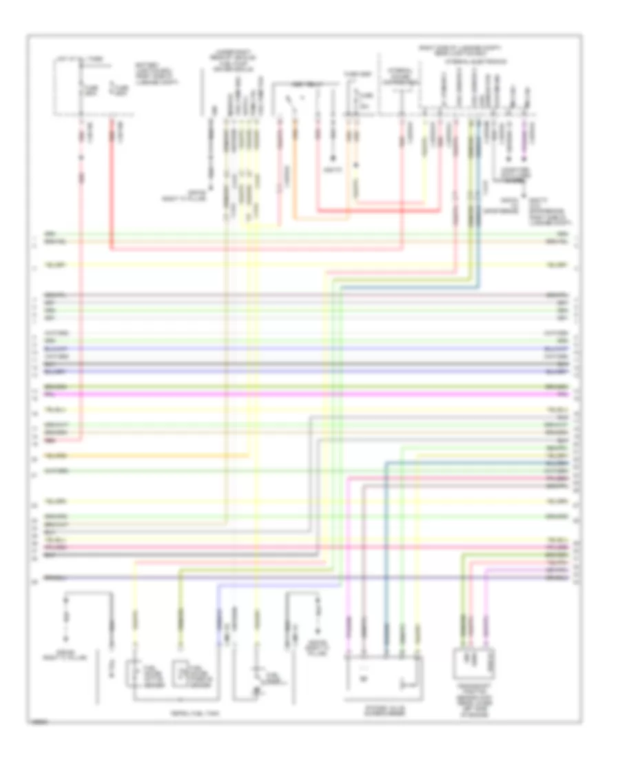
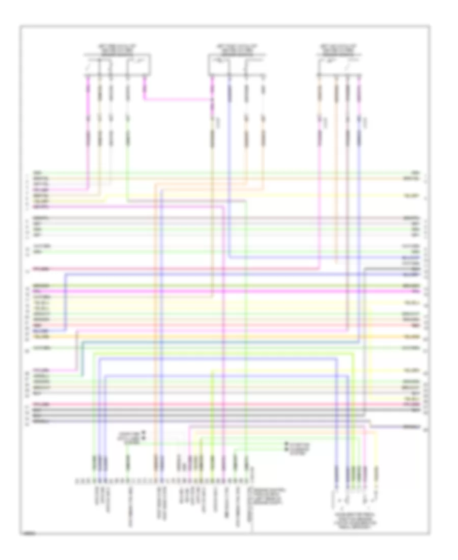
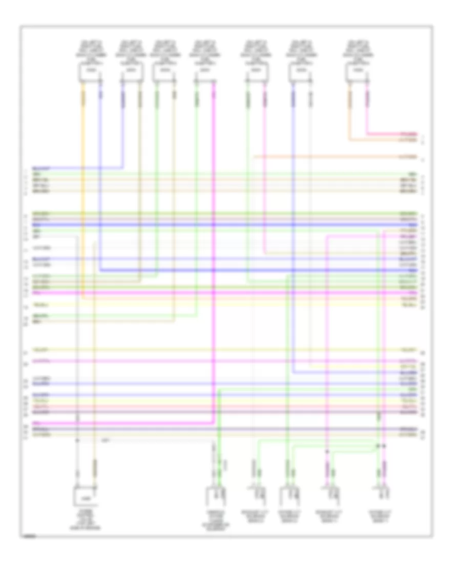
2.0L Turbo, Engine Performance Wiring Diagram (2 of 6) for Jaguar XF 3.0L AWD 2014
List of elements for 2.0L Turbo, Engine Performance Wiring Diagram (2 of 6) for Jaguar XF 3.0L AWD 2014:
- (left side of engine, in fuel line) low fuel pressure sensor
- (rear lower left side of engine) crankshaft position (ckp) sensor
- (top center of engine) front knock sensor
- (top center of engine) rear knock sensor
- C11-c
- C11-p
- Ctrl
- Exhaust camshaft sensor
- G1d108 (behind right front wheel arch liner)
- Gnd
- Ign
- Ignition coil 1 (one at each cylinder)
- Ignition coil 2 (one at each cylinder)
- Ignition coil 3 (one at each cylinder)
- Ignition coil 4 (one at each cylinder)
- Nca
- Pwr 5v
- Sensor
- Sig
- Vref
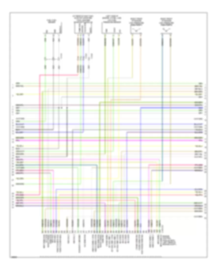
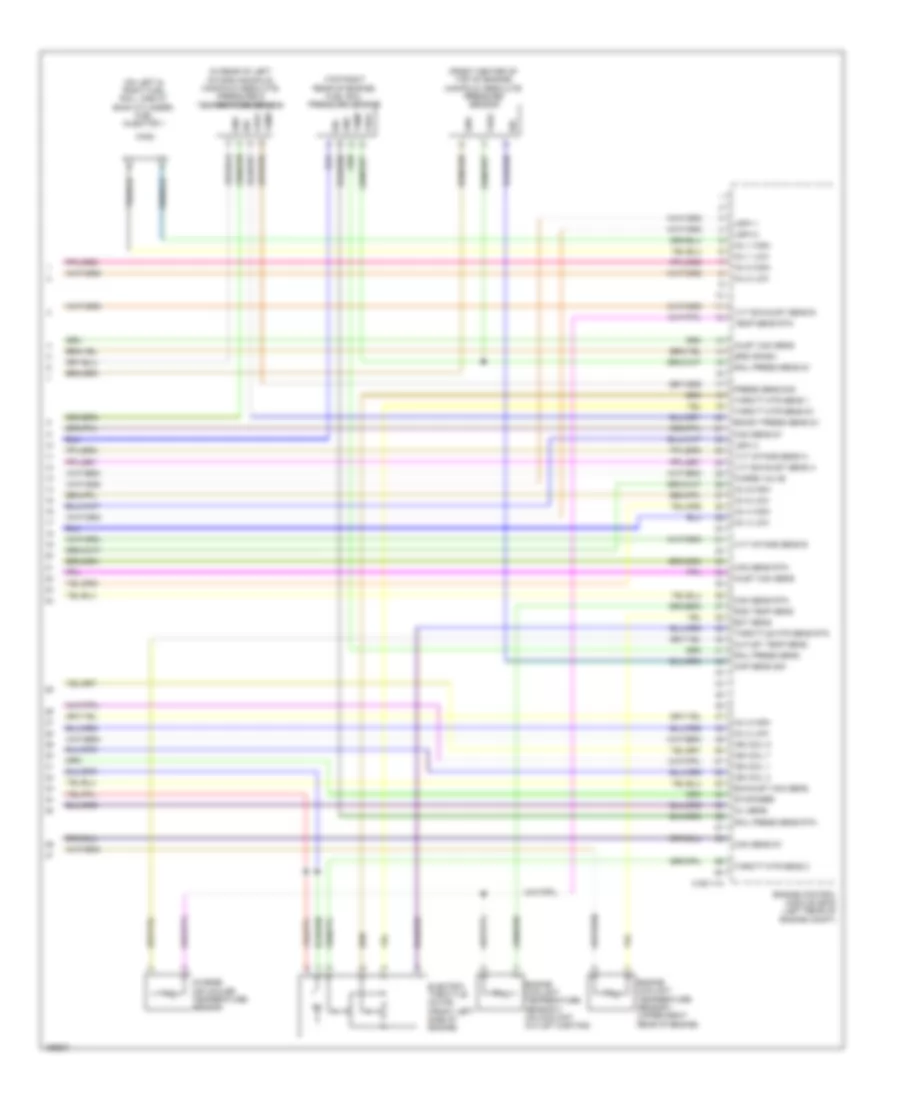
2.0L Turbo, Engine Performance Wiring Diagram (3 of 6) for Jaguar XF 3.0L AWD 2014
List of elements for 2.0L Turbo, Engine Performance Wiring Diagram (3 of 6) for Jaguar XF 3.0L AWD 2014:
- (front center of top of engine) manifold absolute pressure (map) sensor
- (lower right front of engine) engine oil temperature level sensor
- (top right rear of engine) fuel rail pressure sensor
- 5v pwr
- C1e105a
- Electric throttle motor (front center of engine)
- Engine control module (ecm) (left rear of engine compt)
- Gnd
- Hpinjv1 h
- Hpinjv3 h
- Intake camshaft sensor
- Ip case
- Ip casi
- Ip imps
- Ip ks1a
- Ip ks2a
- Ip ks2b
- Ip res01
- Lsuca
- Lsucp
- Lsuv
- Lsuvg
- Nernst v
- Op ios 1
- Op ios 2
- Op ios 3
- Op ios 4
- Pmp current
- Pre catalyst oxygen sensor
- Pwm cpv
- Pwm cvvte
- Pwm cvvti
- Pwm lsuh1
- Pwm wgv
- Sensor
- Sig
- Trim
- Tvmpos
- Tvp1
- Virtual gnd
- Vref
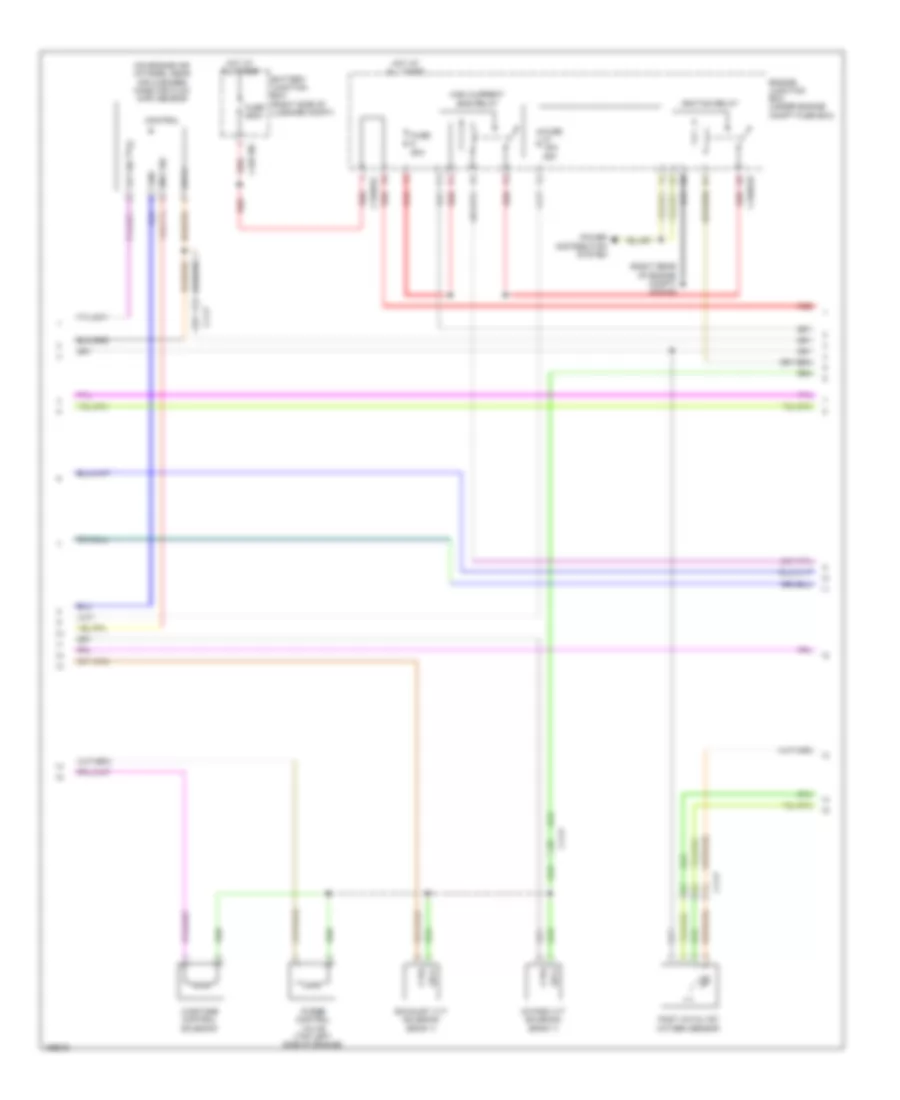
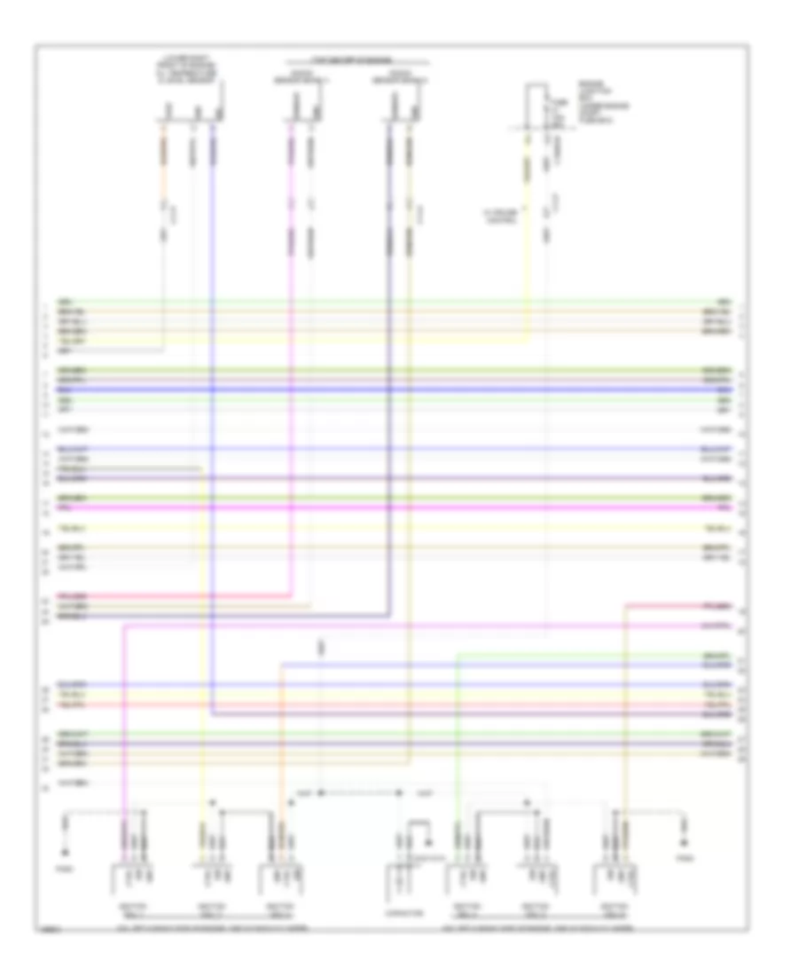
2.0L Turbo, Engine Performance Wiring Diagram (4 of 6) for Jaguar XF 3.0L AWD 2014
List of elements for 2.0L Turbo, Engine Performance Wiring Diagram (4 of 6) for Jaguar XF 3.0L AWD 2014:
- (on engine air intakes, near air cleaner) mass air flow (maf) sensor
- (right rear of engine compt) g1d123
- Battery junction box (right side of luggage compt)
- C11-p
- C1bb01b
- C1bb01c
- C4bf10c
- Control
- Ctrl
- Engine junction box (under engine compt fuse box)
- Exhaust vvt solenoid (bank 1)
- Fuse 15a/ 25a
- Fuse 250a
- Fuse 50a
- Gnd
- High current ems relay
- Hot at all times
- Iat sig
- Ignition relay
- Intake vvt solenoid (bank 1)
- Maf sig
- Post catalyst oxygen sensor
- Power distribution system
- Purge control valve (top left side of engine)
- Red
- Sply
- Wastage control solenoid
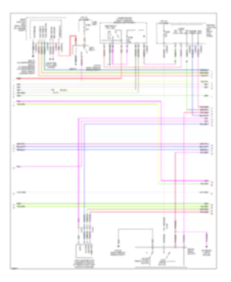
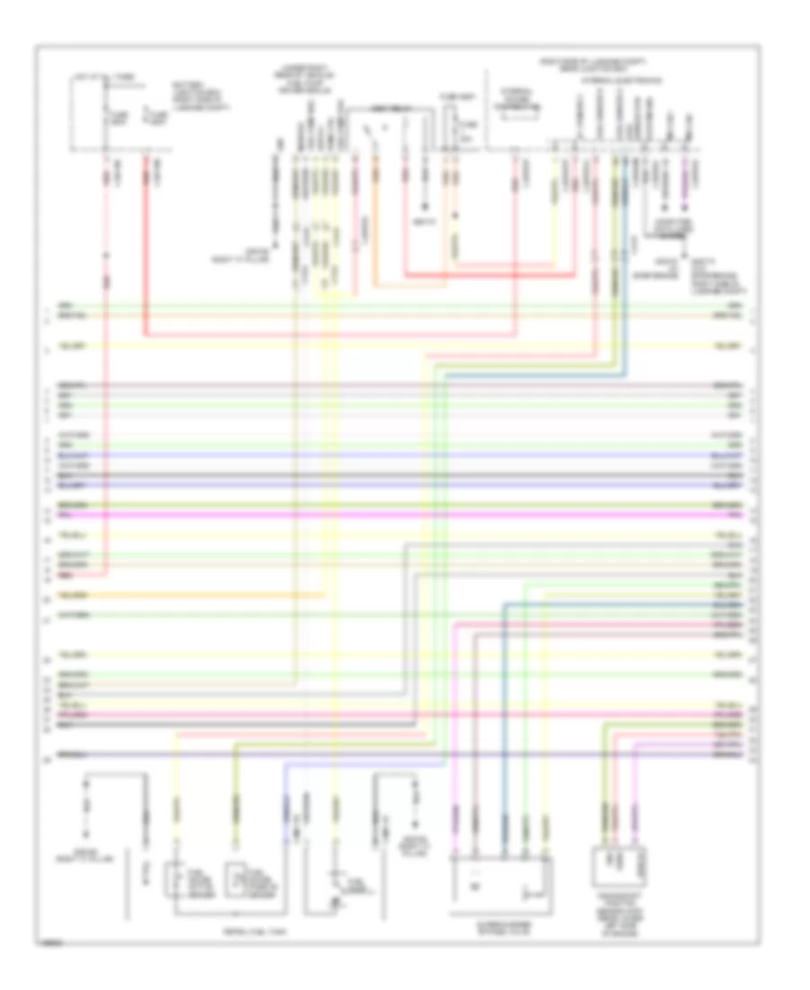
2.0L Turbo, Engine Performance Wiring Diagram (5 of 6) for Jaguar XF 3.0L AWD 2014
List of elements for 2.0L Turbo, Engine Performance Wiring Diagram (5 of 6) for Jaguar XF 3.0L AWD 2014:
- (under engine compt fuse box) engine junction box
- Assy relay
- Batt
- Brake pedal switch
- C11-p
- C13-a
- C13-d
- C1bb01b
- C3bp01e
- C3bp01f
- C3bp01g
- C3bp01j
- C4bp01cc
- C4bp01k
- C4bp01m
- Central junction box (right kick panel)
- Computer data lines system
- Cruise deactivation switch
- Ems ewu
- Engine crank
- Exterior lights system
- Foot brake switch
- Fuel sens a
- Fuel sens b
- Fuel sens rtn
- Fuse 20a
- Fuse 30a
- Fuse 5a
- Fuse assy
- G1d120 (right rear of engine compt)
- G1d123 (right rear of engine compt)
- G4d170
- G4d173 (w/o sportbrake) g4d151 (w/ sportbrake) (w/o sportbrake: right side of luggage compt)
- Heater
- Hego relay (full iso)
- Hot at all times
- Ign ctrl
- Ign sply
- Ms can pos
- Pump rtn
- Rear junction box (right side of luggage compt)
- Red
- System gnd
- Tank leakage pump diagnostic module (at rear of gas tank, on evap canister)
- Uhego rly ctrl
- Vlv rtn
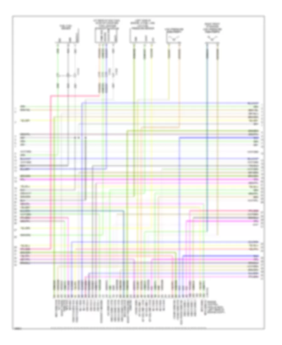
2.0L Turbo, Engine Performance Wiring Diagram (6 of 6) for Jaguar XF 3.0L AWD 2014
List of elements for 2.0L Turbo, Engine Performance Wiring Diagram (6 of 6) for Jaguar XF 3.0L AWD 2014:
- (behind right front wheel arch liner) g1d108
- (under engine compartment fuse box) engine junction box
- Accelerator pedal position (app) sensor (top of accelerator pedal bracket)
- Active sender
- Air conditioning system
- Ambient air temp
- Ambient air temp rtn
- App1 5v sply
- App1 rtn
- App1 sig
- App2 5v sply
- App2 rtn
- App2 sig
- Boost pressure & temperature sensor (on turbocharger)
- Brake sw diag
- Brake switch
- C11-p
- C13-a
- C1bb01b
- C1e105b
- C44-e
- C4bp01c
- C4mc11c
- C4mc11d
- Computer data lines system
- Cooling fans system
- Crank request
- Dmtl heater
- Dmtl pmp
- Dmtl valve
- Ecfc
- Ems rly ctrl
- Engine control module (ecm) (left rear of engine compt)
- Fuel gauge passive sensor
- Fuel pmp mod ctrl
- Fuel pmp monitor
- Fuel pump
- Fuel pump driver module (under right rear of vehicle)
- Fuel pump pos
- Fuse 10a/20a/ 30a
- Fuse 5a/10a
- Fuse 5a/10a/ 15a
- G r lsf1
- G3d162 (right "c" pillar)
- Gnd
- Gnd 1
- Gnd 2
- Gnd 3
- Hs can pos
- Ign sense
- Lsf1
- Lsfh1
- Monitor
- Petrol fuel tank
- Pwm ctrl
- Sply
- Srs crash
- Starting/ charging system
- Starting/ charging system transmissions system
- Stren
- Strph
- Strpl
- Strth
- Strtl
- T50r
- Wake up
3.0L SC
3.0L SC, Engine Performance Wiring Diagram (1 of 9) for Jaguar XF 3.0L AWD 2014
List of elements for 3.0L SC, Engine Performance Wiring Diagram (1 of 9) for Jaguar XF 3.0L AWD 2014:
- Ambient air temp
- Ambient air temp rtn
- B ign op
- Brake pedal switch
- Brk sw 1
- Brk sw 2
- Brk vacuum sw
- C11-p
- C11-r
- C13-c
- C13-d
- C13-e
- C1bb01b
- C1bb01c
- C1e111b
- C33-c
- Charge air coolant pump (on right side of charge air (front) radiator)
- Coolant pump ctrl
- Cooling fans system
- Crank request
- Dmtl heater
- Dmtl pump
- Dmtl valve
- Ecfc
- Engine control module (ecm) (left rear of engine compt)
- Engine junction box (under engine compt fuse box)
- Exterior lights system
- Flex fuel sens
- Fuel pmp mod ctrl
- Fuel pmp mod moni
- Fuse 10a/ 20a/ 30a
- Fuse 15a
- Fuse 40a
- Fuse 50a
- Fuse 5a/ 10a
- Fuse 5a/ 10a/ 15a
- G1d108 (behind right front wheel arch liner)
- G1d120 (right rear of engine compt)
- G1d131 (behind right headlight assembly)
- Gnd 1
- Gnd 2
- Gnd 3
- Hego a mid htr ctrl
- Hego a mid rtn
- Hego a mid sig
- Hego b mid rtn
- Hego b mid sig
- High current ems relay
- Hot at all times
- Iat1
- Iat2
- Ign
- Ign sens
- Lfps rtn
- Lfps sig
- Maf1 gnd
- Maf1 sig
- Maf2 gnd
- Maf2 sig
- Neutral
- P n sig
- Post hego a rtn
- Post hego a sig
- Red
- S/ charged water pump relay (half iso)
- Starting/ charging system
- Starting/charging system
- Str mtr ctrl pos
- T50
- Transmission shift module (under center console)
- Uhego a htr ctrl
- Uhego a nearnst vol
- Uhego a pmp current
- Uhego a virt gnd
- Uhego b nernst vol
- Uhego b pmp current
- Uhego b virt gnd
- Wake up
3.0L SC, Engine Performance Wiring Diagram (2 of 9) for Jaguar XF 3.0L AWD 2014
List of elements for 3.0L SC, Engine Performance Wiring Diagram (2 of 9) for Jaguar XF 3.0L AWD 2014:
- (right kick panel) central junction box
- Ambient air temperature sensor
- Brake vacuum switch (w/ twin start solenoid)
- C11-p
- C13-c
- C13-e
- C1bb01b
- C3a-a
- C3bp01c
- C3bp01e
- C3bp01f
- C3bp01g
- C3bp01j
- C3bp01k
- C3bp01m
- C3r114b
- C4bp01m
- Computer data lines system
- Defogger system
- Ems ewu
- Engine crank
- Engine junction box (under engine compt fuse box)
- Fpdb ign ctrl
- Fuse 20a
- Fuse 5a
- G1d120 (right rear of engine compt)
- G1d123 (right rear of engine compt)
- G3d138 (right kick panel)
- Gnd
- Hego relay (full iso)
- Hot at all times
- Iat
- Ign sply 2 fwd
- Ignition relay (half iso)
- Internal electronics
- Left door mirror assembly
- Mass air flow
- Ms can +
- Ms can -
- Park neutral sig
- Pos hs can
- Rear junction box (right side of luggage compt)
- Red
- Restraints control module (rcm) (under rear of center console)
- Sensor 1 (on engine air intakes, near air cleaner)
- Sensor 2 (on engine air intakes, near air cleaner)
- Sig
- Srs ens
- System gnd
- Uhego rly ctrl
- W/o deployable switch
3.0L SC, Engine Performance Wiring Diagram (3 of 9) for Jaguar XF 3.0L AWD 2014
List of elements for 3.0L SC, Engine Performance Wiring Diagram (3 of 9) for Jaguar XF 3.0L AWD 2014:
- C11-p
- Gnd
- Intake camshaft position sensor (bank 1)
- Intake camshaft position sensor (bank 2)
- Outlet camshaft position sensor (bank 1)
- Outlet camshaft position sensor (bank 2)
- Pwr 5v
- Red
- Right mid catalyst heated oxygen sensor (bank 1)
- Right post catalyst heated oxygen sensor (bank 1)
- Right pre catalyst heated oxygen sensor (bank 1)
- Sens
3.0L SC, Engine Performance Wiring Diagram (4 of 9) for Jaguar XF 3.0L AWD 2014
List of elements for 3.0L SC, Engine Performance Wiring Diagram (4 of 9) for Jaguar XF 3.0L AWD 2014:
- Accelerator pedal position sensor (top of accelerator pedal bracket)
- App1 5v sply
- App1 rtn
- App1 sig
- App2 5v sply
- App2 rtn
- App2 sig
- C11-p
- C1e111b
- Computer data lines system
- Ems relay ctrl
- Engine control module (ecm) (left rear of engine compt)
- Hs can +
- Hs can -
- Left mid catalyst heated oxygen sensor (bank 2)
- Left post catalyst heated oxygen sensor (bank 2)
- Left pre catalyst heated oxygen sensor (bank 2)
- Lfps 5v sply
- Post hego b rtn
- Post hego b sig
- Red
- Starting/ charging system
- Str pinion ctrl pos
- Uhego b htr ctrl
3.0L SC, Engine Performance Wiring Diagram (5 of 9) for Jaguar XF 3.0L AWD 2014
List of elements for 3.0L SC, Engine Performance Wiring Diagram (5 of 9) for Jaguar XF 3.0L AWD 2014:
- (right side of luggage compt) rear junction box
- (under right rear of vehicle) fuel pump driver module
- Assy relay
- B+ fpdm sply
- Battery junction box (right side of luggage compt)
- Bypass valve supercharger
- C13-a
- C44-e
- C4bf10b
- C4bf10c
- C4bp01c
- C4bp01cc
- C4bp01k
- C4bp01m
- C4bp01p
- C4bp01pp
- C4mc11c
- C4mc11d
- Computer data lines system
- Crankshaft position sensor (ckp) (rear lower left side of engine)
- Fuel gauge active sender
- Fuel gauge passive sender
- Fuel pump
- Fuel pump pos
- Fuel sender a
- Fuel sender b
- Fuse 250a
- Fuse 30a
- Fuse assy
- G3d162 (right "c" pillar)
- G4d151 (w/ sportbrake)
- G4d170
- G4d173 (w/o sportbrake) (right side of luggage compt)
- Gnd
- Hot at all times
- Internal electronics
- Internal power distribution
- Monitor
- Ms can +
- Ms can -
- Petrol fuel tank
- Pwm ctrl
- Pwr 5v
- Red
- Sender rtn fuel
- Sens
- System gnd
3.0L SC, Engine Performance Wiring Diagram (6 of 9) for Jaguar XF 3.0L AWD 2014
List of elements for 3.0L SC, Engine Performance Wiring Diagram (6 of 9) for Jaguar XF 3.0L AWD 2014:
- (at rear of gas tank, on evap canister) tank leakage diagnostic module
- (left side of engine, in fuel line) low fuel pressure sensor
- (right front of engine) high pressure fuel pump 1
- (right front of engine) high pressure fuel pump 2
- +5v
- Batt
- Boost press
- C11-u
- C13-a
- C13-d
- C1e111a
- Crank sens
- Crank sens rtn
- Crank sens sig
- Ect rtn
- Engine control module (ecm) (left rear of engine compt)
- Exhaust cam sens
- Fuel flex sensor
- Gnd
- Heater
- Hp fuel pmp 1
- Hp fuel pmp 1 rtn
- Hp fuel pmp 2
- Hp fuel pmp 2 rtn
- Ign coil 2
- Ign coil 5
- Inj 2 high
- Inj 2 low
- Inj 6 high
- Inj 6 low
- Knock sens 1
- Knock sens 1 rtn
- Knock sens 2
- Knock sens 2 rtn
- Map sens rtn
- Mtr sens
- Mtr sens 5v
- Mtr sens rtn
- Oil sens rtn
- Pump rtn
- Rail press sens sig
- Sens rtn mtr pos
- Sens sig boost press
- Sig
- Throttle mtr pos
- Valve rtn
- Vout
3.0L SC, Engine Performance Wiring Diagram (7 of 9) for Jaguar XF 3.0L AWD 2014
List of elements for 3.0L SC, Engine Performance Wiring Diagram (7 of 9) for Jaguar XF 3.0L AWD 2014:
- (lower right front of engine) oil temperature & level sensor
- (on left & right side of engine, one at each cylinder)
- (top center of engine)
- C11-a
- C11-p
- C1bb01b
- Capacitor
- Ctrl
- Engine junction box (under engine compt fuse box)
- Fuse 15a/ 25a
- G1d1101a
- Gnd
- Ign
- Ignition coil 1
- Ignition coil 2
- Ignition coil 3
- Ignition coil 4
- Ignition coil 5
- Ignition coil 6
- Knock sensor (bank 1)
- Knock sensor (bank 2)
- Pi080
- Pi082
- Sensor
- Sig
- Vref
- W/ cruise control
3.0L SC, Engine Performance Wiring Diagram (8 of 9) for Jaguar XF 3.0L AWD 2014
List of elements for 3.0L SC, Engine Performance Wiring Diagram (8 of 9) for Jaguar XF 3.0L AWD 2014:
- (on left & right fuel rail, one at each cylinder) fuel injector 2
- (on left & right fuel rail, one at each cylinder) fuel injector 3
- (on left & right fuel rail, one at each cylinder) fuel injector 4
- (on left & right fuel rail, one at each cylinder) fuel injector 5
- (on left & right fuel rail, one at each cylinder) fuel injector 6
- C11-a
- Ctrl
- Exhaust vvt solenoid (bank 1)
- Exhaust vvt solenoid (bank 2)
- Intake vvt solenoid (bank 1)
- Intake vvt solenoid (bank 2)
- Manifold intake tuning solenoid or symposer
- Purge control valve (top left side of engine)
- Sply
3.0L SC, Engine Performance Wiring Diagram (9 of 9) for Jaguar XF 3.0L AWD 2014
List of elements for 3.0L SC, Engine Performance Wiring Diagram (9 of 9) for Jaguar XF 3.0L AWD 2014:
- (front center of top of engine) manifold absolute pressure sensor
- (in rear of left intake manifold) manifold absolute pressure & temperature sensor
- (on left & right fuel rail, one at each cylinder) fuel injector 1
- (top right rear of engine) fuel rail pressure sensor
- Boost press sens
- C1e111a
- Cam sens 5v
- Cam sens rtn
- Cam sensors rtn
- Charge air cooler temperature sensor
- Ect sens
- Electric throttle motor (top left of engine)
- Engine control module (ecm) (left rear of engine compt)
- Engine coolant temperature sensor 1 (upper right rear of engine)
- Engine coolant temperature sensor 2 (on coolant outlet casting)
- Exhaust cam sens
- Gnd
- Ign coil 1
- Ign coil 3
- Ign coil 4
- Ign coil 6
- Inj 1 high
- Inj 1 low
- Inj 3 high
- Inj 3 low
- Inj 4 high
- Inj 4 low
- Inj 5 high
- Inj 5 low
- Inlet cam sens
- Lsfh 1
- Lsfh 2
- Lsfh 4
- Map sens sig
- Oil sens
- Outlet temp sens
- Press sens sig
- Purge valve
- Rad temp sens
- Rail press sens
- Rail press sens rtn
- Sig
- Srs crash
- Symposer
- Temp
- Temp sens rtn
- Thrott mtr sens 1
- Thrott mtr sens 2
- Thrott mtr sens 5v
- Throttle mtr sens rtn
- Vref
- Vvt exhaust sens a
- Vvt exhaust sens b
- Vvt intake sens a
- Vvt intake sens b
5.0L SC
5.0L SC, Engine Performance Wiring Diagram (1 of 9) for Jaguar XF 3.0L AWD 2014
List of elements for 5.0L SC, Engine Performance Wiring Diagram (1 of 9) for Jaguar XF 3.0L AWD 2014:
- Ambient air temp
- Ambient air temp rtn
- B ign op
- Brake pedal switch
- Brk sw 1
- Brk sw 2
- Brk vacuum sw
- C11-p
- C13-c
- C13-d
- C13-e
- C1bb01b
- C1bb01c
- C1e111b
- C33-c
- Cooling fans system
- Crank request
- Dmtl heater
- Dmtl pump
- Dmtl valve
- Ecfc
- Engine control module (ecm) (left rear of engine compt)
- Engine junction box (under engine compt fuse box)
- Exterior lights system
- Flex fuel sens
- Fuel pmp mod ctrl
- Fuel pmp mod moni
- Fuse 10a/ 20a/ 30a
- Fuse 40a
- Fuse 50a
- Fuse 5a/ 10a
- Fuse 5a/ 10a/ 15a
- G1d108 (behind right front wheel arch liner)
- G1d120 (right rear of engine compt)
- Gnd 1
- Gnd 2
- Gnd 3
- Hego a mid htr ctrl
- Hego a mid rtn
- Hego a mid sig
- Hego b mid rtn
- Hego b mid sig
- High current ems relay
- Hot at all times
- Iat1
- Iat2
- Ic coolant pmp ctrl
- Ign
- Ign sens
- Lfps rtn
- Lfps sig
- Maf1 gnd
- Maf1 sig
- Maf2 gnd
- Maf2 sig
- Neutral
- P n sig
- Post hego a rtn
- Post hego a sig
- Red
- Starting/ charging system
- Starting/charging system
- Str mtr ctrl pos
- T50
- Transmission control module (on transmission)
- Transmission shift module (under center console)
- Uhego a htr ctrl
- Uhego a nearnst vol
- Uhego a pmp current
- Uhego a virt gnd
- Uhego b nernst vol
- Uhego b pmp current
- Uhego b virt gnd
- Wake up
5.0L SC, Engine Performance Wiring Diagram (2 of 9) for Jaguar XF 3.0L AWD 2014
List of elements for 5.0L SC, Engine Performance Wiring Diagram (2 of 9) for Jaguar XF 3.0L AWD 2014:
- (in mirror) left door mirror assembly
- (right kick panel) central junction box
- Ambient air temperature sensor
- Brake vacuum switch (w/ twin start solenoid)
- C11-p
- C13-c
- C13-e
- C1bb01b
- C3a-a
- C3bp01c
- C3bp01e
- C3bp01g
- C3bp01j
- C3bp01k
- C3bp01m
- C3r114b
- C4bp01m
- Computer data lines system
- Defogger system
- Ems ewu
- Engine crank
- Engine junction box (under engine compt fuse box)
- Fpdb ign ctrl
- Fuse 20a
- G1d120 (right rear of engine compt)
- G1d123 (right rear of engine compt)
- G3d138 (right kick panel)
- Gnd
- Hego relay (full iso)
- Iat
- Ign sply 2 fwd
- Ignition relay (half iso)
- Internal electronics
- Mass air flow
- Ms can +
- Ms can -
- Park neutral sig
- Pos hs can
- Rear junction box (right side of luggage compt)
- Red
- Restraints control module (rcm) (under rear of center console)
- Sensor 1
- Sensor 2 (on engine air intakes, near air cleaner)
- Sig
- Srs ens
- System gnd
- Uhego rly ctrl
- W/o deployable switch
5.0L SC, Engine Performance Wiring Diagram (3 of 9) for Jaguar XF 3.0L AWD 2014
List of elements for 5.0L SC, Engine Performance Wiring Diagram (3 of 9) for Jaguar XF 3.0L AWD 2014:
- Air charge coolant pump (on right side of charge air (front) radiator)
- C11-p
- C11-r
- C1bb01b
- C3bp01f
- Central junction box (right kick panel)
- Engine junction box (under engine compt fuse box)
- Fuse
- Fuse 15a
- G1d131 (behind right headlight assembly)
- Gnd
- Hot at all times
- Intake camshaft position sensor (bank 1)
- Intake camshaft position sensor (bank 2)
- Outlet camshaft position sensor (bank 1)
- Outlet camshaft position sensor (bank 2)
- Pwr 5v
- Red
- Right mid catalyst heated oxygen sensor (bank 1)
- Right post catalyst heated oxygen sensor (bank 1)
- Right pre catalyst heated oxygen sensor (bank 1)
- Sens
- Water pump relay (half iso)
5.0L SC, Engine Performance Wiring Diagram (4 of 9) for Jaguar XF 3.0L AWD 2014
List of elements for 5.0L SC, Engine Performance Wiring Diagram (4 of 9) for Jaguar XF 3.0L AWD 2014:
- Accelerator pedal position sensor (top of accelerator pedal bracket)
- App1 5v sply
- App1 rtn
- App1 sig
- App2 5v sply
- App2 rtn
- App2 sig
- C11-p
- C1e111b
- Computer data lines system
- Ems relay ctrl
- Engine control module (ecm) (left rear of engine compt)
- Hs can +
- Hs can -
- Left mid catalyst heated oxygen sensor (bank 2)
- Left post catalyst heated oxygen sensor (bank 2)
- Left pre catalyst heated oxygen sensor (bank 2)
- Lfps 5v sply
- Post hego b rtn
- Post hego b sig
- Red
- Starting/ charging system
- Str pinion ctrl pos
- Uhego b htr ctrl
5.0L SC, Engine Performance Wiring Diagram (5 of 9) for Jaguar XF 3.0L AWD 2014
List of elements for 5.0L SC, Engine Performance Wiring Diagram (5 of 9) for Jaguar XF 3.0L AWD 2014:
- (right side of luggage compt) rear junction box
- (under right rear of vehicle) fuel pump driver module
- Assy relay
- B+ fpdm sply
- Battery junction box (right side of luggage compt)
- C13-a
- C44-e
- C4bf10b
- C4bf10c
- C4bp01c
- C4bp01cc
- C4bp01k
- C4bp01m
- C4bp01p
- C4bp01pp
- C4mc11c
- C4mc11d
- Computer data lines system
- Crankshaft position sensor (ckp) (rear lower left side of engine)
- Fuel gauge active sender
- Fuel gauge passive sender
- Fuel pump
- Fuel pump pos
- Fuel sender a
- Fuel sender b
- Fuse 250a
- Fuse 30a
- Fuse assy
- G3d162 (right "c" pillar)
- G4d151 (w/ sportbrake)
- G4d170
- G4d173 (w/o sportbrake) (right side of luggage compt)
- Gnd
- Hot at all times
- Internal electronics
- Internal power distribution
- Monitor
- Ms can +
- Ms can -
- Petrol fuel tank
- Pwm ctrl
- Pwr 5v
- Red
- Sender rtn fuel
- Sens
- Supercharger bypass valve
- System gnd
5.0L SC, Engine Performance Wiring Diagram (6 of 9) for Jaguar XF 3.0L AWD 2014
List of elements for 5.0L SC, Engine Performance Wiring Diagram (6 of 9) for Jaguar XF 3.0L AWD 2014:
- (at rear of gas tank, on evap canister) tank leakage diagnostic module
- (left side of engine, in fuel line) low fuel pressure sensor
- (right front of engine) high pressure fuel pump 2
- +5v
- Batt
- Boost press
- C11-u
- C13-a
- C13-d
- C1e111a
- Crank sens
- Crank sens rtn
- Crank sens sig
- Ect rtn
- Engine control module (ecm) (left rear of engine compt)
- Exhaust cam sens
- Fuel flex sensor
- Gnd
- Heater
- High pressure fuel pump 1
- Hp fuel pmp 1
- Hp fuel pmp 1 rtn
- Hp fuel pmp 2
- Hp fuel pmp 2 rtn
- Ign coil 2
- Ign coil 4
- Ign coil 6
- Ign coil 8
- Inj 3 high
- Inj 3 low
- Inj 5 high
- Inj 5 low
- Inj 7 high
- Inj 7 low
- Knock sens 1
- Knock sens 1 rtn
- Knock sens 2
- Knock sens 3
- Knock sens 3 rtn
- Knock sens 4
- Knock sens 4 rtn
- Map sens rtn
- Mtr sens
- Mtr sens 5v
- Mtr sens rtn knock sens 2 rtn
- Oil sens rtn
- Pump rtn
- Rail press sens sig
- Sens rtn mtr pos
- Sens sig boost press sens
- Sig
- Throttle mtr pos
- Valve rtn
- Vout
5.0L SC, Engine Performance Wiring Diagram (7 of 9) for Jaguar XF 3.0L AWD 2014
List of elements for 5.0L SC, Engine Performance Wiring Diagram (7 of 9) for Jaguar XF 3.0L AWD 2014:
- (left & right side of engine, one at each cylinder)
- (lower right front of engine) oil temperature & level sensor
- (top center of engine)
- C11-a
- C11-p
- C1bb01b
- Capacitor
- Ctrl
- Engine junction box (under engine compt fuse box)
- Front knock sensor (bank 1)
- Front knock sensor (bank 2)
- Fuse 15a/ 25a
- G1d1101a
- Gnd
- Ign
- Ignition coil 1
- Ignition coil 2
- Ignition coil 3
- Ignition coil 4
- Ignition coil 5
- Ignition coil 6
- Ignition coil 7
- Ignition coil 8
- Pi080
- Pi082
- Rear knock sensor (bank 1)
- Rear knock sensor (bank 2)
- Sensor
- Sig
- Vref
- W/ cruise control
5.0L SC, Engine Performance Wiring Diagram (8 of 9) for Jaguar XF 3.0L AWD 2014
List of elements for 5.0L SC, Engine Performance Wiring Diagram (8 of 9) for Jaguar XF 3.0L AWD 2014:
- (on left & right fuel rail, one at each cylinder) fuel injector 2
- (on left & right fuel rail, one at each cylinder) fuel injector 3
- (on left & right fuel rail, one at each cylinder) fuel injector 4
- (on left & right fuel rail, one at each cylinder) fuel injector 5
- (on left & right fuel rail, one at each cylinder) fuel injector 6
- (on left & right fuel rail, one at each cylinder) fuel injector 7
- (on left & right fuel rail, one at each cylinder) fuel injector 8
- C11-a
- Ctrl
- Exhaust vvt solenoid (bank 1)
- Exhaust vvt solenoid (bank 2)
- Intake vvt solenoid (bank 1)
- Intake vvt solenoid (bank 2)
- Manifold intake tuning symposer or solenoid
- Purge control valve (top left side of engine)
- Sply
5.0L SC, Engine Performance Wiring Diagram (9 of 9) for Jaguar XF 3.0L AWD 2014
List of elements for 5.0L SC, Engine Performance Wiring Diagram (9 of 9) for Jaguar XF 3.0L AWD 2014:
- (front center of top of engine) manifold absolute pressure sensor
- (in rear of left intake manifold) manifold absolute pressure & temperature sensor
- (on left & right fuel rail, one at each cylinder) fuel injector 1
- (top right rear of engine) fuel rail pressure sensor
- Boost press sens 5v
- C1e111a
- Cam sens 5v
- Cam sens rtn
- Charge air cooler temperature sensor
- Ect sens
- Electric throttle motor (front left side of engine)
- Engine control module (ecm) (left rear of engine compt)
- Engine coolant temperature sensor 1 (upper right rear of engine)
- Engine coolant temperature sensor 2 (on coolant outlet casting)
- Exhaust cam sens
- Gnd
- Ign coil 1
- Ign coil 3
- Ign coil 5
- Ign coil 7
- Inj 1 high
- Inj 1 low
- Inj 2 high
- Inj 2 low
- Inj 4 high
- Inj 4 low
- Inj 6 high
- Inj 6 low
- Inj 8 high
- Inj 8 low
- Inlet cam sens
- Lsfh 1
- Lsfh 2
- Lsfh 4
- Map sens sig
- Oil sens
- Outlet temp sens
- Press sens sig
- Purge valve
- Rad temp sens
- Rail press sens
- Rail press sens 5v
- Rail press sens rtn
- Sig
- Srs crash
- Symposer
- Temp
- Temp sens rtn
- Thrott mtr sens 1
- Thrott mtr sens 2
- Thrott mtr sens 5v
- Throttle mtr sens rtn
- Vref
- Vvt exhaust sens a
- Vvt exhaust sens b
- Vvt intake sens a
- Vvt intake sens b