ENGINE PERFORMANCE
4.0L
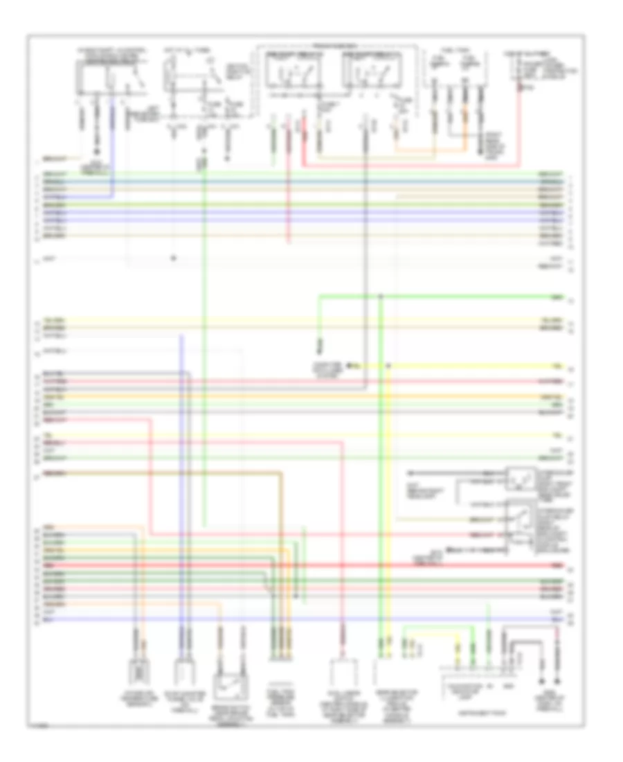
4.0L, Engine Performance Wiring Diagram (1 of 4) for Jaguar XJR 2000

List of elements for 4.0L, Engine Performance Wiring Diagram (1 of 4) for Jaguar XJR 2000:
- (center of dash, on firewall)
- (front of left front fender) g100
- (pin 13 not used)
- Acc
- Air conditioning system
- Cooling fans system
- Cruise control system
- Data link connector (dlc) (on transmission tunnel)
- Ecm & tcm cooling fan
- Em19
- Em20
- Em80
- Em81
- Em82
- Ems control relay
- Engine control module (right rear side of eng compt, in control module enclosure)
- Engine coolant temperature sensor (rear of eng, in top hose)
- Engine management fuse box
- Fuse 10a
- Fuse 30a
- Fuse 5a
- G121 (center of firewall)
- G206
- Hot at all times
- Ignition switch
- Inertia switch (behind right kick panel)
- Manifold absolute pressure sensor
- Mass airflow sensor (rear of air cleaner)
- Nca
- Off
- P133
- P142
- P16
- Parking brake switch (in center console assembly)
- Pedal position sensor
- Pnk
- Red
- Run
- Start
- Starting/ charging system
- Throttle assembly
- Throttle motor
- Throttle position sensor
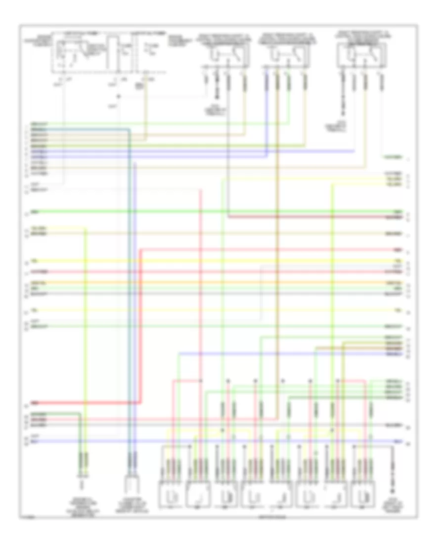
4.0L, Engine Performance Wiring Diagram (2 of 4) for Jaguar XJR 2000
List of elements for 4.0L, Engine Performance Wiring Diagram (2 of 4) for Jaguar XJR 2000:
- (in eng compt, in control module enclosure) ignition coil relay
- (right rear side of trunk) g405
- Brake switch (near brake pedal mounting assembly)
- Bt10
- Bt11
- Bt12
- Cc14
- Computer data lines system
- Dual linear switch (center console, at right side of gear selector assembly)
- Evap canister purge valve (on firewall)
- Fc24
- Fuel pump 1
- Fuel pump 1 relay (4)
- Fuel pump 2
- Fuel pump 2 relay (1)
- Fuel tank
- Fuel tank pressure sensor (in top of fuel tank)
- Fuse 10a
- Fuse 20a
- Fuse 7 20a
- G107 (behind right headlamp)
- G121 (center of firewall)
- G206 (center of dash, on firewall)
- G212 (center of fire wall)
- Gear selector illumination module (in center console assembly)
- Gnd
- High power protection module
- Hot at all times
- Ignition positive relay
- Instrument pack
- Intake air temperature sensor 2
- Intercooler pump (right front eng compt, near crush tube)
- Intercooler pump relay (right rear of eng compt, in control module enclosure)
- Left heelboard fuse box
- Malfunction indicator lamp
- Nca
- Power fuse 250a
- Red
- Red bt63
- Trunk fuse box
4.0L, Engine Performance Wiring Diagram (3 of 4) for Jaguar XJR 2000
List of elements for 4.0L, Engine Performance Wiring Diagram (3 of 4) for Jaguar XJR 2000:
- (right rear eng compt, in control module enclosure) fuel injection relay
- (right rear eng compt, in control module enclosure) oxygen sensor heaters relay
- (right rear eng compt, in control module enclosure) throttle motor power relay
- Canister closed valve (under right rear of vehicle)
- Engine compartment fuse box
- Engine management fuse box
- Engine oil temperature sensor (on block, below generator)
- Fuse 10a
- Fuse 15a
- G100 (front of left front fender)
- G121 (center of firewall)
- Hot at all times
- Ignition coils
- Ignition positive relay
- Lf6
- Lf7
- M20
- Red
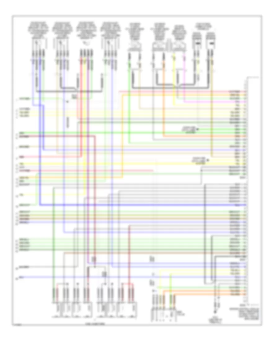
4.0L, Engine Performance Wiring Diagram (4 of 4) for Jaguar XJR 2000
List of elements for 4.0L, Engine Performance Wiring Diagram (4 of 4) for Jaguar XJR 2000:
- (on eng, rear of bed plate) crankshaft position sensor
- (on exhaust system, near bracket on top of transmission) downstream oxygen sensor "a"
- (on exhaust system, near bracket on top of transmission) downstream oxygen sensor "b"
- (on exhaust system, near bracket on top of transmission) upstream heated oxygen sensor "a"
- (on exhaust system, near bracket on top of transmission) upstream heated oxygen sensor "b"
- (on rear "a" bank cylinder head) camshaft position sensor "a" bank
- (on rear "b" bank cylinder head) camshaft position sensor "b" bank
- (top of eng, under intake manifold)
- Braided
- Computer data lines system
- Egr valve
- Em83
- Em84
- Em85
- Engine control module (right rear side of eng compt, in control module enclosure)
- Fuel injectors
- G121 (center of firewall)
- Knock sensor "a" bank
- Knock sensor "b" bank
- Nca
- Red