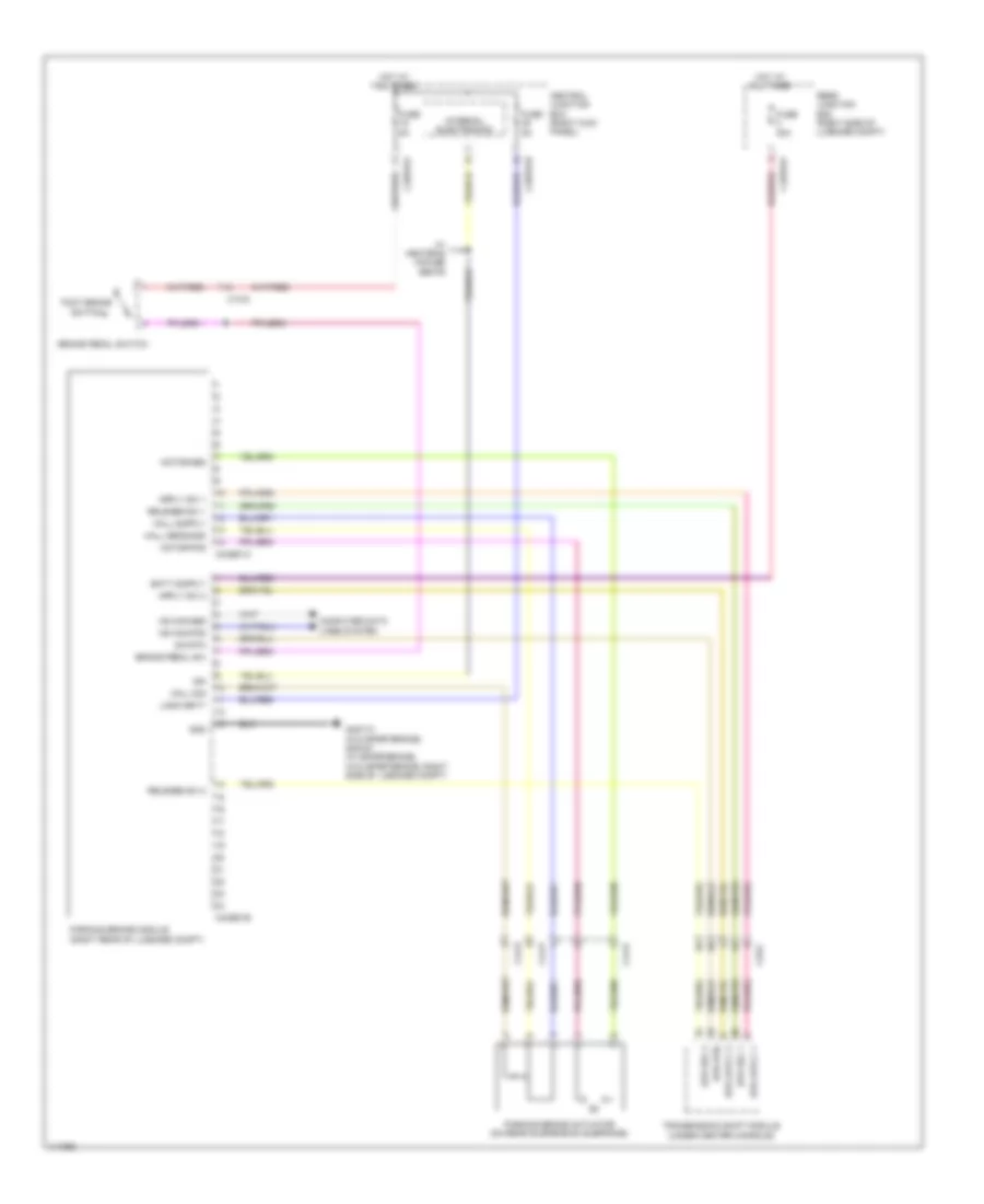
SHIFT INTERLOCK
Shift Interlock Wiring Diagram for Jaguar XFR 2013
List of elements for Shift Interlock Wiring Diagram for Jaguar XFR 2013:
- Brake pedal sw
- Brake pedal switch
- C13-d
- C33-c
- C3bp01d
- C3bp01f
- C44-p
- C44-r
- C4bp01f
- C4cb01a
- C4cb01b
- Central junction box (right kick panel)
- Computer data lines system
- Epb rel 1
- Epb rel 2
- Epb rtn
- Foot brake switch
- Fuse 30a
- Fuse 5a
- G4d173 (w/o sportbrake) g4d151 (w/ sportbrake) (w/o sportbrake: right side of luggage compt)
- Gnd
- Hall sens gnd
- Hall sig
- Hot at all times
- Hs can pos
- Ign
- Internal electronics
- Logic batt
- Motor pos
- Parking brake actuator (on rear suspension subframe)
- Parking brake module (right rear of luggage compt)
- Rear junction box (right side of luggage compt)
- Release sw 1
- Release sw 2
- Sw rtn
- Transmission shift module (under center console)
- W/ heated & cooled seats
 English