SHIFT INTERLOCK
Park Brake Release Wiring Diagram for Jaguar XJR 2005

List of elements for Park Brake Release Wiring Diagram for Jaguar XJR 2005:
- Computer data lines system
- Cr32
- Cr50
- Cr56
- Electronic parking brake switch
- Fuse 30a
- Fuse 5a
- G18 (under left side of left rear seat)
- G24 (at right front side of trunk)
- Hall effect sensor
- Hot at all times
- Hot in acc or run
- Parking brake control module (right rear of trunk)
- Parking brake motor (on rear suspension subframe)
- Passenger junction fuse box (behind right end of dash)
- Rear power distribution fuse box (at right rear of trunk)
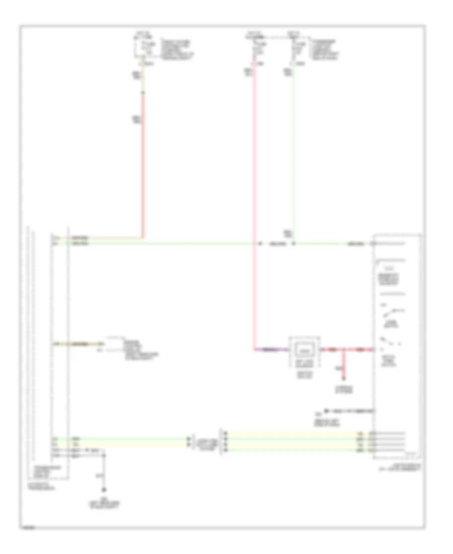
Shift Interlock Wiring Diagram for Jaguar XJR 2005
List of elements for Shift Interlock Wiring Diagram for Jaguar XJR 2005:
- (behind left side of dash)
- Automatic transmission
- Computer data lines system
- Cr49
- Cr6
- Ec40
- Engine control module (right rear side of eng compt)
- Front power distribution fuse box (right front of engine compt)
- Fuse f17 10a
- Fuse f33 5a
- Fuse f41 20a
- G30 (left rear side of eng compt)
- G32
- Gearshift interlock solenoid
- Hot at all times
- Hot in run
- Ignition switch
- J-gate module (at j gate assembly)
- Key lock solenoid
- Mode switch
- Not-in- park switch
- Passenger junction fuse box (behind right end of dash)
- Pi1
- Red
- Transmission control module
- Warning systems